WO2018074854A1 - 엑스선 영상 표시 장치 및 그 방법 - Google Patents
엑스선 영상 표시 장치 및 그 방법 Download PDFInfo
- Publication number
- WO2018074854A1 WO2018074854A1 PCT/KR2017/011560 KR2017011560W WO2018074854A1 WO 2018074854 A1 WO2018074854 A1 WO 2018074854A1 KR 2017011560 W KR2017011560 W KR 2017011560W WO 2018074854 A1 WO2018074854 A1 WO 2018074854A1
- Authority
- WO
- WIPO (PCT)
- Prior art keywords
- ray
- image
- frame data
- layer
- display unit
- Prior art date
- Legal status (The legal status is an assumption and is not a legal conclusion. Google has not performed a legal analysis and makes no representation as to the accuracy of the status listed.)
- Ceased
Links
Images


Classifications
-
- A—HUMAN NECESSITIES
- A61—MEDICAL OR VETERINARY SCIENCE; HYGIENE
- A61B—DIAGNOSIS; SURGERY; IDENTIFICATION
- A61B6/00—Apparatus or devices for radiation diagnosis; Apparatus or devices for radiation diagnosis combined with radiation therapy equipment
- A61B6/50—Apparatus or devices for radiation diagnosis; Apparatus or devices for radiation diagnosis combined with radiation therapy equipment specially adapted for specific body parts; specially adapted for specific clinical applications
- A61B6/51—Apparatus or devices for radiation diagnosis; Apparatus or devices for radiation diagnosis combined with radiation therapy equipment specially adapted for specific body parts; specially adapted for specific clinical applications for dentistry
-
- A—HUMAN NECESSITIES
- A61—MEDICAL OR VETERINARY SCIENCE; HYGIENE
- A61B—DIAGNOSIS; SURGERY; IDENTIFICATION
- A61B6/00—Apparatus or devices for radiation diagnosis; Apparatus or devices for radiation diagnosis combined with radiation therapy equipment
- A61B6/02—Arrangements for diagnosis sequentially in different planes; Stereoscopic radiation diagnosis
- A61B6/03—Computed tomography [CT]
- A61B6/032—Transmission computed tomography [CT]
-
- A—HUMAN NECESSITIES
- A61—MEDICAL OR VETERINARY SCIENCE; HYGIENE
- A61B—DIAGNOSIS; SURGERY; IDENTIFICATION
- A61B6/00—Apparatus or devices for radiation diagnosis; Apparatus or devices for radiation diagnosis combined with radiation therapy equipment
- A61B6/46—Arrangements for interfacing with the operator or the patient
- A61B6/461—Displaying means of special interest
- A61B6/463—Displaying means of special interest characterised by displaying multiple images or images and diagnostic data on one display
-
- G—PHYSICS
- G06—COMPUTING OR CALCULATING; COUNTING
- G06T—IMAGE DATA PROCESSING OR GENERATION, IN GENERAL
- G06T12/00—Tomographic reconstruction from projections
-
- H—ELECTRICITY
- H04—ELECTRIC COMMUNICATION TECHNIQUE
- H04N—PICTORIAL COMMUNICATION, e.g. TELEVISION
- H04N23/00—Cameras or camera modules comprising electronic image sensors; Control thereof
- H04N23/60—Control of cameras or camera modules
- H04N23/698—Control of cameras or camera modules for achieving an enlarged field of view, e.g. panoramic image capture
-
- A—HUMAN NECESSITIES
- A61—MEDICAL OR VETERINARY SCIENCE; HYGIENE
- A61B—DIAGNOSIS; SURGERY; IDENTIFICATION
- A61B6/00—Apparatus or devices for radiation diagnosis; Apparatus or devices for radiation diagnosis combined with radiation therapy equipment
- A61B6/02—Arrangements for diagnosis sequentially in different planes; Stereoscopic radiation diagnosis
- A61B6/027—Arrangements for diagnosis sequentially in different planes; Stereoscopic radiation diagnosis characterised by the use of a particular data acquisition trajectory, e.g. helical or spiral
-
- A—HUMAN NECESSITIES
- A61—MEDICAL OR VETERINARY SCIENCE; HYGIENE
- A61B—DIAGNOSIS; SURGERY; IDENTIFICATION
- A61B6/00—Apparatus or devices for radiation diagnosis; Apparatus or devices for radiation diagnosis combined with radiation therapy equipment
- A61B6/46—Arrangements for interfacing with the operator or the patient
- A61B6/467—Arrangements for interfacing with the operator or the patient characterised by special input means
- A61B6/469—Arrangements for interfacing with the operator or the patient characterised by special input means for selecting a region of interest [ROI]
-
- A—HUMAN NECESSITIES
- A61—MEDICAL OR VETERINARY SCIENCE; HYGIENE
- A61B—DIAGNOSIS; SURGERY; IDENTIFICATION
- A61B6/00—Apparatus or devices for radiation diagnosis; Apparatus or devices for radiation diagnosis combined with radiation therapy equipment
- A61B6/52—Devices using data or image processing specially adapted for radiation diagnosis
- A61B6/5205—Devices using data or image processing specially adapted for radiation diagnosis involving processing of raw data to produce diagnostic data
-
- A—HUMAN NECESSITIES
- A61—MEDICAL OR VETERINARY SCIENCE; HYGIENE
- A61B—DIAGNOSIS; SURGERY; IDENTIFICATION
- A61B6/00—Apparatus or devices for radiation diagnosis; Apparatus or devices for radiation diagnosis combined with radiation therapy equipment
- A61B6/52—Devices using data or image processing specially adapted for radiation diagnosis
- A61B6/5211—Devices using data or image processing specially adapted for radiation diagnosis involving processing of medical diagnostic data
- A61B6/5229—Devices using data or image processing specially adapted for radiation diagnosis involving processing of medical diagnostic data combining image data of a patient, e.g. combining a functional image with an anatomical image
- A61B6/5235—Devices using data or image processing specially adapted for radiation diagnosis involving processing of medical diagnostic data combining image data of a patient, e.g. combining a functional image with an anatomical image combining images from the same or different ionising radiation imaging techniques, e.g. PET and CT
- A61B6/5241—Devices using data or image processing specially adapted for radiation diagnosis involving processing of medical diagnostic data combining image data of a patient, e.g. combining a functional image with an anatomical image combining images from the same or different ionising radiation imaging techniques, e.g. PET and CT combining overlapping images of the same imaging modality, e.g. by stitching
-
- A—HUMAN NECESSITIES
- A61—MEDICAL OR VETERINARY SCIENCE; HYGIENE
- A61B—DIAGNOSIS; SURGERY; IDENTIFICATION
- A61B6/00—Apparatus or devices for radiation diagnosis; Apparatus or devices for radiation diagnosis combined with radiation therapy equipment
- A61B6/54—Control of apparatus or devices for radiation diagnosis
-
- G—PHYSICS
- G06—COMPUTING OR CALCULATING; COUNTING
- G06T—IMAGE DATA PROCESSING OR GENERATION, IN GENERAL
- G06T2207/00—Indexing scheme for image analysis or image enhancement
- G06T2207/10—Image acquisition modality
- G06T2207/10116—X-ray image
-
- G—PHYSICS
- G06—COMPUTING OR CALCULATING; COUNTING
- G06T—IMAGE DATA PROCESSING OR GENERATION, IN GENERAL
- G06T2207/00—Indexing scheme for image analysis or image enhancement
- G06T2207/30—Subject of image; Context of image processing
- G06T2207/30004—Biomedical image processing
- G06T2207/30036—Dental; Teeth
Definitions
- the present invention relates to an X-ray image display apparatus and a method thereof, and more particularly, to an apparatus and method for displaying first and second X-ray images on a screen by processing the X-ray image data.
- an X-ray apparatus refers to a device that transmits a predetermined amount of X-rays to a body part to be photographed, detects the transmitted X-rays with an X-ray sensor, and forms an X-ray image based on the detected electrical signal.
- X-rays are attenuated and transmitted at different attenuation rates depending on the material on its path, and when they reach the X-ray sensor, they are converted into electrical signals by the photoelectric effect.
- the X-ray apparatus provides information about the inside of the photographing object as an X-ray image by using an electrical signal reflecting an accumulated amount of attenuation according to the X-ray progress path.
- X-ray computed tomography computes X-ray generators that irradiate X-rays and X-ray sensors that receive X-rays. Provides X-ray images.
- X-ray panoramic image is laid out along the image layer, which is an arbitrary fault plane in the arch, by arranging a plurality of X-ray image data of the subject's archery by section using a so-called shift and add method, which is a tomography technique. .
- Such X-ray panoramic images are particularly widely used in the dental field.
- the predetermined image layer determined by the focusing area of the photographing apparatus that is, the photographing trajectory of the photographing apparatus
- the subject's actual arch trajectory that is, the trace of interest in the arch.
- the image of the part is not clear.
- all or part of the scaled images that clearly indicate a predetermined ROI are selected.
- a technique of dividing the scaled images into a plurality of blocks to select clear images from the divided block images, and providing an X-ray panoramic image to the selected images (see No. 10-1389841), and a plurality of image layers
- the reference image layer is determined from the plurality of image layers while the image data of the image data is stored, and the block corresponding to at least one block designated in the reference image layer is found in another image layer, and the image data of the corresponding blocks are compared with each other to obtain the sharpest block.
- the X-ray panoramic image has a depth resolution due to the tomography technology, that is, spatial resolution in the depth direction according to the X-ray irradiation direction.
- the depth resolution of the X-ray panoramic image is inversely proportional to the depth of the image layer according to the X-ray irradiation direction, that is, the thickness of the image layer.
- the conventional X-ray panoramic image is much less than the X-ray computed tomography imaging in terms of depth resolution.
- a condition such as periodontitis may not be found in the X-ray panoramic image, depending on the location of occurrence.
- the X-ray cephalo image is an X-ray two-dimensional image of the head, and is a one-shot or one-shot method for reconstructing an X-ray two-dimensional image of the photographing region from one direction of X-ray image data transmitted through the entire photographing region.
- a scan method of reconstructing an X-ray two-dimensional image of a region to be photographed may be divided into a plurality of X-ray image data obtained by scanning X-rays passing through a portion of the width direction.
- X-ray cephalo images are mainly used in the dental or otorhinolaryngology area and are classified into LAT (Lateral), AP (Anteroposterior), PA (posteroanterior), Submento vertex (SMV), and water's view (W / V). .
- the X-ray cephalo image is an X-ray two-dimensional image without depth resolution, that is, no spatial resolution in the depth direction according to the X-ray irradiation direction, and thus it is not possible to distinguish the desired tomography plane.
- it is necessary to perform X-ray computed tomography of the whole tofu, which is not only an unnecessary overexposure problem, but also an economic burden on the subject and the hospital.
- the present invention is to overcome the limitations of the conventional X-ray imaging technology in terms of depth resolution of the X-ray image and display efficiency of the X-ray image, improve the depth resolution of the X-ray image and its display efficiency, the quantity, thickness, angle,
- An object of the present invention is to provide an X-ray image display apparatus and method for effectively providing an X-ray image of an image layer having a shape or location.
- the present invention provides a storage unit for storing a plurality of X-ray frame data for the subject; An image for reconstructing a first X-ray image from first group X-ray frame data of at least a portion of the plurality of X-ray frame data, and reconstructing a second X-ray image with second group X-ray frame data of at least a portion of the plurality of X-ray frame data Processing unit; A display unit providing a screen; Displaying a background image display unit and a partial image display unit disposed in a part of the background image display unit, displaying the first X-ray image on the background image display unit, and corresponding to the first X-ray image on the partial image display unit.
- a viewer module configured to display a portion of the second X-ray image, wherein the first group X-ray frame data and the second group X-ray frame data are at least partially different from each other, and the second X-ray image is included in at least one image layer.
- an X-ray tomography image configured to display a portion of the second X-ray image, wherein the first group X-ray frame data and the second group X-ray frame data are at least partially different from each other, and the second X-ray image is included in at least one image layer.
- the present invention also provides a method for displaying an X-ray image of an X-ray image display apparatus including a storage unit, an image processing unit, a display unit, and a viewer module, comprising: storing a plurality of X-ray frame data of a subject under the storage unit;
- the image processor reconstructs a first X-ray image from first group X-ray frame data of at least a portion of the plurality of X-ray frame data, and a second X-ray image from second group X-ray frame data of at least a portion of the plurality of X-ray frame data.
- the viewer module displays a background image display unit and a partial image display unit disposed on a portion of the background image display unit on the screen of the display unit, display the first X-ray image on the background image display unit, and display the first image on the partial image display unit. And displaying a portion of the second X-ray image corresponding to the first X-ray image, wherein the first group X-ray frame data and the second group X-ray frame data are at least partially different from each other, and the second X-ray image is at least A method of displaying an X-ray image, which is an X-ray tomography image of one image layer, is provided.
- the depth resolution of the X-ray image is improved and the display efficiency of the X-ray image is improved, thereby providing an X-ray image of an image layer having a desired quantity, thickness, angle, shape, or location.
- the device according to the present invention for example, in the form of an X-ray panorama or X-ray cephalo which is very familiar to medical personnel in the field of dentistry or otolaryngology, may transmit information on image layers of different quantities, thicknesses, angles, shapes, and positions within the arch or head. There is an advantage in that it can.
- FIG. 1 shows a configuration of an X-ray image display apparatus according to the present invention.
- FIG. 2 schematically illustrates a scan sequence performed by the X-ray image display apparatus according to an exemplary embodiment of the present invention.
- FIG. 3 is a diagram schematically illustrating a process of acquiring a plurality of X-ray frame data and performing an X-ray panoramic image reconstruction using the same according to the scan sequence of FIG.
- FIG. 4 shows an example of a display screen of the X-ray image display apparatus according to the present invention.
- FIG. 5 shows an example of the first and second image layers of the first and second X-ray panoramic images displayed on the display screen according to the embodiment of FIG. 4.
- FIG. 6 illustrates another example of the first and second image layers of the first and second X-ray panoramic images displayed on the display screen according to the embodiment of FIG. 4.
- FIG. 7 illustrates another example of the first and second image layers of the first and second X-ray panoramic images displayed on the display screen according to the embodiment of FIG. 4.
- FIG. 8 illustrates an example of a first image layer of a first X-ray panoramic image displayed on a display screen according to the embodiment of FIG. 4.
- FIG. 9 illustrates another example of the first X-ray panoramic image displayed on the display screen according to the embodiment of FIG. 4.
- FIG. 10 illustrates an example of a second image layer of a second X-ray panoramic image displayed on the display screen according to the embodiment of FIG. 4.
- FIG. 11 illustrates an angle range of X-ray image data used for reconstruction of the first X-ray panoramic image and the second X-ray panoramic image.
- FIG. 12 illustrates an alignment relationship between a first X-ray panoramic image and a second X-ray panoramic image.
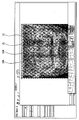
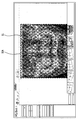
- FIG. 13A and 13B illustrate the first and second X-ray panoramic images displayed on the display screen according to the embodiment of FIG. 4 in contrast with each other.
- FIG. 14 shows another example of a display screen of the X-ray image display apparatus according to the present invention.
- FIG. 15 illustrates a process of performing an operation of the X-ray image display apparatus according to the present invention.
- 16 to 20 show another example of a display screen according to a process of performing an operation of the X-ray image display apparatus according to the present invention.
- FIG. 21 shows another example of a display screen of the X-ray image display apparatus according to the present invention.
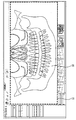
- FIG. 22 shows a comparative example of the display screen of FIG. 21.
- FIG. 1 illustrates a configuration of an X-ray image display apparatus according to an embodiment of the present invention.
- the X-ray image display apparatus includes a photographing unit 310 having an X-ray generator 311 and an X-ray sensor 312, a controller 320 having an image processing unit 322, and a viewer module 323, A storage unit 330 for storing X-ray image data and X-ray images of intermediate or final results obtained therefrom, an input unit 340 serving as a user interface, and a display unit 350 for displaying X-ray images and various necessary images. It is configured to include).
- the imaging unit 310 is provided with a driving unit 313 for moving the X-ray generator 311 and the X-ray sensor 312 in a predetermined trajectory, and the control unit 321 includes the driving unit 313 and the X-rays.
- a drive control unit 321 for controlling the operation of the generator 311 and the sensor 312 is also provided.
- the controller 320 includes a central processing unit, and is connected to the image processor 322 and the viewer module 323 as well as the storage unit 330, the input unit 340, and the display unit 350. It may be configured to manage all the actions of the X-ray image display device.
- the photographing unit 310 may represent a separate device configuration, and may be connected to the controller 320 by wire or wirelessly.
- the imaging unit 310 includes an X-ray generator 311 and an X-ray sensor 312, which are moved by a driving unit 313 to face each other with a predetermined trajectory therebetween.
- the driving unit may move the X-ray generator 311 and the X-ray sensor 312 to face the rotation axis passing between the X-ray generator 311, the X-ray sensor 312, or the X-ray generator 311 and the X-ray sensor 312.
- the rotation axis may move in one or two dimensions.
- the X-ray generator 311 irradiates X-rays toward the photographing target area and the X-ray sensor 312 passes through the photographing subject area in parallel with the above-described movement of the rotation axis.
- X-ray image data i.e., a plurality of X-ray frame data.
- X-ray image data of a plurality of frames formed by the X-ray beam irradiated at various positions and angles during the series of scan sequences reaching the X-ray sensor 312 will be referred to as a plurality of X-ray frame data hereinafter.
- the controller 320 stores the plurality of X-ray frame data obtained by the photographing unit 310 in the storage unit 330, and the image processor 322 reconstructs the first and second X-ray images using the same. .
- the viewer module 323 displays the reconstructed first and second X-ray images on the screen.
- the reconstructed first and second X-ray images may be stored in the storage unit 330 again.
- control unit 320, the storage unit 330, the input unit 340, and the display unit 350 in the X-ray image display apparatus may include a single or a plurality of computer devices and peripherals thereof. It may be implemented in the form of a device.
- the input unit 340 may be a mouse.
- the input unit 340 may include a keyboard, a keypad, a touchpad, or the like of a computer, and the type of input means is not limited thereto.
- the input unit 340 may be controlled using the illustrated input means, and may include a graphic user interface displayed on the display unit 350 through the control unit 320.
- the controller 320 includes a central processing unit (CPU) for controlling the overall operation of the X-ray image display apparatus according to the present invention.
- the controller 320 may include application specific integrated circuits (ASICs), digital signal processors (DSPs), digital signal processing devices (DSPs), programmable logic devices. At least one of programmable logic devices (PLDs), field-programmable gate arrays (FPGAs), processors, controllers, micro-controllers, and microprocessors. It can be implemented using.
- the controller 320 may also be implemented as a firmware / software module executable on the hardware platform described above. In this case, the firmware / software module may be implemented by one or more software applications in an appropriate program language.
- the viewer module 323 displays the first and second X-ray images reconstructed by the image processor 322 on the screen.
- the viewer module 323 displays the viewer module screen having a predetermined format on the display 350 according to a pre-stored algorithm, and reconstructs the first image reconstructed by the image processor 322 according to a user command input to the input unit 340.
- it can be implemented as a firmware / software module having a series of functions that properly display 2 X-ray images and provide additional functions required by a user.
- the viewer module 323 may be included as part of the image processor 322.
- the storage unit 330 is a digital data storage medium, and includes data about setting various images or parameter values for performing an operation of the X-ray image display device, as well as X-ray frame data acquired by the X-ray sensor 312; And storing X-ray image data, first and second X-ray images, etc. generated in the image processing process or reconstructed as a result of the image processing.
- the storage unit 330 may include a flash memory type storage medium such as a solid state disk (SSD), a memory card, a memory stick, or a hard disk. It may be configured to include various types of storage media, such as disk-type storage media such as disk, optical disk (Optical Disk). Some or all of the storage unit 330 may be disposed at a distance away from the control unit 320 or may be distributed in various locations. Those skilled in the art will appreciate that the implementation of the storage medium is not limited to the above examples.
- the display unit 350 is an image display device capable of outputting a viewer module screen and an X-ray image having a predetermined format.
- the display unit 350 may include various display devices such as an LCD display, an LED display, an AMOLED display, a CRT display, and particularly, may be a touch display panel.
- the input unit 340 described above includes a touch interface. can do.
- the X-ray image display apparatus configured as described above displays the first and second X-ray images that are visually different from each other on the screen of the display unit 350.
- An X-ray image is displayed, and a second X-ray image corresponding to a corresponding portion of the first X-ray image is displayed on the partial image display unit disposed in a part of the background screen display unit.
- the first and second X-ray images may be reconstructed by the image processor 322 with at least a portion of the X-ray frame data obtained through one scan sequence of the imaging unit 310, and particularly, the first X-ray image may be The X-ray tomography image or the X-ray two-dimensional image of at least one image layer, which is an arbitrary tomography plane in the photographing area, and the second X-ray image may be an X-ray tomography image of the at least one image layer in the photographing area.
- At least one of the size, position, shape, and quantity of the partial image display unit and the quantity, position, shape, angle, and thickness of the image layer of the second X-ray image may be selected by the viewer module 323.
- the second X-ray image of each image layer may be reconstructed in advance and stored in the storage unit 330.
- the first X-ray image may be an X-ray tomography image or an X-ray two-dimensional image
- the second X-ray image may be an X-ray tomography image.
- the first X-ray image is an X-ray tomography image
- the examinee wants to see the structure of the arch of a subject through the X-ray image display apparatus according to the present invention, that is, it is suitable for diagnosing an X-ray panoramic image
- the second X-ray image is an X-ray two-dimensional image
- you want to see the structure of the subject that is, X-ray cephalo is suitable for imaging.
- the X-ray image display apparatus is a first X-ray image and a first X-ray panoramic image with respect to at least one first image layer as a second X-ray image.
- a second X-ray panoramic image is provided for at least one second image layer that is at least partially different from or completely different from the first image layer with respect to a predetermined portion of the X-ray panoramic image.
- the depth resolution of the first and / or second X-ray panoramic images may be greatly improved compared to the conventional X-ray panoramic images, and the first and / or second X-ray panoramic images may be effectively used for dental care. Improves the display efficiency by providing different screen configurations.
- the X-ray image display apparatus may provide an X-ray two-dimensional image for the head as the first X-ray image and a predetermined portion of the X-ray two-dimensional image as the second X-ray image.
- An X-ray tomography image is provided for at least one image layer inside the X-ray two-dimensional image.
- the depth resolution of the X-ray tomography image can be greatly improved compared to the conventional X-ray tomography image, and a screen configuration different from the conventional method is used so that the X-ray two-dimensional image and the X-ray tomography image can be effectively used for dental or otorhinolaryngology treatment. Increase the display efficiency.
- the technical features of the present invention will be described in more detail with reference to the configuration shown in FIG. 1.
- the first and second X-ray images are classified into first and second X-ray panorama images, and when the first X-ray image is an X-ray two-dimensional image, the first and second X-ray images are counted.
- the image is divided into a Palo image and an X-ray tomography image.
- FIG. 2 schematically illustrates a scan sequence performed by the X-ray image display apparatus according to an exemplary embodiment of the present invention.
- the X-ray generator 311 and the X-ray sensor 312 rotate to face each other with the arch of the examinee interposed therebetween.
- the X-ray sensor 312 receives the X-ray beams B1, B2, B3,... Which transmit various positions in the arch at various angles, and each frame SP1, SP2, SP3,... X-ray frame data containing the X-ray light receiving signal is generated. In this way, one scan sequence is performed.
- the scan sequence is a series of processes in which the photographing unit 310 continuously moves along a predetermined movement trajectory and acquires a plurality of X-ray frame data, which is a plurality of X-ray image data obtained in units of frames from the X-ray sensor 312. It is called.
- a technique for obtaining DPRTMTJS VMFPDLA data for X-ray panoramic image reconstruction of a plurality of different image layers through one scan sequence has been presented in the prior patent publication No. 10-0917679 of the applicant.
- the one scan sequence may be configured to include the movement of the imaging unit 310 which is the same as or similar to the conventional X-ray panoramic image capturing operation.
- the width (width in the direction of movement) of the X-ray sensor 312 may be larger than the width of the X-ray sensor of the conventional X-ray panoramic image photographing apparatus.
- the width of the X-ray panoramic image capturing apparatus of the conventional X-ray sensor is about 6 mm
- the device according to the present invention employs the X-ray sensor 312 having a width of about 4 to 6 cm, thereby achieving the same photographing trajectory. Also enough data can be obtained to increase the depth resolution.
- the one scan sequence may be composed of the same or similar to the movement of the conventional CT image capture, and may be configured in various ways without being limited to the above-described examples. Those skilled in the art will understand.
- FIG. 3 is a diagram schematically illustrating a process of acquiring a plurality of X-ray frame data and performing an X-ray panoramic image reconstruction using the same according to the scan sequence of FIG. 2.
- the plurality of X-ray frame data F1 to FN may include first X-ray frame data F1 generated as the X-ray sensor 312 (refer to FIG. 2) receives the first X-ray beam B1 at the SP1 position.
- Second X-ray frame data F2 generated as a result of receiving the second X-ray beam B2 at the SP2 position, third X-ray frame data F3 as a result of receiving the third X-ray beam B3 at the SP3 position,
- the photographing unit 310 receives a plurality of X-ray beams through the X-ray sensor 312 that transmits a portion of the arch, which is the photographing target region, at various angles at various times while performing one scan sequence. It consists of X-ray image data in frame units.
- the plurality of X-ray frame data F1 to FN are stored in the storage unit 330 described above. In this case, each X-ray frame data (F1, ⁇ , FN) may be stored with information about the position and direction of the transmission of the X-ray beam in the region to be photographed.
- (b) and (c) schematically illustrate the extraction of a plurality of X-ray frame data required from the storage unit 330 to reconstruct the first and second X-ray panoramic images, respectively, in the image processor 322 described above.
- (b) illustrates a first group of X-ray frame data (F1, F3, F5, ..., FN) extracted from the plurality of X-ray frame data populations to reconstruct a first X-ray panoramic image (S21).
- (c) shows a second group of X-ray frame data (F1, F2, F4, F5) extracted from the plurality of X-ray frame data populations to reconstruct a second X-ray panoramic image different from the first X-ray panoramic image (S22).
- the X-ray frame data of the first group and the X-ray frame data of the second group among the plurality of X-ray frame data satisfy the following conditions.
- the X-ray frame data of the first group and the X-ray frame data of the second group may partially overlap each other, but are not the same, and the number of frames of the X-ray frame data of the first group and the number of frames of the X-ray frame data of the second group may not be the same. It can be the same or different from each other.
- the configuration and number of the X-ray frame data of the first group and the X-ray frame data of the second group may be appropriately adjusted according to the purpose.
- the depth resolution of the first X-ray panoramic image may be that of the second X-ray panoramic image.
- the X-ray frame data constituting the first group may be reduced.
- the number of frames may be less than the number of X-ray frame data forming the second group. This is because, in order to improve the depth resolution, a larger number of X-ray frame data acquired at a larger angle range is required for each part of the arch, which is a photographing area.
- certain X-ray frame data may be selectively selected for reconstruction of the first X-ray panoramic image (s21) or for reconstruction of the second X-ray panoramic image (s22).
- first group and the second group are extracted and configured as described above may vary depending on the characteristics of the first and second image layers, which are the focal regions of each of the X-ray panoramic images. Issues relating to the first and second image layers will be discussed in more detail later.
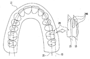
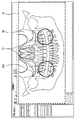
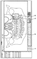
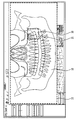
- FIG. 4 shows an example of a display screen of the X-ray image display apparatus according to the present invention.
- a background image display unit 11 for displaying a first X-ray panoramic image 10 which is an X-ray panoramic image of at least one first image layer is provided. At least one part disposed in a predetermined part in the background image display unit 11 and corresponding to the predetermined part, including at least one of the first image layers or at least a part that is different from or completely different from the first image layer; A partial image display unit 21 is provided to display a portion of the second X-ray panoramic image 20 which is an X-ray panoramic image of the second image layer.
- One or more than one partial image display unit 21 may be provided.
- the size, position, shape or quantity of the partial image display unit 21 may be adjusted according to a user's input, for example, through a mouse input.
- the partial image display unit 21 since the partial image display unit 21 is provided to enhance the efficiency of diagnosis by reinforcing the depth resolution of the first X-ray panoramic image 10, the partial image display unit 21 includes a portion that needs to be checked for various depths among the teeth of the examinee. It is preferable. For example, in the case of the maxillary arch, it is preferable to include a maxillary molar that is disposed on each of the outer and inner sides of the tooth and requires confirmation thereof.
- the partial image display unit 21 first checks the first X-ray panoramic image 10 provided by the user (eg, a dentist) through the background image display unit 11, and needs further review of a predetermined portion.
- the second X-ray of the above-mentioned second image layer selectively activated according to a user's command and superimposed on the first X-ray panoramic image of the portion or replacing the first X-ray panoramic image of the portion.
- the corresponding part of the panoramic image 20 may be displayed.
- the second X-ray panoramic image 20 may be displayed with different brightness or color than the first X-ray panoramic image 10.
- by displaying the edge of the partial image display unit 21 on the screen it is possible to indicate a boundary between the first X-ray panoramic image 10 and the second X-ray panoramic image 20.
- the image processor reconstructs the first X-ray panoramic image of the at least one first image layer from the X-ray image data of the plurality of frames acquired by the photographing unit through a single scan sequence.
- the second X-ray panoramic image 20 is reconstructed and provided to the viewer module for at least one second image layer which is at least partially different from or completely different from at least a portion of the first image layer. do.
- the image processor may reconstruct and store the first and second X-ray panoramic images of the first and second image layers in advance.
- the scan sequence refers to a series of processes in which the photographing unit continuously moves along a predetermined movement trajectory and acquires X-ray image data of a plurality of frames from different angles.
- One scan sequence may be configured by a movement of the imaging unit 310 that is the same as or similar to a conventional X-ray panoramic image capturing operation, or may be different from that.
- the one scan sequence may be composed of the same or similar movement of the imaging unit, or may be different from the conventional CT imaging operation. That is, when a plurality of X-ray image data photographed from various angles with respect to the archery can be obtained so that the first and second X-ray panoramic images, which will be described later, can be reconstructed, the operation of the photographing unit may be varied during one scan sequence.
- the width (width in the direction of movement) of the X-ray sensor is preferably larger than the width of the X-ray sensor of the conventional X-ray panoramic imaging apparatus.
- the X-ray sensor width of the conventional X-ray panoramic image photographing apparatus is about 6 mm
- the device according to the present invention employs an X-ray sensor whose width is larger than that of a general X-ray sensor, preferably 10 mm or more.
- X-ray image data having an angular range sufficient to increase depth resolution of the first and / or second X-ray panoramic image may be acquired.
- the height of the X-ray sensor of the Panomara imaging device may vary according to the desired panorama shooting area or the X-ray panoramic image size, but it is difficult to specify a specific range, but it is generally between 100 mm and 200 mm, and the width of the X-ray sensor is also used to scan the image.
- the present invention may be variously adjusted according to a sequence, but in the present invention, assuming that the scan sequence is similar to that of a general X-ray panoramic imaging apparatus, in order to obtain X-ray image data having a larger angle range, the width of the general X-ray sensor may be 10 mm or more. Preferably, it is 18 mm or more.
- the first X-ray panoramic image is an X-ray panoramic image of at least one first image layer, and the X-ray panoramic image of an X-ray panoramic image of one image layer or the X-ray panoramic image of two or more different image layers is superimposed.
- the X-ray panoramic image of an X-ray panoramic image of one image layer or the X-ray panoramic image of two or more different image layers is superimposed.
- the second X-ray panoramic image is an X-ray panoramic image of at least one second image layer which is at least partially different from or completely different from at least part of the first image layer or at least one of the first image layers.
- the second X-ray panoramic image may be an X-ray panoramic image or a first X-ray panoramic image of any one image layer different from the first image layer of the first X-ray panoramic image.
- An X-ray panoramic image overlapping an X-ray panoramic image of the first image layer and at least one other image layer or an X-ray panoramic image of two or more image layers different from the first image layer of the first X-ray panoramic image
- the second X-ray panoramic image may be an X-ray panoramic image, and when the first X-ray panoramic image is an X-ray panoramic image in which X-ray panoramic images of two or more different image layers overlap each other, the second X-ray panoramic image may be any one of the first image layers of the first X-ray panoramic image.
- the first X-ray panoramic image may display relatively wide information along the X-ray irradiation direction by overlapping X-ray panoramic images of the plurality of first image layers
- the second X-ray panoramic image may be the first X-ray panoramic image.
- the image may be an X-ray panoramic image of the second image layer corresponding to any one of the first image layers.
- the X-ray panoramic image of each image layer may be an X-ray panoramic image of the same magnification that expresses the same range in the same plane at the same magnification, and superposition means pixel values of the X-ray panoramic image for each image layer along the X-ray irradiation direction. Adding, averaging, or taking a representative value may mean displaying a single X-ray panoramic image in which all of the X-ray panoramic images of the respective image layers are substantially reflected.
- the first and second X-ray panoramic images may be X-ray panoramic images having visually different depth resolutions through selection and combination of X-ray panoramic images for a plurality of image layers, and may be freely selected according to a user's purpose. have.
- the number, thickness, angle, shape, position, etc. of the first and second image layers for the first and second X-ray panoramic images may be adjusted according to a user's purpose. The case where the first and second image layers are different from each other will be described.
- the image layer of the X-ray panoramic image includes a focus curve that is a reference for focusing when reconstructing the X-ray panoramic image. Therefore, not only the structure on the focal curve but also the structures existing in the front and rear predetermined areas of the focal curve in the X-ray irradiation direction are projected on the X-ray panoramic image of an image layer. However, there is a difference in the degree of clarity of the structure on the focal curve and the structure within a certain distance before and after the thickness of the image layer, where the relative difference is expressed by the thickness of the image layer.
- the relatively thin thickness of the image layer means that the front and rear regions of the focal curve, which are clearly projected on the X-ray panoramic image relative to the focal surface, are relatively narrow with respect to the X-ray irradiation direction, which is the depth of the X-ray panoramic image. This means that the resolution is relatively high.
- the thickness of the image layer is relatively expressed, and the thickness on the drawing does not represent the absolute thickness.
- the thickness of the second image layer may be thinner than the thickness of the first image layer.
- the depth resolution of the second X-ray panoramic image is better than that of the first X-ray panoramic image.
- the image processing apparatus may use X-ray image data having a wider angle range passing through each point for each point of the second image layer when reconstructing the second X-ray panoramic image.
- the thicknesses of the first and second image layers may be the same thickness relatively thinner than those of the general X-ray panoramic image, and the depth resolution of the first and second X-ray panoramic images may be higher than that of the general X-ray panoramic image. Details for increasing the depth resolution of the first and / or second X-ray panoramic image by adjusting the thickness of the first and / or second image layer will be described in detail with reference to FIG. 10 and related descriptions.
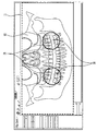
- FIG. 5 shows an example of the first and second image layers of the first and second X-ray panoramic images displayed on the display screen according to the embodiment of FIG. 4.
- FIG. 1 illustrates an example of the first image layer 15 and the second image layer 25 described above in the shape of the maxillary arch 12 which is a part of the region of interest of the X-ray panoramic image.
- the X-ray panoramic image of the first image layer 15 may be the first X-ray panoramic image 10 of FIG. 1, and the X-ray panoramic image of the second image layer 25 is the second X-ray panoramic image. (20).
- the quantities, angles, shapes, positions, etc. of the first and second image layers 15 and 25 are merely examples and may be different from those of the X-ray panoramic image shown in FIG. 4.
- At least one of the quantity, angle, shape, and position of the second image layer 25 is different from that of the first image layer 15.
- the shape refers to the overall shape according to the curvature of the various parts of the image layer.
- the shape of the second maxillary molar 2M and the first and second image layers 15 and 25 passing therethrough are three-dimensionally enlarged.
- the second maxillary molars (2M) two roots (2MR) are often present on the outer side of the arch, that is, the part close to the lips, and one root (2MR) exists on the inner side of the arch, that is, the part close to the tongue. do. Accordingly, two roots 2MR are seen in the first X-ray panoramic image reconstructed by focusing the first image layer 15, but one root is present in the second X-ray panoramic image reconstructed by focusing the second image layer 25. 2MR) is shown.
- the second X-ray panoramic image of the second image layer 25 provides X-ray panoramic image information on an image layer having a different quantity, angle, shape, and position than the first X-ray panoramic image.
- first and / or second image layers 25 may have at least one of a quantity, a shape, a position, and an angle. It may be provided as a plurality of other image layers, and the quantity, angle, shape, position, etc. of the first and second image layers 15 and 25, in particular, the second image layer 25 may be variously changed according to a user's selection.
- the user's selection may be input to the viewer module through the input unit, and the viewer module displays a control menu for inputting the user's selection on the screen to display the second X-ray panoramic image according to the user's selection. Can be.
- FIG. 6 illustrates another example of the first and second image layers of the first and second X-ray panoramic images displayed on the display screen according to the embodiment of FIG. 4.
- the first image layer 15a may be relatively thicker than the second image layer 25a. This means that information about the internal structure of a relatively thicker image layer, that is, a relatively large area with respect to the X-ray irradiation direction, is superimposed on the first X-ray panoramic image in plan view.
- the number, angle, shape, and position of the first image layer 15a and the second image layer 25a may not only be different, but may also be different from each other.
- the second image layer 25a may partially or completely overlap the first image layer 15a or may be completely different from the first image layer 15a.
- first and / or second image layers 25a may have a quantity, shape, position, angle, and thickness. At least one of the plurality may be provided as a plurality of other image layers, and the quantity, angle, shape, and position of the first and / or second image layers 15a and 25a, in particular, the second image layer 25a may be selected according to a user's selection.
- the thickness and the like can be variously changed.
- FIG. 7 illustrates another example of the first and second image layers of the first and second X-ray panoramic images displayed on the viewer module screen according to the embodiment of FIG. 4.
- the first image layer 15b and the second image layer 25b overlap with each other as a whole, and the first image layer 15b is thicker than the second image layer 25b. It can be thick.
- the first image layer 15b of the first X-ray panoramic image may be set to have a thickness larger than that of the second image layer, for example, a thickness including most of the thicknesses of the teeth arranged along the arch path.
- the second image layer 25b of the X-ray panoramic image has a thinner thickness in the first image layer, whereby the second X-ray panoramic image provides an X-ray panoramic image that is sharper than the first X-ray panoramic image, that is, has improved depth resolution. can do.
- the first X-ray panoramic image is substantially thick by overlapping the X-ray panoramic image of a plurality of thinner image layers or an X-ray panoramic image of one thicker image layer.
- the shape of an X-ray panoramic image of one image layer may also be shown.
- the second X-ray panoramic image may be one of a plurality of overlapping X-ray panoramic images for reconstruction of the first X-ray panoramic image.
- the X-ray panoramic image of each image layer may exhibit the same magnification, and as a result, the first and second X-ray panoramic images may exhibit the same magnification.
- a single X-ray panoramic image may be realized by overlapping X-ray panoramic images of a plurality of image layers.
- the X-ray image processing apparatus according to the present invention may be relatively thicker than a conventional X-ray panoramic image.
- An X-ray panoramic image may be provided for an image layer. That is, the X-ray image processing apparatus according to the present invention may freely adjust the thickness of the image layer of the X-ray panoramic image, and thereby may freely adjust the depth resolution of the X-ray panoramic image.
- the second image layer 25b includes a portion having a high frequency of tomography imaging during dental treatment, thereby providing prompt and convenient treatment. It would be possible to increase the exposure and significantly reduce the X-ray exposure of the subject. Meanwhile, even in this case, the number of the first and / or second image layers 15b and 25b is not limited to one, but may be a plurality, and the first and / or second image layers 15b and 25b may be particularly selected by the user.
- the two image layer 25b may be variously changed.
- FIG. 8 illustrates an example of a first image layer of a first X-ray panoramic image displayed on a display screen according to the embodiment of FIG. 4.
- the first X-ray panoramic image is divided into a plurality of image layers, that is, multiple image layers, in the same section, and by selecting and connecting the sharpest section image layer for each section, the X-ray panorama that is relatively sharply autofocused for the entire section is relatively sharp. It may be an image.
- the first image layer may be connected discontinuously or continuously by varying the position of each of the plurality of sections divided along the longitudinal direction of the arch form.
- the arbitrary image layer 151 is first shown in the figure.
- the arbitrary image layer may be a reference image layer determined by the photographing trajectory of the device.
- Reference numeral 151F denotes a photographing target region 151F of the X-ray panoramic image.
- the X-ray image display apparatus reconstructs an X-ray panoramic image of an inner image layer 152 located inside an arbitrary image layer 151 in the region to be photographed, and within the region to be photographed.
- the X-ray panoramic image is also reconstructed with respect to the outer image layer 153 located outside the arbitrary image layer 151.
- the X-ray panoramic image of the arbitrary image layer and the X-ray panoramic image of the inner and outer image layers may be reconstructed separately, that is, different X-ray image data, and the X-ray panoramic image of the arbitrary image layer may be It is also possible to reconstruct the X-ray panoramic image of the inner and outer image layers using the X-ray image data.
- the latter specific method may be referred to Korean Patent Publication No. 10-0917679 by the present applicant, and the former specific method may be referred to FIG. 10 and related description.
- the reconstructed image may complete a first X-ray panoramic image in which a plurality of different X-ray panoramic images are connected for each horizontal section.
- the first image layer 15c includes, for example, a first segment F1 including anterior teeth and a canine.
- the inner image layer 152, the optional image layer 151, and the outer image layer 153 are discontinuous or continuous with each other for the second section F2 and the third section F3 including the posterior tooth. It is connected by the form. For reference, interpolation or the like may be used to connect the image layers for each section to obtain a continuous final image layer.
- Korean Patent Application Publication No. 10-1094180 a method of obtaining one final image layer with a plurality of image layers for each section and obtaining an X-ray panoramic image by reconstructing an X-ray panoramic image of the final image layer.
- the X-ray panoramic images of the plurality of image layers may be reconstructed separately from each other, that is, different X-ray image data, and may be reconstructed using the X-ray image data of the X-ray panoramic image of the arbitrary image layer. It may be.
- the latter specific method may be referred to Korean Patent Publication No. 10-0917679 by the present applicant, and the former specific method may be referred to FIG. 10 and related description.
- the number of divided sections and the number of preset image layers are simplified to three.
- the unit sections for performing autofocusing operations are divided into a larger number of sections along the longitudinal direction of the arch form. Not only can it be subdivided, but it can also be subdivided into multiple regions in the height direction of the teeth perpendicular to the drawing.
- the number of image layers preset inward and outward of the arbitrary image layer 151 may be larger.
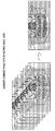
- FIG. 9 illustrates another example of the first X-ray panoramic image displayed on the display screen according to the embodiment of FIG. 4.
- the first X-ray panoramic image may be an X-ray panoramic image reconstructed into the clearest block image or a combination of block image data by comparing the X-ray panoramic images of the plurality of image layers or the image data of the plurality of image layers in units of blocks.
- the first image layer may be a combination of block unit image layers selected from a plurality of image layers.
- an X-ray panoramic image of a plurality of image layers is shown on the left side of the drawing.
- the X-ray panoramic images of the plurality of image layers may be reconstructed separately, that is, different X-ray image data, and the X-ray panoramic images of the plurality of image layers may be reconstructed using the X-ray image data of the X-ray panoramic image of the arbitrary image layer. It is also possible to reconstruct an X-ray panoramic image.
- the latter specific method may be referred to Korean Patent Publication No. 10-0917679 by the present applicant, and the former specific method may be referred to FIG. 11 and related description.
- the X-ray panoramic images of the plurality of reconstructed image layers are reconstructed into X-ray panoramic images of the same scale, that is, the same magnification, and the X-ray panoramic images are partitioned into a block set composed of unit blocks of the same number and the same size, and then frequency.
- the block image with the clearest image of each unit block is selected.
- the first X-ray panoramic image on the right side may be obtained by combining the block images.
- the first X-ray panoramic image corresponds to a combination of block-by-block X-ray panoramic images of an image layer in a block unit closest to the arch path of the actual subject over the entire block.
- the block image is selected from the X-ray panoramic images of the plurality of image layers.
- the block image data may be selected from the X-ray panoramic image data of the plurality of image layers.
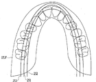
- FIG. 10 illustrates an example of a second image layer of a second X-ray panoramic image displayed on the display screen according to the embodiment of FIG. 4.
- the second image layers 251, 252, and 253 may be one or more. Meanwhile, the second image layers 251, 252, and 253 may be preset and stored in the image processing apparatus.
- the plurality of second image layers 251, 252, 253 may include any image layer 251 and its inner and outer image layers.
- the plurality of second image layers 251, 252, and 253 may be set not to cross each other. In this case, the second image layers 251, 252, and 253 may be reconstructed separately from each other, that is, different X-ray image data, or may be reconstructed into X-ray image data for an arbitrary image layer.
- FIG. 11 illustrates a range of X-ray image data used for reconstruction of the first X-ray panoramic image and the second X-ray panoramic image.
- the following description of FIG. 11 is an example of implementing the first and second image layers, which may be applied to the first and second image layers described above with reference to FIGS. 5 to 10.
- the X-ray image display apparatus stores a plurality of frame X-ray image data obtained by the X-ray sensor through a single scan sequence in a storage unit, and stores the X-ray panoramic image of an arbitrary image layer. After extracting the X-ray image data necessary for reconstruction from the storage unit, the X-ray panoramic image may be reconstructed by direct back projection (DBP) to the arbitrary image layer. This is contrasted with the shift-and-add method which implements an image layer by superimposing conventional X-ray image data.
- DBP direct back projection
- the X-ray image data required for reconstruction of the X-ray panoramic image for the arbitrary image layer may be X-ray image data having a predetermined angle passing through each point of the image layer, and if necessary, transmits each point of the arbitrary image layer. Some of the X-ray image data having a predetermined angle range may be calculated through interpolation of other X-ray image data.
- the depth resolution of the X-ray panoramic image may vary depending on the angle range of the X-ray image data passing through each point of the image layer.
- any point in an image layer if only one angle of X-ray image data is utilized, then all structures on the path of X-ray progression at that angle overlap only one plane, i.e. only X-ray image without depth resolution. You can get it. However, if X-ray image data of various angles are used for the corresponding point, X-ray panoramic image with improved depth resolution, that is, X-ray panoramic image with thinner thickness of the image layer in the X-ray transmission direction can be obtained. As the angular range of X-ray image data passing through each point increases, the depth resolution is improved.
- the first image layer 15 is, for example, an arbitrary image layer
- reference numeral 15F denotes a photographing target area.
- the X-ray image display apparatus reconstructs the first X-ray panoramic image by using X-ray image data having a predetermined angle range passing through each of the points of the first image layer 15. For example, X-ray image data in the range of angle ⁇ 1a may be used for a point a on the first image layer 15, and X-ray image data in the angle ⁇ 1b range may be used for a b point.
- the second image layer 25 is set to pass along the inside of the first image layer 15 side by side as an example.
- the X-ray image display apparatus reconstructs the second X-ray panoramic image by using X-ray image data having a predetermined angle range passing through each of the points on the second image layer 25.
- X-ray image data having an angle ⁇ 2a ' may be used for a' point on the second image layer 25
- X-ray image data having an angle ⁇ 2b ' may be used for a b' point.
- the point 'a' may be a point at which the normal line passing through the point a in the first image layer 15 intersects the second image layer 25. That is, point a 'and point a follow the same X-ray irradiation direction.
- the point b ' may be a point at which the normal line passing through the point b in the first image layer 15 intersects the second image layer 25. That is, point b 'and point b follow the same X-ray irradiation direction.
- ⁇ 1a and ⁇ 2a ', and ⁇ 1b and ⁇ 2b' have a relationship of ⁇ 1a ⁇ 2a 'and ⁇ 1b ⁇ 2b'.
- the second X-ray panoramic image of the second image layer 25 has a relatively better depth resolution than the first X-ray panoramic image of the first image layer 15.
- the second image layer 25 has a relatively thinner thickness than the first image layer 15.
- the first and second image layers 15 and 25 may have the same trajectory, but since the thicknesses are different from each other, the first and second image layers 15 and 25 may be visually displayed as different X-ray panoramic images.
- the X-ray image display apparatus obtains X-ray image data having a predetermined angle range passing through each point of a certain image layer from X-ray image data of multiple frames having different angles, and transmits the X-ray image data having a predetermined angle range passing through each point.
- the X-ray panoramic image of the corresponding image layer may be reconstructed by directly post-projecting the X-ray image data of each image point into an arbitrary image layer.
- any image layer may be freely selected by the user regardless of external factors such as the photographing trajectory of the device, the angle, the position, the shape, and the like.
- the thickness of the image layer can also be freely selected according to the angular range. Since this can be applied to both the first and / or second X-ray panoramic image reconstruction, the depth resolution of the first and / or second X-ray panoramic image can also be freely adjusted. .
- both the second X-ray panoramic image may have a better depth resolution than the existing X-ray panoramic image, and both the first and second X-ray panoramic images may have a lower depth resolution than the existing X-ray panoramic image. That is, depth resolution of the first and second X-ray panoramic images may be entirely determined by a user's selection.
- FIG. 12 illustrates an alignment relationship between a first X-ray panoramic image and a second X-ray panoramic image.
- first X-ray panoramic image is shown as one and the second X-ray panoramic image is shown as two.
- the second X-ray panoramic images 201 and 202 are stored as X-ray panoramic images having the same magnification of the same frame size, representing the same extent in plan view as the first X-ray panoramic image 10.
- the display screen illustrated in FIG. 4 only the portions 211 and 212 corresponding to the partial image display unit 21 are displayed on the screen in the second X-ray panoramic images 201 and 202.
- portions 211 and 212 corresponding to the partial image display unit 21 in one or more second X-ray panoramic images may be displayed in the partial image display unit 21 in the first X-ray panoramic image 10.
- which of the second X-ray panoramic images 201 and 202 is displayed on the partial image display unit 21 may be determined by a user's selection.
- FIG. 13A and 13B illustrate the first and second X-ray panoramic images displayed on the display screen according to the embodiment of FIG. 4 in contrast with each other.
- FIG. 13A and 13B illustrate a first X-ray panoramic image 10A and FIG. 13A according to a user's input of an image in the partial image display unit 21 while the image displayed on the background image display unit 11 is maintained for convenience. Or a corresponding partial image in the second X-ray panoramic image 20A (see FIG. 13B). 13A and 13B, the difference between the two partial image display units 21 indicated by the arrow on the left side can be easily found.
- the first X-ray panorama also appears in the partial image display unit 21.
- the corresponding part of the image 10A is displayed so that the root of the maxillary molar is seen as one
- FIG. 13B the corresponding part of the second X-ray panoramic image 20A is displayed on the partial image display unit 21 on the same side to display the root of the maxillary molar. Two roots can be seen.
- the user may display the second X-ray panorama displayed on the partial image display unit 21 through an input action such as turning the mouse wheel forward or backward as an example of the input unit while the partial image display unit 21 is activated.
- the second image layer of the image may be selected.
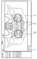
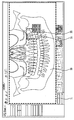
- FIG. 14 shows another example of a display screen of the X-ray image display apparatus according to the present invention.
- the indicator display unit 31 indicating which image layer is represented by the second X-ray panoramic image 20 displayed on the partial image display unit 21 on the display screen is compared with the embodiment of FIG. 4. The difference is that it includes more.
- the indicator display unit 31 may determine the quantity, thickness, angle, and shape of the first image layer 15 of the first X-ray panoramic image 10 and / or the second image layer 25 of the second X-ray panoramic image 20. , Position, etc. may be represented by at least one of numbers, pictures, and figures, and the user may intuitively recognize the relative relationship between the first and second image layers of the first and second X-ray panoramic images displayed on the display screen. have.
- the indicator display unit 31 shows that the image layer 35 indicated by the reference numeral 35 is displayed on the partial image display unit 21 as an example.
- the X-ray image display apparatus includes a partial or first image layer including at least one of a first X-ray panoramic image and a first image layer for at least one first image layer through a display screen. And simultaneously show a portion of the second X-ray panoramic image for at least one second image layer that is at least partially different or completely different.
- the first and second X-ray panoramic images have the same magnification, the relative positions with respect to the arch are aligned and displayed, and the second X-ray panoramic image shows only a part of the second X-ray panoramic image, but overlaps or partially overlaps the first X-ray panoramic image. May be displayed instead.
- FIG. 15 illustrates a process of performing an operation of the X-ray image display apparatus according to the present invention.
- X-ray imaging s10 by the imaging unit is performed.
- the movement of the photographing part may include a series of continuous motions (the direction of the movement is not limited to one direction such as the direction of rotation) while the X-ray generator and the X-ray sensor are turned to face each other with the subject interposed therebetween. Can be.
- the operation of the X-ray generator and X-ray sensor synchronized with this movement constitutes one scan sequence.
- X-ray image data of a plurality of frames obtained through the scan sequence is stored in the storage unit.
- the X-ray image data of the plurality of frames may include information such as the position and direction through which the X-ray beam forming each frame has passed through the subject.
- the image processor performs reconstruction of the first X-ray panoramic image (s21) and reconstruction of the second X-ray panoramic image (s22).
- the image processor extracts the data necessary for each X-ray panoramic image from the X-ray image data of the plurality of frames stored in the storage unit to reconstruct the first and second X-ray panoramic images, in particular, the first and / or enhanced depth resolution.
- the process of reconstructing the second X-ray panoramic image is the same as described above with reference to FIG. 9.
- the first and second X-ray panoramic images reconstructed by the image processor are also stored in the storage unit.
- the viewer module displays the first X-ray panoramic image on the background image display (s30). In this case, it is determined whether a user requests a second X-ray panoramic image of a partial region of the first X-ray panoramic image through an input unit (S40), and the second X-ray panoramic image of the partial region is determined by the first X-ray panoramic image.
- the image may be displayed simultaneously with the image (s52).
- the process of determining whether to request the second X-ray panoramic image (s40) may be omitted.
- a process (s51) of selecting a position, an angle, a quantity, or a thickness of the second image layer to be displayed as the second X-ray panoramic image may be performed prior to the display of the second X-ray panoramic image.
- a process (s51) of selecting a position, an angle, a quantity, or a thickness of the second image layer to be displayed as the second X-ray panoramic image may be performed.
- the second X-ray panoramic image of the two image layers may be displayed together with the first X-ray panoramic image (s52).
- 16 to 20 show another example of a display screen according to a process of performing an operation of the X-ray image display apparatus according to the present invention.
- the viewer module may provide a background image display unit 11 displaying the first X-ray panoramic image 10 on a display screen, and display the first X-ray panoramic image 10 thereon.
- the first X-ray panoramic image 10 may be an image in which X-ray panoramic images of multiple image layers having the same magnification are superimposed.
- the partial image display unit 21 may be activated in a predetermined portion of the first X-ray panoramic image 10, and the second X-ray panoramic image 20 may be displayed thereon.
- the second X-ray panoramic image 20 corresponds to a predetermined portion of the first X-ray panoramic image 10 and overlaps or replaces a predetermined portion of the first X-ray panoramic image 10.
- the user may freely move and adjust the position of the partial image display unit 21 and may adjust the size of the partial image display unit 21.
- 18 illustrates adjusting the size of the partial image display unit 21 according to a user's selection.
- the viewer module displays the second X-ray panoramic image 20 for the corresponding portion of the first X-ray panoramic image 10 on the partial image display unit 21 in real time.
- the second X-ray panoramic image 20 may be an X-ray panoramic image of any one of a plurality of image layers of the first X-ray panoramic image 10, and in this case, the viewer module may include a partial image display unit ( A second X-ray panoramic image 20 that can be displayed on the partial image display unit 21 on one side of the 21, that is, the current partial image display unit 21 compared to the X-ray panoramic image superimposed on the first X-ray panoramic image 10. An indicator indicating a relative positional relationship of the second X-ray panoramic image 20 displayed in FIG. 9 may be displayed.
- 20/40 shown in the drawing represents a total of 40 X-ray panoramic images superimposed on the first X-ray panoramic image 10.
- the 2 X-ray panoramic image 20 indicates that it is 20th of them.
- the area indicated by the red squares increases the number of X-ray panoramic images superimposed on the first X-ray panoramic image 10, and indicates the relative position of the second X-ray panoramic image 20 displayed on the current partial image display unit 21. Is displayed.
- the viewer module may switch the second X-ray panoramic image 20 displayed on the partial image display unit 21 in response to a user rotating the mouse wheel.
- FIG. 19 illustrates that the second X-ray panoramic image 20 displayed on the partial image display unit 21 is switched by a user's manipulation in the state of FIG. 18, and the 40 X-ray panoramic images superimposed on the first X-ray panoramic image 10 are illustrated.
- the X-ray panoramic image of the 14th image layer is displayed as the second X-ray panoramic image 20.
- FIG. 17 it can be seen that the second X-ray panoramic image 20 is changed, which means that the second image layer of the second X-ray panoramic image 20 is changed.
- the viewer module may provide a capture screen 20c of the second X-ray panoramic image 20 displayed on the partial image display unit 21 according to a user's manipulation such as a double click.
- 20 illustrates a corresponding function, in which the capture screen 20c of the second X-ray panoramic image 20 of the first portion is displayed in association with the first portion, and the partial image display unit 21 is operated by a user operation.
- the second X-ray panoramic image 20 is displayed at another position.
- the capture screen 20c may be stored as a separate image file.
- the first X-ray image of the X-ray image display apparatus according to the present invention is an X-ray cephalo image
- the differences from the above description will be described.
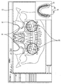
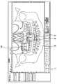
- FIG. 21 shows another example of a display screen of the X-ray image display apparatus according to the present invention. Reference is made in conjunction with FIG. 4.
- a background screen display unit 11 displaying an X-ray cephalo image as the first X-ray image 50A is provided.
- Partial image which displays a part of the X-ray tomography image for at least one image layer in the X-ray cephalo image as the second X-ray image 60A disposed on a predetermined portion in the background screen display unit 11 and corresponding to the predetermined portion.
- the display portion 21 is provided.
- One or more partial image display units 21 may be provided, and according to a user's input, for example, the size, position, shape or quantity of the partial image display unit 21 may be provided through a mouse input through the input unit 340. If the user checks the X-ray cephalo image provided through the background screen display unit 11 and determines that further review of the predetermined part is necessary, the user may selectively activate the part according to the user's command. A corresponding portion of the X-ray tomography image for any image layer in the X-ray cephalo image may be displayed by superimposing the X-ray cephalo image or by replacing the X-ray cephalo image thereof. In addition, by displaying the edge of the partial image display unit 21 on the screen, it is possible to indicate the boundary between the X-ray cephalo image and the X-ray tomography image.
- the X-ray cephalo image and the X-ray tomography image may be reconstructed with at least some of a plurality of X-ray frame data obtained through one scan sequence of the X-ray generator 311 and the X-ray sensor 312, respectively. At least a portion of the first group X-ray frame data for the X-ray cephalo image and the second group X-ray frame data for the X-ray tomography image may be different among the plurality of X-ray frame data.
- the X-ray generator 311 and the X-ray sensor 312 irradiate and receive X-rays while moving along a predetermined trajectory with the head of the subject, that is, the photographing target area therebetween.
- the X-ray generator 311 and the X-ray sensor 312 may irradiate and receive an X-ray beam that passes through the entire photographing region, or may radiate and receive an X-ray beam that transmits through a portion of the photographing region.
- the 311 and the X-ray sensor 312 move along a predetermined trajectory by the driver 313 to acquire X-ray frame data in multiple directions, thereby including a plurality of first and second group X-ray frame data through a scan sequence. Secure X-ray frame data.
- a plurality of X-ray frame data is stored in the storage 330.
- the image processor 322 reconstructs the X-ray cephalo image and the X-ray tomography image from the first and second group X-ray frame data of at least some of the plurality of X-ray frame data, and stores them in the storage 330.
- the X-ray cephalo image and the X-ray tomography image may exhibit the same magnification.
- the image processor 322 connects the X-ray frame data in the same direction passing through the entire area to be photographed or the X-ray frame data in the same direction passing through a portion of the area to be photographed to the entire photographing area.
- the multi-directional X-ray frame data passing through the at least one image layer may be reconstructed into a predetermined tomography synthesis algorithm for the X-ray tomography image.
- the image processor 322 may reconstruct and store the plurality of X-ray tomography images shown through the partial image display unit in the storage unit 330 according to a user's selection.
- the image processor 322 may implement an X-ray cephalo image by reconstructing an X-ray tomography image of a plurality of image layers corresponding to substantially the entire photographing area and overlapping the same direction.
- the X-ray cephalo image may have a depth resolution. X-ray cephalo image that connects X-ray frame data in the same direction that passes through the entire area to be photographed or X-ray frame data in the same direction that passes through a portion of the area to be photographed to the entire area There is no gain of separation.
- the image processing unit 322 secures X-ray frame data in multiple directions passing through at least one image layer for X-ray tomography images, and converts X-ray image data having a predetermined angle range through each point of the image layer into the corresponding image layer.
- Post-projection can be used to reconstruct an X-ray tomography image.
- some of the X-ray image data having a predetermined angle range passing through each point of the image layer may be calculated through interpolation of other X-ray image data.
- the X-ray tomography image reconstructed in this manner is a general tomography synthesis algorithm. Depth resolution compared to the X-ray tomography image can exhibit excellent characteristics.
- the viewer module 323 displays the reconstructed X-ray cephalo image on the background image display unit 11 and displays the reconstructed X-ray tomography image on the partial image display unit 21.
- the X-ray tomography image may be displayed based on an arbitrary image or a user's selection. That is, before the display of the X-ray tomography image or after the display of the arbitrary X-ray tomography image, the user may select the position, angle, quantity or thickness of at least one image layer, and the viewer module 322 may select an image according to the user's selection.
- the X-ray tomography image for the layer is displayed or changed on the partial image display unit 21.
- the viewer module 322 may adjust the size, position, shape, or quantity of the partial image display unit 21 according to a user's selection, and if necessary, display an indicator indicating a relative positional relationship of the X-ray tomography image in the X-ray cephalo image. I can display it.
- the image layer of the X-ray tomography image may pass through or near the maxillary sinus.
- X-ray cephalo image is often used to diagnose the head structure and to diagnose the maxillary sinus and nearby tissues in the diagnosis of otolaryngology. Due to the characteristics of the X-ray 2D image, the skull overlaps to detect the maxillary sinus and its partial tissue. Difficult to identify
- FIG. 22 is a comparative example of the display screen of FIG. 21 and shows only the first X-ray image, that is, the X-ray cephalo image, on the background image display unit 11.
- the X-ray cephalo image is displayed by overlapping skulls due to the characteristics of the X-ray two-dimensional image, which is the same in the maxillary sinus.
- the X-ray tomography image of the partial image display unit 21 of FIG. 21 it can be seen that the superposition of the skull is removed from the maxillary sinus.
- the X-ray image display apparatus enables the head structure to be identified through the X-ray cephalo image displayed on the background image display unit 11, and the X-rays for the maxillary sinus and the portion displayed on the partial image display unit 21.
- the tomography images can provide X-ray images more suitable for diagnostic purposes.
- the X-ray cephalo image and the X-ray tomography image provided through the X-ray image display apparatus according to the present invention are not limited thereto.
- the X-ray image processing apparatus may provide various functions for user convenience, all of which are applied to the technical spirit of the present invention, and are included in the scope of the present invention.
- the present invention relates to an X-ray image display apparatus and a method thereof, and may be used in an X-ray panoramic image display apparatus and an X-ray imaging apparatus including the same.
Landscapes
- Health & Medical Sciences (AREA)
- Life Sciences & Earth Sciences (AREA)
- Engineering & Computer Science (AREA)
- Medical Informatics (AREA)
- Physics & Mathematics (AREA)
- General Health & Medical Sciences (AREA)
- Pathology (AREA)
- Veterinary Medicine (AREA)
- Animal Behavior & Ethology (AREA)
- Biophysics (AREA)
- High Energy & Nuclear Physics (AREA)
- Surgery (AREA)
- Nuclear Medicine, Radiotherapy & Molecular Imaging (AREA)
- Optics & Photonics (AREA)
- Public Health (AREA)
- Radiology & Medical Imaging (AREA)
- Biomedical Technology (AREA)
- Heart & Thoracic Surgery (AREA)
- Molecular Biology (AREA)
- Dentistry (AREA)
- Oral & Maxillofacial Surgery (AREA)
- Human Computer Interaction (AREA)
- Theoretical Computer Science (AREA)
- Computer Vision & Pattern Recognition (AREA)
- Pulmonology (AREA)
- General Physics & Mathematics (AREA)
- Signal Processing (AREA)
- Multimedia (AREA)
- Apparatus For Radiation Diagnosis (AREA)
Priority Applications (5)
| Application Number | Priority Date | Filing Date | Title |
|---|---|---|---|
| EP17807990.1A EP3329852B1 (en) | 2016-10-18 | 2017-10-18 | X-ray image display device |
| JP2019520778A JP7059267B2 (ja) | 2016-10-18 | 2017-10-18 | X線画像表示装置及びその方法 |
| CN201780003187.2A CN108463170B (zh) | 2016-10-18 | 2017-10-18 | X光图像显示设备和x光图像显示方法 |
| US15/735,597 US10674971B2 (en) | 2016-10-18 | 2017-10-18 | X-ray image display apparatus and method for X-ray image display |
| KR1020197011190A KR102473815B1 (ko) | 2016-10-18 | 2017-10-18 | 엑스선 영상 표시 장치 및 그 방법 |
Applications Claiming Priority (4)
| Application Number | Priority Date | Filing Date | Title |
|---|---|---|---|
| KR10-2016-0134891 | 2016-10-18 | ||
| KR20160134891 | 2016-10-18 | ||
| KR10-2016-0172677 | 2016-12-16 | ||
| KR20160172677 | 2016-12-16 |
Publications (1)
| Publication Number | Publication Date |
|---|---|
| WO2018074854A1 true WO2018074854A1 (ko) | 2018-04-26 |
Family
ID=61027408
Family Applications (1)
| Application Number | Title | Priority Date | Filing Date |
|---|---|---|---|
| PCT/KR2017/011560 Ceased WO2018074854A1 (ko) | 2016-10-18 | 2017-10-18 | 엑스선 영상 표시 장치 및 그 방법 |
Country Status (6)
| Country | Link |
|---|---|
| US (1) | US10674971B2 (enExample) |
| EP (1) | EP3329852B1 (enExample) |
| JP (1) | JP7059267B2 (enExample) |
| KR (1) | KR102473815B1 (enExample) |
| CN (1) | CN108463170B (enExample) |
| WO (1) | WO2018074854A1 (enExample) |
Cited By (1)
| Publication number | Priority date | Publication date | Assignee | Title |
|---|---|---|---|---|
| WO2020067636A1 (ko) * | 2018-09-27 | 2020-04-02 | 오스템임플란트 주식회사 | 엑스선 영상 생성 방법, 엑스선 영상 생성 장치 및 컴퓨터 판독 가능한 기록 매체 |
Families Citing this family (11)
| Publication number | Priority date | Publication date | Assignee | Title |
|---|---|---|---|---|
| USD839427S1 (en) * | 2016-10-14 | 2019-01-29 | J. Morita Mfg. Corp. | Medical X-ray photographing apparatus |
| CN108463170B (zh) * | 2016-10-18 | 2021-11-19 | 韩国威泰有限公司 | X光图像显示设备和x光图像显示方法 |
| US10861150B2 (en) | 2016-10-18 | 2020-12-08 | Vatech Co., Ltd. | Producing panoramic radiograph |
| USD843417S1 (en) * | 2017-04-19 | 2019-03-19 | Navix International Limited | Display screen or portion thereof with icon |
| KR102203530B1 (ko) * | 2018-12-05 | 2021-01-15 | 오스템임플란트 주식회사 | 엑스선 영상 생성 방법, 엑스선 영상 생성 장치 및 컴퓨터 판독 가능한 기록 매체 |
| CN111127578B (zh) * | 2019-12-25 | 2023-04-07 | 浙江杜比医疗科技有限公司 | 智能可编程光源dot成像系统、方法和装置 |
| WO2021129826A1 (zh) * | 2019-12-27 | 2021-07-01 | 成都牙讯科技有限公司 | 一种牙科图片排列方法、系统、设备及存储介质 |
| KR102366018B1 (ko) * | 2020-05-12 | 2022-02-23 | 주식회사 에이치디엑스윌 | 파노라마 엑스선 영상 표시 장치 및 방법 |
| KR102544203B1 (ko) * | 2021-04-22 | 2023-06-16 | 주식회사 메디트 | 구강 이미지 처리 장치 및 구강 이미지 처리 방법 |
| USD1083964S1 (en) * | 2022-10-20 | 2025-07-15 | Smart Surgery | Display screen or portion of a device with transitional graphical user interface |
| KR102755364B1 (ko) * | 2022-11-21 | 2025-01-21 | 주식회사 우리엔 | 엑스선 영상 장치 및 그 방법 |
Citations (8)
| Publication number | Priority date | Publication date | Assignee | Title |
|---|---|---|---|---|
| JP2007136163A (ja) * | 2005-10-21 | 2007-06-07 | Axion Japan:Kk | パノラマ画像撮影装置及びパノラマ撮影における画像処理方法 |
| JP2009531104A (ja) * | 2006-03-27 | 2009-09-03 | オーワイ アジャット リミテッド | 歯科顎外x線撮像システム及び方法 |
| KR100917679B1 (ko) | 2008-01-15 | 2009-09-21 | 주식회사바텍 | 멀티 레이어 파노라마 영상획득장치 및 파노라마영상획득방법 |
| KR101094180B1 (ko) | 2009-11-10 | 2011-12-14 | 주식회사바텍 | 파노라마 영상 획득 방법 및 장치 |
| KR20120059498A (ko) * | 2009-07-30 | 2012-06-08 | 텔레시스템즈 가부시키가이샤 | 방사선 촬상 장치 및 방사선에 의한 촬상 방법 |
| KR101389841B1 (ko) | 2012-05-16 | 2014-04-29 | 주식회사바텍 | 파노라마 영상 데이터 제공 방법 및 장치 |
| JP2014094092A (ja) * | 2012-11-08 | 2014-05-22 | Morita Mfg Co Ltd | X線撮影装置 |
| KR101664166B1 (ko) | 2012-05-16 | 2016-10-10 | 주식회사바텍 | X선 파노라마 영상 재구성 장치 및 방법 |
Family Cites Families (42)
| Publication number | Priority date | Publication date | Assignee | Title |
|---|---|---|---|---|
| US6144501A (en) | 1998-08-28 | 2000-11-07 | Lucent Technologies Inc. | Split mirrored panoramic image display |
| JP4043695B2 (ja) | 2000-05-26 | 2008-02-06 | 株式会社モリタ製作所 | 歯顎顔面領域のx線画像の表示方法、表示装置、この表示方法を実現するプログラムを記録した記録媒体 |
| WO2002028285A1 (en) * | 2000-10-04 | 2002-04-11 | Nihon University | Medical x-ray ct image display method, display device, medical x-ray ct device and recording medium recording program implementing this display method |
| JP4044863B2 (ja) | 2003-04-18 | 2008-02-06 | 朝日レントゲン工業株式会社 | パノラマ断層画像の位置補正処理方法および位置補正処理機能を備えたパノラマx線撮影装置並びに位置補正処理プログラムを備えたコンピュータ処理用の記録媒体 |
| US6996205B2 (en) | 2003-06-24 | 2006-02-07 | Ge Medical Ssytems Global Technology Company, Llc | Methods and apparatus to facilitate review of CT colonography exams |
| US20050062845A1 (en) | 2003-09-12 | 2005-03-24 | Mills Lawrence R. | Video user interface system and method |
| US7046759B2 (en) * | 2004-03-30 | 2006-05-16 | General Electric Company | Method and system for imaging a volume using a three-dimensional spiral scan trajectory |
| US20060072848A1 (en) | 2004-09-29 | 2006-04-06 | Razzano Michael R | Image charting system and method |
| US8295432B2 (en) | 2005-05-02 | 2012-10-23 | Oy Ajat Ltd | Radiation imaging device with irregular rectangular shape and extraoral dental imaging system therefrom |
| US7676022B2 (en) * | 2005-05-02 | 2010-03-09 | Oy Ajat Ltd. | Extra-oral digital panoramic dental x-ray imaging system |
| US9332950B2 (en) | 2005-05-02 | 2016-05-10 | Oy Ajat Ltd. | Radiation imaging device with irregular rectangular shape and extraoral dental imaging system therefrom |
| US7742560B2 (en) | 2005-05-02 | 2010-06-22 | Oy Ajat Ltd. | Radiation imaging device with irregular rectangular shape and extraoral dental imaging system therefrom |
| US8732601B2 (en) | 2005-09-19 | 2014-05-20 | General Electric Company | Clinical review and analysis work flow for lung nodule assessment |
| US8433033B2 (en) * | 2005-10-21 | 2013-04-30 | Axion Japan Co., Ltd. | Panoramic imaging apparatus |
| JP4808516B2 (ja) | 2006-03-10 | 2011-11-02 | 朝日レントゲン工業株式会社 | 頭頸部用コーンビームx線ct撮影装置及びこの装置を用いたセファロ画像作成方法 |
| JP2008029660A (ja) | 2006-07-31 | 2008-02-14 | Fujifilm Corp | 歯科用放射線画像表示装置 |
| JP2008086659A (ja) | 2006-10-04 | 2008-04-17 | Axion Japan:Kk | 画像処理方法及びパノラマ画像撮影装置 |
| JP2008229322A (ja) * | 2007-02-22 | 2008-10-02 | Morita Mfg Co Ltd | 画像処理方法、画像表示方法、画像処理プログラム、記憶媒体、画像処理装置、x線撮影装置 |
| JP4739278B2 (ja) | 2007-05-11 | 2011-08-03 | 株式会社モリタ製作所 | X線ct撮影装置 |
| US7715525B2 (en) | 2008-03-13 | 2010-05-11 | Oy Ajat Limited | Single sensor multi-functional dental extra-oral x-ray imaging system and method |
| US7715526B2 (en) * | 2008-03-13 | 2010-05-11 | Oy Ajat Limited | Single sensor multi-functional dental extra-oral x-ray imaging system and method |
| WO2009122328A1 (en) * | 2008-03-31 | 2009-10-08 | Koninklijke Philips Electronics N. V. | Fast tomosynthesis scanner apparatus and ct-based method based on rotational step-and-shoot image acquisition without focal spot motion during continuous tube movement for use in cone-beam volume ct mammography imaging |
| JP4806429B2 (ja) | 2008-07-01 | 2011-11-02 | 株式会社吉田製作所 | デジタルパノラマ撮影装置およびパノラマ用画像処理プログラム |
| JP2010178822A (ja) * | 2009-02-04 | 2010-08-19 | Panasonic Corp | 歯科用パノラマ撮影装置 |
| KR20100120815A (ko) | 2009-05-07 | 2010-11-17 | 주식회사바텍 | Ct촬영용 센서를 이용한 파노라마 영상획득방법 |
| US8861679B2 (en) * | 2010-06-11 | 2014-10-14 | Palodex Group Oy | X-ray imaging systems and methods |
| US9668705B2 (en) * | 2010-07-13 | 2017-06-06 | Takara Telesystems Corp. | X-ray tomogram imaging device |
| CN103458793B (zh) * | 2010-12-22 | 2018-08-03 | 特罗菲公司 | 数字检测器 |
| JP2014522247A (ja) | 2011-03-29 | 2014-09-04 | ボストン サイエンティフィック ニューロモデュレイション コーポレイション | リード線位置付けのためのシステムおよび方法 |
| US8634515B2 (en) | 2011-04-25 | 2014-01-21 | Vatech Co., Ltd. | Method and apparatus for obtaining panoramic image |
| JP5711200B2 (ja) | 2011-11-02 | 2015-04-30 | 株式会社モリタ製作所 | パノラマx線断層撮影装置および画像処理装置 |
| JP5805688B2 (ja) * | 2013-03-07 | 2015-11-04 | 株式会社モリタ製作所 | 医療用x線撮影装置 |
| DE102013208793B4 (de) * | 2013-05-14 | 2015-04-23 | Siemens Aktiengesellschaft | Verfahren zur Generierung eines 3D-Bilddatensatzes von einem zu untersuchenden Volumen als Basis für Anzeige-Bilddaten |
| WO2014203531A1 (ja) | 2013-06-21 | 2014-12-24 | 富士フイルム株式会社 | 画像表示装置、画像表示方法および画像表示プログラム |
| CN110946610A (zh) | 2013-08-20 | 2020-04-03 | 韩国威泰有限公司 | X射线成像装置和x射线成像方法 |
| ES2941715T3 (es) * | 2014-05-22 | 2023-05-25 | Carestream Dental Tech Topco Ltd | Procedimiento para análisis cefalométrico 3D |
| US9782136B2 (en) * | 2014-06-17 | 2017-10-10 | The University Of North Carolina At Chapel Hill | Intraoral tomosynthesis systems, methods, and computer readable media for dental imaging |
| JP5881192B2 (ja) | 2014-06-24 | 2016-03-09 | 学校法人日本大学 | パノラマx線撮影装置及びパノラマx線撮影方法 |
| EP3195804B1 (en) | 2014-09-18 | 2022-07-06 | Vatech Ewoo Holdings Co., Ltd. | X-ray image forming device |
| US9993217B2 (en) | 2014-11-17 | 2018-06-12 | Vatech Co., Ltd. | Producing panoramic radiograph |
| CN108463170B (zh) * | 2016-10-18 | 2021-11-19 | 韩国威泰有限公司 | X光图像显示设备和x光图像显示方法 |
| US10861150B2 (en) * | 2016-10-18 | 2020-12-08 | Vatech Co., Ltd. | Producing panoramic radiograph |
-
2017
- 2017-10-18 CN CN201780003187.2A patent/CN108463170B/zh active Active
- 2017-10-18 US US15/735,597 patent/US10674971B2/en active Active
- 2017-10-18 JP JP2019520778A patent/JP7059267B2/ja active Active
- 2017-10-18 EP EP17807990.1A patent/EP3329852B1/en active Active
- 2017-10-18 KR KR1020197011190A patent/KR102473815B1/ko active Active
- 2017-10-18 WO PCT/KR2017/011560 patent/WO2018074854A1/ko not_active Ceased
Patent Citations (8)
| Publication number | Priority date | Publication date | Assignee | Title |
|---|---|---|---|---|
| JP2007136163A (ja) * | 2005-10-21 | 2007-06-07 | Axion Japan:Kk | パノラマ画像撮影装置及びパノラマ撮影における画像処理方法 |
| JP2009531104A (ja) * | 2006-03-27 | 2009-09-03 | オーワイ アジャット リミテッド | 歯科顎外x線撮像システム及び方法 |
| KR100917679B1 (ko) | 2008-01-15 | 2009-09-21 | 주식회사바텍 | 멀티 레이어 파노라마 영상획득장치 및 파노라마영상획득방법 |
| KR20120059498A (ko) * | 2009-07-30 | 2012-06-08 | 텔레시스템즈 가부시키가이샤 | 방사선 촬상 장치 및 방사선에 의한 촬상 방법 |
| KR101094180B1 (ko) | 2009-11-10 | 2011-12-14 | 주식회사바텍 | 파노라마 영상 획득 방법 및 장치 |
| KR101389841B1 (ko) | 2012-05-16 | 2014-04-29 | 주식회사바텍 | 파노라마 영상 데이터 제공 방법 및 장치 |
| KR101664166B1 (ko) | 2012-05-16 | 2016-10-10 | 주식회사바텍 | X선 파노라마 영상 재구성 장치 및 방법 |
| JP2014094092A (ja) * | 2012-11-08 | 2014-05-22 | Morita Mfg Co Ltd | X線撮影装置 |
Non-Patent Citations (1)
| Title |
|---|
| See also references of EP3329852A4 |
Cited By (4)
| Publication number | Priority date | Publication date | Assignee | Title |
|---|---|---|---|---|
| WO2020067636A1 (ko) * | 2018-09-27 | 2020-04-02 | 오스템임플란트 주식회사 | 엑스선 영상 생성 방법, 엑스선 영상 생성 장치 및 컴퓨터 판독 가능한 기록 매체 |
| CN112739263A (zh) * | 2018-09-27 | 2021-04-30 | 奥齿泰因普兰特株式会社 | X射线影像生成方法、x射线影像生成装置以及计算机可读记录介质 |
| CN112739263B (zh) * | 2018-09-27 | 2025-01-14 | 奥齿泰因普兰特株式会社 | X射线影像生成方法、x射线影像生成装置以及计算机可读记录介质 |
| US12299778B2 (en) | 2018-09-27 | 2025-05-13 | Osstemimplant Co., Ltd. | Method and apparatus for generating x-ray image and computer-readable recording medium |
Also Published As
| Publication number | Publication date |
|---|---|
| JP7059267B2 (ja) | 2022-04-25 |
| CN108463170B (zh) | 2021-11-19 |
| US20180325475A1 (en) | 2018-11-15 |
| EP3329852A4 (en) | 2019-06-19 |
| US10674971B2 (en) | 2020-06-09 |
| EP3329852A1 (en) | 2018-06-06 |
| JP2019535358A (ja) | 2019-12-12 |
| CN108463170A (zh) | 2018-08-28 |
| KR20190058535A (ko) | 2019-05-29 |
| KR102473815B1 (ko) | 2022-12-05 |
| EP3329852B1 (en) | 2025-08-13 |
Similar Documents
| Publication | Publication Date | Title |
|---|---|---|
| WO2018074854A1 (ko) | 엑스선 영상 표시 장치 및 그 방법 | |
| JP5196798B2 (ja) | 放射線画像投影装置および方法 | |
| JP5352224B2 (ja) | X線撮影装置およびパノラマ用画像処理プログラム | |
| WO2015076607A1 (en) | Apparatus and method for processing a medical image of a body lumen | |
| JPH10243944A (ja) | 人間の身体部分のx線撮影セットアップ装置 | |
| WO2015122698A1 (en) | Computed tomography apparatus and method of reconstructing a computed tomography image by the computed tomography apparatus | |
| WO2003049616A1 (en) | X-ray ct apparatus | |
| KR102079576B1 (ko) | 엑스선 파노라마 영상 표시 장치 및 방법 | |
| JP2008212550A (ja) | X線診断装置及び画像データ生成方法 | |
| JP7071410B2 (ja) | スキャナー機能が追加されたx-線断層撮影装置 | |
| JP5881192B2 (ja) | パノラマx線撮影装置及びパノラマx線撮影方法 | |
| WO2016148351A1 (ko) | 의료 영상 재구성 장치 및 그 방법 | |
| US8768042B2 (en) | Radiographic image capturing system and method of displaying radiographic images | |
| WO2018122451A1 (en) | Computed tomography and positioning of the anatomy desired to be imaged | |
| JP2008017965A (ja) | X線撮影装置 | |
| KR101463871B1 (ko) | 엑스선 영상 처리 방법 및 장치, 상기 방법을 수행하는 애플리케이션을 기록한 컴퓨터 판독 가능 기록 매체 | |
| KR20170048100A (ko) | 엑스선 영상 촬영장치 | |
| JP4068369B2 (ja) | X線画像診断装置 | |
| JP2020509890A5 (enExample) | ||
| JP7766092B2 (ja) | 歯科治療システムのためのマジックミラーディスプレイ | |
| JP2006204329A (ja) | X線断層撮影装置 | |
| JP6771875B2 (ja) | 乳房x線撮影装置及び乳房x線撮影方法 | |
| KR102301422B1 (ko) | 치과용 파노라마 촬영 장치 및 방법 | |
| US20250281133A1 (en) | Panoramic x-ray image display apparatus | |
| JP2684666B2 (ja) | 立体x線像による歯科用診断装置 |
Legal Events
| Date | Code | Title | Description |
|---|---|---|---|
| WWE | Wipo information: entry into national phase |
Ref document number: 15735597 Country of ref document: US |
|
| ENP | Entry into the national phase |
Ref document number: 20197011190 Country of ref document: KR Kind code of ref document: A Ref document number: 2019520778 Country of ref document: JP Kind code of ref document: A |
|
| NENP | Non-entry into the national phase |
Ref country code: DE |
|
| WWG | Wipo information: grant in national office |
Ref document number: 2017807990 Country of ref document: EP |