WO2018074613A1 - 画像形成装置 - Google Patents
画像形成装置 Download PDFInfo
- Publication number
- WO2018074613A1 WO2018074613A1 PCT/JP2017/038596 JP2017038596W WO2018074613A1 WO 2018074613 A1 WO2018074613 A1 WO 2018074613A1 JP 2017038596 W JP2017038596 W JP 2017038596W WO 2018074613 A1 WO2018074613 A1 WO 2018074613A1
- Authority
- WO
- WIPO (PCT)
- Prior art keywords
- developing
- toner
- developer
- developing device
- deceleration rate
- Prior art date
- Legal status (The legal status is an assumption and is not a legal conclusion. Google has not performed a legal analysis and makes no representation as to the accuracy of the status listed.)
- Ceased
Links
Images






Classifications
-
- G—PHYSICS
- G03—PHOTOGRAPHY; CINEMATOGRAPHY; ANALOGOUS TECHNIQUES USING WAVES OTHER THAN OPTICAL WAVES; ELECTROGRAPHY; HOLOGRAPHY
- G03G—ELECTROGRAPHY; ELECTROPHOTOGRAPHY; MAGNETOGRAPHY
- G03G15/00—Apparatus for electrographic processes using a charge pattern
- G03G15/50—Machine control of apparatus for electrographic processes using a charge pattern, e.g. regulating differents parts of the machine, multimode copiers, microprocessor control
-
- G—PHYSICS
- G03—PHOTOGRAPHY; CINEMATOGRAPHY; ANALOGOUS TECHNIQUES USING WAVES OTHER THAN OPTICAL WAVES; ELECTROGRAPHY; HOLOGRAPHY
- G03G—ELECTROGRAPHY; ELECTROPHOTOGRAPHY; MAGNETOGRAPHY
- G03G15/00—Apparatus for electrographic processes using a charge pattern
- G03G15/06—Apparatus for electrographic processes using a charge pattern for developing
- G03G15/08—Apparatus for electrographic processes using a charge pattern for developing using a solid developer, e.g. powder developer
- G03G15/0806—Apparatus for electrographic processes using a charge pattern for developing using a solid developer, e.g. powder developer on a donor element, e.g. belt, roller
-
- G—PHYSICS
- G03—PHOTOGRAPHY; CINEMATOGRAPHY; ANALOGOUS TECHNIQUES USING WAVES OTHER THAN OPTICAL WAVES; ELECTROGRAPHY; HOLOGRAPHY
- G03G—ELECTROGRAPHY; ELECTROPHOTOGRAPHY; MAGNETOGRAPHY
- G03G15/00—Apparatus for electrographic processes using a charge pattern
- G03G15/06—Apparatus for electrographic processes using a charge pattern for developing
- G03G15/08—Apparatus for electrographic processes using a charge pattern for developing using a solid developer, e.g. powder developer
- G03G15/0822—Arrangements for preparing, mixing, supplying or dispensing developer
- G03G15/0865—Arrangements for supplying new developer
-
- G—PHYSICS
- G03—PHOTOGRAPHY; CINEMATOGRAPHY; ANALOGOUS TECHNIQUES USING WAVES OTHER THAN OPTICAL WAVES; ELECTROGRAPHY; HOLOGRAPHY
- G03G—ELECTROGRAPHY; ELECTROPHOTOGRAPHY; MAGNETOGRAPHY
- G03G21/00—Arrangements not provided for by groups G03G13/00 - G03G19/00, e.g. cleaning, elimination of residual charge
- G03G21/20—Humidity or temperature control also ozone evacuation; Internal apparatus environment control
- G03G21/203—Humidity
-
- G—PHYSICS
- G03—PHOTOGRAPHY; CINEMATOGRAPHY; ANALOGOUS TECHNIQUES USING WAVES OTHER THAN OPTICAL WAVES; ELECTROGRAPHY; HOLOGRAPHY
- G03G—ELECTROGRAPHY; ELECTROPHOTOGRAPHY; MAGNETOGRAPHY
- G03G15/00—Apparatus for electrographic processes using a charge pattern
- G03G15/06—Apparatus for electrographic processes using a charge pattern for developing
- G03G15/08—Apparatus for electrographic processes using a charge pattern for developing using a solid developer, e.g. powder developer
- G03G15/0822—Arrangements for preparing, mixing, supplying or dispensing developer
- G03G15/0887—Arrangements for conveying and conditioning developer in the developing unit, e.g. agitating, removing impurities or humidity
- G03G15/0891—Arrangements for conveying and conditioning developer in the developing unit, e.g. agitating, removing impurities or humidity for conveying or circulating developer, e.g. augers
- G03G15/0893—Arrangements for conveying and conditioning developer in the developing unit, e.g. agitating, removing impurities or humidity for conveying or circulating developer, e.g. augers in a closed loop within the sump of the developing device
-
- G—PHYSICS
- G03—PHOTOGRAPHY; CINEMATOGRAPHY; ANALOGOUS TECHNIQUES USING WAVES OTHER THAN OPTICAL WAVES; ELECTROGRAPHY; HOLOGRAPHY
- G03G—ELECTROGRAPHY; ELECTROPHOTOGRAPHY; MAGNETOGRAPHY
- G03G15/00—Apparatus for electrographic processes using a charge pattern
- G03G15/06—Apparatus for electrographic processes using a charge pattern for developing
- G03G15/08—Apparatus for electrographic processes using a charge pattern for developing using a solid developer, e.g. powder developer
- G03G15/09—Apparatus for electrographic processes using a charge pattern for developing using a solid developer, e.g. powder developer using magnetic brush
- G03G15/0921—Details concerning the magnetic brush roller structure, e.g. magnet configuration
-
- G—PHYSICS
- G03—PHOTOGRAPHY; CINEMATOGRAPHY; ANALOGOUS TECHNIQUES USING WAVES OTHER THAN OPTICAL WAVES; ELECTROGRAPHY; HOLOGRAPHY
- G03G—ELECTROGRAPHY; ELECTROPHOTOGRAPHY; MAGNETOGRAPHY
- G03G2221/00—Processes not provided for by group G03G2215/00, e.g. cleaning or residual charge elimination
- G03G2221/16—Mechanical means for facilitating the maintenance of the apparatus, e.g. modular arrangements and complete machine concepts
- G03G2221/1651—Mechanical means for facilitating the maintenance of the apparatus, e.g. modular arrangements and complete machine concepts for connecting the different parts
- G03G2221/1657—Mechanical means for facilitating the maintenance of the apparatus, e.g. modular arrangements and complete machine concepts for connecting the different parts transmitting mechanical drive power
Definitions
- the present invention relates to an image forming apparatus such as a copying machine, a printer, or a facsimile apparatus using an electrophotographic system or an electrostatic recording system.
- the developing device includes a developer container that contains a developer, and a developer carrier that is rotatably provided in the developer container so that at least a part thereof is exposed to the outside from an opening provided in the developer container.
- the developer there is a two-component developer including non-magnetic toner particles (toner) and magnetic carrier particles (carrier).
- the two-component developer is widely used because it does not need to contain a magnetic substance in the toner, and the color tone is good.
- an airflow that flows from the inside of the developing container to the outside may be generated through a portion where the inside and the outside of the developing container are connected, such as a gap between the developing container and the developer carrier. is there.
- toner or the like released from the carrier scatters from the inside of the developing container to the outside on the airflow.
- the developer carrier rotates at a high speed.
- the developer carrying member rotating at a high speed is stopped in a short time, the inflow of air into the developing container stops before the pressure inside the developing container is stabilized. As a result, there is a problem that air containing toner is discharged to the outside of the developing device due to the atmospheric pressure inside the developing container.
- the present invention relates to a rotatable developer carrier that carries a developer having toner and a carrier and develops an electrostatic latent image formed on the image carrier, a motor that drives the developer carrier, and development When stopping the developer carrying member rotating at the first rotation speed during the process, the target speed is set to a second rotation speed smaller than the first rotation speed and the second rotation from the first rotation speed is performed. And a control unit capable of controlling the motor so as to stop the rotation of the developer carrier after the second rotational speed is reached. The motor is controlled such that the first deceleration rate from the rotation speed to the second rotation speed is smaller than the second deceleration rate from the second rotation speed to the stop.
- the present invention it is possible to suppress toner scattering from the developing device when the driving of the developing device is stopped even when the developer carrying member is rotating at high speed during image formation.
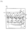
- FIG. 1 is a schematic sectional view of an image forming apparatus.
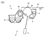
- FIG. 2 is a schematic sectional view of the image forming unit.
- FIG. 3 is a schematic sectional view of the developing device.
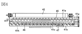
- FIG. 4 is a schematic top view of the developing device.
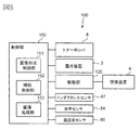
- FIG. 5 is a block diagram showing a control mode of the main part of the image forming apparatus.
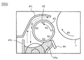
- FIG. 6 is a schematic cross-sectional view for explaining the air flow inside the developing container.
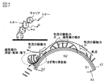
- FIG. 7 is a schematic diagram showing the movement of the developer and the airflow around the developing sleeve.
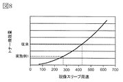
- FIG. 8 is a graph showing the relationship between the peripheral speed of the developing sleeve and the toner scattering amount.
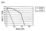
- FIG. 9 is a graph for explaining the stopping operation of the developing device in the first embodiment.
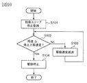
- FIG. 10 is a flowchart of the stopping operation of the developing device in the first embodiment.
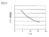
- FIG. 11 is a graph showing the relationship between the toner concentration of the developer and the toner scattering amount.
- FIG. 12 is a graph showing the relationship between the peripheral speed of the developing sleeve and the toner charge amount for each toner concentration of the developer.
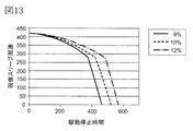
- FIG. 13 is a graph for explaining the stopping operation of the developing device according to the second embodiment.
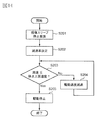
- FIG. 14 is a flowchart of the stopping operation of the developing device according to the second embodiment.
- FIG. 15 is a graph showing the relationship between the peripheral speed of the developing sleeve and the toner scattering amount for each relative humidity.
- FIG. 16 is a graph for explaining the stopping operation of the developing device according to the third embodiment.
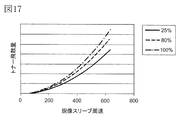
- FIG. 17 is a graph showing the relationship between the peripheral speed of the developing sleeve and the toner scattering amount for each printing rate.
- FIG. 18 is a graph for explaining the stopping operation of the developing device according to the fourth embodiment.
- 19A and 19B are graphs for explaining another example of the stopping operation of the developing device.
- FIG. 1 is a schematic cross-sectional view of an image forming apparatus 100 of the present embodiment.
- the image forming apparatus 100 according to the present exemplary embodiment is a tandem type laser beam printer that employs an intermediate transfer method that can form a full-color image using an electrophotographic method.
- the image forming apparatus 100 includes first, second, third, and fourth image forming units PY, PM, and yellow that respectively form yellow (Y), magenta (M), cyan (C), and black (K) images.
- PC, PK For the elements having the same or corresponding functions or configurations provided in each image forming unit PY, PM, PC, PK, Y, M, C, In some cases, K may be omitted for general explanation.
- FIG. 2 is a schematic cross-sectional view of the image forming unit P.
- the image forming unit P includes a photosensitive drum 1, a charging roller 2, an exposure device 3, a developing device 4, a primary transfer roller 52, and a drum cleaning device 6 which will be described later.
- a photosensitive drum 1 that is a rotatable drum-type photosensitive member (electrophotographic photosensitive member) as an image carrier that carries a toner image is driven to rotate in the direction of arrow R1 (clockwise) in the drawing.
- the surface of the rotating photosensitive drum 1 is uniformly charged to a predetermined potential having a predetermined polarity (negative polarity in this embodiment) by a charging roller 2 as a charging unit.
- a predetermined charging voltage charging bias
- the charged surface of the photosensitive drum 1 is scanned and exposed in accordance with image information by an exposure device (laser scanner) 3 as an exposure unit, and an electrostatic latent image (electrostatic image) is formed on the photosensitive drum 1.
- the exposure apparatus 3 is configured as one unit capable of exposing each photosensitive drum 1 of each image forming unit S.
- the electrostatic latent image formed on the photosensitive drum 1 is developed (visualized) by a developing device 4 as a developing unit, and a toner image is formed on the photosensitive drum 1.
- the same polarity as the charging polarity of the photosensitive drum 1 (negative polarity in this embodiment) is applied to the exposed portion on the photosensitive drum 1 where the absolute value of the potential has been lowered by being exposed after being uniformly charged. ) Is charged with charged toner (reverse development).
- the developing device 4 will be described in detail later.
- a transfer device 5 is arranged above each photosensitive drum 1 in the drawing.
- the transfer device 5 includes an intermediate transfer belt 51 configured by an endless belt as an intermediate transfer member, which is disposed so as to face each photosensitive drum 1 of each image forming unit S.
- the intermediate transfer belt 51 is stretched around a plurality of stretching rollers and stretched with a predetermined tension.
- the intermediate transfer belt 51 rotates (circulates) in the direction of the arrow R2 in the figure when a driving roller that is one of a plurality of stretching rollers is rotationally driven.
- a primary transfer roller 52 as a primary transfer unit is disposed at a position facing each photosensitive drum 1 on the inner peripheral surface side of the intermediate transfer belt 51.
- the primary transfer roller 52 is pressed toward the photosensitive drum 1 through the intermediate transfer belt 51 to form a primary transfer portion N1 where the photosensitive drum 1 and the intermediate transfer belt 51 are in contact with each other.
- a secondary transfer roller 53 as a secondary transfer unit is disposed on the outer peripheral surface side of the intermediate transfer belt 51 at a position facing a secondary transfer counter roller which is one of a plurality of stretching rollers. .
- the secondary transfer roller 53 is pressed toward the secondary transfer counter roller via the intermediate transfer belt 51 to form a secondary transfer portion N2 where the intermediate transfer belt 51 and the secondary transfer roller 53 are in contact with each other.
- the toner image formed on the photosensitive drum 1 as described above is transferred (primary transfer) onto the rotating intermediate transfer belt 51 in the primary transfer portion N1.
- the primary transfer roller 52 is supplied from a primary transfer power source (not shown) with a DC voltage having a polarity (positive in this embodiment) opposite to the toner charging polarity (normal charging polarity) at the time of development.
- a certain primary transfer voltage (primary transfer bias) is applied.
- yellow, magenta, cyan, and black toner images formed on each photosensitive drum 1 are sequentially transferred so as to be superimposed on the intermediate transfer belt 51.
- the toner image formed on the intermediate transfer belt 51 is a recording material such as paper (recording medium, transfer material, and the like) that is nipped and conveyed between the intermediate transfer belt 51 and the secondary transfer roller 53 in the secondary transfer portion N2.
- a sheet (S) is transferred (secondary transfer).
- a secondary transfer roller 53 receives a secondary transfer from a secondary transfer power source (not shown) having a DC voltage having a polarity opposite to the normal charging polarity of the toner (positive in this embodiment). A voltage is applied.
- the recording material S is accommodated in a cassette 9 as a recording material accommodation portion.
- the recording material S accommodated in the cassette 9 is conveyed to the registration roller 11 by a feeding / conveying unit 10 provided with a pickup roller, a conveyance roller, and the like. Then, the recording material S is supplied to the secondary transfer portion N2 by the registration roller 11 in timing with the toner image on the intermediate transfer belt 51.
- the recording material S to which the toner image has been transferred is conveyed to a fixing device 12 as a fixing unit, and is heated and pressed by the fixing device 12 so that the toner image is fixed (melted and fixed). It is discharged to the outside of 100 apparatus main bodies 110.
- the toner (primary transfer residual toner) remaining on the surface of the photosensitive drum 1 after the primary transfer is removed from the surface of the photosensitive drum 1 and collected by a drum cleaning device 6 as a photosensitive member cleaning means. Further, the toner (secondary transfer residual toner) remaining on the surface of the intermediate transfer belt 51 after the secondary transfer is removed from the surface of the intermediate transfer belt 51 and collected by the belt cleaning device 7 as an intermediate transfer body cleaning unit. . 2. Development device
- FIG. 3 is a schematic cross-sectional view of the developing device 4 as viewed in the direction of the rotation axis of the photosensitive drum 1.
- FIG. 4 is a schematic top view of the developing device 4 in a state where an upper lid 41i described later is opened.
- the developing device 4 in this embodiment uses a two-component developer including non-magnetic toner particles (toner) and magnetic carrier particles (carrier) as a developer.
- the developing device 4 includes a developing container 41 that stores a developer.
- the developing container 41 is provided with an opening 41 d at a portion facing the photosensitive drum 1.
- a hollow cylindrical developing sleeve 42 as a developer carrying member is rotatably provided in the developing container 41 so that a part of the opening 41d is exposed to the outside.
- the developing sleeve 42 is made of a nonmagnetic material.
- the developing sleeve 42 is rotationally driven in the direction indicated by an arrow R3 (counterclockwise) in the drawing by a driving unit 120 (FIG. 5) as driving means.
- the developing sleeve 42 is rotationally driven in a direction in which the photosensitive drum 1 and the developing sleeve 42 move in the forward direction at a portion (developing region) between the photosensitive drum 1 and the developing sleeve 42.
- the drive unit 120 includes a DC motor as a drive source and a drive transmission member such as a gear.
- a magnet roll (magnet) 43 is disposed as a magnetic field generating means.
- the magnet roll 43 is fixed to the developing container 41 so as not to rotate.
- the magnet roll 43 has a plurality of magnetic poles along the circumferential direction.
- the amount (layer thickness) of the developer carried on the surface of the developing sleeve 42 is regulated at one edge of the opening 41d of the developing container 41 (the upstream edge in the rotation direction of the developing sleeve 42).
- a developing blade 44 as a regulating member is provided.
- the inside of the developing container 41 is divided into a developing chamber 41a and a stirring chamber 41b by a partition wall 41c extending in a substantially vertical direction. Delivery portions 41f and 41g that allow the developer to pass between the developing chamber 41a and the stirring chamber 41b are provided at both ends in the longitudinal direction of the partition wall 41c (left and right sides in FIG. 4).
- the developing chamber 41a, the stirring chamber 41b, and the transfer portions 41f and 41g constitute a developer transport path.
- the upper part of the container main body 41e that forms the developing chamber 41a and the stirring chamber 41b is closed by an upper lid 41i, and an opening 41d that faces the photosensitive drum 1 is formed by the container main body 41e and the upper lid 41i.
- a first screw 45 as a conveying member is disposed inside the developing chamber 41a, and a second screw 46 as a conveying member is disposed inside the stirring chamber 41b.
- the first and second screws 45 and 46 are screw members each provided with a spiral blade as a transport unit around the axis (rotation axis) of the magnetic body.
- the first and second screws 45 and 46 are driven in conjunction with the developing sleeve 42 by distributing the driving force from the driving unit 120 that drives the developing sleeve 42.
- the first screw 45 agitates and conveys the developer in the developing chamber 41a.
- the second screw 46 agitates and conveys the toner supplied into the agitating chamber 41b via the replenishing port 41h and the developer in the agitating chamber 41b, so that the toner concentration of the developer is uniform.
- the first and second screws 45 and 46 rotate around a rotation axis substantially parallel to the rotation axis direction (development width direction) of the developing sleeve 42.
- the first and second screws 45 and 46 convey the developer in opposite directions along the rotational axis direction of the developing sleeve 42. As a result, the developer is circulated through the inside of the developing container 41 via the transfer portions 41f and 41g.
- the developer in the developing chamber 41a in which the toner is consumed in the developing process and the toner concentration is lowered moves into the stirring chamber 41b through one connecting portion 41f (left side in FIG. 4).
- a toner hopper 8 (FIG. 1) as a replenishing device is connected to a replenishing port 41h provided in the vicinity of the most upstream part of the stirring chamber 41b.
- the toner discharge port (not shown) of the toner hopper 8 is provided with a replenishing screw (not shown) for transporting the toner. Then, an amount of toner commensurate with the amount consumed by the development is supplied from the toner hopper 8 to the stirring chamber 41b through the supply port 41h.
- the developer in the stirring chamber 41b that has been stirred and mixed with the replenished toner moves to the developing chamber 41a via the other connecting portion 41g (right side in FIG. 4). Then, the developer that has moved to the developing chamber 41 a is supplied to the developing sleeve 42.
- the developer container 41 has an inductance for detecting the magnetic permeability of the developer in the stirring chamber 41b as a developer concentration detecting means for detecting the toner concentration T / D of the developer (ratio of the toner weight to the developer weight).
- a sensor 47 is provided.
- the inductance sensor 47 generally detects T / D as follows. An induced current is generated in the coil in accordance with the amount of magnetic material contained in the space in the detection region. The amount of current changes depending on the ratio of the toner, the carrier, and the gap in the detection area. Then, T / D can be detected based on the potential difference between the potential due to the current and the reference voltage applied to the other coil.
- toner replenishment operation control toner replenishment control for the developing device 4 will be described in the second embodiment, which is more relevant.
- the toner supply control employed in this embodiment is the same as that described in the second embodiment.
- the developer is charged negatively and the carrier is positively charged by friction in the process of being conveyed while being stirred.
- the developer that has moved to the developing chamber 41a is in a state where the toner adheres to the surface of the carrier.
- the developer is attracted to the surface of the developing sleeve 42 by the magnetic field generated by the pumping magnetic pole S ⁇ b> 3 of the magnet roll 43 and is carried on the developing sleeve 42.
- a developer pool is formed in the vicinity of the pumping magnetic pole S3 on the developing sleeve.
- the developer on the developing sleeve 42 is conveyed by the rotation of the developing sleeve 42, and forms a magnetic spike that is raised by the magnetic field generated by the cut magnetic pole N ⁇ b> 1 of the magnet roll 43.
- the developer magnetic head is regulated by the developing blade 44 arranged to face the cut magnetic pole N1 so that the magnetic spike of the developer has a predetermined length.
- a predetermined amount of developer is conveyed to the developing area where the photosensitive drum 1 and the developing sleeve 42 face each other.
- the developer on the developing sleeve 42 forms magnetic spikes that are spiked by the magnetic field generated by the developing magnetic pole S 1 of the magnet roll 43.
- the magnetic spike on the developing sleeve 42 contacts the photosensitive drum 1 in the developing region. Then, toner is supplied to the photosensitive drum 1 from the magnetic spikes of the developer, whereby the electrostatic image on the photosensitive drum 1 is developed as a toner image. At this time, a developing voltage (developing bias) in which a DC voltage and an AC voltage are superimposed is applied to the developing sleeve 42 from a developing power source (not shown). This improves the development efficiency, that is, the rate of toner application to the electrostatic latent image.
- the developer on the developing sleeve 42 after supplying the toner to the photosensitive drum 1 is conveyed by the magnetic field generated by the conveying magnetic pole N2 of the magnet roll 43 and the rotation of the developing sleeve 42.
- the developer is peeled off from the surface of the developing sleeve 42 by the repulsive magnetic field formed by the peeling magnetic pole S2 and the pumping magnetic pole S3 of the magnet roll 43 having the same polarity, and returns to the developing chamber 41a. . 3. Control mode
- FIG. 5 is a block diagram illustrating a control mode of a main part of the image forming apparatus 100.
- the operation of each unit of the image forming apparatus 100 is controlled by a control unit 150 provided in the apparatus main body 110.
- the control unit 150 includes a CPU as an arithmetic control unit and a ROM or RAM as a storage unit.
- the control unit 150 controls the image forming apparatus 100 using the RAM as a work area according to a program stored in the ROM.
- the apparatus main body 110 is connected to a host device such as an image reading device (reader) or a personal computer (not shown) so as to communicate with each other.
- a host device such as an image reading device (reader) or a personal computer (not shown) so as to communicate with each other.
- the control unit 150 processes image information from these devices by the image processing unit 153 to generate a drive signal for each unit, and the image forming unit 151 controls the operation of each unit. In addition, the control unit 150 performs toner replenishment control on the developing device 4 by the replenishment control unit 152.
- the optical sensor 54 and the temperature / humidity sensor 60 in FIG. 5 will be described in the second and subsequent embodiments. 4). Toner scattering
- FIG. 6 is a schematic cross-sectional view for explaining the air flow inside the developing container 41.
- FIG. 7 is a schematic diagram for explaining the movement of the developer and the airflow around the developing sleeve 42.
- the toner When the magnetic spike is raised by the transport magnetic pole N2, the toner may be released from the carrier by centrifugal force. Further, when the magnetic spike rising by the peeling magnetic pole S2 collides with the developer reservoir formed by the pumping magnetic pole S3 immediately before being peeled off from the developing sleeve 42, the toner is released from the carrier by the impact due to the collision. There are things to do. Further, when the developer peeled off from the developing sleeve 42 collides with the developer surface in the developing chamber 41a, the toner may be released from the carrier due to the impact caused by the collision. Further, the toner replenished to the developing container 41 may fly up into the air due to the impact of the rotation of the second screw 46 before being mixed with the developer in the developing container 41.
- the toner may scatter from the developer immediately after passing through the SB gap, which is the gap between the developing blade 44 and the developing sleeve 42.
- the SD gap which is the gap between the photosensitive drum 1 and the developing sleeve 42, when the toner is released from the carrier due to the action of the electric field, the toner that could not be recovered due to the action of the electric field may be scattered. is there.
- the amount of toner scattered through the gap between the developing sleeve 42 and the upper lid 41i tends to increase. That is, the toner scattered inside the developing container 41 is likely to be scattered on the airflow flowing from the inside of the developing container 41 to the outside along the surface of the upper cover 41 i in the gap between the developing sleeve 42 and the upper cover 41 i.
- toner scattering can be suppressed by attaching a seal member such as a urethane sheet to the developing blade 44.
- the toner scattering amount is relatively small.
- the toner scattering due to the above-described various factors, particularly the toner scattering through the gap between the developing sleeve 42 and the upper lid 41i, is a steady air flow while the developing device 4 is being driven (the developing sleeve 42 is rotating in a steady state). Occurs when the is formed.
- Such toner scattering during driving of the developing device 4 can be countered by, for example, the configurations described in Patent Documents 1 and 2 described above.
- the path of the airflow flowing from the outside to the inside of the developing container 41 in the air flow while the developing device 4 is driven becomes the path of the airflow that flows out from the inside of the developing container 41 to the outside when the developing apparatus 4 is stopped. Therefore, the air containing the toner inside the developing container 41 flows out to the outside of the developing container 41 at a stretch. As a result, irregular toner scattering from the developing device 4 occurs when the developing device 4 is stopped. 5). Toner scattering control
- the amount of toner released from the carrier in a steady state while the developing device 4 is driven is greatly influenced by the centrifugal force according to the rotation speed of the developing sleeve 42, except for fluctuation factors due to physical properties such as the toner charge amount. For this reason, the liberation amount varies greatly depending on the square of the angular velocity of the developing sleeve 42, that is, the rotational speed of the developing sleeve 42. Also, some of the kinetic energy lost due to the collision between the developers by the stripping magnetic pole S2 and part of the kinetic energy lost when the developer peeled off from the developing sleeve 42 collides with the developer surface in the developing chamber 41a. , Acting as a force to release the toner from the carrier.
- the air flow generated by the rotation of the developing sleeve 42 also increases in proportion to the rotation speed of the developing sleeve 42. Therefore, the faster the developing sleeve 42 rotates, the easier the toner released from the carrier rides on the airflow and flows out of the developing container 41.
- the rotation speed of the developing sleeve 42 is represented by “peripheral speed”.
- FIG. 8 shows the relationship between the peripheral speed of the developing sleeve 42 and the toner scattering amount.
- the paper is placed in the vicinity of the gap between the developing sleeve 42 and the upper lid 41i, the developing device 4 is idled for a predetermined time, and the amount of toner adhering to the paper is measured as an integral value of the adhering area and density to determine the toner. The amount of scattering was used.
- FIG. 9 shows the relationship between the time from when the developing sleeve 42 rotates in a steady state until it stops (herein also referred to as “driving stop time”) and the peripheral speed of the developing sleeve 42.
- the peripheral speed of the developing sleeve 42 is 420 [mm / sec] in a steady state during driving of the developing device 4 (FIG. 8). Then, when the drive by the drive unit 120 is simply stopped (the DC motor is turned off) from the state in which the development sleeve 42 is rotationally driven by the drive unit 120 at the steady peripheral speed, the development sleeve is taken in about 200 msec. The rotation of 42 stops (broken line in FIG. 9). If the rotation of the developing sleeve 42 is suddenly stopped in this way, toner scattering occurs at a level that causes a problem for the reasons described above.
- the control unit 150 changes the developing sleeve 42 from being driven and rotated by the driving unit 120 to being stopped without being driven by the driving unit 120 (during the stop operation). ), The following control is performed. That is, the control unit 150 stops the driving of the developing sleeve 42 by the driving unit 120 after reducing the driving speed of the developing sleeve 42 by the driving unit 120.
- the driving speed of the developing sleeve 42 by the driving unit 120 is set so that the peripheral speed of the developing sleeve 42 is a peripheral speed that can sufficiently suppress the blowing of air containing toner from the developing container 4. Until it slows down at a low deceleration rate. Then, after the peripheral speed of the developing sleeve 42 reaches a peripheral speed at which toner scattering can be suppressed, the driving of the developing sleeve 42 by the driving unit 120 is stopped (the DC motor is turned off).
- the peripheral speed of the developing sleeve 42 is decelerated at a deceleration rate higher than the deceleration rate until then, but since the toner has been decelerated so far, toner scattering can be sufficiently suppressed. .
- irregular toner scattering during the stop operation of the developing device 4 depends on the peripheral speed of the developing sleeve 42. Therefore, when the developing device 4 is stopped, it is desired to slowly stop the rotation of the developing sleeve 42 in a state where the airflow is stabilized. However, it is not preferable to extend the drive stop time more than necessary in consideration of stress on the developing sleeve 42 and the developer.
- the peripheral speed of the developing sleeve 42 is once decelerated at a low deceleration rate to a predetermined peripheral speed that can suppress irregular toner scattering. Then, after the airflow is stabilized by decelerating to a predetermined peripheral speed, the driving of the developing sleeve 42 is stopped. Thereby, irregular toner scattering during the stop operation of the developing device 4 can be suppressed. This will be described in more detail below.
- the developing sleeve 42 is slowly decelerated from a state where the developing sleeve 42 is rotating at a high speed to a predetermined peripheral speed at which the toner scattering amount is sufficiently reduced. It is desirable to stop completely.
- the amount of toner scattering changes with the power of the peripheral speed of the developing sleeve 42 (about the square in the configuration of this embodiment). Therefore, in order to reduce the toner scattering amount, it is desired to suppress a rapid speed change on the high speed side of the developing sleeve 42. For this reason, in this embodiment, when the developing device 4 is stopped, the fluctuation in the peripheral speed of the developing sleeve 42 immediately after the stop request is reduced.
- the peripheral speed of the developing sleeve 42 having a diameter of 20 [mm] is the first rotational speed. 420 [mm / sec].
- the peripheral speed of the photosensitive drum 1 having a diameter of 30 [mm] is 240 [mm / sec].
- the developer has a toner concentration T / D of 12%.
- the threshold of the peripheral speed of the developing sleeve 42 (also referred to as “stop upper limit speed” here) that can sufficiently suppress the toner scattering is the second rotation.
- the speed is 280 [mm / sec].
- the circumferential speed of the photosensitive drum is 160 [mm / sec]. That is, the amount of scattered toner can be sufficiently reduced by stopping the driving of the developing sleeve 42 by the driving unit 120 from the state where the peripheral speed of the developing sleeve 42 is equal to or lower than the upper limit stop speed as a predetermined peripheral speed.
- the stop upper limit speed is not limited to the value in this embodiment, and can be set as appropriate so that toner scattering can be sufficiently suppressed.
- the deceleration rate of the peripheral speed of the developing sleeve 42 means a decrease amount of the peripheral speed of the developing sleeve 42 with respect to time (negative acceleration). Since the deceleration rate is acceleration, it is represented by a coefficient that is multiplied by the square value of time. That is, the speed difference is divided by the time. However, the present invention is not limited to this, and an exponential coefficient, a logarithmic coefficient, or the like may be used.
- the driving speed of the developing sleeve 42 by the driving unit 120 is the developing sleeve in a state where the driving unit 120 transmits driving force to the developing sleeve 42 (a state in which the developing sleeve 42 is rotated at a certain rotational speed). Means a rotational speed of 42. This drive speed typically corresponds to the rotational speed of the drive shaft of the drive source in the state where the drive force is transmitted.
- FIG. 10 is a flowchart showing the flow of the stopping operation of the developing device 4.
- the control unit 150 determines whether the peripheral speed of the developing sleeve 42 is larger than the upper limit stop speed (S102).
- a job is a series of operations for forming and outputting an image on one or a plurality of recording materials S according to one start instruction.
- the control unit 150 is configured so that the developing sleeve 42 is driven by the driving unit 120 at the first deceleration rate set in advance as described above (the deceleration rate is increased as the speed is lower) until the peripheral speed of the developing sleeve 42 reaches the upper limit speed.
- the peripheral speed of the developing sleeve 42 can be obtained from a detection result by a rotation speed detection unit that detects the rotation speed of the DC motor of the drive unit 120, for example.
- a rotation speed detection unit that detects the rotation speed of the DC motor of the drive unit 120
- any available mechanism a mechanism for detecting the rotational speed of the drive shaft with an encoder, a mechanism for electrically detecting the rotational speed, etc.
- the peripheral speed of the developing sleeve 42 at each timing in the operation sequence of the image forming apparatus 100 can be obtained in advance. Therefore, the stop operation according to the present embodiment can be performed by performing the stop operation of the developing device 4 according to a preset stop pattern.
- the control unit 150 reduces the driving speed of the developing sleeve 42 by the driving unit 120 until the peripheral speed of the developing sleeve 42 reaches a predetermined peripheral speed during the stop operation. Is decelerated at the first deceleration rate. Then, the control unit 150 stops the driving of the developing sleeve 42 by the driving unit 120 after the peripheral speed of the developing sleeve 42 reaches a predetermined peripheral speed, so that the peripheral speed of the developing sleeve 42 is made higher than the first reduction rate. Decelerate and stop at a high second deceleration rate.
- the first deceleration rate is set such that the deceleration rate increases as the peripheral speed of the developing sleeve 42 decreases.
- first deceleration rate (first rotation speed ⁇ second rotation speed) / time required for deceleration
- second deceleration rate second rotation speed / second rotation speed to stop. It is calculated in the time required.
- the motor is turned off after reaching the stop upper limit speed.
- a target may be set to a new rotation speed smaller than the stop upper limit speed, and the motor may be turned off after reaching the new rotation speed.
- a configuration in which the image forming apparatus has a plurality of image forming speeds and a plurality of rotation speeds of the developing sleeves 42 in association therewith will be described.
- the above stop control is executed.
- the control unit 150 does not perform the above control and turns off the rotation of the developing sleeve 42 after the end of the developing process. Control.
- the stop upper limit speed may be selected and set from the rotation speeds of the plurality of developing sleeves 42. 6).
- the toner scattering amount from the developing device 4 during the stop operation of the developing device 4 was compared between the configuration of this example and the conventional configuration.
- the conventional configuration is substantially the same as the configuration of the present embodiment except that the operation of reducing the drive speed of the developing sleeve 42 by the drive unit 120 is not performed when the developing device 4 is stopped.
- the toner adheres to the upper lid 41i of the developing device 4 and the flange of the developing sleeve 42 at a level where there is a concern that the toner adheres to the charging device 2 and the exposure device 3 when an image is formed over a long period of time.
- toner adhesion at a problematic level was not observed.
- the toner density T / D of the developer in the developing device 4 is detected, and the stop pattern of the developing sleeve 42 during the stop operation of the developing device 4 is optimized according to the detected T / D.
- the stop pattern of the developing sleeve 42 at least one of the stop upper limit speed or the deceleration rate up to the stop upper limit speed can be optimized. In this embodiment, the deceleration rate up to the stop upper limit speed is optimized.
- the release of toner from the carrier is caused by factors such as impact and centrifugal force.
- This adhesion force includes electrostatic adhesion force such as Coulomb force and non-electrostatic adhesion force such as liquid cross-linking force, but electrostatic adhesion force is dominant.
- the charge amounts of the toner and the carrier are determined by the probability of contact of the toner with the carrier, and the charge amount increases as T / D decreases.
- FIG. 11 shows the relationship between T / D and the charge amount of toner. As shown in the figure, the charge amount of the toner is almost inversely proportional to T / D.
- FIG. 12 shows the relationship between the peripheral speed of the developing sleeve 42 and the toner scattering amount when T / D is 8%, 10%, and 12%, respectively. From the figure, it can be seen that the higher the T / D, the easier the toner scattering occurs. Therefore, it is desirable to decrease the deceleration rate up to the stop upper limit speed as T / D increases.
- the toner replenishment control for the developing device 4 will be described.
- the image forming apparatus 100 performs automatic toner replenishment (ATR) that replenishes the developing device 4 with an amount of toner corresponding to the amount consumed by development.
- ATR automatic toner replenishment
- the control unit 150 controls the number of rotations of the replenishing screw of the toner hopper 8 according to the printing rate (image area ratio) at the time of image formation, the detection result of the inductance sensor 47, and the detection result of the image density of the patch image. 41 is replenished with toner. That is, the toner replenishment amount corresponding to the toner consumption amount predicted from the printing rate at the time of image formation is obtained.
- the toner supply amount based on the printing rate is corrected. Further, the target value of the detection result of the inductance sensor 47 is corrected using the density detection result of the patch image formed at a predetermined frequency.
- an arbitrary replenishment amount is not replenished at any time, but the replenishment amount is reduced to a preset replenishment amount (one rotation of the replenishment screw of the toner hopper 8 in this embodiment). The supply screw is rotated once for each supply amount. Thereby, a stable replenishment amount can be obtained.
- the image processing unit 153 of the control unit 150 calculates a toner consumption amount due to image formation based on image information received from an image reading device or a personal computer connected via a network or the like.
- the toner consumption is obtained from the printing rate based on the video count value (image signal value) integrated based on the image information, and integrated for each image output.
- the replenishment control unit 152 of the control unit 150 obtains the toner amount corresponding to the toner consumption amount as the toner replenishment amount, but the T / D detected by the inductance sensor 47 is deviated from the T / D target value.
- the toner replenishment amount is corrected so as to reduce the deviation.
- the replenishment control unit 152 rotates the replenishment screw by the necessary number of rotations to replenish toner to the developing device 4. To do.
- the replenishment control unit 152 forms a patch image of a predetermined size (for example, 15 mm square) with a predetermined latent image contrast on the photosensitive drum 1 at a predetermined frequency (for example, for each predetermined number of image outputs), and this is transferred to the intermediate transfer. Transfer to the belt 51. Then, the image density (reflection density) of the patch image is measured on the intermediate transfer belt 51 by an optical sensor 54 (FIGS. 1 and 5) as image density detection means. Then, the measured image density is compared with the reference image density, and the target value of T / D is changed so as to reduce the deviation of the image density (patch detection control).
- the toner charge amount can be predicted from the toner amount used for forming the patch image, and the variation in the image density caused by the change in the toner charge amount due to the deterioration of the carrier can be dealt with.
- the control unit 150 changes the deceleration rate up to the stop upper limit speed according to the T / D detection result by the inductance sensor 47.
- the control unit 150 performs control so that the deceleration rate up to the stop upper limit speed is decreased stepwise as T / D increases.
- the control unit 150 performs the process up to the stop upper limit speed according to the average value of the T / D detection results by the inductance sensor 47 from the patch detection control immediately before the job ends to immediately before the job. Change the deceleration rate. That is, in this embodiment, the average value of the detection results of T / D when the driving of the developing device 4 is stopped in a state where the target value of T / D is set to the latest.
- T / D detection result after the patch detection control is ignored. Note that the detection result of T / D at an arbitrary timing can be used as long as it can be used as an index of the ease of toner scattering during the stop operation of the developing device 4.
- FIG. 13 shows the relationship between the driving stop time and the peripheral speed of the developing sleeve 42 from the state in which the developing sleeve 42 rotates in a steady state to the stop in the present embodiment.
- T / D is 8% or more and less than 10% (solid line in FIG. 13), 10% or more and less than 12% (broken line in FIG. 13), 12% or more (dashed line in FIG. 13).
- the deceleration rate to the stop upper limit speed is lowered stepwise.
- the attenuation rate up to the stop upper limit speed in each case is set such that the deceleration rate increases as the peripheral speed decreases until the stop upper limit speed is reached.
- FIG. 14 is a flowchart showing the flow of the stopping operation of the developing device 4 in this embodiment.
- the control unit 150 determines a deceleration rate up to the stop upper limit speed based on the detection result of T / D (S202). Thereafter, the control unit 150 determines whether or not the peripheral speed of the developing sleeve 42 is greater than the stop upper limit speed (S203).
- the control unit 150 sets the driving speed of the developing sleeve 42 by the driving unit 120 at the deceleration rate determined as described above (the deceleration rate is increased as the speed decreases) until the peripheral speed of the developing sleeve 42 reaches the stop upper limit speed.
- the image forming apparatus 100 includes the inductance sensor 47 that detects the toner concentration as a concentration detection unit that detects the concentration of the developer contained in the developing container 41.
- the control unit 150 changes the deceleration rate (first deceleration rate) up to the stop upper limit speed according to the detection result of the inductance sensor 47.
- the control unit 150 uses the first deceleration rate when the toner density is a second density higher than the first density than when the toner density is the first density. Lower the direction.
- T / D was varied as 8%, 10%, and 12%, and the same test for checking the level of toner scattering as in Example 1 was performed.
- T / D is 8% which is relatively low, even if the deceleration rate to the stop upper limit speed is relatively high, adhesion of toner to the periphery of the developing device 4 at the level at which the problem occurs is observed. I could't.
- T / D is relatively high of 12%, adhesion of toner to the periphery of the developing device 4 at a problematic level can be seen by making the deceleration rate to the stop upper limit speed relatively low. There wasn't.
- the amount of toner adhering to the periphery of the developing device 4 was substantially the same.
- the toner scattering can be sufficiently suppressed even in a situation where the toner scattering from the developing device 4 is likely to occur during the stop operation of the developing device 4. Further, according to the present embodiment, in a situation where the toner scattering from the developing device 4 is difficult to occur during the stopping operation of the developing device 4, the toner is suppressed while suppressing an increase in the driving stop time of the developing sleeve 42 more than necessary. Scattering can be suppressed.
- the driving speed of the developing sleeve 42 by the driving unit 120 is reduced when T / D is less than a predetermined value (for example, 8%). The operation may not be performed.
- the T / D range (step size) for changing the deceleration rate is not limited to the range of the present embodiment, and can be set as appropriate so that toner scattering can be sufficiently suppressed.
- the concentration detection means for detecting the concentration of the developer stored in the developing container 41 is not limited to the inductance sensor, and any appropriate means can be used.
- the developer concentration indirectly obtained from information such as toner consumption amount and toner supply amount based on image information may be used.
- the environment of the developer atmosphere is detected (measured or predicted), and the stop pattern of the developing sleeve 42 during the stop operation of the developing device 4 is optimized according to the detected environment.
- the environment is typically at least one of temperature and relative humidity in at least one of the inside and the outside of the developing device 4.
- the relative humidity is obtained by detecting the temperature and humidity inside the developing device 4, and the stop pattern of the developing sleeve 42 is optimized according to the relative humidity.
- the stop pattern of the developing sleeve 42 the deceleration rate up to the stop upper limit speed is optimized as in the second embodiment.
- FIG. 15 shows the relationship between the peripheral speed of the developing sleeve 42 and the toner scattering amount when the relative humidity inside the developing device 4 is 5%, 50%, and 80%, respectively. From the figure, it can be seen that toner scattering is more likely to occur as the relative humidity inside the developing device 4 increases. Therefore, it is desirable to decrease the deceleration rate up to the stop upper limit speed as the relative humidity inside the developing device 4 is higher.
- the developing device 4 is provided with a temperature / humidity sensor 60 (FIG. 5) for detecting the temperature and humidity inside the developing device 4 as environment detecting means.
- the control unit 150 obtains the relative humidity of the developer atmosphere in the developing device 4 based on the temperature and humidity detection results input from the temperature and humidity sensor 60.
- the control unit 150 when the obtained relative humidity is 45% or more, changes the deceleration rate up to the stop upper limit speed according to the value of the relative humidity. In the present embodiment, the control unit 150 performs control so that the deceleration rate up to the stop upper limit speed is decreased stepwise as the relative humidity increases. On the other hand, in this embodiment, when the obtained relative humidity is less than 45%, the control unit 150 does not perform an operation of reducing the driving speed of the developing sleeve 42 by the driving unit 120 when the developing device 4 is stopped.
- FIG. 16 shows the relationship between the drive stop time and the peripheral speed of the developing sleeve 42 from the state in which the developing sleeve 42 rotates in a steady state to the stop in the present embodiment.
- the relative humidity inside the image forming apparatus 100 is controlled to be between 5% and 80%.
- the relative humidity is less than 45% (solid line in FIG. 16)
- the driving of the developing sleeve 42 is simply stopped (the DC motor is turned off) when the developing device 4 is stopped.
- the relative humidity is 45% or more and 80% or less
- the deceleration rate up to the stop upper limit speed is decreased stepwise as the relative humidity increases for each predetermined increment (see FIG. 16).
- the attenuation rate up to the stop upper limit speed is set such that the deceleration rate increases as the peripheral speed decreases until the stop upper limit speed is reached.
- control unit 150 decelerates the deceleration rate up to the stop upper limit speed (or the driving speed of the developing sleeve 42 by the driving unit 120) based on the detection result of the relative humidity of the developer atmosphere. Decide not to take action).
- the image forming apparatus 100 is a temperature / humidity sensor 60 that detects the relative humidity in the developing container 41 as an environment detecting unit that detects the environment of the developer contained in the developing container 41.
- the control unit 150 changes the deceleration rate (first deceleration rate) up to the stop upper limit speed according to the detection result of the temperature / humidity sensor 60.
- the control unit 150 performs the first operation when the environmental humidity is a second humidity higher than the first humidity than the first deceleration rate when the environmental humidity is the first humidity. Decrease the deceleration rate.
- Example 2 the same humidity test as in Example 1 was performed to examine the level of toner scattering while shaking the relative humidity between 5% and 80%.
- the relative humidity is less than 45%, no toner adheres to the periphery of the developing device 4 at a problematic level without performing an operation of reducing the driving speed of the developing sleeve 42. It was.
- the relative humidity is 45% to 80%, the reduction rate up to the stop upper limit speed is increased as the relative humidity increases, so that the toner adheres to the periphery of the developing device 4 at a problematic level. was not seen.
- the amount of toner adhered to the periphery of the developing device 4 was substantially the same.
- the configuration for detecting relative humidity which is the configuration for detecting relative humidity
- the configuration for detecting relative humidity may be used.
- the relative humidity inside the developing device 4 is directly detected
- the temperature and humidity outside the apparatus main body 110 and the temperature of the developing device 4 are detected to detect the relative humidity inside the developing device 4.
- a configuration for calculating (predicting) humidity may be employed.
- the control unit 150 sets the deceleration rate (the first speed to the stop upper limit speed). (Deceleration rate) may be changed as follows. That is, the first deceleration rate when the environmental temperature is the second temperature higher than the first temperature is made lower than the first deceleration rate when the environmental temperature is the first temperature. You can do it.
- the control according to T / D described in the second embodiment and the control according to relative humidity described in the present embodiment may be combined.
- the deceleration rate up to the stop upper limit speed for each T / D within a predetermined range may be set for each of the relative humidity with a predetermined step size.
- the relative humidity is less than a predetermined value (for example, 45%) and T / D is less than the predetermined value (for example, 8%)
- the operation of reducing the driving speed of the developing sleeve 42 by the driving unit 120 is not performed. It can be.
- the relative humidity is equal to or higher than the predetermined value and T / D is equal to or higher than the predetermined value
- an operation of reducing the driving speed of the developing sleeve 42 by the driving unit 120 can be performed.
- the stop pattern of the developing sleeve 42 during the stop operation of the developing device 4 is optimized according to the image information. More specifically, in this embodiment, the index is obtained from the video count value (image signal value) integrated based on the image information as an index of the ease of occurrence of toner scattering inside the developing container 41 due to toner replenishment. Use the print rate.
- the deceleration rate up to the stop upper limit speed is optimized as in the second and third embodiments.
- the toner supplied to the developing container 41 is stirred by the second screw 46 before coming into contact with the carrier.
- the printing rate (image duty) 100%
- the largest amount of toner is supplied to the developing container 41.
- about 0.35 [g] is supplied per image output.
- the replenishment amount may further increase, and a maximum of about 0.50 [g] may be replenished by one replenishment. is there.
- a large amount of toner may be scattered inside the developing container 41.
- FIG. 17 shows the relationship between the peripheral speed of the developing sleeve 42 and the toner scattering amount when the average printing rate in the job immediately before the stopping operation of the developing device 4 is 25%, 80%, and 100%. From the figure, it can be seen that the higher the printing rate, the more likely toner scattering occurs. Therefore, the higher the printing rate, the lower the deceleration rate up to the stop upper limit speed.
- the drive stop time (idling time) of the developing sleeve 42 can be shortened by increasing the deceleration rate up to the stop upper limit speed. desirable.
- the control unit 150 changes the deceleration rate up to the stop upper limit speed according to the printing rate.
- the control unit 150 performs control so that the deceleration rate up to the stop upper limit speed is gradually reduced as the printing rate increases.
- the control unit 150 calculates an average printing rate in the job from the start of driving of the developing device 4 to the start of the driving stop operation, and reaches the stop upper limit speed according to the average printing rate. Change the deceleration rate.
- the average printing rate can be obtained by dividing the integrated value of the printing rate for each image output in the job by the number of image outputs in the job.
- the replenishment amount for one rotation of the replenishment screw of the toner hopper 8 is 0.175 [g]
- the replenishment amount for two rotations of the replenishment screw is one image output with a printing rate of 100%. Necessary. In other words, as a guideline, if the average printing rate is less than 50%, it is 0 to 1 rotation per image output, and if the average printing rate is 50% to 99%, it is 1 image output. When the average printing rate is 100% for 1 to 3 rotations, the replenishment amount is 2 to 3 rotations per image output.
- FIG. 18 shows the relationship between the drive stop time and the peripheral speed of the developing sleeve 42 from the state in which the developing sleeve 42 rotates in a steady state to the stop in the present embodiment.
- the upper limit of stoppage in each case where the printing rate is less than 50% (solid line in FIG. 18), 50% or more and less than 100% (broken line in FIG. 18), and 100% (dashed line in FIG. 18). Decrease the deceleration rate to the speed step by step.
- the deceleration rate up to the stop upper limit speed in each case is set such that the deceleration rate increases as the peripheral speed decreases until the stop upper limit speed is reached.
- control unit 150 determines the deceleration rate up to the stop upper limit speed based on the calculation result of the average printing rate.
- the image forming apparatus 100 includes the image processing unit 153 as a processing unit for obtaining the print rate of the output image.
- the control unit 150 changes the deceleration rate (first deceleration rate) up to the stop upper limit speed according to the printing rate obtained by the image processing unit 153.
- the control unit 150 uses the first printing rate when the printing rate is higher than the first printing rate than the first deceleration rate when the printing rate is the first printing rate. Decrease the deceleration rate.
- Example 2 the same test as in Example 1 was conducted to check the level of toner scattering, with the printing rate being changed to 25%, 80%, and 100%.
- the printing rate is relatively low of 25%, even if the deceleration rate up to the stop upper limit speed is relatively high, toner adheres to the periphery of the developing device 4 at a problematic level. There wasn't.
- the printing rate was 100%, the toner was not attached to the periphery of the developing device 4 at a problem level by making the deceleration rate up to the stop upper limit speed relatively low. Further, the amount of toner adhering to the periphery of the developing device 4 was substantially the same for any printing rate.
- the toner replenishment amount based on the printing rate may increase or decrease depending on the detection result of the inductance sensor 47. Therefore, the deceleration rate up to the stop upper limit speed determined according to the printing rate as described above can be corrected according to the detection result of the inductance sensor 47. For example, when the replenishment amount is increased according to the detection result of the inductance sensor 47, the deceleration rate up to the stop upper limit speed can be lowered according to the increase amount. Conversely, when the replenishment amount is decreased according to the detection result of the inductance sensor 47, the deceleration rate up to the stop upper limit speed can be increased according to the decrease amount. As a result, it is possible to perform control in accordance with the state of toner scattering in the developing container 41.
- the average printing rate of the first half of the job is relatively influenced by the scattering of toner in the developing container 41 during the stop operation of the developing device 4. Very few. Therefore, at the end of the job when a job of a certain length or longer (continuous image formation) is executed, the average print rate for a predetermined period immediately before the end of the job is calculated and stopped based on the average print rate The deceleration rate up to the upper limit speed can be determined. As a result, it is possible to perform control according to the average printing rate in a predetermined period in the second half of the job, which has a relatively large influence on the toner scattering in the developing container 41 during the stop operation of the developing device 4.
- the deceleration rate up to the stop upper limit speed during the stop operation of the developing device is set so that the deceleration rate increases as the peripheral speed of the developing sleeve decreases.
- the drive stop time of the developing sleeve can be shortened as much as possible while effectively suppressing a rapid change in the peripheral speed when the peripheral speed of the developing sleeve where toner scattering is likely to occur is large.
- the present invention is not limited to such an embodiment.
- the deceleration rate up to the stop upper limit speed may be substantially constant.
- the stop upper limit speed may be changed as the developing sleeve stop pattern, for example, as shown by the broken line in FIG. Further, for example, as indicated by a one-dot chain line in FIG. 19B, both the deceleration rate up to the stop upper limit speed and the stop upper limit speed may be changed.
- the relatively unlikely situation is a situation where the developer concentration is relatively low, a temperature or humidity is relatively low, or a printing rate is relatively low. Is the situation.
- the relatively likely situation is a situation where the developer concentration is relatively high, a temperature or humidity is relatively high, or a printing rate is relatively high.
- a developing device capable of suppressing toner scattering from the developing device when the driving of the developing device is stopped even when the developer carrying member rotates at a high speed during image formation. Provided.
Landscapes
- Physics & Mathematics (AREA)
- General Physics & Mathematics (AREA)
- Engineering & Computer Science (AREA)
- Life Sciences & Earth Sciences (AREA)
- Atmospheric Sciences (AREA)
- Biodiversity & Conservation Biology (AREA)
- Ecology (AREA)
- Environmental & Geological Engineering (AREA)
- Environmental Sciences (AREA)
- Microelectronics & Electronic Packaging (AREA)
- Dry Development In Electrophotography (AREA)
- Control Or Security For Electrophotography (AREA)
Abstract
現像装置4の停止動作時に、現像スリーブ42の周速がトナー飛散が十分に少なくなる周速になるまで、駆動部120による現像スリーブ42の駆動速度を減速させ、その後駆動部120による現像スリーブ42の駆動を停止する。
Description
本発明は、電子写真方式や静電記録方式を用いた複写機、プリンタ、ファクシミリ装置などの画像形成装置に関するものである。
従来、電子写真方式などを用いた画像形成装置では、感光体などの像担持体に形成された静電潜像を、現像装置によって現像剤を用いて現像することが行われる。現像装置は、一般に、現像剤を収容する現像容器と、現像容器に設けられた開口部から少なくとも一部が外部に露出するように現像容器に回転可能に設けられた現像剤担持体と、を有する。現像剤としては、非磁性トナー粒子(トナー)と、磁性キャリア粒子(キャリア)と、を備えた二成分現像剤がある。二成分現像剤は、トナーに磁性体を含ませなくても良いため、色味が良好であるなどの理由から広く用いられている。
このような現像装置では、現像容器と現像剤担持体との間隙などの現像容器の内部と外部とが繋がっている箇所を通って、現像容器の内部から外部へと流れる気流が発生することがある。そして、キャリアから遊離したトナーなどが上記気流に乗って現像容器の内部から外部へと飛散する場合がある。
これに対し、現像容器にフィルタを設け、現像容器の内圧を低減する方法が提案されている(特開2014−178347号公報)。また、気流の流入口と排出口とを設けて、現像容器の内部の気流を逃がすことが提案されている(特開2015−72331号公報)。
画像形成装置の高速化に伴い、現像剤担持体は高速で回転している。画像形成終了後に現像剤担持体を停止させる際には、現像剤担持体の摩耗等を小さくしたいために、現像剤担持体を短時間で停止することが望まれている。しかし、高速で回転している現像剤担持体を短時間で停止させると、現像容器の内部の気圧が静定しないうちに現像容器の内部への空気の流入が停止することになる。その結果、現像容器の内部の気圧によってトナーを含んだ空気が現像装置の外部へ排出されてしまうといった問題が生ずる。
それに対して、特開2014−178347号公報に記載の構成は、フィルタを通して比較的長い時間をかけて空気の入れ替えが行われて内圧が緩和されるものであり、発生した気流がフィルタを損失無く短時間で通過することはできない。また、特開2015−72331号公報に記載の構成では、現像剤担持体の回転が停止しているため、排出されようとするトナーを回収することができない。
そのため、現像装置の駆動を停止する際の現像装置からのトナー飛散を抑制することが可能な画像形成装置を提供することが望まれている。
本発明は、トナーとキャリアを有する現像剤を担持し、像担持体に形成された静電潜像を現像する回転可能な現像剤担持体と、前記現像剤担持体を駆動するモータと、現像工程時に第一の回転速度で回転している現像剤担持体を停止させる際に、第一の回転速度よりも小さい第二の回転速度に目標速度を設定して第一回転速度から第二回転速度に減速を行い、第二の回転速度に達した後、前記現像剤担持体の回転を停止するように前記モータを制御可能な制御部と、を有し、前記制御部は、第一の回転速度から第二の回転速度までの第一の減速率が第二の回転速度から停止までの第二の減速率よりも小さくなるように前記モータを制御する。
本発明によれば、画像形成時に現像剤担持体が高速で回転している場合であっても、現像装置の駆動を停止する際の現像装置からのトナー飛散を抑制することが可能となる。
図1は画像形成装置の概略断面図である。
図2は画像形成部の概略断面図である。
図3は現像装置の概略断面図である。
図4は現像装置の概略上面図である。
図5は画像形成装置の要部の制御態様を示すブロック図である。
図6は現像容器の内部の気流を説明するための概略断面図である。
図7は現像スリーブの周りの現像剤の動き及び気流を示す模式図である。
図8は現像スリーブの周速とトナー飛散量との関係を示すグラフ図である。
図9は実施例1における現像装置の停止動作を説明するためのグラフ図である。
図10は実施例1における現像装置の停止動作のフロー図である。
図11は現像剤のトナー濃度とトナー飛散量との関係を示すグラフ図である。
図12は現像剤のトナー濃度ごとの現像スリーブの周速度とトナー帯電量との関係を示すグラフ図である。
図13は実施例2における現像装置の停止動作を説明するためのグラフ図である。
図14は実施例2における現像装置の停止動作のフロー図である。
図15は相対湿度ごとの現像スリーブの周速度とトナー飛散量との関係を示すグラフ図である。
図16は実施例3における現像装置の停止動作を説明するためのグラフ図である。
図17は印字率ごとの現像スリーブの周速とトナー飛散量との関係を示すグラフ図である。
図18は実施例4における現像装置の停止動作を説明するためのグラフ図である。
図19の(a)及び(b)は現像装置の停止動作の他の例を説明するためのグラフ図である。
以下、本発明に係る画像形成装置を図面に則して更に詳しく説明する。
1.画像形成装置の全体的な構成及び動作
図1は、本実施例の画像形成装置100の概略断面図である。本実施例の画像形成装置100は、電子写真方式を用いてフルカラー画像の形成が可能な、中間転写方式を採用したタンデム型のレーザビームプリンタである。
画像形成装置100は、それぞれイエロー(Y)、マゼンタ(M)、シアン(C)、ブラック(K)の画像を形成する第1、第2、第3、第4の画像形成部PY、PM、PC、PKを有する。各画像形成部PY、PM、PC、PKに設けられた同一又は対応する機能あるいは構成を有する要素については、いずれかの色用の要素であることを表す符号の末尾のY、M、C、Kを省略して総括的に説明することがある。図2は、画像形成部Pの概略断面図である。本実施例では、画像形成部Pは、後述する感光ドラム1、帯電ローラ2、露光装置3、現像装置4、一次転写ローラ52、ドラムクリーニング装置6を有して構成される。
トナー像を担持する像担持体としての、回転可能なドラム型の感光体(電子写真感光体)である感光ドラム1は、図中矢印R1方向(時計回り)に回転駆動される。回転する感光ドラム1の表面は、帯電手段としての帯電ローラ2によって所定の極性(本実施例では負極性)の所定の電位に一様に帯電させられる。帯電時に、帯電ローラ2には、帯電電源(図示せず)から所定の帯電電圧(帯電バイアス)が印加される。帯電させられた感光ドラム1の表面は、露光手段としての露光装置(レーザスキャナ)3によって画像情報に応じて走査露光され、感光ドラム1上に静電潜像(静電像)が形成される。本実施例では、露光装置3は、各画像形成部Sの各感光ドラム1を露光することのできる1つのユニットとして構成されている。感光ドラム1上に形成された静電潜像は、現像手段としての現像装置4によって現像(可視化)され、感光ドラム1上にトナー像が形成される。本実施例では、一様に帯電処理された後に露光されることで電位の絶対値が低下した感光ドラム1上の露光部に、感光ドラム1の帯電極性と同極性(本実施例では負極性)に帯電したトナーが付着する(反転現像)。現像装置4については後述して更に詳しく説明する。
各感光ドラム1の図中上方には、転写装置5が配置されている。転写装置5は、各画像形成部Sの各感光ドラム1と対向するように配置された、中間転写体としての無端状のベルトで構成された中間転写ベルト51を有する。中間転写ベルト51は、複数の張架ローラに掛け回されて所定の張力で張架されている。中間転写ベルト51は、複数の張架ローラのうちの一つである駆動ローラが回転駆動されることによって、図示矢印R2方向に回転(周回移動)する。中間転写ベルト51の内周面側における各感光ドラム1に対向する位置に、一次転写手段としての一次転写ローラ52が配置されている。一次転写ローラ52は、中間転写ベルト51を介して感光ドラム1に向けて押圧され、感光ドラム1と中間転写ベルト51とが接触する一次転写部N1を形成する。また、中間転写ベルト51の外周面側における、複数の張架ローラのうち一つである二次転写対向ローラと対向する位置に、二次転写手段としての二次転写ローラ53が配置されている。二次転写ローラ53は、中間転写ベルト51を介して二次転写対向ローラに向けて押圧され、中間転写ベルト51と二次転写ローラ53とが接触する二次転写部N2を形成する。
上述のように感光ドラム1上に形成されたトナー像は、一次転写部N1において、回転している中間転写ベルト51上に転写(一次転写)される。一次転写時に、一次転写ローラ52には、一次転写電源(図示せず)から、現像時のトナーの帯電極性(正規の帯電極性)とは逆極性(本実施例では正極性)の直流電圧である一次転写電圧(一次転写バイアス)が印加される。例えば、フルカラー画像の形成時には、各感光ドラム1上に形成されたイエロー、マゼンタ、シアン、ブラックの各色のトナー像が中間転写ベルト51上に重ね合わされるようにして順次転写される。中間転写ベルト51上に形成されたトナー像は、二次転写部N2において、中間転写ベルト51と二次転写ローラ53とに挟持されて搬送される紙などの記録材(記録媒体、転写材、シート)Sに転写(二次転写)される。二次転写時に、二次転写ローラ53には、二次転写電源(図示せず)から、トナーの正規の帯電極性とは逆極性(本実施例では正極性)の直流電圧である二次転写電圧が印加される。記録材Sは、記録材収容部としてのカセット9に収容されている。カセット9に収容された記録材Sは、ピックアップローラ、搬送ローラなど備えた給搬送部10によってレジストローラ11まで搬送される。そして、この記録材Sが、レジストローラ11によって中間転写ベルト51上のトナー像とタイミングが合わされて二次転写部N2へと供給される。
トナー像が転写された記録材Sは、定着手段としての定着装置12へと搬送され、定着装置12によって加熱及び加圧されることでトナー像が定着(溶融固着)された後に、画像形成装置100の装置本体110の外部に排出される。
一方、一次転写後に感光ドラム1の表面に残留したトナー(一次転写残トナー)は、感光体クリーニング手段としてのドラムクリーニング装置6によって感光ドラム1の表面から除去されて回収される。また、二次転写後に中間転写ベルト51の表面に残留したトナー(二次転写残トナー)は、中間転写体クリーニング手段としてのベルトクリーニング装置7によって中間転写ベルト51の表面から除去されて回収される。
2.現像装置
2.現像装置
次に、本実施例における現像装置4について更に説明する。図3は、感光ドラム1の回転軸線方向に見た現像装置4の概略断面図である。また、図4は、後述する上蓋41iを開放した状態の現像装置4の概略上面図である。
本実施例における現像装置4は、現像剤として非磁性トナー粒子(トナー)と磁性キャリア粒子(キャリア)とを備えた二成分現像剤を用いる。現像装置4は、現像剤を収容する現像容器41を有する。現像容器41には、感光ドラム1との対向部に開口部41dが設けられている。そして、この開口部41dから一部が外部に露出するようにして、現像剤担持体としての中空円筒状の現像スリーブ42が、回転可能に現像容器41に設けられている。現像スリーブ42は、非磁性材料で構成されている。現像スリーブ42は、駆動手段としての駆動部120(図5)によって、図中矢印R3(反時計回り)に回転駆動される。つまり、現像スリーブ42は、感光ドラム1と現像スリーブ42との対向部(現像領域)において感光ドラム1と現像スリーブ42とが順方向に移動する方向に回転駆動される。駆動部120は、駆動源としてのDCモータと、ギアなどの駆動伝達部材と、を有して構成される。現像スリーブ42の内部(中空部)には、磁界発生手段としてのマグネットロール(磁石)43が配置されている。マグネットロール43は、回転しないように現像容器41に固定して配置されている。マグネットロール43は、周方向に沿って複数の磁極を有する。また、現像容器41の開口部41dの一方の縁部(現像スリーブ42の回転方向において上流側の縁部)には、現像スリーブ42の表面に担持する現像剤の量(層厚)を規制する規制部材としての現像ブレード44が設けられている。
現像容器41の内部は、略垂直方向に延在する隔壁41cによって、現像室41aと攪拌室41bとに区画されている。隔壁41cの長手方向の両端部(図4中の左側及び右側)には、現像室41aと攪拌室41bとの間での現像剤の通過を許す受け渡し部41f、41gが設けられている。現像室41a、攪拌室41b、受け渡し部41f、41gは、現像剤の搬送経路を構成する。また、現像室41a及び撹拌室41bを形成する容器本体41eの上部は、上蓋41iで閉じられ、これら容器本体41e及び上蓋41iによって感光ドラム1と対向する開口部41dが形成されている。
現像室41aの内部には、搬送部材としての第1のスクリュー45が配置され、攪拌室41bの内部には、搬送部材としての第2のスクリュー46が配置されている。第1、第2のスクリュー45、46は、それぞれ磁性体の軸(回転軸)の周りに、搬送部としての螺旋形状の羽根が設けられたスクリュー部材である。本実施例では、第1、第2のスクリュー45、46は、現像スリーブ42を駆動する駆動部120からの駆動力が分配されて、現像スリーブ42と連動して駆動される。第1のスクリュー45は、現像室41a内の現像剤を攪拌し且つ搬送する。また、第2のスクリュー46は、補給口41hを介して攪拌室41b内に供給されたトナーと、攪拌室41b内の現像剤と、を攪拌し且つ搬送して、現像剤のトナー濃度を均一化する。第1、第2のスクリュー45、46は、現像スリーブ42の回転軸線方向(現像幅方向)と略平行な回転軸線の周りを回転する。そして、第1、第2のスクリュー45、46は、現像スリーブ42の回転軸線方向に沿って互いに逆方向に現像剤を搬送する。これにより、現像剤は、受け渡し部41f、41gを介して現像容器41の内部を循環させられる。
現像工程でトナーが消費されてトナー濃度の低下した現像室41a内の現像剤は、一方の連絡部41f(図4中の左側)を介して攪拌室41b内へ移動する。攪拌室41bの最上流部の近傍に設けられた補給口41hには、補給装置としてのトナーホッパ8(図1)が連結されている。トナーホッパ8のトナー排出口(図示せず)には、トナーを搬送する補給スクリュー(図示せず)が設けられている。そして、現像によって消費された分に見合う量のトナーが、補給口41hを介してトナーホッパ8から攪拌室41bへと補給される。補給されたトナーと攪拌混合された攪拌室41b内の現像剤は、他方の連絡部41g(図4中の右側)を介して現像室41aへ移動する。そして、現像室41aに移動した現像剤が、現像スリーブ42に供給される。
現像容器41には、現像剤のトナー濃度T/D(現像剤の重量に対するトナーの重量の割合)を検知する現像剤濃度検知手段として、攪拌室41b内の現像剤の透磁率を検知するインダクタンスセンサ47が設けられている。インダクタンスセンサ47は、概略、次のようにしてT/Dを検知する。検知領域内の空間に含まれる磁性体の量に応じてコイルに誘導電流が発生する。検知領域内のトナーと、キャリアと、空隙との割合で、その電流量が変化する。そして、その電流による電位と、もう一方のコイルに印加されている基準電圧との電位差に基づいてT/Dを検知することができる。なお、現像装置4に対するトナー補給動作の制御(トナー補給制御)については、より関連性の高い実施例2において説明することとする。本実施例において採用されるトナー補給制御は、実施例2で説明するものと同じである。
現像剤は、攪拌されつつ搬送される過程での摩擦により、トナーが負極性に、キャリアが正極性に帯電させられる。これにより、現像室41aに移動した現像剤は、キャリアの表面にトナーが付着した状態となっている。この現像剤は、マグネットロール43の汲み上げ磁極S3が発生する磁界によって現像スリーブ42の表面に引き付けられ、現像スリーブ42上に担持される。これにより、現像スリーブ42上の汲み上げ磁極S3の近傍に現像剤溜まりが形成される。現像スリーブ42上の現像剤は、現像スリーブ42が回転することによって搬送され、マグネットロール43のカット磁極N1が発生する磁界によって穂立ちした磁気穂を形成する。この現像剤の磁気穂が所定の長さになるように、カット磁極N1と対向して配置された現像ブレード44によって規制される。これにより、所定の量の現像剤が、感光ドラム1と現像スリーブ42とが対向する現像領域へと搬送される。現像領域において、現像スリーブ42上の現像剤は、マグネットロール43の現像磁極S1が発生する磁界によって穂立ちした磁気穂を形成する。本実施例では、現像領域において現像スリーブ42上の磁気穂は感光ドラム1に接触する。そして、現像剤の磁気穂からトナーが感光ドラム1に供給されることで、感光ドラム1上の静電像がトナー像として現像される。このとき、現像スリーブ42には、現像電源(図示せず)から、直流電圧と交流電圧とが重畳された現像電圧(現像バイアス)が印加される。これにより、現像効率、即ち、静電潜像へのトナーの付与率が向上する。
感光ドラム1にトナーを供給した後の現像スリーブ42上の現像剤は、マグネットロール43の搬送磁極N2が発生する磁界と、現像スリーブ42の回転と、によって搬送される。そして、この現像剤は、互いに同極とされたマグネットロール43の剥ぎ取り磁極S2と汲み上げ磁極S3とが形成する反発磁界によって、現像スリーブ42の表面から剥ぎ取られて、現像室41a内に戻る。
3.制御態様
3.制御態様
図5は、画像形成装置100の要部の制御態様を示すブロック図である。画像形成装置100の各部の動作は、装置本体110に設けられた制御部150によって制御される。制御部150は、演算制御手段としてのCPU、記憶手段としてのROMやRAMなどを有して構成されている。制御部150は、ROMに記憶されたプログラムに従って、RAMを作業領域として用いて画像形成装置100の制御を行う。本実施例では、装置本体110には、図示しない画像読み取り装置(リーダー)やパーソナルコンピュータなどのホスト機器が通信可能に接続されている。制御部150は、これらの機器からの画像情報を画像処理部153で処理して各部の駆動信号を生成し、画像形成部151で各部の動作を制御する。また、制御部150は、補給制御部152で現像装置4に対するトナー補給制御を行う。なお、図5中の光学センサ54、温湿度センサ60については、実施例2以降で説明する。
4.トナー飛散
4.トナー飛散
次に、現像装置4からのトナー飛散について説明する。図6は、現像容器41の内部の気流を説明するための概略断面図である。また、図7は、現像スリーブ42の周囲の現像剤の動き及び気流を説明するための模式図である。
搬送磁極N2によって磁気穂が立ち上がる際に、遠心力によってキャリアからトナーが遊離することがある。また、剥ぎ取り磁極S2によって立ち上がった磁気穂が、現像スリーブ42から剥ぎ取られる直前に、汲み上げ磁極S3によって形成されている現像剤溜りに衝突した際に、その衝突による衝撃でキャリアからトナーが遊離することがある。また、現像スリーブ42から剥ぎ取られた現像剤が、現像室41a内の現像剤面に衝突した際に、その衝突による衝撃でキャリアからトナーが遊離することがある。また、現像容器41に補給されたトナーが、現像容器41内の現像剤と混合される前に、第2のスクリュー46の回転による衝撃で空気中に舞い上がることがある。
一方、現像スリーブ42の回転及び現像スリーブ42に担持された現像剤の移動によって、現像容器41の外部から内部へと入り込む気流が発生する。現像容器41の内部は、現像スリーブ42の周辺以外はほぼ閉空間となっている。そのため、現像容器41の内部に入ってきた気流が現像容器41の内部を対流して、現像容器41の外部へ出ていく気流も発生する。図6に示すように、現像スリーブ42と上蓋41iとの間隙において、上蓋41iの表面に沿って現像容器41の内部から外部へと流れる気流が発生し易い。そのため、上述のようにして現像容器41の内部でキャリアから遊離したトナーや舞い上がったトナーが、現像容器41の外部へ出ていく気流に乗ることで、現像装置4からのトナー飛散が発生することがある。
上記の他にトナー飛散の要因となるものには次のものがある。現像ブレード44と現像スリーブ42との間隙であるS−Bギャップを通過した直後の現像剤からトナーが飛散する場合がある。また、感光ドラム1と現像スリーブ42との間隙であるS−Dギャップにおいて、電界の作用を受けてトナーがキャリアから遊離したときに、電界の作用で回収しきれなかったトナーが飛散する場合がある。
これらの中で、上述の現像スリーブ42と上蓋41iとの間隙を通したトナー飛散量が多くなる傾向がある。つまり、現像容器41の内部で飛散したトナーが、現像スリーブ42と上蓋41iとの間隙において上蓋41iの表面に沿って現像容器41の内部から外部へと流れる気流に乗って飛散し易い。これに対して、S−Bギャップにおいては、現像ブレード44にウレタンシートなどのシール部材を貼り付けることでトナー飛散を抑制することができる。また、S−Dギャップでは、電界が支配的に働くためトナー飛散量は比較的少なくなる。
上述の各種要因によるトナー飛散、特に、現像スリーブ42と上蓋41iとの間隙を通したトナー飛散は、現像装置4の駆動中(現像スリーブ42の定常状態での回転中)は、定常的なエアフローが形成される場合に発生する。このような現像装置4の駆動中のトナー飛散は、例えば前述の特許文献1、2に記載の構成などにより対策することができる。
しかしながら、現像装置4の駆動を停止する際(ここでは「停止動作時」ともいう。)の現像装置4からのトナー飛散を抑制することは難しい。つまり、現像装置4の駆動中は、現像容器41の外部から内部へ流入し、現像容器41の内部で滞留して現像容器41の外部へと再び流出するエアフローが形成される。現像装置4の停止動作時に現像容器41の外部から内部へ流入する気流が寸断されると、現像装置4の駆動中のエアフローの状態が崩れて、現像容器41の内部の気圧が現像装置4の駆動中よりも大きくなる。また、現像装置4の駆動中のエアフローにおける現像容器41の外部から内部へ流入する気流の経路は、現像装置4の停止動作時には全て現像容器41の内部から外部へ流出する気流の経路になる。そのため、現像容器41の内部のトナーを含んだ空気が一気に現像容器41の外部へと流れ出る。これにより、現像装置4の停止動作時の現像装置4からのイレギュラーなトナー飛散が発生することになる。
5.トナー飛散の抑制
5.トナー飛散の抑制
次に、本実施例における現像装置4の停止動作時の現像装置4からのトナー飛散の抑制について説明する。
現像装置4の駆動中の定常状態におけるキャリアからのトナーの遊離量は、トナーの帯電量などの物性による変動要因を除けば、現像スリーブ42の回転速度に応じた遠心力の影響が大きい。そのため、該遊離量は、現像スリーブ42の角速度の2乗、つまり現像スリーブ42の回転速度によって大きく変化する。また、剥ぎ取り磁極S2による現像剤同士の衝突によって損失する運動エネルギー、現像スリーブ42から剥ぎ取られた現像剤が現像室41a内の現像剤面に衝突するときに損失する運動エネルギーの一部も、トナーをキャリアから遊離する力として作用する。一方、現像スリーブ42の回転によって発生する気流も、現像スリーブ42の回転速度に比例して強くなる。そのため、現像スリーブ42の回転速度が速いほど、キャリアから遊離したトナーがエアフローに乗って現像容器41の外部へ流出し易い。なお、ここでは、現像スリーブ42の回転速度は「周速」で表すものとする。
このように、現像スリーブ42の周速が大きいほど、現像容器41の内部でのキャリアからのトナーの遊離量が多くなり、また現像スリーブ42の回転によって発生する気流が強くなる。そのため、その状態から急激に現像スリーブ42の回転を停止させると、上述のような理由で、特に現像スリーブ42と上蓋41iとの間隙から一気にトナーが噴出して飛散しやすくなる。
図8は、現像スリーブ42の周速とトナー飛散量との関係を示す。ここでは、現像スリーブ42と上蓋41iとの間隙の近傍に紙を設置して所定時間現像装置4を空回転し、紙上に付着したトナーの量を付着面積と濃度の積分値として測定してトナー飛散量とした。また、図9は、現像スリーブ42が定常状態で回転している状態から停止するまでの時間(ここでは「駆動停止時間」ともいう。)と現像スリーブ42の周速との関係を示す。
本実施例では、現像装置4の駆動中の定常状態では、現像スリーブ42の周速は420[mm/sec]である(図8)。そして、現像スリーブ42が駆動部120によって該定常状態の周速で回転駆動されている状態から、単に駆動部120による駆動が停止(DCモータがOFF)されると、200msec程度の時間で現像スリーブ42の回転が停止する(図9中の破線)。このように現像スリーブ42の回転を急激に停止させると、上述のような理由でトナー飛散が問題になるレベルで発生する。
そこで、本実施例では、制御部150は、現像スリーブ42を、駆動部120によって駆動されて回転している状態から駆動部120によって駆動されずに停止している状態にする際(停止動作時)に、次のような制御を行う。すなわち、制御部150は、駆動部120による現像スリーブ42の駆動速度を減速させた後に、駆動部120による現像スリーブ42の駆動を停止させる。
つまり、現像装置4の停止動作時に、駆動部120による現像スリーブ42の駆動速度を、現像スリーブ42の周速が現像容器4からのトナーを含んだ空気の吹き出しを十分に抑制できる周速になるまで、低い減速率で減速する。そして、現像スリーブ42の周速がトナー飛散を抑制できる周速になった後に、駆動部120による現像スリーブ42の駆動を停止(DCモータをOFF)する。現像スリーブ42の駆動を停止すると、それまでの減速率よりも高い減速率で現像スリーブ42の周速が減速するが、それまでに減速されているため、トナー飛散を十分に抑制することができる。上述のように、現像装置4の停止動作時のイレギュラーなトナー飛散は、現像スリーブ42の周速に依存している。そのため、現像装置4の停止動作時には、気流を安定させた状態で、ゆっくりと現像スリーブ42の回転を停止させることが望まれる。ただし、駆動停止時間を必要以上に延ばすことは、現像スリーブ42や現像剤に対するストレスを考慮すると好ましくない。そのため、本実施例では、現像装置4の停止動作時に、一旦、現像スリーブ42の周速をイレギュラーなトナー飛散を抑制できる所定の周速まで低い減速率で減速する。そして、所定の周速まで減速することで気流を安定させた後に、現像スリーブ42の駆動を停止する。これにより、現像装置4の停止動作時のイレギュラーなトナー飛散を抑制することができる。以下、更に詳しく説明する。
現像装置4の停止動作時のトナー飛散量を低減するためには、現像スリーブ42が高速で回転している状態から、トナー飛散量が十分に少なくなる所定の周速までゆっくりと減速させ、その後完全に停止させることが望まれる。トナー飛散量は、現像スリーブ42の周速の累乗(本実施例の構成では約2乗)で変化する。したがって、トナー飛散量を低減するためには、現像スリーブ42の高速側の急激な速度変化を抑えることが望まれる。そのため、本実施例では、現像装置4の停止動作時には、停止要請直後の現像スリーブ42の周速の変動を小さくするようにする。
具体的には、本実施例では、画像形成時に現像スリーブ42が定常状態(現像工程時)で回転している時、直径20[mm]の現像スリーブ42の周速は、第一の回転速度420[mm/sec]である。なお、この時、直径30[mm]の感光ドラム1の周速は、240[mm/sec]である。また、本実施例では、現像剤のトナー濃度T/Dは12%である。図8に示す現像スリーブ42の周速とトナー飛散量との関係において、トナー飛散を十分に抑制できる現像スリーブ42の周速の閾値(ここでは「停止上限速度」ともいう。)は第二回転速度280[mm/sec]である。なお、この時の感光ドラム1周速は160[mm/sec]である。つまり、現像スリーブ42の周速が所定の周速としての停止上限速度以下の状態から、駆動部120による現像スリーブ42の駆動を停止することで、トナー飛散量を十分に減少させることができる。その結果、飛散したトナーによる現像装置4の周辺への影響を小さくすることができ、前述の白スジや白地部かぶりを抑制することができる。なお、停止上限速度は、本実施例の値に限定されるものではなく、トナー飛散を十分に抑制できるように適宜設定することができる。
本実施例では、図9に示すように、現像スリーブ42の周速が420[mm/sec]から280[mm/sec]になるまでは、周速が小さくなるほど減速率が高くなるようにして、駆動部120による現像スリーブ42の駆動速度を減速していく。そして、現像スリーブ42の周速が280[mm/sec]に達したところで、駆動部120による現像スリーブ42の駆動を停止する。現像スリーブ42の駆動を停止すると、現像スリーブ43は、それまでの減速率よりも高い減速率で減速し、最終的に完全に停止する。
ここで、現像スリーブ42の周速の減速率とは、時間経過に対する現像スリーブ42の周速の減少量を意味する(負の加速度)。減速率は、加速度であるため、時間の2乗値に掛ける係数で表される。即ち、速度差を時間で割ったものである。ただし、これに限定されるものではなく、指数式の係数、対数式の係数などでもよい。また、駆動部120による現像スリーブ42の駆動速度とは、駆動部120が現像スリーブ42に駆動力を伝達している状態(現像スリーブ42をある回転速度で回転させられる状態)での、現像スリーブ42の回転速度を意味する。この駆動速度は、典型的には駆動力を伝達している状態での駆動源の駆動軸の回転速度に対応する。
図10は、現像装置4の停止動作の流れを示すフロー図である。制御部150は、ジョブを終了する際などに現像スリーブ42の停止要請があると(S101)、現像スリーブ42の周速が停止上限速度より大きいか否か判断する(S102)。なお、ジョブとは、一の開始指示により単数又は複数の記録材Sに画像を形成して出力する一連の動作である。制御部150は、現像スリーブ42の周速度が停止上限速度に達するまで、上述のように予め設定された第一減速率(より低速になるほど減速率を高くする)で駆動部120による現像スリーブ42の駆動速度を減速する(S103)。そして、制御部150は、駆動部120による現像スリーブ42の周速度が停止上限速度に達したら、駆動部120による現像スリーブ42の駆動を停止(DCモータをOFF)する(S104)。
なお、現像スリーブ42の周速は、例えば駆動部120のDCモータの回転速度を検知する回転速度検知手段による検知結果から求めることができる。該回転速度検知手段としては、利用可能な任意の機構(駆動軸の回転速度をエンコーダで検知する機構や、電気的に検知する機構など)を用いることができる。また、画像形成装置100の動作シーケンスにおける各タイミングにおける現像スリーブ42の周速度は予め求めることができる。そのため、現像装置4の停止動作を予め設定された停止パターンに従って行うことで、本実施例に従う停止動作を行うことができる。
このように、本実施例では、制御部150は、停止動作時に、現像スリーブ42の周速が所定の周速に達するまで駆動部120による現像スリーブ42の駆動速度を減速させることで現像スリーブ42の周速を第1の減速率で減速させる。そして、制御部150は、現像スリーブ42の周速が所定の周速に達した後に駆動部120による現像スリーブ42の駆動を停止させることで現像スリーブ42の周速を第1の減速率よりも高い第2の減速率で減速させて停止させる。また、本実施例では、第1の減速率は、現像スリーブ42の周速が小さくなるほど減速率が高くなるように設定されている。本実施例では、第一の減速率=(第一の回転速度−第二の回転速度)/減速に要する時間、第二の減速率=第二の回転速度/第二の回転速度から停止に要する時間で求められる。本実施例では、停止上限速度に達した後に、モータをOFFとした。その構成以外に、停止上限速度に達した時に停止上限速度よりも小さい新たな回転速度に目標を設定して、その新たな回転速度に達した後にモータをOFFにする構成であってもいい。その際の第二の減速率は、新たな回転速度に関係なく、第二の減速率=第二の回転速度/第二の回転速度から停止に要する時間で求められる。
また、画像形成装置が複数の画像形成速度を有し、それに伴い、複数の現像スリーブ42の回転速度を持つ構成について説明する。現像工程の現像スリーブ42の回転速度が停止上限速度よりも大きい場合には、上記の停止制御を実行する。一方で、現像工程の現像スリーブ42の回転速度が停止上限速度以下の場合には、制御部150は、上記制御を行わずに、現像工程終了となったら後に、現像スリーブ42の回転をOFFとする制御を行う。また、複数の現像スリーブ42の回転速度を持つ構成において、停止上限速度を、複数の現像スリーブ42の回転速度のなかから選択して設定する構成であってもいい。
6.比較検討
また、画像形成装置が複数の画像形成速度を有し、それに伴い、複数の現像スリーブ42の回転速度を持つ構成について説明する。現像工程の現像スリーブ42の回転速度が停止上限速度よりも大きい場合には、上記の停止制御を実行する。一方で、現像工程の現像スリーブ42の回転速度が停止上限速度以下の場合には、制御部150は、上記制御を行わずに、現像工程終了となったら後に、現像スリーブ42の回転をOFFとする制御を行う。また、複数の現像スリーブ42の回転速度を持つ構成において、停止上限速度を、複数の現像スリーブ42の回転速度のなかから選択して設定する構成であってもいい。
6.比較検討
本実施例の構成と従来の構成とで、現像装置4の停止動作時の現像装置4からのトナー飛散量を比較した。なお、従来の構成は、現像装置4の停止動作時に駆動部120による現像スリーブ42の駆動速度を減速する動作を行わないことを除いて、本実施例の構成と実質的に同じである。
現像装置4の停止動作時のトナー飛散量を比較するために、次のような実験を行った。高温高湿環境において画像形成耐久試験を行った現像剤を使用した。該現像剤のトナー濃度T/Dを12%に設定した。そして、現像装置4の停止動作を繰り返すために、間欠動作で100枚のベタ画像を出力した。なお、間欠動作とは、画像出力1枚ごとに装置の動作を一旦停止する動作を繰り返す動作である。その後、画像形成装置100から現像装置4を取り出し、現像装置4の周りのトナーの付着量を比較した。
その結果、従来の構成では、長期にわたって画像形成した場合に帯電装置2や露光装置3へのトナーの付着が懸念されるレベルで、現像装置4の上蓋41iや現像スリーブ42のフランジにトナーが付着していた。これに対し、本実施例では、問題となるレベルでのトナーの付着は見られなかった。
以上のように、本実施例によれば、現像装置4の停止動作時の現像装置4からのトナー飛散を抑制することができる。その結果、長期にわたって現像装置4の周辺へのトナーの付着を抑制することができ、白スジや白地部かぶりなどの画像不良を抑制することができる。
次に、本発明の他の実施例について説明する。本実施例の画像形成装置の基本的な構成及び動作は、実施例1のものと同じである。したがって、本実施例の画像形成装置において、実施例1の画像形成装置のものと同一又は対応する機能あるいは構成を有する要素については、実施例1と同一の符号を付して詳しい説明は省略する。
1.本実施例の概要
1.本実施例の概要
本実施例では、現像装置4内の現像剤のトナー濃度T/Dを検知し、検知したT/Dに応じて現像装置4の停止動作時の現像スリーブ42の停止パターンを最適化する。現像スリーブ42の停止パターンとしては、停止上限速度又は停止上限速度までの減速率の少なくとも一方を最適化することができるが、本実施例では停止上限速度までの減速率を最適化する。
実施例1で説明したように、キャリアからのトナーの遊離は、衝撃や遠心力といった要因で生じる。しかし、この衝撃や遠心力と相反する力として、トナーとキャリアとの間の付着力がある。この付着力には、クーロン力などの静電的な付着力と液架橋力などの非静電的な付着力があるが、静電的な付着力が支配的である。トナー及びキャリアのそれぞれの帯電量は、キャリアに対するトナーの接触確率によって決まり、T/Dが低いほど帯電量が高くなる。図11は、T/Dとトナーの帯電量との関係を示す。同図に示すように、トナーの帯電量はT/Dにほぼ反比例する。また、T/Dが高い状態では、キャリアに対するトナーの被覆率が大きくなり、キャリアの表面に付着できないトナーは遊離し易くなる。例えば、トナーの粒径が5μm、キャリアの粒径が40μmの場合、T/Dが12%を超えると被覆率が100%を超える。図12は、T/Dが8%、10%、12%のそれぞれの場合における現像スリーブ42の周速とトナー飛散量との関係を示す。同図から、T/Dが高いほどトナー飛散が発生し易いことが分かる。したがって、T/Dが高いほど、停止上限速度までの減速率を低くすることが望ましい。
一方、現像スリーブ42の減速率を低くすると駆動停止時間が増加するため、現像剤の劣化が速く進むことがある。そのため、トナー飛散が発生し難い状況では、停止上限速度までの減速率を高くして現像スリーブ42の駆動停止時間(空回転時間)を短縮することが望ましい。
2.トナー補給制御
2.トナー補給制御
現像装置4に対するトナー補給制御について説明する。画像形成装置100は、現像によって消費した分に見合う量のトナーを現像装置4に補給する自動トナー補給制御(ATR:Auto Toner Replenisher)を行う。本実施例では、出力画像の濃度を安定させるために、次のような方式のATR制御を採用している。制御部150は、画像形成時の印字率(画像面積比率)、インダクタンスセンサ47の検知結果、パッチ画像の画像濃度の検知結果に応じて、トナーホッパ8の補給スクリューの回転数を制御し、現像容器41にトナーを補給する。つまり、画像形成時の印字率から予測されるトナー消費量に見合う分のトナー補給量を求める。また、インダクタンスセンサ47の検知結果に基づいて、上記印字率に基づくトナー補給量を補正する。また、所定の頻度で形成されるパッチ画像の濃度検知結果を用いて、上記インダクタンスセンサ47の検知結果の目標値を補正する。また、本実施例では、任意の補給量を随時補給するのではなく、予め設定された1回分(本実施例はトナーホッパ8の補給スクリューの1回転分)の補給量まで補給を控え、1回分の補給量ごとに補給スクリューを1回転させる。これにより安定した補給量を得ることができる。
更に説明すると、制御部150の画像処理部153は、画像読み取り装置やネットワークなどを介して接続されたパーソナルコンピュータから受信した画像情報に基づいて、画像形成によるトナー消費量を算出する。本実施例では、トナーの消費量は、画像情報に基づいて積算されるビデオカウント値(画像信号値)に基づく印字率から求められ、画像出力1枚ごとに積算される。制御部150の補給制御部152は、トナー消費量に見合う分のトナー量をトナー補給量として求めるが、インダクタンスセンサ47で検知されたT/DがT/Dの目標値に対しずれている場合は、そのずれを小さくするようにトナー補給量を補正する。そして、補給制御部152は、求められた補給量がトナーホッパ8の補給スクリューの1回転分の補給量以上になると、必要な回転数分だけ補給スクリューを回転させて、トナーを現像装置4に補給する。
また、補給制御部152は、所定の頻度(例えば所定枚数の画像出力ごと)で所定の潜像コントラストの所定のサイズ(例えば15mm角)のパッチ画像を感光ドラム1に形成し、これを中間転写ベルト51に転写させる。そして、このパッチ画像の画像濃度(反射濃度)を、中間転写ベルト51上で、画像濃度検知手段としての光学センサ54(図1、図5)によって測定させる。そして、測定された画像濃度と基準の画像濃度とを比較して、画像濃度のずれを小さくするようにT/Dの目標値を変更する(パッチ検知制御)。これにより、パッチ画像の形成に使用されたトナー量からトナーの帯電量を予測して、キャリアの劣化などによるトナーの帯電量の変動に起因する画像濃度の変動に対応することができる。
なお、このようなATR制御自体は公知であり、また本発明においては適宜任意の方式を用いることができるので、これ以上の詳しい説明は省略する。
3.トナー飛散の抑制
3.トナー飛散の抑制
本実施例では、制御部150は、インダクタンスセンサ47によるT/Dの検知結果に応じて停止上限速度までの減速率を変更する。本実施例では、制御部150は、T/Dが高くなるにつれて、停止上限速度までの減速率を段階的に低くするように制御を行う。特に、本実施例では、制御部150は、ジョブが終了する直前のパッチ検知制御後からジョブの直前までのインダクタンスセンサ47によるT/Dの検知結果の平均値に応じて、停止上限速度までの減速率を変更する。つまり、本実施例では、T/Dの目標値が最新に設定された状態で、現像装置4の駆動が停止する時のT/Dの検知結果の平均値を用いる。なお、ジョブの終了直後にパッチ検知制御が行われた場合には、そのパッチ検知制御後のT/Dの検知結果は無視する。なお、現像装置4の停止動作時のトナー飛散の発生し易さの指標として用いることができれば、任意のタイミングにおけるT/Dの検知結果を用いることができる。
図13は、本実施例における、現像スリーブ42が定常状態で回転している状態から停止するまでの駆動停止時間と現像スリーブ42の周速との関係を示す。本実施例では、T/Dが8%以上10%未満(図13中の実線)、10%以上12%未満(図13中の破線)、12%以上(図13中の一点鎖線)の各場合で、停止上限速度までの減速率を段階的に低くする。なお、本実施例では、各場合の停止上限速度までの減衰率は、停止上限速度に達するまで周速度が小さくなるほど減速率が高くなるようにする。
図14は、本実施例における現像装置4の停止動作の流れを示すフロー図である。制御部150は、ジョブを終了する際などに現像スリーブ42の停止要請があると(S201)、T/Dの検知結果に基づいて停止上限速度までの減速率を決定する(S202)。その後、制御部150は、現像スリーブ42の周速度が停止上限速度より大きいか否か判断する(S203)。制御部150は、現像スリーブ42の周速度が停止上限速度に達するまで、上述のように決定した減速率(より低速になるほど減速率を高くする)で駆動部120による現像スリーブ42の駆動速度を減速する(S204)。そして、制御部150は、現像スリーブ42の周速度が停止上限速度に達したら、駆動部120による現像スリーブ42の駆動を停止(DCモータをOFF)する(S205)。
このように、本実施例では、画像形成装置100は、現像容器41に収容された現像剤の濃度を検知する濃度検知手段として、トナー濃度を検知するインダクタンスセンサ47を有する。そして、本実施例では、制御部150は、インダクタンスセンサ47の検知結果に応じて停止上限速度までの減速率(第1の減速率)を変更する。本実施例では、制御部150は、トナー濃度が第1の濃度の場合の第1の減速率よりも、トナー濃度が第1の濃度よりも高い第2の濃度の場合の第1の減速率の方を低くする。
本実施例の構成において、T/Dを8%、10%、12%と振って、実施例1の場合と同様のトナー飛散のレベルを調べる試験を行った。その結果、T/Dが比較的低い8%の場合には、停止上限速度までの減速率を比較的高くしても、問題となるレベルでの現像装置4の周辺へのトナーの付着は見られなかった。また、T/Dが比較的高い12%の場合には、停止上限速度までの減速率を比較的低くすることで、問題となるレベルでの現像装置4の周辺へのトナーの付着は見られなかった。また、いずれのT/Dの場合も現像装置4の周辺へのトナーの付着量は略同等であった。
以上のように、本実施例によれば、現像装置4の停止動作時の現像装置4からのトナー飛散が発生し易い状況においても、該トナー飛散を十分に抑制することができる。また、本実施例によれば、現像装置4の停止動作時の現像装置4からのトナー飛散が発生し難い状況では、現像スリーブ42の駆動停止時間の必要以上の増加を抑制しつつ、該トナー飛散を抑制することができる。
なお、現像装置4の停止動作時のトナー飛散が問題にならないレベルであれば、T/Dが所定値(例えば8%)未満の場合には駆動部120による現像スリーブ42の駆動速度を減速する動作は行わないこととしてもよい。
また、減速率を変更するT/Dの範囲(刻み幅)は本実施例の範囲に限定されるものではなく、トナー飛散を十分に抑制できるように適宜設定することができる。
また、現像容器41に収容された現像剤の濃度を検知する濃度検知手段はインダクタンスセンサに限定されるものではなく、適宜任意の手段を利用することができる。例えば、画像情報に基づくトナー消費量、トナー補給量などの情報から間接的に求められる現像剤の濃度を利用してもよい。
次に、本発明の他の実施例について説明する。本実施例の画像形成装置の基本的な構成及び動作は、実施例1のものと同じである。したがって、本実施例の画像形成装置において、実施例1の画像形成装置のものと同一又は対応する機能あるいは構成を有する要素については、実施例1と同一の符号を付して詳しい説明は省略する。
1.本実施例の概要
1.本実施例の概要
本実施例では、現像剤の雰囲気の環境を検知(測定又は予測)し、検知した環境に応じて現像装置4の停止動作時の現像スリーブ42の停止パターンを最適化する。環境は、典型的には現像装置4の内部又は外部の少なくとも一方における温度又は相対湿度の少なくとも一方である。本実施例では現像装置4の内部の温度及び湿度を検知して相対湿度を求め、相対湿度に応じて現像スリーブ42の停止パターンを最適化する。また、本実施例では、現像スリーブ42の停止パターンとして、実施例2と同様に、停止上限速度までの減速率を最適化する。
実施例2で説明したトナーとキャリアとの間の静電的な付着力に関して、トナー及びキャリアのそれぞれの帯電量は、現像剤が置かれる雰囲気の相対湿度によって変化する。そのため、常温常湿環境や低湿環境では帯電量が高くなってトナー飛散は発生し難くなり、高湿環境では帯電量が低くなってトナー飛散が発生し易くなる。図15は、現像装置4の内部の相対湿度が5%、50%、80%のそれぞれの場合における現像スリーブ42の周速とトナー飛散量との関係を示す。同図から、現像装置4の内部の相対湿度が高いほどトナー飛散が発生し易いことが分かる。したがって、現像装置4の内部の相対湿度が高いほど、停止上限速度までの減速率を低くすることが望ましい。
一方、実施例2の場合と同様、トナー飛散が発生し難い状況では、停止上限速度までの減速率を高くして、現像スリーブ42の駆動停止時間(空回転時間)を短縮することが望ましい。
2.トナー飛散の抑制
2.トナー飛散の抑制
本実施例では、環境検知手段として現像装置4の内部の温度及び湿度を検知するための温湿度センサ60(図5)が現像装置4に設けられている。制御部150は、温湿度センサ60から入力される温度及び湿度の検知結果に基づいて、現像装置4内の現像剤の雰囲気の相対湿度を求める。
そして、本実施例では、制御部150は、求めた相対湿度が45%以上の場合に、該相対湿度の値に応じて停止上限速度までの減速率を変更する。本実施例では、制御部150は、該相対湿度が高くなるにつれて、停止上限速度までの減速率を段階的に低くするように制御を行う。一方、本実施例では、制御部150は、求めた相対湿度が45%未満の場合は、現像装置4の停止動作時に駆動部120による現像スリーブ42の駆動速度を減速する動作を行わない。
図16は、本実施例における、現像スリーブ42が定常状態で回転している状態から停止するまでの駆動停止時間と現像スリーブ42の周速との関係を示す。なお、本実施例では、画像形成装置100の内部の相対湿度は、5%~80%の間になるように制御されている。本実施例では、相対湿度が45%未満(図16中の実線)の場合は、現像装置4の停止動作時に単に現像スリーブ42の駆動を停止(DCモータをOFF)する。また、本実施例では、相対湿度が45%以上80%以下の場合に、所定の刻み幅ごとに、相対湿度が高くなるにつれて停止上限速度までの減速率を段階的に低くする(図16には代表例として50%(破線)、80%(一点鎖線)のみ図示)。なお、本実施例では、相対湿度が45%以上の場合の停止上限速度までの減衰率は、停止上限速度に達するまで周速度が小さくなるほど減速率が高くなるようにする。
本実施例における現像装置4の停止動作の流れは、図14に示した実施例2の場合と同様である。ただし、本実施例では、S202において、制御部150は、現像剤の雰囲気の相対湿度の検知結果に基づいて停止上限速度までの減速率(又は駆動部120による現像スリーブ42の駆動速度を減速する動作を行わないこと)を決定する。
このように、本実施例では、画像形成装置100は、現像容器41に収容された現像剤の雰囲気の環境を検知する環境検知手段として、現像容器41内の相対湿度を検知する温湿度センサ60を有する。そして、本実施例では、制御部150は、温湿度センサ60の検知結果に応じて停止上限速度までの減速率(第1の減速率)を変更する。本実施例では、制御部150は、環境の湿度が第1の湿度の場合の第1の減速率よりも、環境の湿度が第1の湿度よりも高い第2の湿度の場合の第1の減速率の方を低くする。
本実施例の構成において、相対湿度を5%~80%の間で振って、実施例1の場合と同様のトナー飛散のレベルを調べる試験を行った。その結果、相対湿度が45%未満の場合には、現像スリーブ42の駆動速度を減速する動作を行わなくても、問題となるレベルでの現像装置4の周辺へのトナーの付着は見られなかった。また、相対湿度が45%~80%の場合には、相対湿度が高くなるにつれて停止上限速度までの減速率を高くすることで、問題となるレベルでの現像装置4の周辺へのトナーの付着は見られなかった。また、いずれの場合も現像装置4の周辺へのトナーの付着量は略同等であった。
以上のように、本実施例によれば、現像スリーブ42の駆動停止時間の必要以上の増加を抑制しつつ、現像装置4の停止動作時の現像装置4からのトナー飛散を抑制することができる。
なお、本実施例では、相対湿度を検知する構成であった、絶対湿度を検知する構成であってもいい。また、現像装置4の内部の相対湿度を直接検知する例を示したが、例えば、装置本体110の外部の温湿度と、現像装置4の温度と、を検知して、現像装置4の内部の湿度を算出(予測)する構成などとしてもよい。現像装置4の停止動作時のトナー飛散の発生し易さが現像剤の雰囲気の環境の温度と相関する場合は、典型的には、制御部150が停止上限速度までの減速率(第1の減速率)を次のように変更するようにすればよい。つまり、環境の温度が第1の温度の場合の第1の減速率よりも、環境の温度が第1の温度よりも高い第2の温度の場合の第1の減速率の方を低くするようにすればよい。
また、実施例2で説明したT/Dに応じた制御と、本実施例で説明した相対湿度に応じた制御とを組み合わせてもよい。この場合、所定の範囲のT/Dごとの停止上限速度までの減速率を、所定の刻み幅の相対湿度のそれぞれに対して設定しておけばよい。また、例えば相対湿度が所定値(例えば45%)未満かつT/Dが所定値(例えば8%)未満の場合には、駆動部120による現像スリーブ42の駆動速度を減速する動作を行わないこととすることができる。そして、相対湿度が該所定値以上かつT/Dが該所定値以上の場合に、駆動部120による現像スリーブ42の駆動速度を減速する動作を行うこととすることができる。
次に、本発明の他の実施例について説明する。本実施例の画像形成装置の基本的な構成及び動作は、実施例1のものと同じである。したがって、本実施例の画像形成装置において、実施例1の画像形成装置のものと同一又は対応する機能あるいは構成を有する要素については、実施例1と同一の符号を付して詳しい説明は省略する。
1.本実施例の概要
1.本実施例の概要
本実施例では、画像情報に応じて現像装置4の停止動作時の現像スリーブ42の停止パターンを最適化する。より詳細には、本実施例では、トナー補給による現像容器41の内部でのトナー飛散の発生し易さの指標として、画像情報に基づいて積算されるビデオカウント値(画像信号値)から求められる印字率を用いる。また、本実施例では、現像スリーブ42の停止パターンとして、実施例2、3と同様に、停止上限速度までの減速率を最適化する。
実施例1で説明したように、トナー飛散の要因として、現像容器41に補給されたトナーがキャリアと接触する前に第2のスクリュー46によって攪拌されることが挙げられる。印字率(画像Duty)が100%の場合に、最も多くのトナーが現像容器41に補給され、本実施例では画像出力1枚当たり0.35[g]程度補給される。インダクタンスセンサ45によるT/Dの検知結果がT/Dの目標値より低い場合には更に補給量が多くなる場合があり、1回の補給で最大0.50[g]程度補給されることがある。このようなトナー補給が連続で行われた場合、現像容器41の内部で多くのトナーが飛散することがある。そのため、そのような状況の時に現像装置4の駆動を停止すると、多くのトナーを含んだ空気が、実施例1で説明したように現像容器41の内圧によって現像容器41の外部へと流出することになる。図17は、現像装置4の停止動作の直前のジョブにおける平均印字率が25%、80%、100%のそれぞれの場合における現像スリーブ42の周速とトナー飛散量との関係を示す。同図から、印字率が高いほどトナー飛散が発生し易いことが分かる。したがって、印字率が高いほど、停止上限速度までの減速率を低くすることが望ましい。
一方、実施例2、3の場合と同様、トナー飛散が発生し難い状況では、停止上限速度までの減速率を高くして、現像スリーブ42の駆動停止時間(空回転時間)を短縮することが望ましい。
2.トナー飛散の抑制
2.トナー飛散の抑制
本実施例では、制御部150は、印字率に応じて、停止上限速度までの減速率を変更する。本実施例では、制御部150は、印字率が高くなるにつれて停止上限速度までの減速率を段階的に低くするように制御を行う。特に、本実施例では、制御部150は、現像装置4の駆動を開始してから駆動停止動作を開始するまでのジョブにおける平均印字率を算出し、該平均印字率に応じて停止上限速度までの減速率を変更する。なお、平均印字率は、ジョブにおける画像出力1枚ごとの印字率の積算値をジョブにおける画像出力枚数で割ることで求めることができる。
本実施例では、トナーホッパ8の補給スクリューの1回転分の補給量は0.175[g]であり、印字率が100%の画像出力1枚に対して補給スクリューの2回転分の補給量が必要となる。つまり、目安として、平均印字率が50%未満の場合には画像出力1枚に対して0回~1回転分、平均印字率が50%~99%の場合には画像出力1枚に対して1~3回転分、平均印字率が100%の場合は画像出力1枚に対して2回~3回転分の補給量となる。
図18は、本実施例における、現像スリーブ42が定常状態で回転している状態から停止するまでの駆動停止時間と現像スリーブ42の周速との関係を示す。本実施例では、印字率が50%未満(図18中の実線)、50%以上100%未満(図18中の破線)、100%(図18中の一点鎖線)の各場合で、停止上限速度までの減速率を段階的に低くする。また、本実施例では、各場合の停止上限速度までの減衰率は、停止上限速度に達するまで周速度が小さくなるほど減速率が高くなるようにする。
本実施例における現像装置4の停止動作の流れは、図14に示した実施例2の場合と同様である。ただし、本実施例では、S202において、制御部150は、平均印字率の算出結果に基づいて停止上限速度までの減速率を決定する。
このように、本実施例では、画像形成装置100は、出力画像の印字率を求める処理部として、画像処理部153を有する。そして、本実施例では、制御部150は、画像処理部153により求められた印字率に応じて停止上限速度までの減速率(第1の減速率)を変更する。本実施例では、制御部150は、印字率が第1の印字率の場合の第1の減速率よりも、印字率が第1の印字率よりも高い第2の印字率の場合の第1の減速率の方を低くする。
本実施例の構成において、印字率を25%、80%、100%と振って、実施例1の場合と同様のトナー飛散のレベルを調べる試験を行った。その結果、印字率が比較的低い25%の場合には、停止上限速度までの減速率を比較的高くしても、問題となるレベルでの現像装置4の周辺へのトナーの付着は見られなかった。また、印字率が高い100%の場合には、停止上限速度までの減速率を比較的低くすることで、問題となるレベルでの現像装置4の周辺へのトナーの付着は見られなかった。また、いずれの印字率の場合も現像装置4の周辺へのトナーの付着量は略同等であった。
以上のように、本実施例によれば、現像スリーブ42の駆動停止時間の必要以上の増加を抑制しつつ、現像装置4の停止動作時の現像装置4からのトナー飛散を抑制することができる。
なお、実施例2で説明したように、本実施例では、印字率に基づくトナー補給量は、インダクタンスセンサ47の検知結果に応じて増減することがある。そのため、上述のように印字率に応じて決定した停止上限速度までの減速率を、インダクタンスセンサ47の検知結果に応じて補正することができる。例えば、インダクタンスセンサ47の検知結果に応じて補給量が増加される場合は、停止上限速度までの減速率をその増加量に応じて低くすることができる。逆に、インダクタンスセンサ47の検知結果に応じて補給量が減少される場合は、停止上限速度までの減速率をその減少量に応じて高くすることができる。これにより、現像容器41内でのトナー飛散の状況により即した制御が可能となる。
また、一定以上の長期間のジョブ(連続画像形成)を実行した場合、該ジョブの前半の平均印字率は、現像装置4の停止動作時における現像容器41内でのトナー飛散に対する影響が相対的に少ない。そのため、一定以上の長期間のジョブ(連続画像形成)を実行した場合の該ジョブの終了時には、該ジョブの終了直前の所定期間の平均印字率を算出して、該平均印字率に基づいて停止上限速度までの減速率を決定することができる。これにより、現像装置4の停止動作時における現像容器41内でのトナー飛散に対する影響が相対的に大きい、ジョブの後半の所定期間における平均印字率に即した制御が可能になる。
また、現像装置4の停止動作時のトナー飛散が問題にならないレベルであれば、印字率が所定値(例えば25%)未満の場合には駆動部120による現像スリーブ42の駆動速度を減速する動作は行わないこととしてもよい。
[その他]
[その他]
以上、本発明を具体的な実施例に即して説明したが、本発明は上述の実施例に限定されるものではない。
上述の実施例では、現像装置の停止動作時の停止上限速度までの減速率は、現像スリーブの周速が小さくなるほど減速率が高くなるように設定されていた。これにより、トナー飛散が生じやすい現像スリーブの周速が大きい状態での周速の急激な変化を効果的に抑制しつつ、現像スリーブの駆動停止時間を極力短縮することができる。しかし、本発明は斯かる態様に限定されるものではなく、例えば図19(a)に示すように停止上限速度までの減速率は略一定であってもよい。
また、実施例2~4では、トナー飛散の発生し易さを表す各種の指標に応じて、現像スリーブの停止パターンとしての停止上限速度までの減速率を変更する例を説明した。しかし、現像スリーブの停止パターンとして、例えば図19(b)中の破線で示すように停止上限速度を変更してもよい。また、例えば図19(b)中の一点鎖線で示すように、停止上限速度までの減速率と、停止上限速度と、の両方を変更するようにしてもよい。停止上限速度を変更する場合、典型的には、現像装置の停止動作時のトナー飛散が相対的に発生し難い状況における停止上限速度よりも、これが相対的に発生し易い状況における停止上限速度の方を小さくする。実施例2~4で説明したように、該相対的に発生し難い状況とは、相対的に現像剤濃度が低い状況、相対的に温度又は湿度が低い状況、あるいは相対的に印字率が低い状況である。そして、該相対的に発生し易い状況とは、相対的に現像剤濃度が高い状況、相対的に温度又は湿度が高い状況、あるいは相対的に印字率が高い状況である。
本発明によれば、画像形成時に現像剤担持体が高速で回転している場合であっても、現像装置の駆動を停止する際の現像装置からのトナー飛散を抑制することができる現像装置が提供される。
1 感光ドラム
4 現像装置
41 現像容器
42 現像スリーブ
100 画像形成装置
120 駆動部
150 制御部
4 現像装置
41 現像容器
42 現像スリーブ
100 画像形成装置
120 駆動部
150 制御部
Claims (11)
- トナーとキャリアを有する現像剤を担持し、像担持体に形成された静電潜像を現像する回転可能な現像剤担持体と、
前記現像剤担持体を駆動するモータと、
現像工程時に第一の回転速度で回転している現像剤担持体を停止させる際に、第一の回転速度よりも小さい第二の回転速度に目標速度を設定して第一回転速度から第二回転速度に減速を行い、第二の回転速度に達した後、前記現像剤担持体の回転を停止するように前記モータを制御可能な制御部と、を有し、
前記制御部は、第一の回転速度から第二の回転速度までの第一の減速率が第二の回転速度から停止までの第二の減速率よりも小さくなるように前記モータを制御する現像装置。 - 現像部よりも鉛直方向下方に配置され、現像剤担持体上の現像剤の量を規制する規制部を有する請求項1に記載の現像装置。
- 前記第一の減速率=(第一の回転速度−第二の回転速度)/減速に要する時間、前記第二の減速率=第二の回転速度/第二の回転速度から停止に要する時間、である請求項1または請求項2に記載の現像装置。
- 前記現像容器に収容された現像剤の濃度を検知する濃度検知手段を有し、
前記制御部は、前記濃度検知手段の検知結果に応じて前記第1の減速率を変更する請求項1から請求項3のいずれかに記載の現像装置。 - 前記制御部は、前記濃度が第1の濃度の場合の前記第1の減速率よりも、前記濃度が前記第1の濃度よりも高い第2の濃度の場合の前記第1の減速率の方を低くする請求項4に記載の現像装置。
- 現像剤を収容する現像容器内の環境を検知する環境検知部を有し、
前記制御部は、前記環境検知手段の検知結果に応じて前記第1の減速率を変更する請求項1から請求項5のいずれかに記載の現像装置。 - 前記制御部は、前記環境検知手段により検知される前記環境の温度が第1の温度の場合の前記第1の減速率よりも、前記環境の温度が前記第1の温度よりも高い第2の温度の場合の前記第1の減速率の方を低くする請求項6に記載の現像装置。
- 前記制御部は、前記環境検知手段に基づく前記環境の湿度に応じて前記第1の減速率を変更する場合、前記環境の湿度が第一の湿度の場合の前記第1の減速率よりも、前記環境の湿度が前記第1の湿度よりも高い第2の湿度の場合の前記第1の減速率の方を低くする請求項6に記載の現像装置。
- 前記制御部は、出力する画像の画像比率に応じて前記第1の減速率を変更する請求項1から請求項8のいずれかに記載の現像装置。
- 前記制御部は、前記画像比率が第1の画像比率の場合の前記第1の減速率よりも、前記画像比率が前記第1の画像比率よりも高い第2の画像比率の場合の前記第1の減速率の方を低くする請求項9に記載の画像形成装置。
- 前記制御部は、複数の回転速度で前記現像剤担持体を回転させて現像工程を実行可能であり、現像工程時に前記現像剤担持体が第二速度以下で回転している場合に前記現像剤担持体の回転を停止する場合には、前記モータの駆動をOFFにする請求項1から請求項10のいずれかに記載の現像装置。
Applications Claiming Priority (2)
| Application Number | Priority Date | Filing Date | Title |
|---|---|---|---|
| JP2016205363A JP2018066860A (ja) | 2016-10-19 | 2016-10-19 | 画像形成装置 |
| JP2016-205363 | 2016-10-19 |
Publications (1)
| Publication Number | Publication Date |
|---|---|
| WO2018074613A1 true WO2018074613A1 (ja) | 2018-04-26 |
Family
ID=61903811
Family Applications (1)
| Application Number | Title | Priority Date | Filing Date |
|---|---|---|---|
| PCT/JP2017/038596 Ceased WO2018074613A1 (ja) | 2016-10-19 | 2017-10-19 | 画像形成装置 |
Country Status (3)
| Country | Link |
|---|---|
| US (1) | US10274880B2 (ja) |
| JP (1) | JP2018066860A (ja) |
| WO (1) | WO2018074613A1 (ja) |
Families Citing this family (5)
| Publication number | Priority date | Publication date | Assignee | Title |
|---|---|---|---|---|
| JP6797532B2 (ja) * | 2016-02-19 | 2020-12-09 | キヤノン株式会社 | 画像形成装置 |
| JP2018072565A (ja) | 2016-10-28 | 2018-05-10 | キヤノン株式会社 | 現像装置 |
| JP6971827B2 (ja) | 2017-12-18 | 2021-11-24 | キヤノン株式会社 | 現像装置 |
| JP2021018264A (ja) * | 2019-07-17 | 2021-02-15 | 京セラドキュメントソリューションズ株式会社 | 画像形成装置 |
| JP2021033239A (ja) * | 2019-08-29 | 2021-03-01 | キヤノン株式会社 | 画像形成装置 |
Citations (3)
| Publication number | Priority date | Publication date | Assignee | Title |
|---|---|---|---|---|
| JPH0675466A (ja) * | 1992-08-27 | 1994-03-18 | Sharp Corp | 複写機の現像装置 |
| JP2009116249A (ja) * | 2007-11-09 | 2009-05-28 | Canon Inc | 画像形成装置 |
| US20110311263A1 (en) * | 2010-06-17 | 2011-12-22 | Toshiba Tec Kabushiki Kaisha | Developing device to prevent scattering of toner |
Family Cites Families (6)
| Publication number | Priority date | Publication date | Assignee | Title |
|---|---|---|---|---|
| JPH0635312A (ja) * | 1992-07-15 | 1994-02-10 | Ricoh Co Ltd | 画像形成装置 |
| JP3071672B2 (ja) | 1995-07-18 | 2000-07-31 | キヤノン株式会社 | 現像装置及び画像形成装置 |
| JP2005070583A (ja) | 2003-08-27 | 2005-03-17 | Seiko Epson Corp | 画像形成装置 |
| JP4280909B2 (ja) | 2003-08-19 | 2009-06-17 | セイコーエプソン株式会社 | 画像形成装置 |
| JP6119323B2 (ja) | 2013-03-13 | 2017-04-26 | 株式会社リコー | 現像装置、プロセスカートリッジ及び画像形成装置 |
| JP6127884B2 (ja) | 2013-10-02 | 2017-05-17 | 富士ゼロックス株式会社 | 画像形成装置及び現像装置 |
-
2016
- 2016-10-19 JP JP2016205363A patent/JP2018066860A/ja active Pending
-
2017
- 2017-10-11 US US15/729,950 patent/US10274880B2/en active Active
- 2017-10-19 WO PCT/JP2017/038596 patent/WO2018074613A1/ja not_active Ceased
Patent Citations (3)
| Publication number | Priority date | Publication date | Assignee | Title |
|---|---|---|---|---|
| JPH0675466A (ja) * | 1992-08-27 | 1994-03-18 | Sharp Corp | 複写機の現像装置 |
| JP2009116249A (ja) * | 2007-11-09 | 2009-05-28 | Canon Inc | 画像形成装置 |
| US20110311263A1 (en) * | 2010-06-17 | 2011-12-22 | Toshiba Tec Kabushiki Kaisha | Developing device to prevent scattering of toner |
Also Published As
| Publication number | Publication date |
|---|---|
| US10274880B2 (en) | 2019-04-30 |
| JP2018066860A (ja) | 2018-04-26 |
| US20180107143A1 (en) | 2018-04-19 |
Similar Documents
| Publication | Publication Date | Title |
|---|---|---|
| JP5173598B2 (ja) | 画像形成装置 | |
| WO2018074613A1 (ja) | 画像形成装置 | |
| JP2002072586A (ja) | 画像形成装置 | |
| US9158229B2 (en) | Development device and image forming apparatus including the same | |
| US9046815B2 (en) | Developing device and image forming apparatus provided therewith | |
| US20180284643A1 (en) | Developing device | |
| US10216123B2 (en) | Developing device | |
| US10261442B2 (en) | Developing apparatus and image forming apparatus | |
| JP5196942B2 (ja) | 画像形成装置 | |
| JP7412958B2 (ja) | 画像形成装置 | |
| US10054872B2 (en) | Image forming apparatus having removable developing units | |
| US10795302B2 (en) | Image forming apparatus | |
| US10901358B2 (en) | Image forming apparatus capable of executing a running-in operation for a developing section | |
| US11003110B2 (en) | Developing device | |
| JP2013174781A (ja) | 画像形成装置 | |
| JP2013037196A (ja) | 現像装置及びそれを備えた画像形成装置 | |
| JP6932548B2 (ja) | 搬送スクリュー及び現像装置 | |
| US20250208538A1 (en) | Image forming apparatus | |
| JP7412959B2 (ja) | 画像形成装置 | |
| US11307513B2 (en) | Image forming apparatus | |
| JP7330858B2 (ja) | 画像形成装置 | |
| JP2012003047A (ja) | 画像形成装置 | |
| JP2009008979A (ja) | 画像形成装置の現像制御装置 | |
| JP2022126204A (ja) | 画像形成装置 | |
| JP6314852B2 (ja) | 現像装置、およびこれを備えた画像形成装置 |
Legal Events
| Date | Code | Title | Description |
|---|---|---|---|
| 121 | Ep: the epo has been informed by wipo that ep was designated in this application |
Ref document number: 17862252 Country of ref document: EP Kind code of ref document: A1 |
|
| NENP | Non-entry into the national phase |
Ref country code: DE |
|
| 122 | Ep: pct application non-entry in european phase |
Ref document number: 17862252 Country of ref document: EP Kind code of ref document: A1 |