WO2018074426A1 - Dispositif de commande de capteur - Google Patents
Dispositif de commande de capteur Download PDFInfo
- Publication number
- WO2018074426A1 WO2018074426A1 PCT/JP2017/037404 JP2017037404W WO2018074426A1 WO 2018074426 A1 WO2018074426 A1 WO 2018074426A1 JP 2017037404 W JP2017037404 W JP 2017037404W WO 2018074426 A1 WO2018074426 A1 WO 2018074426A1
- Authority
- WO
- WIPO (PCT)
- Prior art keywords
- sensor
- vehicle
- control device
- priority
- sensor control
- Prior art date
Links
- 238000012545 processing Methods 0.000 claims abstract description 54
- 238000012544 monitoring process Methods 0.000 claims abstract description 8
- 238000001514 detection method Methods 0.000 claims description 33
- 238000000034 method Methods 0.000 description 34
- 230000000694 effects Effects 0.000 description 11
- 239000000470 constituent Substances 0.000 description 10
- 230000007423 decrease Effects 0.000 description 3
- 230000005540 biological transmission Effects 0.000 description 2
- 230000003111 delayed effect Effects 0.000 description 2
- 238000000605 extraction Methods 0.000 description 2
- 238000013459 approach Methods 0.000 description 1
- 238000010586 diagram Methods 0.000 description 1
- 238000012986 modification Methods 0.000 description 1
- 230000004048 modification Effects 0.000 description 1
- 239000004065 semiconductor Substances 0.000 description 1
- 238000012546 transfer Methods 0.000 description 1
Images


Classifications
-
- B—PERFORMING OPERATIONS; TRANSPORTING
- B60—VEHICLES IN GENERAL
- B60W—CONJOINT CONTROL OF VEHICLE SUB-UNITS OF DIFFERENT TYPE OR DIFFERENT FUNCTION; CONTROL SYSTEMS SPECIALLY ADAPTED FOR HYBRID VEHICLES; ROAD VEHICLE DRIVE CONTROL SYSTEMS FOR PURPOSES NOT RELATED TO THE CONTROL OF A PARTICULAR SUB-UNIT
- B60W50/00—Details of control systems for road vehicle drive control not related to the control of a particular sub-unit, e.g. process diagnostic or vehicle driver interfaces
- B60W50/06—Improving the dynamic response of the control system, e.g. improving the speed of regulation or avoiding hunting or overshoot
-
- B—PERFORMING OPERATIONS; TRANSPORTING
- B60—VEHICLES IN GENERAL
- B60W—CONJOINT CONTROL OF VEHICLE SUB-UNITS OF DIFFERENT TYPE OR DIFFERENT FUNCTION; CONTROL SYSTEMS SPECIALLY ADAPTED FOR HYBRID VEHICLES; ROAD VEHICLE DRIVE CONTROL SYSTEMS FOR PURPOSES NOT RELATED TO THE CONTROL OF A PARTICULAR SUB-UNIT
- B60W40/00—Estimation or calculation of non-directly measurable driving parameters for road vehicle drive control systems not related to the control of a particular sub unit, e.g. by using mathematical models
- B60W40/10—Estimation or calculation of non-directly measurable driving parameters for road vehicle drive control systems not related to the control of a particular sub unit, e.g. by using mathematical models related to vehicle motion
-
- B—PERFORMING OPERATIONS; TRANSPORTING
- B60—VEHICLES IN GENERAL
- B60W—CONJOINT CONTROL OF VEHICLE SUB-UNITS OF DIFFERENT TYPE OR DIFFERENT FUNCTION; CONTROL SYSTEMS SPECIALLY ADAPTED FOR HYBRID VEHICLES; ROAD VEHICLE DRIVE CONTROL SYSTEMS FOR PURPOSES NOT RELATED TO THE CONTROL OF A PARTICULAR SUB-UNIT
- B60W30/00—Purposes of road vehicle drive control systems not related to the control of a particular sub-unit, e.g. of systems using conjoint control of vehicle sub-units
- B60W30/08—Active safety systems predicting or avoiding probable or impending collision or attempting to minimise its consequences
- B60W30/095—Predicting travel path or likelihood of collision
- B60W30/0953—Predicting travel path or likelihood of collision the prediction being responsive to vehicle dynamic parameters
-
- B—PERFORMING OPERATIONS; TRANSPORTING
- B60—VEHICLES IN GENERAL
- B60W—CONJOINT CONTROL OF VEHICLE SUB-UNITS OF DIFFERENT TYPE OR DIFFERENT FUNCTION; CONTROL SYSTEMS SPECIALLY ADAPTED FOR HYBRID VEHICLES; ROAD VEHICLE DRIVE CONTROL SYSTEMS FOR PURPOSES NOT RELATED TO THE CONTROL OF A PARTICULAR SUB-UNIT
- B60W30/00—Purposes of road vehicle drive control systems not related to the control of a particular sub-unit, e.g. of systems using conjoint control of vehicle sub-units
- B60W30/10—Path keeping
- B60W30/12—Lane keeping
-
- B—PERFORMING OPERATIONS; TRANSPORTING
- B60—VEHICLES IN GENERAL
- B60W—CONJOINT CONTROL OF VEHICLE SUB-UNITS OF DIFFERENT TYPE OR DIFFERENT FUNCTION; CONTROL SYSTEMS SPECIALLY ADAPTED FOR HYBRID VEHICLES; ROAD VEHICLE DRIVE CONTROL SYSTEMS FOR PURPOSES NOT RELATED TO THE CONTROL OF A PARTICULAR SUB-UNIT
- B60W50/00—Details of control systems for road vehicle drive control not related to the control of a particular sub-unit, e.g. process diagnostic or vehicle driver interfaces
- B60W50/0097—Predicting future conditions
-
- B—PERFORMING OPERATIONS; TRANSPORTING
- B62—LAND VEHICLES FOR TRAVELLING OTHERWISE THAN ON RAILS
- B62D—MOTOR VEHICLES; TRAILERS
- B62D15/00—Steering not otherwise provided for
- B62D15/02—Steering position indicators ; Steering position determination; Steering aids
- B62D15/021—Determination of steering angle
-
- G—PHYSICS
- G07—CHECKING-DEVICES
- G07C—TIME OR ATTENDANCE REGISTERS; REGISTERING OR INDICATING THE WORKING OF MACHINES; GENERATING RANDOM NUMBERS; VOTING OR LOTTERY APPARATUS; ARRANGEMENTS, SYSTEMS OR APPARATUS FOR CHECKING NOT PROVIDED FOR ELSEWHERE
- G07C5/00—Registering or indicating the working of vehicles
- G07C5/02—Registering or indicating driving, working, idle, or waiting time only
-
- G—PHYSICS
- G07—CHECKING-DEVICES
- G07C—TIME OR ATTENDANCE REGISTERS; REGISTERING OR INDICATING THE WORKING OF MACHINES; GENERATING RANDOM NUMBERS; VOTING OR LOTTERY APPARATUS; ARRANGEMENTS, SYSTEMS OR APPARATUS FOR CHECKING NOT PROVIDED FOR ELSEWHERE
- G07C5/00—Registering or indicating the working of vehicles
- G07C5/08—Registering or indicating performance data other than driving, working, idle, or waiting time, with or without registering driving, working, idle or waiting time
-
- G—PHYSICS
- G08—SIGNALLING
- G08G—TRAFFIC CONTROL SYSTEMS
- G08G1/00—Traffic control systems for road vehicles
- G08G1/16—Anti-collision systems
-
- B—PERFORMING OPERATIONS; TRANSPORTING
- B60—VEHICLES IN GENERAL
- B60W—CONJOINT CONTROL OF VEHICLE SUB-UNITS OF DIFFERENT TYPE OR DIFFERENT FUNCTION; CONTROL SYSTEMS SPECIALLY ADAPTED FOR HYBRID VEHICLES; ROAD VEHICLE DRIVE CONTROL SYSTEMS FOR PURPOSES NOT RELATED TO THE CONTROL OF A PARTICULAR SUB-UNIT
- B60W50/00—Details of control systems for road vehicle drive control not related to the control of a particular sub-unit, e.g. process diagnostic or vehicle driver interfaces
- B60W2050/0062—Adapting control system settings
- B60W2050/0075—Automatic parameter input, automatic initialising or calibrating means
- B60W2050/0083—Setting, resetting, calibration
- B60W2050/0086—Recalibrating datum positions, e.g. by using check cycles
-
- B—PERFORMING OPERATIONS; TRANSPORTING
- B60—VEHICLES IN GENERAL
- B60W—CONJOINT CONTROL OF VEHICLE SUB-UNITS OF DIFFERENT TYPE OR DIFFERENT FUNCTION; CONTROL SYSTEMS SPECIALLY ADAPTED FOR HYBRID VEHICLES; ROAD VEHICLE DRIVE CONTROL SYSTEMS FOR PURPOSES NOT RELATED TO THE CONTROL OF A PARTICULAR SUB-UNIT
- B60W50/00—Details of control systems for road vehicle drive control not related to the control of a particular sub-unit, e.g. process diagnostic or vehicle driver interfaces
- B60W50/06—Improving the dynamic response of the control system, e.g. improving the speed of regulation or avoiding hunting or overshoot
- B60W2050/065—Improving the dynamic response of the control system, e.g. improving the speed of regulation or avoiding hunting or overshoot by reducing the computational load on the digital processor of the control computer
-
- B—PERFORMING OPERATIONS; TRANSPORTING
- B60—VEHICLES IN GENERAL
- B60W—CONJOINT CONTROL OF VEHICLE SUB-UNITS OF DIFFERENT TYPE OR DIFFERENT FUNCTION; CONTROL SYSTEMS SPECIALLY ADAPTED FOR HYBRID VEHICLES; ROAD VEHICLE DRIVE CONTROL SYSTEMS FOR PURPOSES NOT RELATED TO THE CONTROL OF A PARTICULAR SUB-UNIT
- B60W2420/00—Indexing codes relating to the type of sensors based on the principle of their operation
- B60W2420/40—Photo, light or radio wave sensitive means, e.g. infrared sensors
- B60W2420/403—Image sensing, e.g. optical camera
-
- B—PERFORMING OPERATIONS; TRANSPORTING
- B60—VEHICLES IN GENERAL
- B60W—CONJOINT CONTROL OF VEHICLE SUB-UNITS OF DIFFERENT TYPE OR DIFFERENT FUNCTION; CONTROL SYSTEMS SPECIALLY ADAPTED FOR HYBRID VEHICLES; ROAD VEHICLE DRIVE CONTROL SYSTEMS FOR PURPOSES NOT RELATED TO THE CONTROL OF A PARTICULAR SUB-UNIT
- B60W2420/00—Indexing codes relating to the type of sensors based on the principle of their operation
- B60W2420/40—Photo, light or radio wave sensitive means, e.g. infrared sensors
- B60W2420/408—Radar; Laser, e.g. lidar
-
- B—PERFORMING OPERATIONS; TRANSPORTING
- B60—VEHICLES IN GENERAL
- B60W—CONJOINT CONTROL OF VEHICLE SUB-UNITS OF DIFFERENT TYPE OR DIFFERENT FUNCTION; CONTROL SYSTEMS SPECIALLY ADAPTED FOR HYBRID VEHICLES; ROAD VEHICLE DRIVE CONTROL SYSTEMS FOR PURPOSES NOT RELATED TO THE CONTROL OF A PARTICULAR SUB-UNIT
- B60W2510/00—Input parameters relating to a particular sub-units
- B60W2510/20—Steering systems
-
- B—PERFORMING OPERATIONS; TRANSPORTING
- B60—VEHICLES IN GENERAL
- B60W—CONJOINT CONTROL OF VEHICLE SUB-UNITS OF DIFFERENT TYPE OR DIFFERENT FUNCTION; CONTROL SYSTEMS SPECIALLY ADAPTED FOR HYBRID VEHICLES; ROAD VEHICLE DRIVE CONTROL SYSTEMS FOR PURPOSES NOT RELATED TO THE CONTROL OF A PARTICULAR SUB-UNIT
- B60W2520/00—Input parameters relating to overall vehicle dynamics
- B60W2520/06—Direction of travel
-
- B—PERFORMING OPERATIONS; TRANSPORTING
- B60—VEHICLES IN GENERAL
- B60W—CONJOINT CONTROL OF VEHICLE SUB-UNITS OF DIFFERENT TYPE OR DIFFERENT FUNCTION; CONTROL SYSTEMS SPECIALLY ADAPTED FOR HYBRID VEHICLES; ROAD VEHICLE DRIVE CONTROL SYSTEMS FOR PURPOSES NOT RELATED TO THE CONTROL OF A PARTICULAR SUB-UNIT
- B60W2520/00—Input parameters relating to overall vehicle dynamics
- B60W2520/10—Longitudinal speed
-
- B—PERFORMING OPERATIONS; TRANSPORTING
- B60—VEHICLES IN GENERAL
- B60W—CONJOINT CONTROL OF VEHICLE SUB-UNITS OF DIFFERENT TYPE OR DIFFERENT FUNCTION; CONTROL SYSTEMS SPECIALLY ADAPTED FOR HYBRID VEHICLES; ROAD VEHICLE DRIVE CONTROL SYSTEMS FOR PURPOSES NOT RELATED TO THE CONTROL OF A PARTICULAR SUB-UNIT
- B60W2554/00—Input parameters relating to objects
- B60W2554/40—Dynamic objects, e.g. animals, windblown objects
- B60W2554/402—Type
- B60W2554/4026—Cycles
-
- B—PERFORMING OPERATIONS; TRANSPORTING
- B60—VEHICLES IN GENERAL
- B60W—CONJOINT CONTROL OF VEHICLE SUB-UNITS OF DIFFERENT TYPE OR DIFFERENT FUNCTION; CONTROL SYSTEMS SPECIALLY ADAPTED FOR HYBRID VEHICLES; ROAD VEHICLE DRIVE CONTROL SYSTEMS FOR PURPOSES NOT RELATED TO THE CONTROL OF A PARTICULAR SUB-UNIT
- B60W2554/00—Input parameters relating to objects
- B60W2554/80—Spatial relation or speed relative to objects
Definitions
- the present disclosure relates to a sensor control device.
- Patent Document 1 discloses a sensor control device that controls detection accuracy of a plurality of sensors that monitor different regions around a vehicle and a processing cycle for a plurality of output values output from the plurality of sensors. ing.
- the priority of a plurality of sensors is set for the purpose of reducing the load on the CPU and the in-vehicle LAN.
- the priority is set based on the traveling direction of the vehicle. That is, first, the traveling direction of the vehicle is determined based on the movement of the vehicle and the line of sight of the driver. When the result of the determination indicates that the traveling direction of the vehicle is the right direction, the priority of the sensor that monitors the region on the right side of the vehicle is increased. On the other hand, when the determination result indicates that the traveling direction of the vehicle is the left direction, the priority of the sensor that monitors the left region of the vehicle is increased. And it changes so that a sensor detection accuracy may become high, so that a sensor with high priority. Further, the higher the priority, the shorter the processing cycle for the sensor output value.
- One aspect of the present disclosure is to suppress the occurrence of a delay in detection of a moving object due to inappropriate setting of sensor priorities.
- One aspect of the present disclosure is a sensor control device including an execution unit, a specifying unit, and a setting unit.
- the execution unit executes at least one of control of operation performance of the plurality of sensors that monitor different regions around the vehicle and predetermined processing for each of the plurality of output values output from the plurality of sensors. Configured as follows.
- the specifying unit is configured to specify a direction of the vehicle with respect to a reference direction set based on a road around the vehicle.
- the setting unit is configured to set priorities of the plurality of sensors according to the direction of the vehicle specified by the specifying unit.
- the execution unit changes at least one of the ratio of the operation performance of the plurality of sensors and the ratio of the processing amount to the plurality of output values based on the priority.
- the priority can be changed according to the direction of the vehicle with respect to the reference direction. Therefore, the priority can be appropriately set according to the direction of the vehicle with respect to the reference direction. That is, for example, when the vehicle turns, priority can be set appropriately. Therefore, it is possible to suppress the occurrence of a delay in detection of the moving object due to inappropriate setting of the sensor priority.
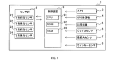
- a sensor control system 1 shown in FIG. 1 is mounted on a vehicle.
- the sensor control system 1 includes a sensor group 2, a camera 3, a GPS receiver 4, a storage device 5, a gyro sensor 6, a steering angle sensor 7, a winker sensor 8, and a control device 9.
- the vehicle on which the sensor control system 1 is mounted is referred to as “own vehicle”.
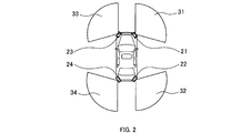
- Sensor group 2 includes a right front sensor 21, a right rear sensor 22, a left front sensor 23, and a left rear sensor 24.
- the sensors 21 to 24 are millimeter wave radars.
- the sensors 21 to 24 emit a millimeter-wave radar wave in a predetermined area around the host vehicle and receive the reflected wave, thereby making reference to the size of the object existing around the host vehicle and the host vehicle.
- the relative position, relative speed, etc. are detected.
- the right front sensor 21 is provided at the right front portion of the host vehicle, and monitors a right front area 31 of the host vehicle.
- the right rear sensor 22 is provided in the right rear part of the host vehicle, and monitors the right rear region 32 of the host vehicle.
- the left front sensor 23 is provided in the left front portion of the host vehicle, and monitors a left front region 33 of the host vehicle.
- the left rear sensor 24 is provided at the left rear portion of the host vehicle, and monitors a left rear region 34 of the host vehicle.
- the sensors 21 to 24 output the detection result to the control device 9.
- the camera 3 images the front of the host vehicle.
- the camera 3 outputs data representing the captured image to the control device 9.
- the GPS receiver 4 specifies the current position of the host vehicle by receiving a transmission radio wave from a GPS artificial satellite via a GPS antenna (not shown).
- the GPS receiver 4 outputs the current position of the host vehicle to the control device 9.
- the storage device 5 stores map data.
- the map data includes road information.
- the road information includes road link and node data. Information such as road shape, lanes, intersections, and pedestrian crossings is associated with road links and nodes.
- the gyro sensor 6 is a sensor configured to detect the rotational angular velocity of the host vehicle.
- the gyro sensor 6 outputs the detection result to the control device 9.
- the steering angle sensor 7 is a sensor configured to detect the steering angle of the host vehicle.
- the steering angle sensor 7 outputs the detection result to the control device 9.
- the turn signal sensor 8 is a sensor configured to detect the operation state of the turn signal switch of the host vehicle.
- the operation state of the turn signal switch in which the instruction direction is the right direction is referred to as a “right instruction state”.
- the operation state of the turn signal switch in which the instruction direction is the left direction is referred to as a “left instruction state”.
- an operation state of the blinker switch in which the instruction direction is neither the right direction nor the left direction is referred to as a “straight forward instruction state”.
- the winker sensor 8 outputs the detection result to the control device 9.
- the control device 9 includes a microcomputer including a CPU 91, a ROM 92, a RAM 93, and the like as constituent elements.
- the CPU 91 executes a program stored in a non-transitional physical storage medium such as the ROM 92. By executing this program, a method corresponding to the program is executed.
- control device 9 executes a detection process for detecting obstacles such as pedestrians and other vehicles with respect to the output value output from the sensor group 2. And the control apparatus 9 performs the collision avoidance control which avoids a collision, when these obstructions are detected.
- control device 9 executes a sensor control process shown in FIGS. 3 and 4 to be described later.
- priorities of the sensors 21 to 24 are set. Based on the set priority, the ratio of the processing amount of the detection processing to the output values output from the sensors 21 to 24 is changed.
- the control device 9 resets the priorities of all the sensors 21 to 24 to the initial values.
- the initial value is 1.
- the control device 9 specifies a predicted traveling direction that is a traveling direction of the host vehicle at a predetermined time point after the current time point.
- the predetermined time point after the current time point is set to be a point in time when the own vehicle is turning the intersection when the own vehicle is located before the intersection at the current time point.
- the control device 9 specifies the predicted traveling direction based on the detection result of the winker sensor 8. Specifically, when the operation state of the winker switch is the straight traveling instruction state at the time of executing S102, the predicted traveling direction is specified as the straight traveling direction. Further, when the operation state of the winker switch is the right instruction state when S102 is executed, the predicted traveling direction is specified as the right direction. Further, when the operation state of the winker switch is the left instruction state when S102 is executed, the predicted traveling direction is specified as the left direction.
- the control device 9 determines which of the straight traveling direction, the left direction, and the right direction is the predicted traveling direction. When determining that the predicted traveling direction is the straight traveling direction, the control device 9 proceeds to S106 described later. On the other hand, when the control device 9 determines that the predicted traveling direction is the right direction, the control device 9 proceeds to S104.
- control device 9 adds 1 to the priority of the right front sensor 21 and the right rear sensor 22 that monitor the right area of the host vehicle.
- control device 9 proceeds to S106 described later.
- control device 9 determines in S103 described above that the predicted traveling direction is the left direction, the control device 9 proceeds to S105.
- the control device 9 adds 1 to the priority of the left front sensor 23 and the left rear sensor 24 that monitor the left region of the host vehicle.
- the control device 9 proceeds to S106.
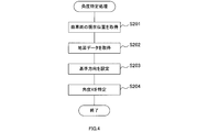
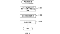
- This angle specifying process is a process of specifying an angle formed by a reference direction set based on a road around the host vehicle and the direction of the host vehicle. As will be described later, in the present embodiment, the direction of the oncoming lane is set as the reference direction.
- the angle specifying process will be specifically described with reference to the flowchart of FIG.
- the control device 9 acquires the current position of the host vehicle from the GPS receiver 4.
- the control device 9 acquires map data from the storage device 5.
- the control device 9 sets a reference direction based on the position of the host vehicle and the map data. Specifically, first, based on the road information included in the map data and the current position of the host vehicle, the host lane that is the lane in which the host vehicle is traveling is specified. And the direction of the opposite lane with respect to the own lane included in the map data is set as the reference direction.
- the opposite lane more generally, the direction of a certain lane means the direction in which the lane extends. In other words, the direction of the lane means a direction along a lane line that defines the lane (for example, a roadway center line).
- the reference direction is the direction of the oncoming lane on the road that the host vehicle was traveling just before entering the intersection until the predetermined switching timing.
- the reference direction is set to the direction of the oncoming lane on the road on which the host vehicle travels immediately after passing the intersection.
- the switching timing is the timing at which the predicted traveling direction is switched, specifically, the timing at which the operation state of the winker switch is switched from the right instruction state or the left instruction state to the straight traveling instruction state.
- the control device 9 specifies the angle X formed by the reference direction and the direction of the host vehicle. Specifically, first, the current direction of the host vehicle is calculated based on the detection result of the gyro sensor 6. Then, based on the calculated direction of the host vehicle and the set reference direction, an angle X formed by the reference direction and the direction of the host vehicle is specified.
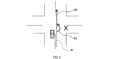
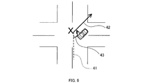
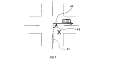
- the angle X is 180 degrees in a state where the reference direction and the direction of the host vehicle match. From this state, the angle X is set so as to decrease as the direction of the host vehicle tilts to the right with respect to the reference direction and increases as the vehicle tilts to the left. That is, as shown in FIGS. 6 and 7, the state where the direction of the host vehicle is tilted to the right with respect to the reference direction corresponds to a state where the angle X is smaller than 180 degrees. On the other hand, as shown in FIGS. 9 and 10, the state where the direction of the host vehicle is inclined to the left with respect to the reference direction corresponds to a state where the angle X is greater than 180 degrees.
- a straight line 41 indicated by a broken line indicates the direction of the oncoming lane set as the reference direction
- a straight arrow 42 indicated by a solid line indicates the direction of the host vehicle.
- a curved arrow 43 indicated by a solid line indicates the angle X.
- control device 9 When executing S204, the control device 9 ends the angle specifying process. And the control apparatus 9 will transfer to S107 of FIG. 3, after complete
- control device 9 adds (180 ⁇ X) / 90 the priority of the left front sensor 23 that monitors the left area of the host vehicle.
- control device 9 proceeds to S110 described later.
- control device 9 determines that the angle X is greater than 180 degrees in S107 described above, the control device 9 proceeds to S109.
- the control device 9 adds (X ⁇ 180) / 90 to the priority of the right front sensor 21 that monitors the right area of the host vehicle.
- the control device 9 proceeds to S110.
- the control device 9 executes control of the sensors 21 to 24 based on the priority.
- the control device 9 changes the ratio of the processing amount in the processing for detecting an obstacle based on the priority.
- the process of detecting the obstacle is executed for each of the plurality of output values output from the plurality of sensors 21 to 24.
- the control device 9 executes the same control as described in Japanese Patent No. 5327321. That is, the control device 9 changes the ratio of the processing amount by the following method.
- the control device 9 increases or decreases the cycle of processing each of the plurality of output values output from the sensors 21 to 24 according to the number of C bits in the sensors 21 to 24. Specifically, the control device 9 increases or decreases the processing cycle so that the greater the C, the shorter the cycle for processing the output value. As described above, the processing amount per unit time for the output values of the sensors 21 to 24 is changed by changing the processing cycle for the output values of the sensors 21 to 24 based on the priority.
- the control device 9 determines whether or not the ignition switch of the host vehicle is off. When it is determined that the ignition switch of the host vehicle is off, the control device 9 ends the sensor control process. On the other hand, when the control device 9 determines that the ignition switch of the host vehicle is not OFF, that is, is ON, the control device 9 proceeds to S101 described above, and executes the processing after S101 again.
- FIG. 5 shows a situation immediately after the host vehicle enters the intersection to turn right at the intersection.
- the operation state of the blinker switch is the right instruction state. Therefore, in the determination of S103 described above, it is determined that the predicted traveling direction is the right direction. As a result, the priority of the right front sensor 21 and the right rear sensor 22 is incremented by 1 in S104 described above.
- the priority of the right front sensor 21 and the right rear sensor 22 is incremented by 1 in S104 described above.
- the angle X formed by the opposite lane and the direction of the host vehicle is 180 degrees, it is determined in S107 described above that the angle X is 180 degrees or less.
- the priority of any sensor is not added. Therefore, in the situation shown in FIG. 5, the priority of the right front sensor 21 is 2, the priority of the right rear sensor 22 is 2, the priority of the left front sensor 23 is 1, and the priority of the left rear sensor 24 is 1. .
- FIG. 6 shows a situation where the host vehicle is turning right and the direction of the host vehicle is tilted to the right with respect to the direction of the oncoming lane.
- the operation state of the blinker switch is still the right instruction state. Therefore, 1 is added to the priorities of the right front sensor 21 and the right rear sensor 22 in S104 described above.
- FIG. 7 shows a situation in which the vehicle has completed a right turn and is about to leave the intersection.
- the operation state of the blinker switch is still the right instruction state. Therefore, 1 is added to the priorities of the right front sensor 21 and the right rear sensor 22 in S104 described above.
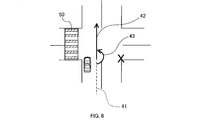
- FIG. 8 shows a situation immediately after the host vehicle enters the intersection to turn left at the intersection.
- the operation state of the blinker switch is the left instruction state. Therefore, in the determination of S103 described above, it is determined that the predicted traveling direction is the left direction. As a result, the priority of the left front sensor 23 and the left rear sensor 24 is incremented by 1 in S105 described above.
- the priority of the left front sensor 23 and the left rear sensor 24 is incremented by 1 in S105 described above.
- FIG. 9 shows a situation where the host vehicle is turning left and the direction of the host vehicle is tilted to the left with respect to the direction of the oncoming lane.
- the operation state of the blinker switch is still the left instruction state. Therefore, 1 is added to the priorities of the left front sensor 23 and the left rear sensor 24 in S105 described above.
- FIG. 10 shows a situation in which the vehicle has completed a left turn and is about to leave the intersection.
- the operation state of the blinker switch is still the left instruction state. Therefore, 1 is added to the priorities of the right front sensor 21 and the right rear sensor 22 in S105 described above.
- the control device 9 specifies an angle X formed by the direction of the oncoming lane and the direction of the host vehicle. Then, the control device 9 sets priorities of the plurality of sensors 21 to 24 according to the specified angle X. Then, the control device 9 changes the ratio of the processing amount with respect to the plurality of output values output from the plurality of sensors 21 to 24 based on the set priority.
- the priority can be changed according to the angle X. Therefore, the priority can be set appropriately according to the angle X. That is, when the host vehicle turns at an intersection or the like, the priority can be set appropriately. For this reason, it can suppress that the delay of the detection of a mobile body by the priority of a sensor being set improperly generate
- the priority of the left front sensor 23 is increased when the angle X is smaller than 180 degrees, that is, when the direction of the host vehicle is tilted to the right with respect to the direction of the oncoming lane.
- the priority of the right front sensor 21 is increased.
- the priority of the sensors 21 and 23 that monitor the area opposite to the traveling direction of the host vehicle is increased. Therefore, compared to a configuration in which the priority of only the sensor that monitors the area on the traveling direction side of the host vehicle is increased, a moving body such as an oncoming vehicle approaching the host vehicle from the side opposite to the traveling direction of the host vehicle is reduced. It can be easily detected.
- the direction of the oncoming lane is set as the reference direction. Therefore, it is possible to improve the detection accuracy of an oncoming vehicle, a bicycle traveling on a pedestrian crossing parallel to the oncoming lane, and the like. That is, the direction of the oncoming lane reflects the advancing direction of the oncoming vehicle and the advancing direction of a bicycle traveling on a pedestrian crossing parallel to the oncoming lane. Therefore, in this embodiment, a priority is set according to these traveling directions. That is, a priority level suitable for detecting oncoming vehicles, bicycles, and the like is set. Therefore, it is possible to improve the detection accuracy of an oncoming vehicle and a bicycle traveling on a pedestrian crossing parallel to the oncoming lane.
- the angle X is specified based on the current position of the host vehicle and map data. For example, when the direction of the oncoming lane is detected using a camera, the oncoming lane may not be detected when an obstacle such as a vehicle is present or when the host vehicle is traveling at night. On the other hand, according to the configuration of the present embodiment, the direction of the oncoming lane can be detected even when an obstacle such as a vehicle exists or when the host vehicle is traveling at night. For this reason, the reference direction can be detected more stably.
- control device 9 corresponds to a sensor control device
- the sensors 21 to 24 correspond to a plurality of sensors
- the left front sensor 23 corresponds to a left sensor
- the right front sensor 21 corresponds to a right sensor.
- the angle X corresponds to the direction of the vehicle specified by the specifying unit.
- S108 and S109 correspond to processing as a setting unit
- S110 corresponds to processing as an execution unit
- S201 corresponds to processing as a position acquisition unit
- S202 corresponds to processing as a map data acquisition unit.
- S204 corresponds to the processing as the specifying unit.
- the direction of the host vehicle relative to the reference direction is specified using the current position of the host vehicle and the map data.
- the second embodiment is different from the first embodiment in that the orientation of the host vehicle with respect to the reference direction is specified using the captured image of the camera 3.
- the sensor control system 1 of the second embodiment has the same hardware configuration as that of the first embodiment.
- the processing executed by the control device 9 of the second embodiment is partially different from that of the first embodiment. Specifically, only the angle specifying process executed in S106 of FIG. 3 described above is different from the first embodiment.
- the control device 9 acquires a captured image in front of the host vehicle from the camera 3.
- the control device 9 specifies an angle X formed by the reference direction and the direction of the host vehicle based on the acquired captured image. Specifically, the control device 9 performs image processing on the acquired captured image and detects the oncoming lane. Then, the control device 9 sets the detected direction of the oncoming lane as the reference direction. Further, the direction of the oncoming lane is detected as a relative direction with respect to the host vehicle in the captured image. Therefore, the detected direction of the oncoming lane is set as the reference direction, whereby the angle X formed by the reference direction and the direction of the host vehicle is specified.
- control device 9 specifies the angle X based on the captured image. Therefore, for example, the angle X can be specified with fewer errors compared to a configuration in which the angle X is specified using the GPS receiver 4 as in the first embodiment.
- S301 corresponds to processing as an image acquisition unit
- S302 corresponds to processing as a specifying unit.
- the direction of the host vehicle relative to the reference direction is specified using the current position of the host vehicle and the map data.
- the third embodiment is different from the first embodiment in that the direction of the host vehicle relative to the reference direction is specified using the operation state of the turn signal switch of the host vehicle and the steering angle of the host vehicle.
- the sensor control system 1 of the third embodiment has the same hardware configuration as that of the first embodiment.
- the processing executed by the control device 9 of the third embodiment is partially different from that of the first embodiment. Specifically, only the angle specifying process executed in S106 of FIG. 3 described above is different from the first embodiment.
- the control device 9 acquires the steering angle when the turn signal switch is operated.
- the steering angle when the turn signal switch of the host vehicle is most recently operated so that the operation state changes from the straight traveling instruction state to the right instruction state or the left instruction state is stored in the storage device 5. Yes.
- the control device 9 acquires the steering angle from the storage device 5.
- the steering angle at the time when the turn signal switch is operated is stored in the storage device 5, but the stored steering angle is not limited to this.
- the steering angle at a time slightly before and after the time when the turn signal switch is operated may be stored.
- the control device 9 acquires the current steering angle from the steering angle sensor 7.
- the control device 9 specifies the angle X based on the acquired current steering angle and the steering angle when the turn signal switch is operated.
- a change between the acquired current steering angle and the steering angle when the turn signal switch is operated is calculated. In other words, the amount of change in the steering angle up to the present is calculated based on the steering angle when the turn signal switch is operated. Then, the control device 9 specifies the change in the direction of the host vehicle according to the calculated change as the angle X.
- the turn signal switch when the turn signal switch is operated, it is estimated that the host vehicle is traveling along the reference direction. This is because when the turn signal switch is operated, the host vehicle is traveling in the host lane before the intersection, for example, and the direction of the host lane is considered to coincide with the direction of the opposite lane, that is, the reference direction. Then, it is estimated that the change in the steering angle from the time when the turn signal switch is operated corresponds to the angle X.
- the control device 9 specifies the angle X based on the change between the steering angle when the turn signal switch is operated and the current steering angle. Therefore, the angle X can be specified with a simple configuration.
- S401 corresponds to processing as the first steering angle acquisition unit
- S402 corresponds to processing as the second steering angle acquisition unit
- S403 corresponds to processing as the specifying unit.
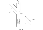
- the sensor control process based on the premise that the road is orthogonal at the intersection is illustrated, but the sensor control process is not limited to this.
- a general sensor control process including an intersection where two roads are not orthogonal, that is, an intersection where at least one of the angle C1 and the angle C2 is not 90 degrees may be executed.
- the angle C1 here is an angle formed by the direction of the road on which the host vehicle is traveling immediately before the host vehicle enters the intersection and the direction of the road that intersects the intersection from the right.
- the angle C2 here is an angle formed by the direction of the road on which the host vehicle is traveling immediately before the host vehicle enters the intersection and the direction of the road that intersects the intersection from the left.
- the solid line 61 indicates the direction of the road on which the host vehicle is traveling immediately before the host vehicle enters the intersection.
- a broken line 62 indicates the direction of the road that intersects the intersection from the right.
- a broken line 63 indicates the direction of the road that intersects the intersection from the left.
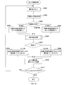
- control device 9 may execute a sensor control process of FIG. 15 described below. Steps S501 to S507 are the same as steps S101 to S107 in FIG.
- control device 9 determines in S507 that the angle X is 180 degrees or less, the control device 9 proceeds to S508.
- the control device 9 adds (180 ⁇ X) / C1 to the priority of the left front sensor 23 that monitors the left area of the host vehicle.
- the control device 9 proceeds to S510.
- step S509 the control device 9 adds (X ⁇ 180) / C2 to the priority of the right front sensor 21 that monitors the right area of the host vehicle. After executing S509, the control device 9 proceeds to S510.
- S510 and S511 are the same as S110 and S111 in FIG.
- S508 and S509 correspond to processing as a setting unit
- S510 corresponds to processing as an execution unit.
- the sensors 21 to 24 are millimeter wave radars, but the type of sensor is not limited to this.
- the sensor may be, for example, a laser radar or an image sensor such as a camera.
- the vehicle is equipped with the right front sensor 21 or the like that monitors the right front area of the vehicle, but the sensor mounted on the vehicle is not limited to this.
- the vehicle may be equipped with a right side sensor that monitors a region on the right side of the vehicle, a left side sensor that monitors a region on the left side of the vehicle, and the like.
- the predicted traveling direction is specified based on the detection result of the winker sensor 8, but the method for specifying the predicted traveling direction is not limited to this.
- the predicted traveling direction may be specified based on, for example, the driver's line of sight. Further, for example, the predicted traveling direction may be specified by estimating the position of the host vehicle on the road. Specifically, for example, when it is determined using the camera 3, the GPS receiver 4, and the storage device 5 that the host vehicle is located in the right turn lane or the left turn lane, the predicted traveling direction is the right direction or You may specify that it is the left direction.
- the switching timing of the reference direction at the intersection is not limited to those in the above embodiments.
- the reference direction may be switched when the camera 3 detects a lane marking on a road that runs immediately after the host vehicle passes through an intersection.
- the reference direction can be switched. May be.
- the direction of the oncoming lane is set as the reference direction, but the direction set as the reference direction is not limited to this.
- the direction of the own lane may be set as the reference direction.
- the direction of the pedestrian crossing 50 parallel to the own lane or the opposite lane shown in FIGS. 8 to 10 may be set as the reference direction.
- “parallel” is not limited to parallel in a strict sense, and may not be strictly parallel as long as the desired effect is achieved.
- the same effect as the effect (1d) of the first embodiment described above can be obtained. it can.
- the processing amount for the output values of the sensors 21 to 24 is changed by changing the processing cycle for the output values of the sensors 21 to 24.
- the configuration to be changed is not limited to this.
- the processing amount in a predetermined time may be changed by changing the processing amount per time while keeping the processing cycle constant.
- the ratio of the processing amount to the output values of the sensors 21 to 24 is changed based on the priority, but the control based on the priority is not limited to this.
- the ratio of the operation performance of the plurality of sensors 21 to 24 may be changed based on the priority.
- the detection accuracy of the sensors 21 to 24 may be changed as the operation performance.
- the operation of the sensors 21 to 24 may be controlled so that the higher the priority is, the higher the detection accuracy of the sensor is. According to such a configuration, the higher the priority, the higher the detection accuracy of the sensor.
- a sensor with a high priority performs monitoring with the required high detection accuracy
- a sensor with a low priority performs monitoring with a low detection accuracy with a low load on the CPU 91 and the in-vehicle LAN. Therefore, in the case where a plurality of sensors 21 to 24 are used, the load on the CPU 91 and the in-vehicle LAN can be reduced and the surroundings of the host vehicle can be appropriately adjusted as compared with the configuration in which all the sensors 21 to 24 monitor with high detection accuracy. Can be monitored.
- the control for changing the detection accuracy of the sensor is, for example, the following control. That is, for example, in FMCW radar, a beat signal generated from a transmission / reception wave is subjected to a fast Fourier transform (FFT), and a peak signal component is extracted from the processing result. Then, based on the extraction result, the distance from the target reflecting the radar wave is calculated.
- FFT fast Fourier transform
- control for changing the detection accuracy of the sensor control for changing the extraction reference when extracting peaks that can be candidates for various targets from the FFT processing result can be considered.
- control for changing the detection accuracy of the sensor control for changing the frequency range for performing the peak search, control for changing the frequency resolution of the FFT, and the like can be considered.
- control for changing the frequency resolution of the FFT control for changing the frequency resolution of the FFT, and the like can be considered.
- a part or all of the functions executed by the control device 9 may be configured by one or more ICs as hardware.
- the sensor control system 1 having the control device 9 as a constituent element, a program for causing a computer to function as the control device 9, a non-transitive semiconductor memory or the like storing the program
- the present disclosure can also be realized in various forms, such as a method of setting the priority according to the substantial storage medium and the vehicle direction with respect to the reference direction.
Landscapes
- Engineering & Computer Science (AREA)
- Automation & Control Theory (AREA)
- Transportation (AREA)
- Mechanical Engineering (AREA)
- Physics & Mathematics (AREA)
- General Physics & Mathematics (AREA)
- Human Computer Interaction (AREA)
- Chemical & Material Sciences (AREA)
- Combustion & Propulsion (AREA)
- Mathematical Physics (AREA)
- Traffic Control Systems (AREA)
- Control Of Driving Devices And Active Controlling Of Vehicle (AREA)
Abstract
Dans la présente invention, une unité d'exécution (S110) est conçue pour exécuter une commande des performances de fonctionnement de multiples capteurs afin de surveiller différentes zones autour d'un véhicule et/ou un traitement prédéterminé de multiples valeurs de sortie délivrées par les multiples capteurs. Une unité de détermination est conçue de manière à déterminer l'orientation du véhicule par rapport à une direction de référence prédéfinie sur la base de routes à proximité du véhicule. Une unité de définition (S108, S109) est conçue de manière à définir les priorités des multiples capteurs en fonction de l'orientation du véhicule déterminée par l'unité de détermination. L'unité d'exécution modifie les rapports des performances de fonctionnement des multiples capteurs et/ou les rapports des quantités de traitement des multiples valeurs de sortie sur la base des priorités.
Priority Applications (2)
| Application Number | Priority Date | Filing Date | Title |
|---|---|---|---|
| CN201780064864.1A CN109844844B (zh) | 2016-10-21 | 2017-10-16 | 传感器控制装置 |
| US16/343,129 US11208114B2 (en) | 2016-10-21 | 2017-10-16 | Sensor control apparatus |
Applications Claiming Priority (2)
| Application Number | Priority Date | Filing Date | Title |
|---|---|---|---|
| JP2016206888A JP6654544B2 (ja) | 2016-10-21 | 2016-10-21 | センサ制御装置 |
| JP2016-206888 | 2016-10-21 |
Publications (1)
| Publication Number | Publication Date |
|---|---|
| WO2018074426A1 true WO2018074426A1 (fr) | 2018-04-26 |
Family
ID=62018656
Family Applications (1)
| Application Number | Title | Priority Date | Filing Date |
|---|---|---|---|
| PCT/JP2017/037404 WO2018074426A1 (fr) | 2016-10-21 | 2017-10-16 | Dispositif de commande de capteur |
Country Status (4)
| Country | Link |
|---|---|
| US (1) | US11208114B2 (fr) |
| JP (1) | JP6654544B2 (fr) |
| CN (1) | CN109844844B (fr) |
| WO (1) | WO2018074426A1 (fr) |
Cited By (1)
| Publication number | Priority date | Publication date | Assignee | Title |
|---|---|---|---|---|
| CN112805590A (zh) * | 2018-10-12 | 2021-05-14 | 京瓷株式会社 | 电子设备、电子设备的控制方法以及电子设备的控制程序 |
Families Citing this family (9)
| Publication number | Priority date | Publication date | Assignee | Title |
|---|---|---|---|---|
| KR102371616B1 (ko) * | 2017-11-07 | 2022-03-07 | 현대자동차주식회사 | 차량의 센서 데이터 연계 장치 및 방법 |
| JP6861620B2 (ja) * | 2017-12-15 | 2021-04-21 | 株式会社シマノ | 検出装置および制御システム |
| KR102659057B1 (ko) * | 2018-12-12 | 2024-04-19 | 현대자동차주식회사 | 데이터 처리 연산량 최적화 장치 및 그 방법 |
| WO2021106039A1 (fr) * | 2019-11-25 | 2021-06-03 | 三菱電機株式会社 | Dispositif de détection d'objet |
| US11930514B2 (en) * | 2020-06-26 | 2024-03-12 | Qualcomm Incorporated | Position-aware resource allocation for a wireless in-vehicle network |
| SE544537C2 (en) * | 2020-11-10 | 2022-07-05 | Scania Cv Ab | Multi-modality corner vehicle sensor module |
| US11747438B1 (en) * | 2021-01-07 | 2023-09-05 | Bae Systems Information And Electronic Systems Integration Inc. | Cognitive electronic warfare scheduler |
| US11851051B2 (en) * | 2021-07-28 | 2023-12-26 | Toyota Motor Engineering & Manufacturing North America, Inc. | System and method for detecting an object in a turning alert zone of a vehicle |
| US20230256988A1 (en) * | 2022-02-17 | 2023-08-17 | Gm Cruise Holdings Llc | Dynamic lidar adjustments based on av road conditions |
Citations (5)
| Publication number | Priority date | Publication date | Assignee | Title |
|---|---|---|---|---|
| JPH05238314A (ja) * | 1992-02-28 | 1993-09-17 | Honda Motor Co Ltd | 車両用周囲監視装置 |
| JP2008152390A (ja) * | 2006-12-14 | 2008-07-03 | Toyota Motor Corp | 車両用周辺監視装置 |
| JP2008256620A (ja) * | 2007-04-06 | 2008-10-23 | Matsushita Electric Ind Co Ltd | 地図データ修正装置、地図データ修正方法、及び地図データ修正プログラム |
| WO2010140239A1 (fr) * | 2009-06-04 | 2010-12-09 | トヨタ自動車株式会社 | Dispositif de contrôle d'environnement d'un véhicule et procédé pour contrôler l'environnement utilisé par ce véhicule |
| JP2012045984A (ja) * | 2010-08-24 | 2012-03-08 | Mitsubishi Motors Corp | 衝突軽減装置 |
Family Cites Families (10)
| Publication number | Priority date | Publication date | Assignee | Title |
|---|---|---|---|---|
| CN101356078B (zh) * | 2005-12-12 | 2012-07-18 | 松下电器产业株式会社 | 安全行驶辅助装置 |
| US9302678B2 (en) * | 2006-12-29 | 2016-04-05 | Robotic Research, Llc | Robotic driving system |
| JP5015849B2 (ja) * | 2008-04-11 | 2012-08-29 | トヨタ自動車株式会社 | 逆走警告装置、逆走警告方法 |
| MX2011005942A (es) * | 2008-12-04 | 2011-07-28 | Crown Equip Corp | Percepcion de zonas multiples para vehiculos de manejo de materiales (montacargas). |
| US9135825B2 (en) * | 2010-02-22 | 2015-09-15 | Toyota Jidosha Kabushiki Kaisha | Risk degree calculation device |
| JP5862670B2 (ja) * | 2011-08-02 | 2016-02-16 | 日産自動車株式会社 | 走行支援装置および走行支援方法 |
| KR102074811B1 (ko) * | 2012-07-17 | 2020-02-10 | 한국전자통신연구원 | 교차로 운행 정보 제공 장치 및 방법 |
| US9555801B2 (en) * | 2014-03-05 | 2017-01-31 | Denso International America, Inc. | Active steering safety system |
| US20160231746A1 (en) * | 2015-02-06 | 2016-08-11 | Delphi Technologies, Inc. | System And Method To Operate An Automated Vehicle |
| EP3159853B1 (fr) * | 2015-10-23 | 2019-03-27 | Harman International Industries, Incorporated | Systèmes et procédés d'analyse avancée d'assistance au conducteur |
-
2016
- 2016-10-21 JP JP2016206888A patent/JP6654544B2/ja active Active
-
2017
- 2017-10-16 US US16/343,129 patent/US11208114B2/en active Active
- 2017-10-16 CN CN201780064864.1A patent/CN109844844B/zh active Active
- 2017-10-16 WO PCT/JP2017/037404 patent/WO2018074426A1/fr active Application Filing
Patent Citations (5)
| Publication number | Priority date | Publication date | Assignee | Title |
|---|---|---|---|---|
| JPH05238314A (ja) * | 1992-02-28 | 1993-09-17 | Honda Motor Co Ltd | 車両用周囲監視装置 |
| JP2008152390A (ja) * | 2006-12-14 | 2008-07-03 | Toyota Motor Corp | 車両用周辺監視装置 |
| JP2008256620A (ja) * | 2007-04-06 | 2008-10-23 | Matsushita Electric Ind Co Ltd | 地図データ修正装置、地図データ修正方法、及び地図データ修正プログラム |
| WO2010140239A1 (fr) * | 2009-06-04 | 2010-12-09 | トヨタ自動車株式会社 | Dispositif de contrôle d'environnement d'un véhicule et procédé pour contrôler l'environnement utilisé par ce véhicule |
| JP2012045984A (ja) * | 2010-08-24 | 2012-03-08 | Mitsubishi Motors Corp | 衝突軽減装置 |
Cited By (2)
| Publication number | Priority date | Publication date | Assignee | Title |
|---|---|---|---|---|
| CN112805590A (zh) * | 2018-10-12 | 2021-05-14 | 京瓷株式会社 | 电子设备、电子设备的控制方法以及电子设备的控制程序 |
| EP3865907A4 (fr) * | 2018-10-12 | 2022-09-14 | Kyocera Corporation | Dispositif électronique, procédé de commande de dispositif électronique et programme de commande de dispositif électronique |
Also Published As
| Publication number | Publication date |
|---|---|
| JP6654544B2 (ja) | 2020-02-26 |
| US11208114B2 (en) | 2021-12-28 |
| JP2018067237A (ja) | 2018-04-26 |
| CN109844844A (zh) | 2019-06-04 |
| CN109844844B (zh) | 2022-05-17 |
| US20190315373A1 (en) | 2019-10-17 |
Similar Documents
| Publication | Publication Date | Title |
|---|---|---|
| WO2018074426A1 (fr) | Dispositif de commande de capteur | |
| US9150223B2 (en) | Collision mitigation apparatus | |
| US10332400B2 (en) | Intra-lane travel control apparatus and intra-lane travel control method | |
| US9463796B2 (en) | Driving assistance apparatus | |
| JP5724955B2 (ja) | 物体検出装置、情報処理装置、物体検出方法 | |
| JP6269552B2 (ja) | 車両走行制御装置 | |
| JP7020130B2 (ja) | 車両制御装置、方法、およびプログラム | |
| US9830822B2 (en) | Driving assistance apparatus | |
| EP2482250A1 (fr) | Dispositif de détection d'objets | |
| US11092442B2 (en) | Host vehicle position estimation device | |
| WO2016181618A1 (fr) | Dispositif d'établissement de zone surveillée et procédé d'établissement de zone surveillée | |
| JP7145034B2 (ja) | 運転支援装置 | |
| JP7059786B2 (ja) | 車外報知装置 | |
| JP7275623B2 (ja) | 運転支援装置 | |
| JP6544168B2 (ja) | 車両制御装置、及び車両制御方法 | |
| US20190176887A1 (en) | Recognition device and recognition method | |
| EP3912877B1 (fr) | Procédé d'aide à la conduite et dispositif d'aide à la conduite | |
| JP5606468B2 (ja) | 車両周辺監視装置 | |
| US20230227030A1 (en) | Vehicle control device | |
| JP6733616B2 (ja) | 車両制御装置 | |
| JP2019197270A (ja) | 物体検知装置および物体検知方法 | |
| US20230031419A1 (en) | Preceding vehicle determination system and preceding vehicle determination method | |
| JP7236279B2 (ja) | 走行支援方法及び走行支援装置 | |
| JP6930483B2 (ja) | 走行制御装置 | |
| JP2019215177A (ja) | 軌道設定装置 |
Legal Events
| Date | Code | Title | Description |
|---|---|---|---|
| 121 | Ep: the epo has been informed by wipo that ep was designated in this application |
Ref document number: 17862127 Country of ref document: EP Kind code of ref document: A1 |
|
| NENP | Non-entry into the national phase |
Ref country code: DE |
|
| 122 | Ep: pct application non-entry in european phase |
Ref document number: 17862127 Country of ref document: EP Kind code of ref document: A1 |