WO2018074426A1 - Sensor control device - Google Patents
Sensor control device Download PDFInfo
- Publication number
- WO2018074426A1 WO2018074426A1 PCT/JP2017/037404 JP2017037404W WO2018074426A1 WO 2018074426 A1 WO2018074426 A1 WO 2018074426A1 JP 2017037404 W JP2017037404 W JP 2017037404W WO 2018074426 A1 WO2018074426 A1 WO 2018074426A1
- Authority
- WO
- WIPO (PCT)
- Prior art keywords
- sensor
- vehicle
- control device
- priority
- sensor control
- Prior art date
Links
- 238000012545 processing Methods 0.000 claims abstract description 54
- 238000012544 monitoring process Methods 0.000 claims abstract description 8
- 238000001514 detection method Methods 0.000 claims description 33
- 238000000034 method Methods 0.000 description 34
- 230000000694 effects Effects 0.000 description 11
- 239000000470 constituent Substances 0.000 description 10
- 230000007423 decrease Effects 0.000 description 3
- 230000005540 biological transmission Effects 0.000 description 2
- 230000003111 delayed effect Effects 0.000 description 2
- 238000000605 extraction Methods 0.000 description 2
- 238000013459 approach Methods 0.000 description 1
- 238000010586 diagram Methods 0.000 description 1
- 238000012986 modification Methods 0.000 description 1
- 230000004048 modification Effects 0.000 description 1
- 239000004065 semiconductor Substances 0.000 description 1
- 238000012546 transfer Methods 0.000 description 1
Images


Classifications
-
- B—PERFORMING OPERATIONS; TRANSPORTING
- B60—VEHICLES IN GENERAL
- B60W—CONJOINT CONTROL OF VEHICLE SUB-UNITS OF DIFFERENT TYPE OR DIFFERENT FUNCTION; CONTROL SYSTEMS SPECIALLY ADAPTED FOR HYBRID VEHICLES; ROAD VEHICLE DRIVE CONTROL SYSTEMS FOR PURPOSES NOT RELATED TO THE CONTROL OF A PARTICULAR SUB-UNIT
- B60W50/00—Details of control systems for road vehicle drive control not related to the control of a particular sub-unit, e.g. process diagnostic or vehicle driver interfaces
- B60W50/06—Improving the dynamic response of the control system, e.g. improving the speed of regulation or avoiding hunting or overshoot
-
- B—PERFORMING OPERATIONS; TRANSPORTING
- B60—VEHICLES IN GENERAL
- B60W—CONJOINT CONTROL OF VEHICLE SUB-UNITS OF DIFFERENT TYPE OR DIFFERENT FUNCTION; CONTROL SYSTEMS SPECIALLY ADAPTED FOR HYBRID VEHICLES; ROAD VEHICLE DRIVE CONTROL SYSTEMS FOR PURPOSES NOT RELATED TO THE CONTROL OF A PARTICULAR SUB-UNIT
- B60W40/00—Estimation or calculation of non-directly measurable driving parameters for road vehicle drive control systems not related to the control of a particular sub unit, e.g. by using mathematical models
- B60W40/10—Estimation or calculation of non-directly measurable driving parameters for road vehicle drive control systems not related to the control of a particular sub unit, e.g. by using mathematical models related to vehicle motion
-
- B—PERFORMING OPERATIONS; TRANSPORTING
- B60—VEHICLES IN GENERAL
- B60W—CONJOINT CONTROL OF VEHICLE SUB-UNITS OF DIFFERENT TYPE OR DIFFERENT FUNCTION; CONTROL SYSTEMS SPECIALLY ADAPTED FOR HYBRID VEHICLES; ROAD VEHICLE DRIVE CONTROL SYSTEMS FOR PURPOSES NOT RELATED TO THE CONTROL OF A PARTICULAR SUB-UNIT
- B60W30/00—Purposes of road vehicle drive control systems not related to the control of a particular sub-unit, e.g. of systems using conjoint control of vehicle sub-units, or advanced driver assistance systems for ensuring comfort, stability and safety or drive control systems for propelling or retarding the vehicle
- B60W30/08—Active safety systems predicting or avoiding probable or impending collision or attempting to minimise its consequences
- B60W30/095—Predicting travel path or likelihood of collision
- B60W30/0953—Predicting travel path or likelihood of collision the prediction being responsive to vehicle dynamic parameters
-
- B—PERFORMING OPERATIONS; TRANSPORTING
- B60—VEHICLES IN GENERAL
- B60W—CONJOINT CONTROL OF VEHICLE SUB-UNITS OF DIFFERENT TYPE OR DIFFERENT FUNCTION; CONTROL SYSTEMS SPECIALLY ADAPTED FOR HYBRID VEHICLES; ROAD VEHICLE DRIVE CONTROL SYSTEMS FOR PURPOSES NOT RELATED TO THE CONTROL OF A PARTICULAR SUB-UNIT
- B60W30/00—Purposes of road vehicle drive control systems not related to the control of a particular sub-unit, e.g. of systems using conjoint control of vehicle sub-units, or advanced driver assistance systems for ensuring comfort, stability and safety or drive control systems for propelling or retarding the vehicle
- B60W30/10—Path keeping
- B60W30/12—Lane keeping
-
- B—PERFORMING OPERATIONS; TRANSPORTING
- B60—VEHICLES IN GENERAL
- B60W—CONJOINT CONTROL OF VEHICLE SUB-UNITS OF DIFFERENT TYPE OR DIFFERENT FUNCTION; CONTROL SYSTEMS SPECIALLY ADAPTED FOR HYBRID VEHICLES; ROAD VEHICLE DRIVE CONTROL SYSTEMS FOR PURPOSES NOT RELATED TO THE CONTROL OF A PARTICULAR SUB-UNIT
- B60W50/00—Details of control systems for road vehicle drive control not related to the control of a particular sub-unit, e.g. process diagnostic or vehicle driver interfaces
- B60W50/0097—Predicting future conditions
-
- B—PERFORMING OPERATIONS; TRANSPORTING
- B62—LAND VEHICLES FOR TRAVELLING OTHERWISE THAN ON RAILS
- B62D—MOTOR VEHICLES; TRAILERS
- B62D15/00—Steering not otherwise provided for
- B62D15/02—Steering position indicators ; Steering position determination; Steering aids
- B62D15/021—Determination of steering angle
-
- G—PHYSICS
- G07—CHECKING-DEVICES
- G07C—TIME OR ATTENDANCE REGISTERS; REGISTERING OR INDICATING THE WORKING OF MACHINES; GENERATING RANDOM NUMBERS; VOTING OR LOTTERY APPARATUS; ARRANGEMENTS, SYSTEMS OR APPARATUS FOR CHECKING NOT PROVIDED FOR ELSEWHERE
- G07C5/00—Registering or indicating the working of vehicles
- G07C5/02—Registering or indicating driving, working, idle, or waiting time only
-
- G—PHYSICS
- G07—CHECKING-DEVICES
- G07C—TIME OR ATTENDANCE REGISTERS; REGISTERING OR INDICATING THE WORKING OF MACHINES; GENERATING RANDOM NUMBERS; VOTING OR LOTTERY APPARATUS; ARRANGEMENTS, SYSTEMS OR APPARATUS FOR CHECKING NOT PROVIDED FOR ELSEWHERE
- G07C5/00—Registering or indicating the working of vehicles
- G07C5/08—Registering or indicating performance data other than driving, working, idle, or waiting time, with or without registering driving, working, idle or waiting time
-
- G—PHYSICS
- G08—SIGNALLING
- G08G—TRAFFIC CONTROL SYSTEMS
- G08G1/00—Traffic control systems for road vehicles
- G08G1/16—Anti-collision systems
-
- B—PERFORMING OPERATIONS; TRANSPORTING
- B60—VEHICLES IN GENERAL
- B60W—CONJOINT CONTROL OF VEHICLE SUB-UNITS OF DIFFERENT TYPE OR DIFFERENT FUNCTION; CONTROL SYSTEMS SPECIALLY ADAPTED FOR HYBRID VEHICLES; ROAD VEHICLE DRIVE CONTROL SYSTEMS FOR PURPOSES NOT RELATED TO THE CONTROL OF A PARTICULAR SUB-UNIT
- B60W50/00—Details of control systems for road vehicle drive control not related to the control of a particular sub-unit, e.g. process diagnostic or vehicle driver interfaces
- B60W2050/0062—Adapting control system settings
- B60W2050/0075—Automatic parameter input, automatic initialising or calibrating means
- B60W2050/0083—Setting, resetting, calibration
- B60W2050/0086—Recalibrating datum positions, e.g. by using check cycles
-
- B—PERFORMING OPERATIONS; TRANSPORTING
- B60—VEHICLES IN GENERAL
- B60W—CONJOINT CONTROL OF VEHICLE SUB-UNITS OF DIFFERENT TYPE OR DIFFERENT FUNCTION; CONTROL SYSTEMS SPECIALLY ADAPTED FOR HYBRID VEHICLES; ROAD VEHICLE DRIVE CONTROL SYSTEMS FOR PURPOSES NOT RELATED TO THE CONTROL OF A PARTICULAR SUB-UNIT
- B60W50/00—Details of control systems for road vehicle drive control not related to the control of a particular sub-unit, e.g. process diagnostic or vehicle driver interfaces
- B60W50/06—Improving the dynamic response of the control system, e.g. improving the speed of regulation or avoiding hunting or overshoot
- B60W2050/065—Improving the dynamic response of the control system, e.g. improving the speed of regulation or avoiding hunting or overshoot by reducing the computational load on the digital processor of the control computer
-
- B—PERFORMING OPERATIONS; TRANSPORTING
- B60—VEHICLES IN GENERAL
- B60W—CONJOINT CONTROL OF VEHICLE SUB-UNITS OF DIFFERENT TYPE OR DIFFERENT FUNCTION; CONTROL SYSTEMS SPECIALLY ADAPTED FOR HYBRID VEHICLES; ROAD VEHICLE DRIVE CONTROL SYSTEMS FOR PURPOSES NOT RELATED TO THE CONTROL OF A PARTICULAR SUB-UNIT
- B60W2420/00—Indexing codes relating to the type of sensors based on the principle of their operation
- B60W2420/40—Photo or light sensitive means, e.g. infrared sensors
- B60W2420/403—Image sensing, e.g. optical camera
-
- B60W2420/408—
-
- B—PERFORMING OPERATIONS; TRANSPORTING
- B60—VEHICLES IN GENERAL
- B60W—CONJOINT CONTROL OF VEHICLE SUB-UNITS OF DIFFERENT TYPE OR DIFFERENT FUNCTION; CONTROL SYSTEMS SPECIALLY ADAPTED FOR HYBRID VEHICLES; ROAD VEHICLE DRIVE CONTROL SYSTEMS FOR PURPOSES NOT RELATED TO THE CONTROL OF A PARTICULAR SUB-UNIT
- B60W2510/00—Input parameters relating to a particular sub-units
- B60W2510/20—Steering systems
-
- B—PERFORMING OPERATIONS; TRANSPORTING
- B60—VEHICLES IN GENERAL
- B60W—CONJOINT CONTROL OF VEHICLE SUB-UNITS OF DIFFERENT TYPE OR DIFFERENT FUNCTION; CONTROL SYSTEMS SPECIALLY ADAPTED FOR HYBRID VEHICLES; ROAD VEHICLE DRIVE CONTROL SYSTEMS FOR PURPOSES NOT RELATED TO THE CONTROL OF A PARTICULAR SUB-UNIT
- B60W2520/00—Input parameters relating to overall vehicle dynamics
- B60W2520/06—Direction of travel
-
- B—PERFORMING OPERATIONS; TRANSPORTING
- B60—VEHICLES IN GENERAL
- B60W—CONJOINT CONTROL OF VEHICLE SUB-UNITS OF DIFFERENT TYPE OR DIFFERENT FUNCTION; CONTROL SYSTEMS SPECIALLY ADAPTED FOR HYBRID VEHICLES; ROAD VEHICLE DRIVE CONTROL SYSTEMS FOR PURPOSES NOT RELATED TO THE CONTROL OF A PARTICULAR SUB-UNIT
- B60W2520/00—Input parameters relating to overall vehicle dynamics
- B60W2520/10—Longitudinal speed
-
- B—PERFORMING OPERATIONS; TRANSPORTING
- B60—VEHICLES IN GENERAL
- B60W—CONJOINT CONTROL OF VEHICLE SUB-UNITS OF DIFFERENT TYPE OR DIFFERENT FUNCTION; CONTROL SYSTEMS SPECIALLY ADAPTED FOR HYBRID VEHICLES; ROAD VEHICLE DRIVE CONTROL SYSTEMS FOR PURPOSES NOT RELATED TO THE CONTROL OF A PARTICULAR SUB-UNIT
- B60W2554/00—Input parameters relating to objects
- B60W2554/40—Dynamic objects, e.g. animals, windblown objects
- B60W2554/402—Type
- B60W2554/4026—Cycles
-
- B—PERFORMING OPERATIONS; TRANSPORTING
- B60—VEHICLES IN GENERAL
- B60W—CONJOINT CONTROL OF VEHICLE SUB-UNITS OF DIFFERENT TYPE OR DIFFERENT FUNCTION; CONTROL SYSTEMS SPECIALLY ADAPTED FOR HYBRID VEHICLES; ROAD VEHICLE DRIVE CONTROL SYSTEMS FOR PURPOSES NOT RELATED TO THE CONTROL OF A PARTICULAR SUB-UNIT
- B60W2554/00—Input parameters relating to objects
- B60W2554/80—Spatial relation or speed relative to objects
Definitions
- the present disclosure relates to a sensor control device.
- Patent Document 1 discloses a sensor control device that controls detection accuracy of a plurality of sensors that monitor different regions around a vehicle and a processing cycle for a plurality of output values output from the plurality of sensors. ing.
- the priority of a plurality of sensors is set for the purpose of reducing the load on the CPU and the in-vehicle LAN.
- the priority is set based on the traveling direction of the vehicle. That is, first, the traveling direction of the vehicle is determined based on the movement of the vehicle and the line of sight of the driver. When the result of the determination indicates that the traveling direction of the vehicle is the right direction, the priority of the sensor that monitors the region on the right side of the vehicle is increased. On the other hand, when the determination result indicates that the traveling direction of the vehicle is the left direction, the priority of the sensor that monitors the left region of the vehicle is increased. And it changes so that a sensor detection accuracy may become high, so that a sensor with high priority. Further, the higher the priority, the shorter the processing cycle for the sensor output value.
- One aspect of the present disclosure is to suppress the occurrence of a delay in detection of a moving object due to inappropriate setting of sensor priorities.
- One aspect of the present disclosure is a sensor control device including an execution unit, a specifying unit, and a setting unit.
- the execution unit executes at least one of control of operation performance of the plurality of sensors that monitor different regions around the vehicle and predetermined processing for each of the plurality of output values output from the plurality of sensors. Configured as follows.
- the specifying unit is configured to specify a direction of the vehicle with respect to a reference direction set based on a road around the vehicle.
- the setting unit is configured to set priorities of the plurality of sensors according to the direction of the vehicle specified by the specifying unit.
- the execution unit changes at least one of the ratio of the operation performance of the plurality of sensors and the ratio of the processing amount to the plurality of output values based on the priority.
- the priority can be changed according to the direction of the vehicle with respect to the reference direction. Therefore, the priority can be appropriately set according to the direction of the vehicle with respect to the reference direction. That is, for example, when the vehicle turns, priority can be set appropriately. Therefore, it is possible to suppress the occurrence of a delay in detection of the moving object due to inappropriate setting of the sensor priority.
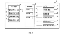
- a sensor control system 1 shown in FIG. 1 is mounted on a vehicle.
- the sensor control system 1 includes a sensor group 2, a camera 3, a GPS receiver 4, a storage device 5, a gyro sensor 6, a steering angle sensor 7, a winker sensor 8, and a control device 9.
- the vehicle on which the sensor control system 1 is mounted is referred to as “own vehicle”.
- Sensor group 2 includes a right front sensor 21, a right rear sensor 22, a left front sensor 23, and a left rear sensor 24.
- the sensors 21 to 24 are millimeter wave radars.
- the sensors 21 to 24 emit a millimeter-wave radar wave in a predetermined area around the host vehicle and receive the reflected wave, thereby making reference to the size of the object existing around the host vehicle and the host vehicle.
- the relative position, relative speed, etc. are detected.
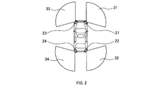
- the right front sensor 21 is provided at the right front portion of the host vehicle, and monitors a right front area 31 of the host vehicle.
- the right rear sensor 22 is provided in the right rear part of the host vehicle, and monitors the right rear region 32 of the host vehicle.
- the left front sensor 23 is provided in the left front portion of the host vehicle, and monitors a left front region 33 of the host vehicle.
- the left rear sensor 24 is provided at the left rear portion of the host vehicle, and monitors a left rear region 34 of the host vehicle.
- the sensors 21 to 24 output the detection result to the control device 9.
- the camera 3 images the front of the host vehicle.
- the camera 3 outputs data representing the captured image to the control device 9.
- the GPS receiver 4 specifies the current position of the host vehicle by receiving a transmission radio wave from a GPS artificial satellite via a GPS antenna (not shown).
- the GPS receiver 4 outputs the current position of the host vehicle to the control device 9.
- the storage device 5 stores map data.
- the map data includes road information.
- the road information includes road link and node data. Information such as road shape, lanes, intersections, and pedestrian crossings is associated with road links and nodes.
- the gyro sensor 6 is a sensor configured to detect the rotational angular velocity of the host vehicle.
- the gyro sensor 6 outputs the detection result to the control device 9.
- the steering angle sensor 7 is a sensor configured to detect the steering angle of the host vehicle.
- the steering angle sensor 7 outputs the detection result to the control device 9.
- the turn signal sensor 8 is a sensor configured to detect the operation state of the turn signal switch of the host vehicle.
- the operation state of the turn signal switch in which the instruction direction is the right direction is referred to as a “right instruction state”.
- the operation state of the turn signal switch in which the instruction direction is the left direction is referred to as a “left instruction state”.
- an operation state of the blinker switch in which the instruction direction is neither the right direction nor the left direction is referred to as a “straight forward instruction state”.
- the winker sensor 8 outputs the detection result to the control device 9.
- the control device 9 includes a microcomputer including a CPU 91, a ROM 92, a RAM 93, and the like as constituent elements.
- the CPU 91 executes a program stored in a non-transitional physical storage medium such as the ROM 92. By executing this program, a method corresponding to the program is executed.
- control device 9 executes a detection process for detecting obstacles such as pedestrians and other vehicles with respect to the output value output from the sensor group 2. And the control apparatus 9 performs the collision avoidance control which avoids a collision, when these obstructions are detected.
- control device 9 executes a sensor control process shown in FIGS. 3 and 4 to be described later.
- priorities of the sensors 21 to 24 are set. Based on the set priority, the ratio of the processing amount of the detection processing to the output values output from the sensors 21 to 24 is changed.
- the control device 9 resets the priorities of all the sensors 21 to 24 to the initial values.
- the initial value is 1.
- the control device 9 specifies a predicted traveling direction that is a traveling direction of the host vehicle at a predetermined time point after the current time point.
- the predetermined time point after the current time point is set to be a point in time when the own vehicle is turning the intersection when the own vehicle is located before the intersection at the current time point.
- the control device 9 specifies the predicted traveling direction based on the detection result of the winker sensor 8. Specifically, when the operation state of the winker switch is the straight traveling instruction state at the time of executing S102, the predicted traveling direction is specified as the straight traveling direction. Further, when the operation state of the winker switch is the right instruction state when S102 is executed, the predicted traveling direction is specified as the right direction. Further, when the operation state of the winker switch is the left instruction state when S102 is executed, the predicted traveling direction is specified as the left direction.
- the control device 9 determines which of the straight traveling direction, the left direction, and the right direction is the predicted traveling direction. When determining that the predicted traveling direction is the straight traveling direction, the control device 9 proceeds to S106 described later. On the other hand, when the control device 9 determines that the predicted traveling direction is the right direction, the control device 9 proceeds to S104.
- control device 9 adds 1 to the priority of the right front sensor 21 and the right rear sensor 22 that monitor the right area of the host vehicle.
- control device 9 proceeds to S106 described later.
- control device 9 determines in S103 described above that the predicted traveling direction is the left direction, the control device 9 proceeds to S105.
- the control device 9 adds 1 to the priority of the left front sensor 23 and the left rear sensor 24 that monitor the left region of the host vehicle.
- the control device 9 proceeds to S106.
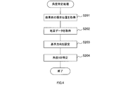
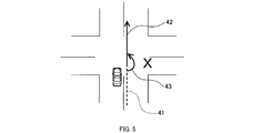
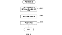
- This angle specifying process is a process of specifying an angle formed by a reference direction set based on a road around the host vehicle and the direction of the host vehicle. As will be described later, in the present embodiment, the direction of the oncoming lane is set as the reference direction.
- the angle specifying process will be specifically described with reference to the flowchart of FIG.
- the control device 9 acquires the current position of the host vehicle from the GPS receiver 4.
- the control device 9 acquires map data from the storage device 5.
- the control device 9 sets a reference direction based on the position of the host vehicle and the map data. Specifically, first, based on the road information included in the map data and the current position of the host vehicle, the host lane that is the lane in which the host vehicle is traveling is specified. And the direction of the opposite lane with respect to the own lane included in the map data is set as the reference direction.
- the opposite lane more generally, the direction of a certain lane means the direction in which the lane extends. In other words, the direction of the lane means a direction along a lane line that defines the lane (for example, a roadway center line).
- the reference direction is the direction of the oncoming lane on the road that the host vehicle was traveling just before entering the intersection until the predetermined switching timing.
- the reference direction is set to the direction of the oncoming lane on the road on which the host vehicle travels immediately after passing the intersection.
- the switching timing is the timing at which the predicted traveling direction is switched, specifically, the timing at which the operation state of the winker switch is switched from the right instruction state or the left instruction state to the straight traveling instruction state.
- the control device 9 specifies the angle X formed by the reference direction and the direction of the host vehicle. Specifically, first, the current direction of the host vehicle is calculated based on the detection result of the gyro sensor 6. Then, based on the calculated direction of the host vehicle and the set reference direction, an angle X formed by the reference direction and the direction of the host vehicle is specified.
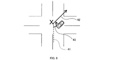
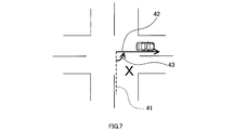
- the angle X is 180 degrees in a state where the reference direction and the direction of the host vehicle match. From this state, the angle X is set so as to decrease as the direction of the host vehicle tilts to the right with respect to the reference direction and increases as the vehicle tilts to the left. That is, as shown in FIGS. 6 and 7, the state where the direction of the host vehicle is tilted to the right with respect to the reference direction corresponds to a state where the angle X is smaller than 180 degrees. On the other hand, as shown in FIGS. 9 and 10, the state where the direction of the host vehicle is inclined to the left with respect to the reference direction corresponds to a state where the angle X is greater than 180 degrees.
- a straight line 41 indicated by a broken line indicates the direction of the oncoming lane set as the reference direction
- a straight arrow 42 indicated by a solid line indicates the direction of the host vehicle.
- a curved arrow 43 indicated by a solid line indicates the angle X.
- control device 9 When executing S204, the control device 9 ends the angle specifying process. And the control apparatus 9 will transfer to S107 of FIG. 3, after complete
- control device 9 adds (180 ⁇ X) / 90 the priority of the left front sensor 23 that monitors the left area of the host vehicle.
- control device 9 proceeds to S110 described later.
- control device 9 determines that the angle X is greater than 180 degrees in S107 described above, the control device 9 proceeds to S109.
- the control device 9 adds (X ⁇ 180) / 90 to the priority of the right front sensor 21 that monitors the right area of the host vehicle.
- the control device 9 proceeds to S110.
- the control device 9 executes control of the sensors 21 to 24 based on the priority.
- the control device 9 changes the ratio of the processing amount in the processing for detecting an obstacle based on the priority.
- the process of detecting the obstacle is executed for each of the plurality of output values output from the plurality of sensors 21 to 24.
- the control device 9 executes the same control as described in Japanese Patent No. 5327321. That is, the control device 9 changes the ratio of the processing amount by the following method.
- the control device 9 increases or decreases the cycle of processing each of the plurality of output values output from the sensors 21 to 24 according to the number of C bits in the sensors 21 to 24. Specifically, the control device 9 increases or decreases the processing cycle so that the greater the C, the shorter the cycle for processing the output value. As described above, the processing amount per unit time for the output values of the sensors 21 to 24 is changed by changing the processing cycle for the output values of the sensors 21 to 24 based on the priority.
- the control device 9 determines whether or not the ignition switch of the host vehicle is off. When it is determined that the ignition switch of the host vehicle is off, the control device 9 ends the sensor control process. On the other hand, when the control device 9 determines that the ignition switch of the host vehicle is not OFF, that is, is ON, the control device 9 proceeds to S101 described above, and executes the processing after S101 again.
- FIG. 5 shows a situation immediately after the host vehicle enters the intersection to turn right at the intersection.
- the operation state of the blinker switch is the right instruction state. Therefore, in the determination of S103 described above, it is determined that the predicted traveling direction is the right direction. As a result, the priority of the right front sensor 21 and the right rear sensor 22 is incremented by 1 in S104 described above.
- the priority of the right front sensor 21 and the right rear sensor 22 is incremented by 1 in S104 described above.
- the angle X formed by the opposite lane and the direction of the host vehicle is 180 degrees, it is determined in S107 described above that the angle X is 180 degrees or less.
- the priority of any sensor is not added. Therefore, in the situation shown in FIG. 5, the priority of the right front sensor 21 is 2, the priority of the right rear sensor 22 is 2, the priority of the left front sensor 23 is 1, and the priority of the left rear sensor 24 is 1. .
- FIG. 6 shows a situation where the host vehicle is turning right and the direction of the host vehicle is tilted to the right with respect to the direction of the oncoming lane.
- the operation state of the blinker switch is still the right instruction state. Therefore, 1 is added to the priorities of the right front sensor 21 and the right rear sensor 22 in S104 described above.
- FIG. 7 shows a situation in which the vehicle has completed a right turn and is about to leave the intersection.
- the operation state of the blinker switch is still the right instruction state. Therefore, 1 is added to the priorities of the right front sensor 21 and the right rear sensor 22 in S104 described above.
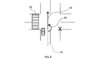
- FIG. 8 shows a situation immediately after the host vehicle enters the intersection to turn left at the intersection.
- the operation state of the blinker switch is the left instruction state. Therefore, in the determination of S103 described above, it is determined that the predicted traveling direction is the left direction. As a result, the priority of the left front sensor 23 and the left rear sensor 24 is incremented by 1 in S105 described above.
- the priority of the left front sensor 23 and the left rear sensor 24 is incremented by 1 in S105 described above.
- FIG. 9 shows a situation where the host vehicle is turning left and the direction of the host vehicle is tilted to the left with respect to the direction of the oncoming lane.
- the operation state of the blinker switch is still the left instruction state. Therefore, 1 is added to the priorities of the left front sensor 23 and the left rear sensor 24 in S105 described above.
- FIG. 10 shows a situation in which the vehicle has completed a left turn and is about to leave the intersection.
- the operation state of the blinker switch is still the left instruction state. Therefore, 1 is added to the priorities of the right front sensor 21 and the right rear sensor 22 in S105 described above.
- the control device 9 specifies an angle X formed by the direction of the oncoming lane and the direction of the host vehicle. Then, the control device 9 sets priorities of the plurality of sensors 21 to 24 according to the specified angle X. Then, the control device 9 changes the ratio of the processing amount with respect to the plurality of output values output from the plurality of sensors 21 to 24 based on the set priority.
- the priority can be changed according to the angle X. Therefore, the priority can be set appropriately according to the angle X. That is, when the host vehicle turns at an intersection or the like, the priority can be set appropriately. For this reason, it can suppress that the delay of the detection of a mobile body by the priority of a sensor being set improperly generate
- the priority of the left front sensor 23 is increased when the angle X is smaller than 180 degrees, that is, when the direction of the host vehicle is tilted to the right with respect to the direction of the oncoming lane.
- the priority of the right front sensor 21 is increased.
- the priority of the sensors 21 and 23 that monitor the area opposite to the traveling direction of the host vehicle is increased. Therefore, compared to a configuration in which the priority of only the sensor that monitors the area on the traveling direction side of the host vehicle is increased, a moving body such as an oncoming vehicle approaching the host vehicle from the side opposite to the traveling direction of the host vehicle is reduced. It can be easily detected.
- the direction of the oncoming lane is set as the reference direction. Therefore, it is possible to improve the detection accuracy of an oncoming vehicle, a bicycle traveling on a pedestrian crossing parallel to the oncoming lane, and the like. That is, the direction of the oncoming lane reflects the advancing direction of the oncoming vehicle and the advancing direction of a bicycle traveling on a pedestrian crossing parallel to the oncoming lane. Therefore, in this embodiment, a priority is set according to these traveling directions. That is, a priority level suitable for detecting oncoming vehicles, bicycles, and the like is set. Therefore, it is possible to improve the detection accuracy of an oncoming vehicle and a bicycle traveling on a pedestrian crossing parallel to the oncoming lane.
- the angle X is specified based on the current position of the host vehicle and map data. For example, when the direction of the oncoming lane is detected using a camera, the oncoming lane may not be detected when an obstacle such as a vehicle is present or when the host vehicle is traveling at night. On the other hand, according to the configuration of the present embodiment, the direction of the oncoming lane can be detected even when an obstacle such as a vehicle exists or when the host vehicle is traveling at night. For this reason, the reference direction can be detected more stably.
- control device 9 corresponds to a sensor control device
- the sensors 21 to 24 correspond to a plurality of sensors
- the left front sensor 23 corresponds to a left sensor
- the right front sensor 21 corresponds to a right sensor.
- the angle X corresponds to the direction of the vehicle specified by the specifying unit.
- S108 and S109 correspond to processing as a setting unit
- S110 corresponds to processing as an execution unit
- S201 corresponds to processing as a position acquisition unit
- S202 corresponds to processing as a map data acquisition unit.
- S204 corresponds to the processing as the specifying unit.
- the direction of the host vehicle relative to the reference direction is specified using the current position of the host vehicle and the map data.
- the second embodiment is different from the first embodiment in that the orientation of the host vehicle with respect to the reference direction is specified using the captured image of the camera 3.
- the sensor control system 1 of the second embodiment has the same hardware configuration as that of the first embodiment.
- the processing executed by the control device 9 of the second embodiment is partially different from that of the first embodiment. Specifically, only the angle specifying process executed in S106 of FIG. 3 described above is different from the first embodiment.
- the control device 9 acquires a captured image in front of the host vehicle from the camera 3.
- the control device 9 specifies an angle X formed by the reference direction and the direction of the host vehicle based on the acquired captured image. Specifically, the control device 9 performs image processing on the acquired captured image and detects the oncoming lane. Then, the control device 9 sets the detected direction of the oncoming lane as the reference direction. Further, the direction of the oncoming lane is detected as a relative direction with respect to the host vehicle in the captured image. Therefore, the detected direction of the oncoming lane is set as the reference direction, whereby the angle X formed by the reference direction and the direction of the host vehicle is specified.
- control device 9 specifies the angle X based on the captured image. Therefore, for example, the angle X can be specified with fewer errors compared to a configuration in which the angle X is specified using the GPS receiver 4 as in the first embodiment.
- S301 corresponds to processing as an image acquisition unit
- S302 corresponds to processing as a specifying unit.
- the direction of the host vehicle relative to the reference direction is specified using the current position of the host vehicle and the map data.
- the third embodiment is different from the first embodiment in that the direction of the host vehicle relative to the reference direction is specified using the operation state of the turn signal switch of the host vehicle and the steering angle of the host vehicle.
- the sensor control system 1 of the third embodiment has the same hardware configuration as that of the first embodiment.
- the processing executed by the control device 9 of the third embodiment is partially different from that of the first embodiment. Specifically, only the angle specifying process executed in S106 of FIG. 3 described above is different from the first embodiment.
- the control device 9 acquires the steering angle when the turn signal switch is operated.
- the steering angle when the turn signal switch of the host vehicle is most recently operated so that the operation state changes from the straight traveling instruction state to the right instruction state or the left instruction state is stored in the storage device 5. Yes.
- the control device 9 acquires the steering angle from the storage device 5.
- the steering angle at the time when the turn signal switch is operated is stored in the storage device 5, but the stored steering angle is not limited to this.
- the steering angle at a time slightly before and after the time when the turn signal switch is operated may be stored.
- the control device 9 acquires the current steering angle from the steering angle sensor 7.
- the control device 9 specifies the angle X based on the acquired current steering angle and the steering angle when the turn signal switch is operated.
- a change between the acquired current steering angle and the steering angle when the turn signal switch is operated is calculated. In other words, the amount of change in the steering angle up to the present is calculated based on the steering angle when the turn signal switch is operated. Then, the control device 9 specifies the change in the direction of the host vehicle according to the calculated change as the angle X.
- the turn signal switch when the turn signal switch is operated, it is estimated that the host vehicle is traveling along the reference direction. This is because when the turn signal switch is operated, the host vehicle is traveling in the host lane before the intersection, for example, and the direction of the host lane is considered to coincide with the direction of the opposite lane, that is, the reference direction. Then, it is estimated that the change in the steering angle from the time when the turn signal switch is operated corresponds to the angle X.
- the control device 9 specifies the angle X based on the change between the steering angle when the turn signal switch is operated and the current steering angle. Therefore, the angle X can be specified with a simple configuration.
- S401 corresponds to processing as the first steering angle acquisition unit
- S402 corresponds to processing as the second steering angle acquisition unit
- S403 corresponds to processing as the specifying unit.
- the sensor control process based on the premise that the road is orthogonal at the intersection is illustrated, but the sensor control process is not limited to this.
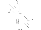
- a general sensor control process including an intersection where two roads are not orthogonal, that is, an intersection where at least one of the angle C1 and the angle C2 is not 90 degrees may be executed.
- the angle C1 here is an angle formed by the direction of the road on which the host vehicle is traveling immediately before the host vehicle enters the intersection and the direction of the road that intersects the intersection from the right.
- the angle C2 here is an angle formed by the direction of the road on which the host vehicle is traveling immediately before the host vehicle enters the intersection and the direction of the road that intersects the intersection from the left.
- the solid line 61 indicates the direction of the road on which the host vehicle is traveling immediately before the host vehicle enters the intersection.
- a broken line 62 indicates the direction of the road that intersects the intersection from the right.
- a broken line 63 indicates the direction of the road that intersects the intersection from the left.
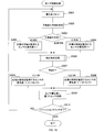
- control device 9 may execute a sensor control process of FIG. 15 described below. Steps S501 to S507 are the same as steps S101 to S107 in FIG.
- control device 9 determines in S507 that the angle X is 180 degrees or less, the control device 9 proceeds to S508.
- the control device 9 adds (180 ⁇ X) / C1 to the priority of the left front sensor 23 that monitors the left area of the host vehicle.
- the control device 9 proceeds to S510.
- step S509 the control device 9 adds (X ⁇ 180) / C2 to the priority of the right front sensor 21 that monitors the right area of the host vehicle. After executing S509, the control device 9 proceeds to S510.
- S510 and S511 are the same as S110 and S111 in FIG.
- S508 and S509 correspond to processing as a setting unit
- S510 corresponds to processing as an execution unit.
- the sensors 21 to 24 are millimeter wave radars, but the type of sensor is not limited to this.
- the sensor may be, for example, a laser radar or an image sensor such as a camera.
- the vehicle is equipped with the right front sensor 21 or the like that monitors the right front area of the vehicle, but the sensor mounted on the vehicle is not limited to this.
- the vehicle may be equipped with a right side sensor that monitors a region on the right side of the vehicle, a left side sensor that monitors a region on the left side of the vehicle, and the like.
- the predicted traveling direction is specified based on the detection result of the winker sensor 8, but the method for specifying the predicted traveling direction is not limited to this.
- the predicted traveling direction may be specified based on, for example, the driver's line of sight. Further, for example, the predicted traveling direction may be specified by estimating the position of the host vehicle on the road. Specifically, for example, when it is determined using the camera 3, the GPS receiver 4, and the storage device 5 that the host vehicle is located in the right turn lane or the left turn lane, the predicted traveling direction is the right direction or You may specify that it is the left direction.
- the switching timing of the reference direction at the intersection is not limited to those in the above embodiments.
- the reference direction may be switched when the camera 3 detects a lane marking on a road that runs immediately after the host vehicle passes through an intersection.
- the reference direction can be switched. May be.
- the direction of the oncoming lane is set as the reference direction, but the direction set as the reference direction is not limited to this.
- the direction of the own lane may be set as the reference direction.
- the direction of the pedestrian crossing 50 parallel to the own lane or the opposite lane shown in FIGS. 8 to 10 may be set as the reference direction.
- “parallel” is not limited to parallel in a strict sense, and may not be strictly parallel as long as the desired effect is achieved.
- the same effect as the effect (1d) of the first embodiment described above can be obtained. it can.
- the processing amount for the output values of the sensors 21 to 24 is changed by changing the processing cycle for the output values of the sensors 21 to 24.
- the configuration to be changed is not limited to this.
- the processing amount in a predetermined time may be changed by changing the processing amount per time while keeping the processing cycle constant.
- the ratio of the processing amount to the output values of the sensors 21 to 24 is changed based on the priority, but the control based on the priority is not limited to this.
- the ratio of the operation performance of the plurality of sensors 21 to 24 may be changed based on the priority.
- the detection accuracy of the sensors 21 to 24 may be changed as the operation performance.
- the operation of the sensors 21 to 24 may be controlled so that the higher the priority is, the higher the detection accuracy of the sensor is. According to such a configuration, the higher the priority, the higher the detection accuracy of the sensor.
- a sensor with a high priority performs monitoring with the required high detection accuracy
- a sensor with a low priority performs monitoring with a low detection accuracy with a low load on the CPU 91 and the in-vehicle LAN. Therefore, in the case where a plurality of sensors 21 to 24 are used, the load on the CPU 91 and the in-vehicle LAN can be reduced and the surroundings of the host vehicle can be appropriately adjusted as compared with the configuration in which all the sensors 21 to 24 monitor with high detection accuracy. Can be monitored.
- the control for changing the detection accuracy of the sensor is, for example, the following control. That is, for example, in FMCW radar, a beat signal generated from a transmission / reception wave is subjected to a fast Fourier transform (FFT), and a peak signal component is extracted from the processing result. Then, based on the extraction result, the distance from the target reflecting the radar wave is calculated.
- FFT fast Fourier transform
- control for changing the detection accuracy of the sensor control for changing the extraction reference when extracting peaks that can be candidates for various targets from the FFT processing result can be considered.
- control for changing the detection accuracy of the sensor control for changing the frequency range for performing the peak search, control for changing the frequency resolution of the FFT, and the like can be considered.
- control for changing the frequency resolution of the FFT control for changing the frequency resolution of the FFT, and the like can be considered.
- a part or all of the functions executed by the control device 9 may be configured by one or more ICs as hardware.
- the sensor control system 1 having the control device 9 as a constituent element, a program for causing a computer to function as the control device 9, a non-transitive semiconductor memory or the like storing the program
- the present disclosure can also be realized in various forms, such as a method of setting the priority according to the substantial storage medium and the vehicle direction with respect to the reference direction.
Abstract
In the present invention, an execution unit (S110) is configured to execute control of operation performance of multiple sensors for monitoring different areas around a vehicle and/or predetermined processing of multiple output values output from the multiple sensors. A determination unit is configured so as to determine the orientation of the vehicle with respect to a reference direction preset on the basis of roads in the vicinity of the vehicle. A setting unit (S108, S109) is configured so as to set the priorities of the multiple sensors in accordance with the orientation of the vehicle determined by the determination unit. The execution unit changes the ratios of the operation performance of the multiple sensors and/or the ratios of the processing amounts of the multiple output values on the basis of the priorities.
Description
本国際出願は、2016年10月21日に日本国特許庁に出願された日本国特許出願第2016-206888号に基づく優先権を主張するものであり、日本国特許出願第2016-206888号の全内容を参照により本国際出願に援用する。
This international application claims priority based on Japanese Patent Application No. 2016-206888 filed with the Japan Patent Office on October 21, 2016, and is based on Japanese Patent Application No. 2016-206888. The entire contents are incorporated herein by reference.
本開示は、センサ制御装置に関する。
The present disclosure relates to a sensor control device.
特許文献1には、車両の周辺の異なる領域を監視する複数のセンサの検出精度と、上記複数のセンサから出力された複数の出力値に対する処理の周期と、を制御するセンサ制御装置が開示されている。
Patent Document 1 discloses a sensor control device that controls detection accuracy of a plurality of sensors that monitor different regions around a vehicle and a processing cycle for a plurality of output values output from the plurality of sensors. ing.
このセンサ制御装置では、CPUや車載LANの負荷を低減することを目的として、複数のセンサの優先度が設定される。優先度は、車両の進行方向に基づき設定される。すなわち、まず、車両の動きやドライバの視線に基づいて車両の進行方向の判定が行われる。そして、判定の結果が車両の進行方向が右方向であることを示すときには、車両の右側の領域を監視するセンサの優先度が増加される。一方、判定の結果が車両の進行方向が左方向であることを示すときには、車両の左側の領域を監視するセンサの優先度が増加される。そして、優先度が高いセンサほど、センサ検出精度が高くなるように変更される。また、優先度が高いほど、センサの出力値に対する処理の周期が短くなるように変更される。
In this sensor control device, the priority of a plurality of sensors is set for the purpose of reducing the load on the CPU and the in-vehicle LAN. The priority is set based on the traveling direction of the vehicle. That is, first, the traveling direction of the vehicle is determined based on the movement of the vehicle and the line of sight of the driver. When the result of the determination indicates that the traveling direction of the vehicle is the right direction, the priority of the sensor that monitors the region on the right side of the vehicle is increased. On the other hand, when the determination result indicates that the traveling direction of the vehicle is the left direction, the priority of the sensor that monitors the left region of the vehicle is increased. And it changes so that a sensor detection accuracy may become high, so that a sensor with high priority. Further, the higher the priority, the shorter the processing cycle for the sensor output value.
しかしながら、発明者の詳細な検討の結果、以下の課題が見出された。すなわち、車両が進行方向を変えて曲がる場合においては、進行方向と反対側の領域を監視するセンサで移動体を検出しなければならないときがある。具体的には、例えば、車両が交差点を曲がる場合には、車両に接近する対向車両を検出する必要がある。特許文献1の構成では、車両の進行方向側の領域を監視するセンサの優先度が高くなる傾向にある。このため、車両の進行方向と反対側の領域を監視するセンサによる移動体の検出が遅れてしまうことがある。つまり、特許文献1の構成では、優先度が不適切に設定されることにより移動体の検出が遅れてしまう場合がある。
However, as a result of detailed studies by the inventors, the following problems have been found. In other words, when the vehicle turns with the traveling direction changed, it may be necessary to detect the moving body with a sensor that monitors a region opposite to the traveling direction. Specifically, for example, when a vehicle turns an intersection, it is necessary to detect an oncoming vehicle approaching the vehicle. In the configuration of Patent Document 1, the priority of the sensor that monitors the region on the traveling direction side of the vehicle tends to be high. For this reason, detection of the moving body by a sensor that monitors a region opposite to the traveling direction of the vehicle may be delayed. That is, in the configuration of Patent Document 1, detection of a moving object may be delayed due to inappropriate setting of priority.
本開示の一局面は、センサの優先度が不適切に設定されることによる移動体の検出の遅れが発生することを抑制することにある。
本開示の一態様は、実行部と、特定部と、設定部と、を備えるセンサ制御装置である。実行部は、車両の周辺の異なる領域を監視する複数のセンサの動作性能の制御、及び、複数のセンサから出力された複数の出力値のそれぞれに対する所定の処理、のうちの少なくとも一方を実行するように構成される。特定部は、車両の周辺の道路に基づき設定された基準方向に対する車両の向きを特定するように構成される。設定部は、特定部により特定された車両の向きに応じて、複数のセンサの優先度を設定するように構成される。実行部は、優先度に基づいて、複数のセンサの動作性能の割合、及び、複数の出力値に対する処理量の割合、のうちの少なくとも一方を変化させる。 One aspect of the present disclosure is to suppress the occurrence of a delay in detection of a moving object due to inappropriate setting of sensor priorities.
One aspect of the present disclosure is a sensor control device including an execution unit, a specifying unit, and a setting unit. The execution unit executes at least one of control of operation performance of the plurality of sensors that monitor different regions around the vehicle and predetermined processing for each of the plurality of output values output from the plurality of sensors. Configured as follows. The specifying unit is configured to specify a direction of the vehicle with respect to a reference direction set based on a road around the vehicle. The setting unit is configured to set priorities of the plurality of sensors according to the direction of the vehicle specified by the specifying unit. The execution unit changes at least one of the ratio of the operation performance of the plurality of sensors and the ratio of the processing amount to the plurality of output values based on the priority.
このような構成によれば、基準方向に対する車両の向きに応じて優先度を変更することができる。したがって、基準方向に対する車両の向きに応じて適切に優先度を設定することができる。つまり、例えば車両が曲がる場合において、優先度を適切に設定することができる。したがって、センサの優先度が不適切に設定されることによる移動体の検出の遅れが発生することを抑制することができる。
According to such a configuration, the priority can be changed according to the direction of the vehicle with respect to the reference direction. Therefore, the priority can be appropriately set according to the direction of the vehicle with respect to the reference direction. That is, for example, when the vehicle turns, priority can be set appropriately. Therefore, it is possible to suppress the occurrence of a delay in detection of the moving object due to inappropriate setting of the sensor priority.
なお、請求の範囲に記載した括弧内の符号は、一つの態様として後述する実施形態に記載の具体的手段との対応関係を示すものであって、本開示の技術的範囲を限定するものではない。
In addition, the code | symbol in the parenthesis described in the claim shows the correspondence with the specific means as described in embodiment mentioned later as one aspect, Comprising: It does not limit the technical scope of this indication. Absent.
以下、図面を参照しながら、本開示を実施するための形態を説明する。
[1.第1実施形態]
[1-1.構成]
図1に示すセンサ制御システム1は、車両に搭載される。センサ制御システム1は、センサ群2、カメラ3、GPS受信機4、記憶装置5、ジャイロセンサ6、操舵角センサ7、ウインカーセンサ8及び制御装置9を備える。以下では、センサ制御システム1が搭載された車両を「自車両」という。 Hereinafter, embodiments for carrying out the present disclosure will be described with reference to the drawings.
[1. First Embodiment]
[1-1. Constitution]
A sensor control system 1 shown in FIG. 1 is mounted on a vehicle. The sensor control system 1 includes asensor group 2, a camera 3, a GPS receiver 4, a storage device 5, a gyro sensor 6, a steering angle sensor 7, a winker sensor 8, and a control device 9. Hereinafter, the vehicle on which the sensor control system 1 is mounted is referred to as “own vehicle”.
[1.第1実施形態]
[1-1.構成]
図1に示すセンサ制御システム1は、車両に搭載される。センサ制御システム1は、センサ群2、カメラ3、GPS受信機4、記憶装置5、ジャイロセンサ6、操舵角センサ7、ウインカーセンサ8及び制御装置9を備える。以下では、センサ制御システム1が搭載された車両を「自車両」という。 Hereinafter, embodiments for carrying out the present disclosure will be described with reference to the drawings.
[1. First Embodiment]
[1-1. Constitution]
A sensor control system 1 shown in FIG. 1 is mounted on a vehicle. The sensor control system 1 includes a
センサ群2は、右前方センサ21、右後方センサ22、左前方センサ23及び左後方センサ24を備える。本実施形態では、センサ21~24は、ミリ波レーダである。センサ21~24は、自車両の周辺の所定領域内にミリ波帯のレーダ波を放射し、その反射波を受信することで、自車両の周辺に存在する物体の大きさ、自車両を基準とした相対位置、相対速度等を検出する。
Sensor group 2 includes a right front sensor 21, a right rear sensor 22, a left front sensor 23, and a left rear sensor 24. In the present embodiment, the sensors 21 to 24 are millimeter wave radars. The sensors 21 to 24 emit a millimeter-wave radar wave in a predetermined area around the host vehicle and receive the reflected wave, thereby making reference to the size of the object existing around the host vehicle and the host vehicle. The relative position, relative speed, etc. are detected.
図2に示すように、右前方センサ21は、自車両の右前部に設けられ、自車両の右前方の領域31を監視する。右後方センサ22は、自車両の右後部に設けられ、自車両の右後方の領域32を監視する。左前方センサ23は、自車両の左前部に設けられ、自車両の左前方の領域33を監視する。左後方センサ24は、自車両の左後部に設けられ、自車両の左後方の領域34を監視する。センサ21~24は、検出結果を制御装置9に出力する。
As shown in FIG. 2, the right front sensor 21 is provided at the right front portion of the host vehicle, and monitors a right front area 31 of the host vehicle. The right rear sensor 22 is provided in the right rear part of the host vehicle, and monitors the right rear region 32 of the host vehicle. The left front sensor 23 is provided in the left front portion of the host vehicle, and monitors a left front region 33 of the host vehicle. The left rear sensor 24 is provided at the left rear portion of the host vehicle, and monitors a left rear region 34 of the host vehicle. The sensors 21 to 24 output the detection result to the control device 9.
カメラ3は、自車両の前方を撮像する。カメラ3は、撮像画像を表すデータを制御装置9に出力する。
GPS受信機4は、GPS用の人工衛星からの送信電波を図示しないGPSアンテナを介して受信することにより自車両の現在位置を特定する。GPS受信機4は、自車両の現在位置を制御装置9に出力する。 The camera 3 images the front of the host vehicle. The camera 3 outputs data representing the captured image to the control device 9.
The GPS receiver 4 specifies the current position of the host vehicle by receiving a transmission radio wave from a GPS artificial satellite via a GPS antenna (not shown). The GPS receiver 4 outputs the current position of the host vehicle to the control device 9.
記憶装置5は、地図データを記憶する。本実施形態では、地図データには、道路情報が含まれる。道路情報には、道路のリンク及びノードのデータが含まれている。そして、道路のリンクやノードには、道路の形状、車線、交差点、横断歩道などの情報が関連付けられている。
The storage device 5 stores map data. In the present embodiment, the map data includes road information. The road information includes road link and node data. Information such as road shape, lanes, intersections, and pedestrian crossings is associated with road links and nodes.
ジャイロセンサ6は、自車両の回転角速度を検知するように構成されたセンサである。ジャイロセンサ6は、検出結果を制御装置9に出力する。
操舵角センサ7は、自車両の操舵角を検出するように構成されたセンサである。操舵角センサ7は、検出結果を制御装置9に出力する。 Thegyro sensor 6 is a sensor configured to detect the rotational angular velocity of the host vehicle. The gyro sensor 6 outputs the detection result to the control device 9.
Thesteering angle sensor 7 is a sensor configured to detect the steering angle of the host vehicle. The steering angle sensor 7 outputs the detection result to the control device 9.
操舵角センサ7は、自車両の操舵角を検出するように構成されたセンサである。操舵角センサ7は、検出結果を制御装置9に出力する。 The
The
ウインカーセンサ8は、自車両のウインカースイッチの操作状態を検出するように構成されたセンサである。以下では、指示方向が右方向であるウインカースイッチの操作状態を「右指示状態」という。また、指示方向が左方向であるウインカースイッチの操作状態を「左指示状態」という。また、指示方向が右方向及び左方向のいずれでもないウインカースイッチの操作状態を「直進指示状態」という。ウインカーセンサ8は、検出結果を制御装置9に出力する。
The turn signal sensor 8 is a sensor configured to detect the operation state of the turn signal switch of the host vehicle. Hereinafter, the operation state of the turn signal switch in which the instruction direction is the right direction is referred to as a “right instruction state”. Further, the operation state of the turn signal switch in which the instruction direction is the left direction is referred to as a “left instruction state”. In addition, an operation state of the blinker switch in which the instruction direction is neither the right direction nor the left direction is referred to as a “straight forward instruction state”. The winker sensor 8 outputs the detection result to the control device 9.
制御装置9は、CPU91、ROM92及びRAM93等を構成要素とするマイクロコンピュータを備える。CPU91がROM92等の非遷移的実体的記憶媒体に格納されているプログラムを実行する。このプログラムが実行されることで、プログラムに対応する方法が実行される。
The control device 9 includes a microcomputer including a CPU 91, a ROM 92, a RAM 93, and the like as constituent elements. The CPU 91 executes a program stored in a non-transitional physical storage medium such as the ROM 92. By executing this program, a method corresponding to the program is executed.
本実施形態では、制御装置9は、センサ群2から出力された出力値に対して、歩行者や他車両などの障害物を検出する検出処理を実行する。そして、制御装置9は、これらの障害物が検出された場合に、衝突を回避する衝突回避制御を実行する。
In the present embodiment, the control device 9 executes a detection process for detecting obstacles such as pedestrians and other vehicles with respect to the output value output from the sensor group 2. And the control apparatus 9 performs the collision avoidance control which avoids a collision, when these obstructions are detected.
また、制御装置9は、後述する図3及び図4に示すセンサ制御処理を実行する。このセンサ制御処理では、各センサ21~24の優先度が設定される。そして、設定された優先度に基づき、各センサ21~24から出力される出力値に対する検出処理の処理量の割合が変更される。
Further, the control device 9 executes a sensor control process shown in FIGS. 3 and 4 to be described later. In this sensor control process, priorities of the sensors 21 to 24 are set. Based on the set priority, the ratio of the processing amount of the detection processing to the output values output from the sensors 21 to 24 is changed.
[1-2.処理]
次に、制御装置9が実行するセンサ制御処理を図3及び図4を用いて説明する。センサ制御処理は、自車両のイグニッションスイッチがオンにされることにより開始される。 [1-2. processing]
Next, sensor control processing executed by the control device 9 will be described with reference to FIGS. The sensor control process is started when the ignition switch of the host vehicle is turned on.
S101で、制御装置9は、すべてのセンサ21~24の優先度を初期値にリセットする。本実施形態では、初期値は1である。
S102で、制御装置9は、現時点よりも後の所定の時点における自車両の進行方向である予測進行方向を特定する。ここでいう現時点よりも後の所定の時点とは、現時点において自車両が交差点の手前に位置している場合において、自車両が交差点を曲がっている途中の時点となるように設定される。 In S101, the control device 9 resets the priorities of all thesensors 21 to 24 to the initial values. In this embodiment, the initial value is 1.
In S102, the control device 9 specifies a predicted traveling direction that is a traveling direction of the host vehicle at a predetermined time point after the current time point. The predetermined time point after the current time point is set to be a point in time when the own vehicle is turning the intersection when the own vehicle is located before the intersection at the current time point.
S102で、制御装置9は、現時点よりも後の所定の時点における自車両の進行方向である予測進行方向を特定する。ここでいう現時点よりも後の所定の時点とは、現時点において自車両が交差点の手前に位置している場合において、自車両が交差点を曲がっている途中の時点となるように設定される。 In S101, the control device 9 resets the priorities of all the
In S102, the control device 9 specifies a predicted traveling direction that is a traveling direction of the host vehicle at a predetermined time point after the current time point. The predetermined time point after the current time point is set to be a point in time when the own vehicle is turning the intersection when the own vehicle is located before the intersection at the current time point.
S102では、制御装置9は、ウインカーセンサ8の検出結果に基づき、予測進行方向を特定する。具体的には、S102の実行時にウインカースイッチの操作状態が直進指示状態である場合には、予測進行方向は直進方向であると特定される。また、S102の実行時にウインカースイッチの操作状態が右指示状態である場合には、予測進行方向は右方向であると特定される。また、S102の実行時にウインカースイッチの操作状態が左指示状態である場合には、予測進行方向は左方向であると特定される。
In S102, the control device 9 specifies the predicted traveling direction based on the detection result of the winker sensor 8. Specifically, when the operation state of the winker switch is the straight traveling instruction state at the time of executing S102, the predicted traveling direction is specified as the straight traveling direction. Further, when the operation state of the winker switch is the right instruction state when S102 is executed, the predicted traveling direction is specified as the right direction. Further, when the operation state of the winker switch is the left instruction state when S102 is executed, the predicted traveling direction is specified as the left direction.
S103で、制御装置9は、予測進行方向が直進方向、左方向及び右方向のうちのいずれであるのかを判定する。制御装置9は、予測進行方向が直進方向であると判定した場合には、後述するS106に移行する。一方、制御装置9は、予測進行方向が右方向であると判定した場合には、S104に移行する。
In S103, the control device 9 determines which of the straight traveling direction, the left direction, and the right direction is the predicted traveling direction. When determining that the predicted traveling direction is the straight traveling direction, the control device 9 proceeds to S106 described later. On the other hand, when the control device 9 determines that the predicted traveling direction is the right direction, the control device 9 proceeds to S104.
S104で、制御装置9は、自車両の右側の領域を監視する右前方センサ21及び右後方センサ22の優先度を1加算する。制御装置9は、S104を実行すると、後述するS106に移行する。
In S104, the control device 9 adds 1 to the priority of the right front sensor 21 and the right rear sensor 22 that monitor the right area of the host vehicle. When executing S104, the control device 9 proceeds to S106 described later.
一方、制御装置9は、前述したS103で予測進行方向が左方向であると判定した場合には、S105に移行する。
S105で、制御装置9は、自車両の左側の領域を監視する左前方センサ23及び左後方センサ24の優先度を1加算する。制御装置9は、S105を実行すると、S106に移行する。 On the other hand, when the control device 9 determines in S103 described above that the predicted traveling direction is the left direction, the control device 9 proceeds to S105.
In S105, the control device 9 adds 1 to the priority of theleft front sensor 23 and the left rear sensor 24 that monitor the left region of the host vehicle. When executing S105, the control device 9 proceeds to S106.
S105で、制御装置9は、自車両の左側の領域を監視する左前方センサ23及び左後方センサ24の優先度を1加算する。制御装置9は、S105を実行すると、S106に移行する。 On the other hand, when the control device 9 determines in S103 described above that the predicted traveling direction is the left direction, the control device 9 proceeds to S105.
In S105, the control device 9 adds 1 to the priority of the
S106で、制御装置9は、角度特定処理を実行する。この角度特定処理は、自車両の周辺の道路に基づき設定された基準方向と、自車両の向きと、がなす角度を特定する処理である。後述するように、本実施形態では、対向車線の方向が基準方向として設定される。以下、角度特定処理について、図4のフローチャートを用いて具体的に説明する。
In S106, the control device 9 executes an angle specifying process. This angle specifying process is a process of specifying an angle formed by a reference direction set based on a road around the host vehicle and the direction of the host vehicle. As will be described later, in the present embodiment, the direction of the oncoming lane is set as the reference direction. Hereinafter, the angle specifying process will be specifically described with reference to the flowchart of FIG.
S201で、制御装置9は、GPS受信機4から自車両の現在位置を取得する。
S202で、制御装置9は、記憶装置5から地図データを取得する。
S203で、制御装置9は、自車両の位置と地図データとに基づいて、基準方向を設定する。具体的には、まず、地図データに含まれる道路情報と、自車両の現在位置と、に基づき、自車両が走行している車線である自車線が特定される。そして、地図データに含まれる、自車線に対する対向車線の方向が、基準方向として設定される。なお、ここでいう対向車線、より一般には、ある車線の方向とは、その車線が延びる方向を意味する。換言すれば、車線の方向とは、その車線を規定する区画線(例えば車道中央線など)に沿う方向を意味する。 In S <b> 201, the control device 9 acquires the current position of the host vehicle from the GPS receiver 4.
In S <b> 202, the control device 9 acquires map data from thestorage device 5.
In S203, the control device 9 sets a reference direction based on the position of the host vehicle and the map data. Specifically, first, based on the road information included in the map data and the current position of the host vehicle, the host lane that is the lane in which the host vehicle is traveling is specified. And the direction of the opposite lane with respect to the own lane included in the map data is set as the reference direction. Here, the opposite lane, more generally, the direction of a certain lane means the direction in which the lane extends. In other words, the direction of the lane means a direction along a lane line that defines the lane (for example, a roadway center line).
S202で、制御装置9は、記憶装置5から地図データを取得する。
S203で、制御装置9は、自車両の位置と地図データとに基づいて、基準方向を設定する。具体的には、まず、地図データに含まれる道路情報と、自車両の現在位置と、に基づき、自車両が走行している車線である自車線が特定される。そして、地図データに含まれる、自車線に対する対向車線の方向が、基準方向として設定される。なお、ここでいう対向車線、より一般には、ある車線の方向とは、その車線が延びる方向を意味する。換言すれば、車線の方向とは、その車線を規定する区画線(例えば車道中央線など)に沿う方向を意味する。 In S <b> 201, the control device 9 acquires the current position of the host vehicle from the GPS receiver 4.
In S <b> 202, the control device 9 acquires map data from the
In S203, the control device 9 sets a reference direction based on the position of the host vehicle and the map data. Specifically, first, based on the road information included in the map data and the current position of the host vehicle, the host lane that is the lane in which the host vehicle is traveling is specified. And the direction of the opposite lane with respect to the own lane included in the map data is set as the reference direction. Here, the opposite lane, more generally, the direction of a certain lane means the direction in which the lane extends. In other words, the direction of the lane means a direction along a lane line that defines the lane (for example, a roadway center line).
また、自車両が交差点を右左折する場合など、対向車線が切り替わる場合には、所定の切替タイミングまで、基準方向は、自車両が交差点に進入する直前に走行していた道路における対向車線の方向に設定される。そして、切替タイミングで、基準方向は、自車両が交差点を抜けた直後に走行する道路における対向車線の方向に設定される。本実施形態では、切替タイミングは、予測進行方向が切り替わるタイミング、具体的には、ウインカースイッチの操作状態が、右指示状態又は左指示状態から直進指示状態に切り替えられたタイミングである。
Also, when the oncoming lane is switched, such as when the host vehicle turns right or left at the intersection, the reference direction is the direction of the oncoming lane on the road that the host vehicle was traveling just before entering the intersection until the predetermined switching timing. Set to At the switching timing, the reference direction is set to the direction of the oncoming lane on the road on which the host vehicle travels immediately after passing the intersection. In the present embodiment, the switching timing is the timing at which the predicted traveling direction is switched, specifically, the timing at which the operation state of the winker switch is switched from the right instruction state or the left instruction state to the straight traveling instruction state.
S204で、制御装置9は、基準方向と自車両の向きとがなす角度Xを特定する。具体的には、まず、ジャイロセンサ6の検出結果に基づき、現在の自車両の向きが算出される。そして、算出された自車両の向きと設定された基準方向とに基づいて、基準方向と自車両の向きとがなす角度Xが特定される。
In S204, the control device 9 specifies the angle X formed by the reference direction and the direction of the host vehicle. Specifically, first, the current direction of the host vehicle is calculated based on the detection result of the gyro sensor 6. Then, based on the calculated direction of the host vehicle and the set reference direction, an angle X formed by the reference direction and the direction of the host vehicle is specified.
本実施形態では、角度Xは、基準方向と自車両の向きとが一致している状態で180度になる。そして、角度Xは、この状態から、自車両の向きが基準方向に対して右に傾くほど小さくなり、左に傾くほど大きくなるように設定される。つまり、図6及び図7に示すように基準方向に対して自車両の向きが右側に傾いている状態は、角度Xが180度よりも小さい状態に対応する。一方、図9及び図10に示すように基準方向に対して自車両の向きが左側に傾いている状態は、角度Xが180度よりも大きい状態に対応する。なお、図5~図10では、破線で示す直線41は、基準方向として設定された対向車線の方向を示しており、実線で示す直線状の矢印42は、自車両の向きを示している。また、実線で示す曲線状の矢印43は角度Xを示している。
In the present embodiment, the angle X is 180 degrees in a state where the reference direction and the direction of the host vehicle match. From this state, the angle X is set so as to decrease as the direction of the host vehicle tilts to the right with respect to the reference direction and increases as the vehicle tilts to the left. That is, as shown in FIGS. 6 and 7, the state where the direction of the host vehicle is tilted to the right with respect to the reference direction corresponds to a state where the angle X is smaller than 180 degrees. On the other hand, as shown in FIGS. 9 and 10, the state where the direction of the host vehicle is inclined to the left with respect to the reference direction corresponds to a state where the angle X is greater than 180 degrees. 5 to 10, a straight line 41 indicated by a broken line indicates the direction of the oncoming lane set as the reference direction, and a straight arrow 42 indicated by a solid line indicates the direction of the host vehicle. A curved arrow 43 indicated by a solid line indicates the angle X.
制御装置9は、S204を実行すると、角度特定処理を終了する。そして、制御装置9は、角度特定処理を終了すると、図3のS107に移行する。
S107で、制御装置9は、特定した角度Xが180度以下であるか180度よりも大きいかを判定する。制御装置9は、角度Xが180度以下であると判定した場合に、S108に移行する。 When executing S204, the control device 9 ends the angle specifying process. And the control apparatus 9 will transfer to S107 of FIG. 3, after complete | finishing an angle specific process.
In S107, the control device 9 determines whether the specified angle X is 180 degrees or less or larger than 180 degrees. When the control device 9 determines that the angle X is 180 degrees or less, the control device 9 proceeds to S108.
S108で、制御装置9は、自車両の左側の領域を監視する左前方センサ23の優先度を(180-X)/90加算する。制御装置9は、S108を実行すると、後述するS110に移行する。
In S108, the control device 9 adds (180−X) / 90 the priority of the left front sensor 23 that monitors the left area of the host vehicle. When executing S108, the control device 9 proceeds to S110 described later.
一方、制御装置9は、前述したS107で、角度Xが180度よりも大きいと判定した場合に、S109に移行する。
S109で、制御装置9は、自車両の右側の領域を監視する右前方センサ21の優先度を(X-180)/90加算する。制御装置9は、S109を実行すると、S110に移行する。 On the other hand, when the control device 9 determines that the angle X is greater than 180 degrees in S107 described above, the control device 9 proceeds to S109.
In S109, the control device 9 adds (X−180) / 90 to the priority of the rightfront sensor 21 that monitors the right area of the host vehicle. When executing S109, the control device 9 proceeds to S110.
S109で、制御装置9は、自車両の右側の領域を監視する右前方センサ21の優先度を(X-180)/90加算する。制御装置9は、S109を実行すると、S110に移行する。 On the other hand, when the control device 9 determines that the angle X is greater than 180 degrees in S107 described above, the control device 9 proceeds to S109.
In S109, the control device 9 adds (X−180) / 90 to the priority of the right
S110で、制御装置9は、優先度に基づくセンサ21~24の制御を実行する。本実施形態では、制御装置9は、優先度に基づいて、障害物を検出する処理における処理量の割合を変更する。障害物を検出する処理は、複数のセンサ21~24から出力された複数の出力値のそれぞれに対して実行される。具体的には、制御装置9は、特許第5327321号公報の記載と同様の制御を実行する。すなわち、制御装置9は、以下の方法で処理量の割合を変更する。
In S110, the control device 9 executes control of the sensors 21 to 24 based on the priority. In the present embodiment, the control device 9 changes the ratio of the processing amount in the processing for detecting an obstacle based on the priority. The process of detecting the obstacle is executed for each of the plurality of output values output from the plurality of sensors 21 to 24. Specifically, the control device 9 executes the same control as described in Japanese Patent No. 5327321. That is, the control device 9 changes the ratio of the processing amount by the following method.
まず、制御装置9は、センサ21~24の優先度の合計値Aを算出する。例えば、右前方センサ21の優先度=2、右後方センサ22の優先度=2、左前方センサ23の優先度=1、左後方センサ24の優先度=1である場合、優先度の合計値AはA=2+2+1+1=6となる。
First, the control device 9 calculates the total value A of the priorities of the sensors 21 to 24. For example, when the priority of the right front sensor 21 is 2, the priority of the right rear sensor 22 is 2, the priority of the left front sensor 23 is 1, and the priority of the left rear sensor 24 is 1, the total value of the priorities. A becomes A = 2 + 2 + 1 + 1 = 6.
続いて、制御装置9は、B={(障害物の検出処理に割り当てられたビット数)/A}を算出する。例えば、障害物の検出処理に割り当てられたビット数が単位時間当たり24ビットであるとすると、上記の例においては、A=6であるため、B=24/6=4となる。
Subsequently, the control device 9 calculates B = {(the number of bits allocated to the obstacle detection process) / A}. For example, if the number of bits allocated to the obstacle detection process is 24 bits per unit time, A = 6 in the above example, so B = 24/6 = 4.
続いて、制御装置9は、C={(各センサ21~24の優先度)×B}を算出する。上記の例においては、右前方センサ21のC=2×4=8、右後方センサ22のC=2×4=8、左前方センサ23のC=1×4=4、左後方センサ24のC=1×4=4となる。
Subsequently, the control device 9 calculates C = {(priority of each sensor 21 to 24) × B}. In the above example, C = 2 × 4 = 8 for the right front sensor 21, C = 2 × 4 = 8 for the right rear sensor 22, C = 1 × 4 = 4 for the left front sensor 23, C = 1 × 4 = 4.
続いて、制御装置9は、各センサ21~24から出力された複数の出力値のそれぞれを処理する周期を各センサ21~24におけるCのビット数に応じて増減する。具体的には、制御装置9は、Cが大きいほど出力値を処理する周期が短くなるように、処理の周期を増減する。このように、優先度に基づいて、各センサ21~24の出力値に対する処理の周期を変更することで、各センサ21~24の出力値に対する単位時間当たり処理量が変化される。
Subsequently, the control device 9 increases or decreases the cycle of processing each of the plurality of output values output from the sensors 21 to 24 according to the number of C bits in the sensors 21 to 24. Specifically, the control device 9 increases or decreases the processing cycle so that the greater the C, the shorter the cycle for processing the output value. As described above, the processing amount per unit time for the output values of the sensors 21 to 24 is changed by changing the processing cycle for the output values of the sensors 21 to 24 based on the priority.
S111で、制御装置9は、自車両のイグニッションスイッチがオフであるか否かを判定する。制御装置9は、自車両のイグニッションスイッチがオフであると判定した場合に、センサ制御処理を終了する。一方、制御装置9は、自車両のイグニッションスイッチがオフでない、つまり、オンであると判定した場合に、前述したS101に移行し、S101以降の処理を再度実行する。
In S111, the control device 9 determines whether or not the ignition switch of the host vehicle is off. When it is determined that the ignition switch of the host vehicle is off, the control device 9 ends the sensor control process. On the other hand, when the control device 9 determines that the ignition switch of the host vehicle is not OFF, that is, is ON, the control device 9 proceeds to S101 described above, and executes the processing after S101 again.
[1-3.具体例]
次に、前述したセンサ制御処理の結果、各センサ21~24の優先度がどのように設定されるのかを、図5~図10に示す具体例を用いて説明する。 [1-3. Concrete example]
Next, how the priorities of thesensors 21 to 24 are set as a result of the sensor control process described above will be described with reference to specific examples shown in FIGS.
次に、前述したセンサ制御処理の結果、各センサ21~24の優先度がどのように設定されるのかを、図5~図10に示す具体例を用いて説明する。 [1-3. Concrete example]
Next, how the priorities of the
[1-3-1.右折時]
まず、図5~図7を用いて、自車両が交差点を右折する場合の優先度の設定について説明する。 [1-3-1. When turning right]
First, the setting of the priority when the host vehicle turns right at the intersection will be described with reference to FIGS.
まず、図5~図7を用いて、自車両が交差点を右折する場合の優先度の設定について説明する。 [1-3-1. When turning right]
First, the setting of the priority when the host vehicle turns right at the intersection will be described with reference to FIGS.
図5には、自車両が交差点に右折しようとして交差点に進入した直後の状況が示されている。この状況では、ウインカースイッチの操作状態は右指示状態である。したがって、前述したS103の判定において、予測進行方向は右方向であると判定される。その結果、前述したS104で、右前方センサ21及び右後方センサ22の優先度が1加算される。一方、対向車線と自車両の向きとがなす角度Xは180度であるため、前述したS107で、角度Xは180度以下であると判定される。その結果、前述したS108で、自車両の左側の領域を監視する左前方センサ23の優先度が(180-180)/90=0加算される。つまり、いずれのセンサの優先度も加算されない。したがって、図5に示す状況では、右前方センサ21の優先度=2、右後方センサ22の優先度=2、左前方センサ23の優先度=1、左後方センサ24の優先度=1となる。
FIG. 5 shows a situation immediately after the host vehicle enters the intersection to turn right at the intersection. In this situation, the operation state of the blinker switch is the right instruction state. Therefore, in the determination of S103 described above, it is determined that the predicted traveling direction is the right direction. As a result, the priority of the right front sensor 21 and the right rear sensor 22 is incremented by 1 in S104 described above. On the other hand, since the angle X formed by the opposite lane and the direction of the host vehicle is 180 degrees, it is determined in S107 described above that the angle X is 180 degrees or less. As a result, in S108 described above, the priority of the left front sensor 23 for monitoring the left area of the host vehicle is added by (180-180) / 90 = 0. That is, the priority of any sensor is not added. Therefore, in the situation shown in FIG. 5, the priority of the right front sensor 21 is 2, the priority of the right rear sensor 22 is 2, the priority of the left front sensor 23 is 1, and the priority of the left rear sensor 24 is 1. .
続く図6には、自車両が右折しており、自車両の向きが対向車線の方向に対して右側に傾いている状況が示されている。この状況では、依然として、ウインカースイッチの操作状態は右指示状態である。したがって、前述したS104で、右前方センサ21及び右後方センサ22の優先度が1加算される。一方、対向車線と自車両の向きとがなす角度Xは135度であるため、前述したS108で、自車両の左側の領域を監視する左前方センサ23の優先度が(180-135)/90=1/2加算される。したがって、図6に示す状況では、右前方センサ21の優先度=2、右後方センサ22の優先度=2、左前方センサ23の優先度=3/2、左後方センサ24の優先度=1となる。なお、このように、左前方センサ23の優先度が加算されるのは、自車両の左側から接近して来る対向車両を検出するためである。
Next, FIG. 6 shows a situation where the host vehicle is turning right and the direction of the host vehicle is tilted to the right with respect to the direction of the oncoming lane. In this situation, the operation state of the blinker switch is still the right instruction state. Therefore, 1 is added to the priorities of the right front sensor 21 and the right rear sensor 22 in S104 described above. On the other hand, since the angle X formed by the opposite lane and the direction of the host vehicle is 135 degrees, the priority of the left front sensor 23 for monitoring the left area of the host vehicle is (180-135) / 90 in S108 described above. = 1/2 is added. Therefore, in the situation shown in FIG. 6, the priority of the right front sensor 21 = 2, the priority of the right rear sensor 22 = 2, the priority of the left front sensor 23 = 3/2, and the priority of the left rear sensor 24 = 1. It becomes. In this way, the priority of the left front sensor 23 is added in order to detect an oncoming vehicle approaching from the left side of the host vehicle.
続く図7には、自車両が右折を完了し、交差点から出ようとしている状況が示されている。この状況では、ウインカースイッチの操作状態はまだ右指示状態である。したがって、前述したS104で、右前方センサ21及び右後方センサ22の優先度が1加算される。一方、対向車線と自車両の向きとがなす角度Xは90度であるため、前述したS108で、自車両の左側の領域を監視する左前方センサ23の優先度が(180-90)/90=1加算される。したがって、図7に示す状況では、右前方センサ21の優先度=2、右後方センサ22の優先度=2、左前方センサ23の優先度=2、左後方センサ24の優先度=1となる。
Next, FIG. 7 shows a situation in which the vehicle has completed a right turn and is about to leave the intersection. In this situation, the operation state of the blinker switch is still the right instruction state. Therefore, 1 is added to the priorities of the right front sensor 21 and the right rear sensor 22 in S104 described above. On the other hand, since the angle X formed by the opposite lane and the direction of the host vehicle is 90 degrees, the priority of the left front sensor 23 for monitoring the left area of the host vehicle is (180-90) / 90 in S108 described above. = 1 is added. Therefore, in the situation shown in FIG. 7, the priority of the right front sensor 21 = 2, the priority of the right rear sensor 22 = 2, the priority of the left front sensor 23 = 2, and the priority of the left rear sensor 24 = 1. .
[1-3-1.左折時]
次に、図8~図10を用いて、自車両が交差点を左折する場合の優先度の設定について説明する。 [1-3-1. When turning left]
Next, with reference to FIGS. 8 to 10, the setting of priority when the host vehicle makes a left turn at an intersection will be described.
次に、図8~図10を用いて、自車両が交差点を左折する場合の優先度の設定について説明する。 [1-3-1. When turning left]
Next, with reference to FIGS. 8 to 10, the setting of priority when the host vehicle makes a left turn at an intersection will be described.
図8には、自車両が交差点に左折しようとして交差点に進入した直後の状況が示されている。この状況では、ウインカースイッチの操作状態は左指示状態である。したがって、前述したS103の判定において、予測進行方向は左方向であると判定される。その結果、前述したS105で、左前方センサ23及び左後方センサ24の優先度が1加算される。一方、対向車線と自車両の向きとがなす角度Xは180度であるため、前述したS107で、角度Xは180度以下であると判定される。その結果、前述したS108で、自車両の左側の領域を監視する左前方センサ23の優先度が(180-180)/90=0加算される。つまり、いずれのセンサの優先度も加算されない。したがって、図8に示す状況では、右前方センサ21の優先度=1、右後方センサ22の優先度=1、左前方センサ23の優先度=2、左後方センサ24の優先度=2となる。
FIG. 8 shows a situation immediately after the host vehicle enters the intersection to turn left at the intersection. In this situation, the operation state of the blinker switch is the left instruction state. Therefore, in the determination of S103 described above, it is determined that the predicted traveling direction is the left direction. As a result, the priority of the left front sensor 23 and the left rear sensor 24 is incremented by 1 in S105 described above. On the other hand, since the angle X formed by the opposite lane and the direction of the host vehicle is 180 degrees, it is determined in S107 described above that the angle X is 180 degrees or less. As a result, in S108 described above, the priority of the left front sensor 23 for monitoring the left area of the host vehicle is added by (180-180) / 90 = 0. That is, the priority of any sensor is not added. Therefore, in the situation shown in FIG. 8, the priority of the right front sensor 21 = 1, the priority of the right rear sensor 22 = 1, the priority of the left front sensor 23 = 2, and the priority of the left rear sensor 24 = 2. .
続く図9には、自車両が左折しており、自車両の向きが対向車線の方向に対して左側に傾いている状況が示されている。この場合、依然として、ウインカースイッチの操作状態は左指示状態である。したがって、前述したS105で、左前方センサ23及び左後方センサ24の優先度が1加算される。一方、対向車線と自車両の向きとがなす角度Xは225度であるため、前述したS109で、自車両の右側の領域を監視する右前方センサ21の優先度が(225-180)/90=1/2加算される。したがって、図9に示す状況では、右前方センサ21の優先度=3/2、右後方センサ22の優先度=1、左前方センサ23の優先度=2、左後方センサ24の優先度=2となる。なお、このように、右前方センサ21の優先度が加算されるのは、右側から自車両に接近して来る、横断歩道50を走行している自転車等を検出するためである。
Next, FIG. 9 shows a situation where the host vehicle is turning left and the direction of the host vehicle is tilted to the left with respect to the direction of the oncoming lane. In this case, the operation state of the blinker switch is still the left instruction state. Therefore, 1 is added to the priorities of the left front sensor 23 and the left rear sensor 24 in S105 described above. On the other hand, since the angle X formed by the opposite lane and the direction of the host vehicle is 225 degrees, the priority of the right front sensor 21 that monitors the right area of the host vehicle is (225-180) / 90 in S109 described above. = 1/2 is added. Therefore, in the situation shown in FIG. 9, the priority of the right front sensor 21 = 3/2, the priority of the right rear sensor 22 = 1, the priority of the left front sensor 23 = 2, and the priority of the left rear sensor 24 = 2. It becomes. In this way, the priority of the right front sensor 21 is added in order to detect a bicycle or the like traveling on the pedestrian crossing 50 that approaches the host vehicle from the right side.
続く図10には、自車両が左折を完了し、交差点から出ようとしている状況が示されている。この状況では、ウインカースイッチの操作状態はまだ左指示状態である。したがって、前述したS105で、右前方センサ21及び右後方センサ22の優先度が1加算される。一方、対向車線と自車両の向きとがなす角度Xは270度であるため、前述したS109で、自車両の右側の領域を監視する右前方センサ21の優先度が(270-180)/90=1加算される。したがって、図10に示す状況では、右前方センサ21の優先度=2、右後方センサ22の優先度=1、左前方センサ23の優先度=2、左後方センサ24の優先度=2となる。
Next, FIG. 10 shows a situation in which the vehicle has completed a left turn and is about to leave the intersection. In this situation, the operation state of the blinker switch is still the left instruction state. Therefore, 1 is added to the priorities of the right front sensor 21 and the right rear sensor 22 in S105 described above. On the other hand, since the angle X formed by the opposite lane and the direction of the host vehicle is 270 degrees, the priority of the right front sensor 21 that monitors the right area of the host vehicle is (270-180) / 90 in S109 described above. = 1 is added. Therefore, in the situation shown in FIG. 10, the priority of the right front sensor 21 is 2, the priority of the right rear sensor 22 is 1, the priority of the left front sensor 23 is 2, and the priority of the left rear sensor 24 is 2. .
[1-4.効果]
以上詳述した第1実施形態によれば、以下の効果が得られる。
(1a)本実施形態では、制御装置9は、対向車線の方向と自車両の向きとがなす角度Xを特定する。そして、制御装置9は、特定された角度Xに応じて、複数のセンサ21~24の優先度を設定する。そして、制御装置9は、設定された優先度に基づいて、複数のセンサ21~24から出力された複数の出力値に対する処理量の割合を変化させる。 [1-4. effect]
According to the first embodiment described in detail above, the following effects can be obtained.
(1a) In this embodiment, the control device 9 specifies an angle X formed by the direction of the oncoming lane and the direction of the host vehicle. Then, the control device 9 sets priorities of the plurality ofsensors 21 to 24 according to the specified angle X. Then, the control device 9 changes the ratio of the processing amount with respect to the plurality of output values output from the plurality of sensors 21 to 24 based on the set priority.
以上詳述した第1実施形態によれば、以下の効果が得られる。
(1a)本実施形態では、制御装置9は、対向車線の方向と自車両の向きとがなす角度Xを特定する。そして、制御装置9は、特定された角度Xに応じて、複数のセンサ21~24の優先度を設定する。そして、制御装置9は、設定された優先度に基づいて、複数のセンサ21~24から出力された複数の出力値に対する処理量の割合を変化させる。 [1-4. effect]
According to the first embodiment described in detail above, the following effects can be obtained.
(1a) In this embodiment, the control device 9 specifies an angle X formed by the direction of the oncoming lane and the direction of the host vehicle. Then, the control device 9 sets priorities of the plurality of
このように、本実施形態では、角度Xに応じて優先度を変更することができる。したがって、角度Xに応じて適切に優先度を設定することができる。つまり、自車両が交差点などを曲がる場合において、優先度を適切に設定することができる。このため、センサの優先度が不適切に設定されることによる移動体の検出の遅れが発生することを抑制することができる。
Thus, in this embodiment, the priority can be changed according to the angle X. Therefore, the priority can be set appropriately according to the angle X. That is, when the host vehicle turns at an intersection or the like, the priority can be set appropriately. For this reason, it can suppress that the delay of the detection of a mobile body by the priority of a sensor being set improperly generate | occur | produces.
(1b)本実施形態では、優先度が高いほど、センサの出力値に対する処理の周期が短くなるように変更される。このため、優先度が高いほど、センサが出力した出力値に対する単位時間当たりの処理量、具体的には処理頻度が大きくなるように変更される。したがって、優先度が高いセンサの出力値は、必要な大きな処理頻度で処理され、優先順位が低いセンサの出力値は、CPU91や車載LANの負荷が少ない処理頻度で処理される。このため、複数のセンサ21~24を用いる場合において、すべてのセンサ21~24の出力値を高頻度で処理する構成と比較して、CPU91や車載LANの負荷を低減しつつ、自車両の周辺を適切に監視することができる。
(1b) In this embodiment, the higher the priority, the shorter the processing cycle for the sensor output value. For this reason, the higher the priority, the larger the processing amount per unit time for the output value output from the sensor, specifically, the processing frequency is changed. Therefore, the output value of a sensor with a high priority is processed with a necessary large processing frequency, and the output value of a sensor with a low priority is processed with a processing frequency with a low load on the CPU 91 and the in-vehicle LAN. Therefore, in the case of using a plurality of sensors 21 to 24, the load on the CPU 91 and the in-vehicle LAN is reduced while the output values of all the sensors 21 to 24 are processed at a high frequency. Can be monitored appropriately.
また、このようにCPUの負荷が低減されるため、演算能力の小さいCPUを用いることができる。したがって、CPUのコストを抑制することができる。また、CPUを備えるチップ等のサイズを小さくし、スペースを節約することができる。
In addition, since the load on the CPU is reduced in this way, it is possible to use a CPU with a small computing capacity. Therefore, the cost of the CPU can be suppressed. In addition, the size of a chip or the like equipped with a CPU can be reduced to save space.
(1c)本実施形態では、角度Xが180度よりも小さい場合、つまり、対向車線の方向に対して自車両の向きが右側に傾いている場合に、左前方センサ23の優先度が増加される。一方、角度Xが180度よりも大きい場合、つまり、対向車線の方向に対して自車両の向きが左側に傾いている場合に、右前方センサ21の優先度が増加される。
(1c) In this embodiment, the priority of the left front sensor 23 is increased when the angle X is smaller than 180 degrees, that is, when the direction of the host vehicle is tilted to the right with respect to the direction of the oncoming lane. The On the other hand, when the angle X is greater than 180 degrees, that is, when the direction of the host vehicle is tilted to the left with respect to the direction of the oncoming lane, the priority of the right front sensor 21 is increased.
したがって、自車両が曲がる場合において、自車両の進行方向と反対側の領域を監視するセンサ21,23の優先度が増加される。よって、自車両の進行方向側の領域を監視するセンサのみの優先度を増加させる構成と比較して、自車両の進行方向と反対側から自車両に接近して来る対向車両等の移動体を検出しやすくすることができる。
Therefore, when the host vehicle turns, the priority of the sensors 21 and 23 that monitor the area opposite to the traveling direction of the host vehicle is increased. Therefore, compared to a configuration in which the priority of only the sensor that monitors the area on the traveling direction side of the host vehicle is increased, a moving body such as an oncoming vehicle approaching the host vehicle from the side opposite to the traveling direction of the host vehicle is reduced. It can be easily detected.
(1d)本実施形態では、対向車線の方向が基準方向として設定される。したがって、対向車両、対向車線に平行な横断歩道を走行する自転車等の検出精度を向上させることができる。すなわち、対向車線の方向は、対向車両の進行方向、及び、対向車線に平行な横断歩道を走行する自転車等の進行方向を反映する。したがって、本実施形態では、これらの進行方向に応じて優先度が設定される。つまり、対向車両、自転車等の検出に適した優先度の設定がなされる。よって、対向車両、対向車線に平行な横断歩道を走行する自転車等の検出精度を向上させることができる。
(1d) In this embodiment, the direction of the oncoming lane is set as the reference direction. Therefore, it is possible to improve the detection accuracy of an oncoming vehicle, a bicycle traveling on a pedestrian crossing parallel to the oncoming lane, and the like. That is, the direction of the oncoming lane reflects the advancing direction of the oncoming vehicle and the advancing direction of a bicycle traveling on a pedestrian crossing parallel to the oncoming lane. Therefore, in this embodiment, a priority is set according to these traveling directions. That is, a priority level suitable for detecting oncoming vehicles, bicycles, and the like is set. Therefore, it is possible to improve the detection accuracy of an oncoming vehicle and a bicycle traveling on a pedestrian crossing parallel to the oncoming lane.
(1e)本実施形態では、自車両の現在位置及び地図データに基づいて、角度Xが特定される。例えば、カメラを用いて対向車線の方向を検出する場合、車両等の障害物が存在するときや自車両が夜間を走行しているときには、対向車線が検出されない場合がある。これに対して、本実施形態の構成によれば、車両等の障害物が存在するときや自車両が夜間を走行しているときであっても、対向車線の方向を検出することができる。このため、より安定的に基準方向を検出することができる。
(1e) In this embodiment, the angle X is specified based on the current position of the host vehicle and map data. For example, when the direction of the oncoming lane is detected using a camera, the oncoming lane may not be detected when an obstacle such as a vehicle is present or when the host vehicle is traveling at night. On the other hand, according to the configuration of the present embodiment, the direction of the oncoming lane can be detected even when an obstacle such as a vehicle exists or when the host vehicle is traveling at night. For this reason, the reference direction can be detected more stably.
なお、本実施形態では、制御装置9がセンサ制御装置に相当し、センサ21~24が複数のセンサに相当し、左前方センサ23が左側センサに相当し、右前方センサ21が右側センサに相当し、角度Xが特定部により特定された車両の向きに相当する。また、S108,S109が設定部としての処理に相当し、S110が実行部としての処理に相当し、S201が位置取得部としての処理に相当し、S202が地図データ取得部としての処理に相当し、S204が特定部としての処理に相当する。
In the present embodiment, the control device 9 corresponds to a sensor control device, the sensors 21 to 24 correspond to a plurality of sensors, the left front sensor 23 corresponds to a left sensor, and the right front sensor 21 corresponds to a right sensor. The angle X corresponds to the direction of the vehicle specified by the specifying unit. S108 and S109 correspond to processing as a setting unit, S110 corresponds to processing as an execution unit, S201 corresponds to processing as a position acquisition unit, and S202 corresponds to processing as a map data acquisition unit. , S204 corresponds to the processing as the specifying unit.
[2.第2実施形態]
[2-1.第1実施形態との相違点]
第2実施形態は、基本的な構成は第1実施形態と同様であるため、共通する構成については説明を省略し、相違点を中心に説明する。なお、第1実施形態と同じ符号は、同一の構成を示すものであって、先行する説明を参照する。 [2. Second Embodiment]
[2-1. Difference from the first embodiment]
Since the basic configuration of the second embodiment is the same as that of the first embodiment, the description of the common configuration will be omitted, and the description will focus on the differences. Note that the same reference numerals as those in the first embodiment indicate the same configuration, and the preceding description is referred to.
前述した第1実施形態では、自車両の現在位置と地図データとを用いて基準方向に対する自車両の向きが特定される。これに対し、第2実施形態では、カメラ3の撮像画像を用いて基準方向に対する自車両の向きが特定される点で、第1実施形態と相違する。
In the first embodiment described above, the direction of the host vehicle relative to the reference direction is specified using the current position of the host vehicle and the map data. On the other hand, the second embodiment is different from the first embodiment in that the orientation of the host vehicle with respect to the reference direction is specified using the captured image of the camera 3.
第2実施形態のセンサ制御システム1は、第1実施形態と同様のハードウェア構成を有する。その一方で、第2実施形態の制御装置9の実行する処理は、第1実施形態と一部相違する。具体的には、前述した図3のS106で実行される角度特定処理のみが、第1実施形態と相違する。
The sensor control system 1 of the second embodiment has the same hardware configuration as that of the first embodiment. On the other hand, the processing executed by the control device 9 of the second embodiment is partially different from that of the first embodiment. Specifically, only the angle specifying process executed in S106 of FIG. 3 described above is different from the first embodiment.
[2-2.処理]
次に、第2実施形態の角度特定処理について、図11のフローチャートを用いて説明する。 [2-2. processing]
Next, the angle specifying process of the second embodiment will be described with reference to the flowchart of FIG.
次に、第2実施形態の角度特定処理について、図11のフローチャートを用いて説明する。 [2-2. processing]
Next, the angle specifying process of the second embodiment will be described with reference to the flowchart of FIG.
S301で、制御装置9は、カメラ3から自車両の前方の撮像画像を取得する。
S302で、制御装置9は、取得した撮像画像に基づき、基準方向と自車両の向きとがなす角度Xを特定する。具体的には、制御装置9は、取得した撮像画像に対して画像処理を行い、対向車線を検出する。そして、制御装置9は、検出した対向車線の方向を基準方向として設定する。また、対向車線の方向は、撮像画像において、自車両に対する相対方位として検出される。したがって、検出された対向車線の方向が基準方向として設定されることで、基準方向と自車両の向きとがなす角度Xが特定される。 In S <b> 301, the control device 9 acquires a captured image in front of the host vehicle from the camera 3.
In S302, the control device 9 specifies an angle X formed by the reference direction and the direction of the host vehicle based on the acquired captured image. Specifically, the control device 9 performs image processing on the acquired captured image and detects the oncoming lane. Then, the control device 9 sets the detected direction of the oncoming lane as the reference direction. Further, the direction of the oncoming lane is detected as a relative direction with respect to the host vehicle in the captured image. Therefore, the detected direction of the oncoming lane is set as the reference direction, whereby the angle X formed by the reference direction and the direction of the host vehicle is specified.
制御装置9は、S302を実行すると、角度特定処理を終了する。
[2-3.効果]
以上詳述した第2実施形態によれば、前述した第1実施形態の効果(1a)~(1d)に加え、以下の効果が得られる。 When executing S302, the control device 9 ends the angle specifying process.
[2-3. effect]
According to the second embodiment described in detail above, in addition to the effects (1a) to (1d) of the first embodiment described above, the following effects can be obtained.
本実施形態では、制御装置9は、撮像画像に基づいて角度Xを特定する。したがって、例えば、第1実施形態のようにGPS受信機4を用いて角度Xを特定する構成と比較して、より少ない誤差で角度Xを特定することができる。
In the present embodiment, the control device 9 specifies the angle X based on the captured image. Therefore, for example, the angle X can be specified with fewer errors compared to a configuration in which the angle X is specified using the GPS receiver 4 as in the first embodiment.
なお、本実施形態では、S301が画像取得部としての処理に相当し、S302が特定部としての処理に相当する。
[3.第3実施形態]
[3-1.第1実施形態との相違点]
第3実施形態は、基本的な構成は第1実施形態と同様であるため、共通する構成については説明を省略し、相違点を中心に説明する。なお、第1実施形態と同じ符号は、同一の構成を示すものであって、先行する説明を参照する。 In this embodiment, S301 corresponds to processing as an image acquisition unit, and S302 corresponds to processing as a specifying unit.
[3. Third Embodiment]
[3-1. Difference from the first embodiment]
Since the basic configuration of the third embodiment is the same as that of the first embodiment, the description of the common configuration will be omitted, and the description will focus on the differences. Note that the same reference numerals as those in the first embodiment indicate the same configuration, and the preceding description is referred to.
前述した第1実施形態では、自車両の現在位置と地図データとを用いて基準方向に対する自車両の向きが特定される。これに対し、第3実施形態では、自車両のウインカースイッチの操作状態と自車両の操舵角とを用いて基準方向に対する自車両の向きが特定される点で、第1実施形態と相違する。
In the first embodiment described above, the direction of the host vehicle relative to the reference direction is specified using the current position of the host vehicle and the map data. On the other hand, the third embodiment is different from the first embodiment in that the direction of the host vehicle relative to the reference direction is specified using the operation state of the turn signal switch of the host vehicle and the steering angle of the host vehicle.
第3実施形態のセンサ制御システム1は、第1実施形態と同様のハードウェア構成を有する。その一方で、第3実施形態の制御装置9の実行する処理は、第1実施形態と一部相違する。具体的には、前述した図3のS106で実行される角度特定処理のみが、第1実施形態と相違する。
The sensor control system 1 of the third embodiment has the same hardware configuration as that of the first embodiment. On the other hand, the processing executed by the control device 9 of the third embodiment is partially different from that of the first embodiment. Specifically, only the angle specifying process executed in S106 of FIG. 3 described above is different from the first embodiment.
[3-2.処理]
次に、第3実施形態の角度特定処理について、図12のフローチャートを用いて説明する。 [3-2. processing]
Next, the angle specifying process of the third embodiment will be described with reference to the flowchart of FIG.
次に、第3実施形態の角度特定処理について、図12のフローチャートを用いて説明する。 [3-2. processing]
Next, the angle specifying process of the third embodiment will be described with reference to the flowchart of FIG.
S401で、制御装置9は、ウインカースイッチが操作された際の操舵角を取得する。本実施形態では、最も直近で、自車両のウインカースイッチが、操作状態が直進指示状態から右指示状態又は左指示状態になるように操作された際の操舵角が、記憶装置5に記憶されている。制御装置9は記憶装置5から当該操舵角を取得する。なお、本実施形態では、ウインカースイッチが操作された時点の操舵角が記憶装置5に記憶されるが、記憶される操舵角はこれに限られるものではない。ウインカースイッチが操作された時点から多少前後した時点での操舵角が記憶されてもよい。
In S401, the control device 9 acquires the steering angle when the turn signal switch is operated. In the present embodiment, the steering angle when the turn signal switch of the host vehicle is most recently operated so that the operation state changes from the straight traveling instruction state to the right instruction state or the left instruction state is stored in the storage device 5. Yes. The control device 9 acquires the steering angle from the storage device 5. In this embodiment, the steering angle at the time when the turn signal switch is operated is stored in the storage device 5, but the stored steering angle is not limited to this. The steering angle at a time slightly before and after the time when the turn signal switch is operated may be stored.
S402で、制御装置9は、操舵角センサ7から現在の操舵角を取得する。
S403で、制御装置9は、取得した現在の操舵角とウインカースイッチが操作された際の操舵角とに基づき、角度Xを特定する。S403では、まず、取得された現在の操舵角とウインカースイッチが操作された際の操舵角との変化分が算出される。換言すれば、ウインカースイッチが操作された際の操舵角を基準とした現在までの操舵角の変化分が算出される。そして、制御装置9は、算出した変化分に応じた自車両の向きの変化分を、角度Xとして特定する。 In S <b> 402, the control device 9 acquires the current steering angle from thesteering angle sensor 7.
In S403, the control device 9 specifies the angle X based on the acquired current steering angle and the steering angle when the turn signal switch is operated. In S403, first, a change between the acquired current steering angle and the steering angle when the turn signal switch is operated is calculated. In other words, the amount of change in the steering angle up to the present is calculated based on the steering angle when the turn signal switch is operated. Then, the control device 9 specifies the change in the direction of the host vehicle according to the calculated change as the angle X.
S403で、制御装置9は、取得した現在の操舵角とウインカースイッチが操作された際の操舵角とに基づき、角度Xを特定する。S403では、まず、取得された現在の操舵角とウインカースイッチが操作された際の操舵角との変化分が算出される。換言すれば、ウインカースイッチが操作された際の操舵角を基準とした現在までの操舵角の変化分が算出される。そして、制御装置9は、算出した変化分に応じた自車両の向きの変化分を、角度Xとして特定する。 In S <b> 402, the control device 9 acquires the current steering angle from the
In S403, the control device 9 specifies the angle X based on the acquired current steering angle and the steering angle when the turn signal switch is operated. In S403, first, a change between the acquired current steering angle and the steering angle when the turn signal switch is operated is calculated. In other words, the amount of change in the steering angle up to the present is calculated based on the steering angle when the turn signal switch is operated. Then, the control device 9 specifies the change in the direction of the host vehicle according to the calculated change as the angle X.
つまり、本実施形態では、ウインカースイッチの操作時には、自車両は基準方向に沿って走行していると推測される。これは、ウインカースイッチの操作時には、自車両は例えば交差点の手前の自車線を走行しており、自車線の方向は、対向車線の方向、つまり、基準方向と一致すると考えられるためである。そして、ウインカースイッチが操作された時点からの操舵角の変化分が、角度Xに相当すると推測される。
That is, in the present embodiment, when the turn signal switch is operated, it is estimated that the host vehicle is traveling along the reference direction. This is because when the turn signal switch is operated, the host vehicle is traveling in the host lane before the intersection, for example, and the direction of the host lane is considered to coincide with the direction of the opposite lane, that is, the reference direction. Then, it is estimated that the change in the steering angle from the time when the turn signal switch is operated corresponds to the angle X.
制御装置9は、S403を実行すると、角度特定処理を終了する。
[3-3.効果]
以上詳述した第3実施形態によれば、前述した第1実施形態の効果(1a)~(1d)に加え、以下の効果が得られる。 After executing S403, the control device 9 ends the angle specifying process.
[3-3. effect]
According to the third embodiment described above in detail, in addition to the effects (1a) to (1d) of the first embodiment described above, the following effects can be obtained.
本実施形態では、制御装置9は、ウインカースイッチが操作された際の操舵角と、現在の操舵角と、の変化分に基づいて角度Xを特定する。したがって、簡易な構成により角度Xを特定することができる。
In the present embodiment, the control device 9 specifies the angle X based on the change between the steering angle when the turn signal switch is operated and the current steering angle. Therefore, the angle X can be specified with a simple configuration.
なお、本実施形態では、S401が第1の舵角取得部としての処理に相当し、S402が第2の操舵角取得部としての処理に相当し、S403が特定部としての処理に相当する。
In this embodiment, S401 corresponds to processing as the first steering angle acquisition unit, S402 corresponds to processing as the second steering angle acquisition unit, and S403 corresponds to processing as the specifying unit.
[4.他の実施形態]
以上、本開示を実施するための形態について説明したが、本開示は上述の実施形態に限定されることなく、種々変形して実施することができる。 [4. Other Embodiments]
As mentioned above, although the form for implementing this indication was demonstrated, this indication is not limited to the above-mentioned embodiment, and can carry out various modifications.
以上、本開示を実施するための形態について説明したが、本開示は上述の実施形態に限定されることなく、種々変形して実施することができる。 [4. Other Embodiments]
As mentioned above, although the form for implementing this indication was demonstrated, this indication is not limited to the above-mentioned embodiment, and can carry out various modifications.
(4a)上記各実施形態では、交差点において道路が直交することを前提としたセンサ制御処理を例示したが、センサ制御処理はこれに限られるものではない。例えば、図13及び図14に示すような、2つの道路が直交していない交差点、つまり、角度C1及び角度C2の少なくとも一方が90度でない交差点も含む一般のセンサ制御処理が実行されてもよい。ここでいう角度C1とは、自車両が交差点に進入する直前の自車両が走行している道路の方向と、交差点に右から交差する道路の方向と、がなす角度である。また、ここでいう角度C2とは、自車両が交差点に進入する直前の自車両が走行している道路の方向と、交差点に左から交差する道路の方向と、がなす角度である。
(4a) In each of the above embodiments, the sensor control process based on the premise that the road is orthogonal at the intersection is illustrated, but the sensor control process is not limited to this. For example, as shown in FIGS. 13 and 14, a general sensor control process including an intersection where two roads are not orthogonal, that is, an intersection where at least one of the angle C1 and the angle C2 is not 90 degrees may be executed. . The angle C1 here is an angle formed by the direction of the road on which the host vehicle is traveling immediately before the host vehicle enters the intersection and the direction of the road that intersects the intersection from the right. Further, the angle C2 here is an angle formed by the direction of the road on which the host vehicle is traveling immediately before the host vehicle enters the intersection and the direction of the road that intersects the intersection from the left.
なお、図13及び図14では、実線61は、自車両が交差点に進入する直前の自車両が走行している道路の方向を示している。また、破線62は、交差点に右から交差する道路の方向を示している。また、破線63は、交差点に左から交差する道路の方向を示している。
In FIG. 13 and FIG. 14, the solid line 61 indicates the direction of the road on which the host vehicle is traveling immediately before the host vehicle enters the intersection. A broken line 62 indicates the direction of the road that intersects the intersection from the right. A broken line 63 indicates the direction of the road that intersects the intersection from the left.
具体的には、制御装置9は、以下で説明する図15のセンサ制御処理を実行してもよい。
S501~S507は、前述した図3のS101~S107とそれぞれ同様であるため、説明を省略する。 Specifically, the control device 9 may execute a sensor control process of FIG. 15 described below.
Steps S501 to S507 are the same as steps S101 to S107 in FIG.
S501~S507は、前述した図3のS101~S107とそれぞれ同様であるため、説明を省略する。 Specifically, the control device 9 may execute a sensor control process of FIG. 15 described below.
Steps S501 to S507 are the same as steps S101 to S107 in FIG.
制御装置9は、S507で、角度Xが180度以下であると判定した場合に、S508に移行する。
S508で、制御装置9は、自車両の左側の領域を監視する左前方センサ23の優先度を(180-X)/C1加算する。制御装置9は、S508を実行すると、S510に移行する。 When the control device 9 determines in S507 that the angle X is 180 degrees or less, the control device 9 proceeds to S508.
In S508, the control device 9 adds (180−X) / C1 to the priority of theleft front sensor 23 that monitors the left area of the host vehicle. When executing S508, the control device 9 proceeds to S510.
S508で、制御装置9は、自車両の左側の領域を監視する左前方センサ23の優先度を(180-X)/C1加算する。制御装置9は、S508を実行すると、S510に移行する。 When the control device 9 determines in S507 that the angle X is 180 degrees or less, the control device 9 proceeds to S508.
In S508, the control device 9 adds (180−X) / C1 to the priority of the
一方、制御装置9は、S507で、角度Xが180度よりも大きいと判定した場合に、S509に移行する。
S509で、制御装置9は、自車両の右側の領域を監視する右前方センサ21の優先度を(X-180)/C2加算する。制御装置9は、S509を実行すると、S510に移行する。 On the other hand, if the control device 9 determines in step S507 that the angle X is greater than 180 degrees, the control device 9 proceeds to step S509.
In S509, the control device 9 adds (X−180) / C2 to the priority of the rightfront sensor 21 that monitors the right area of the host vehicle. After executing S509, the control device 9 proceeds to S510.
S509で、制御装置9は、自車両の右側の領域を監視する右前方センサ21の優先度を(X-180)/C2加算する。制御装置9は、S509を実行すると、S510に移行する。 On the other hand, if the control device 9 determines in step S507 that the angle X is greater than 180 degrees, the control device 9 proceeds to step S509.
In S509, the control device 9 adds (X−180) / C2 to the priority of the right
S510及びS511は、前述した図3のS110及びS111とそれぞれ同様であるため、説明を省略する。
なお、この実施形態では、S508,S509が設定部としての処理に相当し、S510が実行部としての処理に相当する。 S510 and S511 are the same as S110 and S111 in FIG.
In this embodiment, S508 and S509 correspond to processing as a setting unit, and S510 corresponds to processing as an execution unit.
なお、この実施形態では、S508,S509が設定部としての処理に相当し、S510が実行部としての処理に相当する。 S510 and S511 are the same as S110 and S111 in FIG.
In this embodiment, S508 and S509 correspond to processing as a setting unit, and S510 corresponds to processing as an execution unit.
(4b)上記各実施形態では、センサ21~24はミリ波レーダであるが、センサの種類はこれに限られるものではない。センサは、例えば、レーザレーダや、カメラなどの画像センサなどであってもよい。
(4b) In each of the above embodiments, the sensors 21 to 24 are millimeter wave radars, but the type of sensor is not limited to this. The sensor may be, for example, a laser radar or an image sensor such as a camera.
(4c)上記各実施形態では、車両には、車両の右前方の領域を監視する右前方センサ21等が搭載されるが、車両に搭載されるセンサはこれに限られるものではない。例えば、車両には、車両の右側方の領域を監視する右側方センサや、車両の左側方の領域を監視する左側方センサなどが搭載されてもよい。
(4c) In each of the above embodiments, the vehicle is equipped with the right front sensor 21 or the like that monitors the right front area of the vehicle, but the sensor mounted on the vehicle is not limited to this. For example, the vehicle may be equipped with a right side sensor that monitors a region on the right side of the vehicle, a left side sensor that monitors a region on the left side of the vehicle, and the like.
(4d)上記各実施形態では、予測進行方向は、ウインカーセンサ8の検出結果に基づき特定されるが、予測進行方向を特定する方法はこれに限られるものではない。予測進行方向は、例えば、ドライバの視線等に基づいて特定されてもよい。また例えば、予測進行方向は、道路上の自車両の位置を推定することにより特定されてもよい。具体的には、例えば、カメラ3や、GPS受信機4及び記憶装置5を用いて、自車両が右折車線又は左折車線に位置していると判定された場合に、予測進行方向が右方向又は左方向であると特定されてもよい。
(4d) In each of the above embodiments, the predicted traveling direction is specified based on the detection result of the winker sensor 8, but the method for specifying the predicted traveling direction is not limited to this. The predicted traveling direction may be specified based on, for example, the driver's line of sight. Further, for example, the predicted traveling direction may be specified by estimating the position of the host vehicle on the road. Specifically, for example, when it is determined using the camera 3, the GPS receiver 4, and the storage device 5 that the host vehicle is located in the right turn lane or the left turn lane, the predicted traveling direction is the right direction or You may specify that it is the left direction.
(4e)交差点における基準方向の切替タイミングは、上記各実施形態のものに限られない。例えば、自車両が交差点を抜けた直後に走行する道路の区画線等が、カメラ3により検出された場合に、基準方向が切り替えられてもよい。また例えば、GPS受信機4などによる自車両の位置を用いて、自車両が交差点を抜けた直後に走行する道路における横断歩道など、ある地点を自車両が通過した場合に、基準方向が切り替えられてもよい。
(4e) The switching timing of the reference direction at the intersection is not limited to those in the above embodiments. For example, the reference direction may be switched when the camera 3 detects a lane marking on a road that runs immediately after the host vehicle passes through an intersection. Further, for example, when the own vehicle passes a certain point such as a pedestrian crossing on a road where the own vehicle runs immediately after passing the intersection using the position of the own vehicle by the GPS receiver 4 or the like, the reference direction can be switched. May be.
(4f)上記各実施形態では、対向車線の方向が基準方向として設定されるが、基準方向として設定される方向はこれに限られるものではない。例えば、自車線の方向が基準方向として設定されてもよい。また例えば、図8~図10に示す、自車線若しくは対向車線に平行な横断歩道50の方向が、基準方向として設定されてもよい。ここで「平行」とは、厳密な意味での平行に限るものではなく、目的とする効果を奏するのであれば厳密に平行でなくてもよい。このように、自車線又は自車線若しくは対向車線に平行な横断歩道50の方向が基準方向として設定された場合においても、前述した第1実施形態の効果(1d)と同様の効果を得ることができる。
(4f) In each of the above embodiments, the direction of the oncoming lane is set as the reference direction, but the direction set as the reference direction is not limited to this. For example, the direction of the own lane may be set as the reference direction. Further, for example, the direction of the pedestrian crossing 50 parallel to the own lane or the opposite lane shown in FIGS. 8 to 10 may be set as the reference direction. Here, “parallel” is not limited to parallel in a strict sense, and may not be strictly parallel as long as the desired effect is achieved. Thus, even when the direction of the crosswalk 50 parallel to the own lane or the own lane or the opposite lane is set as the reference direction, the same effect as the effect (1d) of the first embodiment described above can be obtained. it can.
(4g)上記各実施形態では、各センサ21~24の出力値に対する処理の周期を変更することで、各センサ21~24の出力値に対する処理量が変化されるが、所定時間における処理量を変化させる構成はこれに限られるものではない。例えば、処理の周期を一定に保ちつつ、一回当たりの処理量を変更することで、所定時間における処理量が変化されてもよい。
(4g) In the above embodiments, the processing amount for the output values of the sensors 21 to 24 is changed by changing the processing cycle for the output values of the sensors 21 to 24. The configuration to be changed is not limited to this. For example, the processing amount in a predetermined time may be changed by changing the processing amount per time while keeping the processing cycle constant.
(4h)上記各実施形態では、優先度に基づいて、センサ21~24の出力値に対する処理量の割合が変更されるが、優先度に基づく制御はこれに限られるものではない。例えば、優先度に基づいて、複数のセンサ21~24の動作性能の割合が変更されてもよい。具体的には、例えば、動作性能として、センサ21~24の検出精度が変更されてもよい。この場合において、優先度が高いほど、センサの検出精度が高くなるようにセンサ21~24の動作が制御されてもよい。このような構成によれば、優先度が高いほど、センサの検出精度が高くなるように変更される。このため、優先度が高いセンサは必要な高い検出精度で監視を行い、優先度が低いセンサは、CPU91や車載LANの負荷が少ない低い検出精度で監視を行う。よって、複数のセンサ21~24を用いる場合において、すべてのセンサ21~24が高い検出精度で監視する構成と比較して、CPU91や車載LANの負荷を低減しつつ、自車両の周辺を適切に監視することができる。
(4h) In each of the above embodiments, the ratio of the processing amount to the output values of the sensors 21 to 24 is changed based on the priority, but the control based on the priority is not limited to this. For example, the ratio of the operation performance of the plurality of sensors 21 to 24 may be changed based on the priority. Specifically, for example, the detection accuracy of the sensors 21 to 24 may be changed as the operation performance. In this case, the operation of the sensors 21 to 24 may be controlled so that the higher the priority is, the higher the detection accuracy of the sensor is. According to such a configuration, the higher the priority, the higher the detection accuracy of the sensor. For this reason, a sensor with a high priority performs monitoring with the required high detection accuracy, and a sensor with a low priority performs monitoring with a low detection accuracy with a low load on the CPU 91 and the in-vehicle LAN. Therefore, in the case where a plurality of sensors 21 to 24 are used, the load on the CPU 91 and the in-vehicle LAN can be reduced and the surroundings of the host vehicle can be appropriately adjusted as compared with the configuration in which all the sensors 21 to 24 monitor with high detection accuracy. Can be monitored.
なお、センサの検出精度を変更する制御とは、例えば、次のような制御である。すなわち、例えばFMCWレーダでは、送受信波から生成されたビート信号が高速フーリエ変換(FFT)され、その処理結果からピークとなる信号成分が抽出される。そして、その抽出結果に基づいて、レーダ波を反射した物標との距離等が算出される。センサの検出精度を変更する制御として、FFTの処理結果から各種物標の候補となり得るピークを抽出する際の抽出の基準を変更する制御が考えられる。
The control for changing the detection accuracy of the sensor is, for example, the following control. That is, for example, in FMCW radar, a beat signal generated from a transmission / reception wave is subjected to a fast Fourier transform (FFT), and a peak signal component is extracted from the processing result. Then, based on the extraction result, the distance from the target reflecting the radar wave is calculated. As control for changing the detection accuracy of the sensor, control for changing the extraction reference when extracting peaks that can be candidates for various targets from the FFT processing result can be considered.
また例えば、センサの検出精度を変更する制御として、ピークサーチを行う周波数範囲を変化させる制御、FFTの周波数分解能を変化させる制御等が考えられる。
(4i)上記各実施形態で、制御装置9が実行する機能の一部又は全部を、1つあるいは複数のIC等によりハードウェア的に構成してもよい。 Further, for example, as control for changing the detection accuracy of the sensor, control for changing the frequency range for performing the peak search, control for changing the frequency resolution of the FFT, and the like can be considered.
(4i) In each of the above embodiments, a part or all of the functions executed by the control device 9 may be configured by one or more ICs as hardware.
(4j)前述した制御装置9の他、当該制御装置9を構成要素とするセンサ制御システム1、当該制御装置9としてコンピュータを機能させるためのプログラム、このプログラムを記憶した半導体メモリ等の非遷移的実体的記憶媒体、基準方向に対する車両の向きに応じて優先度を設定する方法など、種々の形態で本開示を実現することもできる。
(4j) In addition to the control device 9 described above, the sensor control system 1 having the control device 9 as a constituent element, a program for causing a computer to function as the control device 9, a non-transitive semiconductor memory or the like storing the program The present disclosure can also be realized in various forms, such as a method of setting the priority according to the substantial storage medium and the vehicle direction with respect to the reference direction.
(4k)上記各実施形態における1つの構成要素が有する複数の機能を、複数の構成要素によって実現したり、1つの構成要素が有する1つの機能を、複数の構成要素によって実現したりしてもよい。また、複数の構成要素が有する複数の機能を、1つの構成要素によって実現したり、複数の構成要素によって実現される1つの機能を、1つの構成要素によって実現したりしてもよい。また、上記各実施形態の構成の一部を省略してもよい。また、上記各実施形態の構成の少なくとも一部を、他の上記各実施形態の構成に対して付加又は置換してもよい。なお、請求の範囲に記載した文言によって特定される技術思想に含まれるあらゆる態様が本開示の実施形態である。
(4k) Even if a plurality of functions of one constituent element in each of the above embodiments is realized by a plurality of constituent elements, or one function of one constituent element is realized by a plurality of constituent elements Good. Further, a plurality of functions possessed by a plurality of constituent elements may be realized by one constituent element, or one function realized by a plurality of constituent elements may be realized by one constituent element. Moreover, you may abbreviate | omit a part of structure of each said embodiment. In addition, at least a part of the configuration of each of the above embodiments may be added to or replaced with the configuration of each of the above other embodiments. It should be noted that all aspects included in the technical idea specified by the words described in the claims are embodiments of the present disclosure.
Claims (8)
- センサ制御装置(9)であって、
車両の周辺の異なる領域(31~34)を監視する複数のセンサ(21~24)の動作性能の制御、及び、前記複数のセンサから出力された複数の出力値のそれぞれに対する所定の処理、のうちの少なくとも一方を実行するように構成された実行部(S110,S510)と、
前記車両の周辺の道路に基づき設定された基準方向(41)に対する前記車両の向き(43)を特定するように構成された特定部(S204,S302,S403)と、
前記特定部により特定された前記車両の向きに応じて、前記複数のセンサの優先度を設定するように構成された設定部(S108,S109,S508,S509)と、
を備え、
前記実行部は、前記優先度に基づいて、前記複数のセンサの動作性能の割合、及び、前記複数の出力値に対する処理量の割合、のうちの少なくとも一方を変化させる、センサ制御装置。 A sensor control device (9),
Control of operation performance of a plurality of sensors (21 to 24) for monitoring different areas (31 to 34) around the vehicle, and predetermined processing for each of a plurality of output values output from the plurality of sensors, An execution unit (S110, S510) configured to execute at least one of them,
A specifying unit (S204, S302, S403) configured to specify a direction (43) of the vehicle with respect to a reference direction (41) set based on a road around the vehicle;
A setting unit (S108, S109, S508, S509) configured to set priorities of the plurality of sensors according to the orientation of the vehicle specified by the specifying unit;
With
The execution unit is a sensor control device that changes at least one of a ratio of operation performance of the plurality of sensors and a ratio of processing amount to the plurality of output values based on the priority. - 請求項1に記載のセンサ制御装置であって、
前記動作性能は、検出精度であり、
前記実行部は、前記複数のセンサの検出精度のうち、第1のセンサの検出精度を、前記第1のセンサよりも優先度が低い第2のセンサの検出精度と比較して、高くなるように変更する、センサ制御装置。 The sensor control device according to claim 1,
The operating performance is detection accuracy,
The execution unit is configured such that the detection accuracy of the first sensor among the detection accuracy of the plurality of sensors is higher than the detection accuracy of the second sensor having a lower priority than the first sensor. Change the sensor control device. - 請求項1又は請求項2に記載のセンサ制御装置であって、
前記実行部は、前記複数の出力値のうち、第1の出力値に対する処理量を、前記第1の出力値を出力する前記センサよりも優先度が低い前記センサが出力する第2の出力値に対する処理量と比較して、増加させる、センサ制御装置。 The sensor control device according to claim 1 or 2,
The execution unit outputs a processing amount for the first output value out of the plurality of output values by the sensor having a lower priority than the sensor that outputs the first output value. Sensor control device that increases compared to the amount of processing. - 請求項1から請求項3までのいずれか1項に記載のセンサ制御装置であって、
前記特定部は、交差点における自車線、対向車線又は前記自車線若しくは前記対向車線に平行な横断歩道の方向を前記基準方向として設定する、センサ制御装置。 The sensor control device according to any one of claims 1 to 3, wherein
The said specific | specification part is a sensor control apparatus which sets the direction of the pedestrian crossing parallel to the own lane in the intersection, an oncoming lane, or the said own lane or the oncoming lane as the said reference direction. - 請求項1から請求項4までのいずれか1項に記載のセンサ制御装置であって、
前記複数のセンサには、前記車両の左側の領域を監視可能なセンサである左側センサ(23)と、前記車両の右側の領域を監視可能なセンサである右側センサ(21)と、が含まれ、
前記設定部は、前記基準方向に対して前記車両の向きが右側に傾いた場合に、前記左側センサの優先度を増加させ、前記基準方向に対して前記車両の向きが左側に傾いた場合に、前記右側センサの優先度を増加させる、センサ制御装置。 The sensor control device according to any one of claims 1 to 4, wherein:
The plurality of sensors include a left sensor (23) that can monitor a left region of the vehicle and a right sensor (21) that can monitor a right region of the vehicle. ,
The setting unit increases the priority of the left sensor when the vehicle is tilted to the right with respect to the reference direction, and the vehicle is tilted to the left with respect to the reference direction. A sensor control device for increasing the priority of the right sensor. - 請求項1から請求項5までのいずれか1項に記載のセンサ制御装置であって、
前記車両の現在位置を取得する位置取得部(S201)と、
道路情報を含む地図データを取得する地図データ取得部(S202)と、
を更に備え、
前記特定部は、前記現在位置及び前記地図データに基づいて、前記基準方向に対する前記車両の向きを特定する、センサ制御装置。 The sensor control device according to any one of claims 1 to 5, wherein:
A position acquisition unit (S201) for acquiring a current position of the vehicle;
A map data acquisition unit (S202) for acquiring map data including road information;
Further comprising
The identification unit is a sensor control device that identifies an orientation of the vehicle with respect to the reference direction based on the current position and the map data. - 請求項1から請求項6までのいずれか1項に記載のセンサ制御装置であって、
前記車両に搭載されたカメラから前記車両の周辺の撮像画像を取得する画像取得部(S301)を更に備え、
前記特定部は、前記撮像画像に基づいて、前記基準方向に対する前記車両の向きを特定する、センサ制御装置。 The sensor control device according to any one of claims 1 to 6,
An image acquisition unit (S301) for acquiring a captured image around the vehicle from a camera mounted on the vehicle;
The said control part is a sensor control apparatus which specifies the direction of the said vehicle with respect to the said reference direction based on the said captured image. - 請求項1から請求項7までのいずれか1項に記載のセンサ制御装置であって、
前記車両のウインカースイッチが操作された際の前記車両の操舵角を取得する第1の操舵角取得部(S401)と、
現在の前記車両の操舵角を取得する第2の操舵角取得部(S402)と、
を更に備え、
前記特定部は、前記ウインカースイッチが操作された際の前記操舵角と、現在の前記操舵角と、の変化分に基づき、前記基準方向に対する前記車両の向きを特定する、センサ制御装置。 The sensor control device according to any one of claims 1 to 7,
A first steering angle acquisition unit (S401) for acquiring a steering angle of the vehicle when the turn signal switch of the vehicle is operated;
A second steering angle acquisition unit (S402) for acquiring the current steering angle of the vehicle;
Further comprising
The specifying unit specifies a direction of the vehicle with respect to the reference direction based on a change between the steering angle when the turn signal switch is operated and the current steering angle.
Priority Applications (2)
| Application Number | Priority Date | Filing Date | Title |
|---|---|---|---|
| CN201780064864.1A CN109844844B (en) | 2016-10-21 | 2017-10-16 | Sensor control device |
| US16/343,129 US11208114B2 (en) | 2016-10-21 | 2017-10-16 | Sensor control apparatus |
Applications Claiming Priority (2)
| Application Number | Priority Date | Filing Date | Title |
|---|---|---|---|
| JP2016206888A JP6654544B2 (en) | 2016-10-21 | 2016-10-21 | Sensor control device |
| JP2016-206888 | 2016-10-21 |
Publications (1)
| Publication Number | Publication Date |
|---|---|
| WO2018074426A1 true WO2018074426A1 (en) | 2018-04-26 |
Family
ID=62018656
Family Applications (1)
| Application Number | Title | Priority Date | Filing Date |
|---|---|---|---|
| PCT/JP2017/037404 WO2018074426A1 (en) | 2016-10-21 | 2017-10-16 | Sensor control device |
Country Status (4)
| Country | Link |
|---|---|
| US (1) | US11208114B2 (en) |
| JP (1) | JP6654544B2 (en) |
| CN (1) | CN109844844B (en) |
| WO (1) | WO2018074426A1 (en) |
Cited By (1)
| Publication number | Priority date | Publication date | Assignee | Title |
|---|---|---|---|---|
| CN112805590A (en) * | 2018-10-12 | 2021-05-14 | 京瓷株式会社 | Electronic device, control method for electronic device, and control program for electronic device |
Families Citing this family (8)
| Publication number | Priority date | Publication date | Assignee | Title |
|---|---|---|---|---|
| KR102371616B1 (en) * | 2017-11-07 | 2022-03-07 | 현대자동차주식회사 | Apparatus and method for associating sensor data of vehicle |
| JP6861620B2 (en) * | 2017-12-15 | 2021-04-21 | 株式会社シマノ | Detection device and control system |
| US20240085521A1 (en) * | 2019-11-25 | 2024-03-14 | Mitsubishi Electric Corporation | Object detection device |
| US11930514B2 (en) * | 2020-06-26 | 2024-03-12 | Qualcomm Incorporated | Position-aware resource allocation for a wireless in-vehicle network |
| SE544537C2 (en) * | 2020-11-10 | 2022-07-05 | Scania Cv Ab | Multi-modality corner vehicle sensor module |
| US11747438B1 (en) * | 2021-01-07 | 2023-09-05 | Bae Systems Information And Electronic Systems Integration Inc. | Cognitive electronic warfare scheduler |
| US11851051B2 (en) * | 2021-07-28 | 2023-12-26 | Toyota Motor Engineering & Manufacturing North America, Inc. | System and method for detecting an object in a turning alert zone of a vehicle |
| US20230256988A1 (en) * | 2022-02-17 | 2023-08-17 | Gm Cruise Holdings Llc | Dynamic lidar adjustments based on av road conditions |
Citations (5)
| Publication number | Priority date | Publication date | Assignee | Title |
|---|---|---|---|---|
| JPH05238314A (en) * | 1992-02-28 | 1993-09-17 | Honda Motor Co Ltd | Vehicular ambience monitor system |
| JP2008152390A (en) * | 2006-12-14 | 2008-07-03 | Toyota Motor Corp | Periphery-monitoring device for vehicle |
| JP2008256620A (en) * | 2007-04-06 | 2008-10-23 | Matsushita Electric Ind Co Ltd | Map data correction device, method, and program |
| WO2010140239A1 (en) * | 2009-06-04 | 2010-12-09 | トヨタ自動車株式会社 | Vehicle surrounding monitor device and method for monitoring surroundings used for vehicle |
| JP2012045984A (en) * | 2010-08-24 | 2012-03-08 | Mitsubishi Motors Corp | Collision reducing device |
Family Cites Families (10)
| Publication number | Priority date | Publication date | Assignee | Title |
|---|---|---|---|---|
| JP4879189B2 (en) * | 2005-12-12 | 2012-02-22 | パナソニック株式会社 | Safe driving support device |
| US9302678B2 (en) * | 2006-12-29 | 2016-04-05 | Robotic Research, Llc | Robotic driving system |
| JP5015849B2 (en) * | 2008-04-11 | 2012-08-29 | トヨタ自動車株式会社 | Reverse running warning device, reverse running warning method |
| WO2010065864A2 (en) * | 2008-12-04 | 2010-06-10 | Crown Equipment Corporation | Multiple zone sensing for materials handling vehicles |
| WO2011101988A1 (en) * | 2010-02-22 | 2011-08-25 | トヨタ自動車株式会社 | Risk degree calculation device |
| MY180606A (en) * | 2011-08-02 | 2020-12-03 | Nissan Motor | Driving assistance device and driving assistance method |
| KR102074811B1 (en) * | 2012-07-17 | 2020-02-10 | 한국전자통신연구원 | Apparatus for providing driving information in intersection and method thereof |
| US9555801B2 (en) * | 2014-03-05 | 2017-01-31 | Denso International America, Inc. | Active steering safety system |
| US20160231746A1 (en) * | 2015-02-06 | 2016-08-11 | Delphi Technologies, Inc. | System And Method To Operate An Automated Vehicle |
| EP3159853B1 (en) * | 2015-10-23 | 2019-03-27 | Harman International Industries, Incorporated | Systems and methods for advanced driver assistance analytics |
-
2016
- 2016-10-21 JP JP2016206888A patent/JP6654544B2/en active Active
-
2017
- 2017-10-16 CN CN201780064864.1A patent/CN109844844B/en active Active
- 2017-10-16 WO PCT/JP2017/037404 patent/WO2018074426A1/en active Application Filing
- 2017-10-16 US US16/343,129 patent/US11208114B2/en active Active
Patent Citations (5)
| Publication number | Priority date | Publication date | Assignee | Title |
|---|---|---|---|---|
| JPH05238314A (en) * | 1992-02-28 | 1993-09-17 | Honda Motor Co Ltd | Vehicular ambience monitor system |
| JP2008152390A (en) * | 2006-12-14 | 2008-07-03 | Toyota Motor Corp | Periphery-monitoring device for vehicle |
| JP2008256620A (en) * | 2007-04-06 | 2008-10-23 | Matsushita Electric Ind Co Ltd | Map data correction device, method, and program |
| WO2010140239A1 (en) * | 2009-06-04 | 2010-12-09 | トヨタ自動車株式会社 | Vehicle surrounding monitor device and method for monitoring surroundings used for vehicle |
| JP2012045984A (en) * | 2010-08-24 | 2012-03-08 | Mitsubishi Motors Corp | Collision reducing device |
Cited By (2)
| Publication number | Priority date | Publication date | Assignee | Title |
|---|---|---|---|---|
| CN112805590A (en) * | 2018-10-12 | 2021-05-14 | 京瓷株式会社 | Electronic device, control method for electronic device, and control program for electronic device |
| EP3865907A4 (en) * | 2018-10-12 | 2022-09-14 | Kyocera Corporation | Electronic device, method for controlling electronic device, and program for controlling electronic device |
Also Published As
| Publication number | Publication date |
|---|---|
| CN109844844A (en) | 2019-06-04 |
| US20190315373A1 (en) | 2019-10-17 |
| JP2018067237A (en) | 2018-04-26 |
| JP6654544B2 (en) | 2020-02-26 |
| US11208114B2 (en) | 2021-12-28 |
| CN109844844B (en) | 2022-05-17 |
Similar Documents
| Publication | Publication Date | Title |
|---|---|---|
| WO2018074426A1 (en) | Sensor control device | |
| US9150223B2 (en) | Collision mitigation apparatus | |
| US10332400B2 (en) | Intra-lane travel control apparatus and intra-lane travel control method | |
| US9463796B2 (en) | Driving assistance apparatus | |
| JP5724955B2 (en) | Object detection apparatus, information processing apparatus, and object detection method | |
| JP6269552B2 (en) | Vehicle travel control device | |
| JP7020130B2 (en) | Vehicle controls, methods, and programs | |
| US9830822B2 (en) | Driving assistance apparatus | |
| US11092442B2 (en) | Host vehicle position estimation device | |
| WO2016181618A1 (en) | Monitored area setting device and monitored area setting method | |
| US11479173B2 (en) | Driving assistance apparatus | |
| JP7059786B2 (en) | Out-of-vehicle notification device | |
| JP7275623B2 (en) | Driving support device | |
| US20190176887A1 (en) | Recognition device and recognition method | |
| JP6544168B2 (en) | Vehicle control device and vehicle control method | |
| EP3912877B1 (en) | Driving assistance method and driving assistance device | |
| JP5606468B2 (en) | Vehicle periphery monitoring device | |
| US20230227030A1 (en) | Vehicle control device | |
| JP6733616B2 (en) | Vehicle control device | |
| JP2019197270A (en) | Object detection device and object detection method | |
| US20230031419A1 (en) | Preceding vehicle determination system and preceding vehicle determination method | |
| JP7336861B2 (en) | Behavior prediction method and behavior prediction device | |
| JP7236279B2 (en) | Driving support method and driving support device | |
| JP6930483B2 (en) | Travel control device | |
| JP2019215177A (en) | Track setting device |
Legal Events
| Date | Code | Title | Description |
|---|---|---|---|
| 121 | Ep: the epo has been informed by wipo that ep was designated in this application |
Ref document number: 17862127 Country of ref document: EP Kind code of ref document: A1 |
|
| NENP | Non-entry into the national phase |
Ref country code: DE |
|
| 122 | Ep: pct application non-entry in european phase |
Ref document number: 17862127 Country of ref document: EP Kind code of ref document: A1 |