WO2018074339A1 - 遠心送風機 - Google Patents
遠心送風機 Download PDFInfo
- Publication number
- WO2018074339A1 WO2018074339A1 PCT/JP2017/037115 JP2017037115W WO2018074339A1 WO 2018074339 A1 WO2018074339 A1 WO 2018074339A1 JP 2017037115 W JP2017037115 W JP 2017037115W WO 2018074339 A1 WO2018074339 A1 WO 2018074339A1
- Authority
- WO
- WIPO (PCT)
- Prior art keywords
- air
- filter
- separation cylinder
- region
- centrifugal blower
- Prior art date
- Legal status (The legal status is an assumption and is not a legal conclusion. Google has not performed a legal analysis and makes no representation as to the accuracy of the status listed.)
- Ceased
Links
Images







Classifications
-
- B—PERFORMING OPERATIONS; TRANSPORTING
- B60—VEHICLES IN GENERAL
- B60H—ARRANGEMENTS OF HEATING, COOLING, VENTILATING OR OTHER AIR-TREATING DEVICES SPECIALLY ADAPTED FOR PASSENGER OR GOODS SPACES OF VEHICLES
- B60H1/00—Heating, cooling or ventilating devices
- B60H1/00457—Ventilation unit, e.g. combined with a radiator
- B60H1/00471—The ventilator being of the radial type, i.e. with radial expulsion of the air
-
- B—PERFORMING OPERATIONS; TRANSPORTING
- B60—VEHICLES IN GENERAL
- B60H—ARRANGEMENTS OF HEATING, COOLING, VENTILATING OR OTHER AIR-TREATING DEVICES SPECIALLY ADAPTED FOR PASSENGER OR GOODS SPACES OF VEHICLES
- B60H3/00—Other air-treating devices
- B60H3/06—Filtering
- B60H3/0608—Filter arrangements in the air stream
-
- F—MECHANICAL ENGINEERING; LIGHTING; HEATING; WEAPONS; BLASTING
- F04—POSITIVE - DISPLACEMENT MACHINES FOR LIQUIDS; PUMPS FOR LIQUIDS OR ELASTIC FLUIDS
- F04D—NON-POSITIVE-DISPLACEMENT PUMPS
- F04D29/00—Details, component parts, or accessories
- F04D29/26—Rotors specially for elastic fluids
- F04D29/28—Rotors specially for elastic fluids for centrifugal or helico-centrifugal pumps for radial-flow or helico-centrifugal pumps
-
- F—MECHANICAL ENGINEERING; LIGHTING; HEATING; WEAPONS; BLASTING
- F04—POSITIVE - DISPLACEMENT MACHINES FOR LIQUIDS; PUMPS FOR LIQUIDS OR ELASTIC FLUIDS
- F04D—NON-POSITIVE-DISPLACEMENT PUMPS
- F04D29/00—Details, component parts, or accessories
- F04D29/40—Casings; Connections of working fluid
- F04D29/42—Casings; Connections of working fluid for radial or helico-centrifugal pumps
- F04D29/44—Fluid-guiding means, e.g. diffusers
-
- F—MECHANICAL ENGINEERING; LIGHTING; HEATING; WEAPONS; BLASTING
- F04—POSITIVE - DISPLACEMENT MACHINES FOR LIQUIDS; PUMPS FOR LIQUIDS OR ELASTIC FLUIDS
- F04D—NON-POSITIVE-DISPLACEMENT PUMPS
- F04D29/00—Details, component parts, or accessories
- F04D29/70—Suction grids; Strainers; Dust separation; Cleaning
-
- B—PERFORMING OPERATIONS; TRANSPORTING
- B60—VEHICLES IN GENERAL
- B60H—ARRANGEMENTS OF HEATING, COOLING, VENTILATING OR OTHER AIR-TREATING DEVICES SPECIALLY ADAPTED FOR PASSENGER OR GOODS SPACES OF VEHICLES
- B60H1/00—Heating, cooling or ventilating devices
- B60H1/00007—Combined heating, ventilating, or cooling devices
- B60H1/00021—Air flow details of HVAC devices
- B60H2001/00078—Assembling, manufacturing or layout details
- B60H2001/00085—Assembling, manufacturing or layout details of air intake
-
- B—PERFORMING OPERATIONS; TRANSPORTING
- B60—VEHICLES IN GENERAL
- B60H—ARRANGEMENTS OF HEATING, COOLING, VENTILATING OR OTHER AIR-TREATING DEVICES SPECIALLY ADAPTED FOR PASSENGER OR GOODS SPACES OF VEHICLES
- B60H1/00—Heating, cooling or ventilating devices
- B60H1/00007—Combined heating, ventilating, or cooling devices
- B60H1/00021—Air flow details of HVAC devices
- B60H2001/00078—Assembling, manufacturing or layout details
- B60H2001/00092—Assembling, manufacturing or layout details of air deflecting or air directing means inside the device
-
- B—PERFORMING OPERATIONS; TRANSPORTING
- B60—VEHICLES IN GENERAL
- B60H—ARRANGEMENTS OF HEATING, COOLING, VENTILATING OR OTHER AIR-TREATING DEVICES SPECIALLY ADAPTED FOR PASSENGER OR GOODS SPACES OF VEHICLES
- B60H1/00—Heating, cooling or ventilating devices
- B60H1/00007—Combined heating, ventilating, or cooling devices
- B60H1/00021—Air flow details of HVAC devices
- B60H2001/00114—Heating or cooling details
- B60H2001/00135—Deviding walls for separate air flows
Definitions
- the present invention relates to a centrifugal blower for a two-layer flow type vehicle air conditioner.
- the centrifugal blower has a scroll housing and an air intake housing for taking in air sent to the scroll housing.
- the centrifugal blower has a separation cylinder inserted into a space in the radial direction of the suction port of the scroll housing and the blade row of the impeller (see, for example, Patent Documents 1 and 2).
- the space between the radially outer side of the blade row of the impeller and the scroll housing is vertically divided by the separation wall, and thereby the second air passage communicating with the first air passage and the second air passage communicating with the first air passage.
- An air flow path is formed.
- the separation cylinder flows into the first air flow path after the first air flow flowing through the first passage outside the separation cylinder is introduced into the upper half of the blade row, and flows through the second passage inside the separation cylinder.
- the second air flow is provided so as to flow into the second air flow path after being introduced into the lower half of the blade row.
- the air intake housing has an outside air introduction port for taking in air outside the vehicle compartment (outside air) and an inside air introduction port for taking in air inside the vehicle compartment (inside air).
- the outside air introduction port and the inside air introduction port are provided at positions opposite to each other with respect to the scroll housing central axis.
- the outside air introduction port is provided on the front side of the vehicle, and the inside air introduction port is provided on the rear side of the vehicle.
- a filter is provided between an area where the outside air inlet and the inside air inlet are provided and an inlet side end of the separation cylinder.
- the outside air introduced into the air intake housing from the outside air introduction port is introduced into the separation cylinder through the center portion of the filter, and the center portion of the filter. After being separated into an air flow that flows to the outside of the separation cylinder only through the front portion, the air is sucked into the scroll housing.
- the outside air introduced into the air intake housing from the inside air introduction port is introduced into the separation cylinder through the center portion of the filter, and from the center portion of the filter. After being separated into an air flow that passes only through the rear part and flows to the outside of the separation cylinder, the air is sucked into the scroll housing.
- the inside air introduced from the inside air introduction port into the air intake housing is introduced into the separation cylinder through the center of the filter, and the air is introduced from the outside air introduction port.
- the outside air introduced into the intake housing flows through only the front portion of the filter to the outside of the separation cylinder and is sucked into the scroll housing.
- the present invention provides a single-suction centrifugal blower for a vehicle having a separation cylinder that allows the filter to be used effectively by allowing air to pass through the entire region of the filter regardless of the suction mode.
- the purpose is to do.
- a single suction centrifugal blower for a vehicle which has a motor and a plurality of blades forming a circumferential blade row, and is rotated around a rotation axis by the motor.
- An impeller that is driven to blow out air sucked into a radially inner space of the blade row from one end side in the axial direction, an inner space that houses the impeller, and the axial direction
- a scroll housing having a suction port that opens to one end side and a discharge port that opens in the circumferential direction; and an inner peripheral surface of the scroll housing and an outer peripheral surface of the impeller in the internal space of the scroll housing.
- a partition wall that divides the internal space of the discharge port and the internal space of the discharge port in the axial direction to form a first air flow channel and a second air flow channel, a radially inner side of the suction port, and the impeller Radially inward of the cascade A separation cylinder extending in the axial direction through the first suction air flow that passes through the outside of the separation cylinder and a first air flow that passes through the inside of the separation cylinder. The air flow is divided into two air flows, and the first air flow is turned radially outward to guide the first air flow path, and the second air flow is turned radially outward.
- a separation cylinder having an outlet side end that turns and guides to the second air flow path, at least one outside air introduction port for taking in outside air of the vehicle, and at least one for taking in inside air of the vehicle
- An internal air inlet and configured to flow outside air taken in from the outside air inlet to the outside of the separation cylinder and flow inside air taken from the inside air inlet to the inside of the separation cylinder.
- Air intake housing A filter held in the air intake housing at a position close to the inlet side end between the inside air inlet and the outside air inlet and the inlet side end of the separation cylinder; And when the filter is divided into two regions of a first region and a second region by a virtual dividing line that crosses the periphery of the filter when viewed from the upstream side with respect to the air flow direction.
- a centrifugal blower in which an opening region surrounded by a peripheral edge of the inlet side end portion coincides with the first region.
- the opening area surrounded by the peripheral edge of the inlet side end of the separation cylinder is provided so as to coincide with the first area of the filter divided into two areas.
- This area is provided so as to coincide with the second area of the filter divided into two areas.
- the air passing through the opening area of the separation cylinder passes through the first area of the filter regardless of the suction mode, and the air passing through the area outside the opening area of the separation cylinder is not changed regardless of the suction mode. Pass through two areas. That is, according to the above-described embodiment, the air sucked into the centrifugal blower can be always passed through the first region and the second region, and the entire region of the filter can be effectively used regardless of the suction mode.
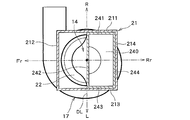
- FIG. 2 is a cross-sectional view taken along the line IIA-IIA in FIG.
- FIG. 2 is a cross-sectional view taken along the line IIB-IIB in FIG.
- FIG. 2 is a cross-sectional view taken along the line IIC-IIC in FIG.
- FIG. 2 is a cross-sectional view taken along line IID-IID in FIG.
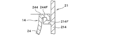
- FIG. 3 is an enlarged cross-sectional view illustrating a region (IIIA to IIIC) surrounded by a one-dot chain line in FIG.
- FIG. 3 is an enlarged cross-sectional view illustrating a region (IIIA to IIIC) surrounded by a one-dot chain line in FIG.
- FIG. 3 is an enlarged cross-sectional view illustrating a region (IIIA to IIIC) surrounded by a one-dot chain line in FIG.
- It is a schematic perspective view which shows the structure of a 1st switching door. It is a schematic sectional drawing which shows the state in which only external air is taken in in the air intake housing of a centrifugal blower. It is a schematic sectional drawing which shows the state in which only internal air is taken in in the air intake housing of a centrifugal blower.
- a centrifugal blower 1 shown in FIG. 1 is a single suction centrifugal blower.
- the centrifugal blower 1 has an impeller 2.
- the impeller 2 has a plurality of blades 3 forming a blade row 3A arranged in the circumferential direction on the outer peripheral portion thereof.
- the impeller 2 is driven to rotate about the rotation axis Ax by the motor 13, and the air sucked from the upper side in the axial direction (one end side in the axial direction) into the radially inner space of the blade row of the impeller 2 is directed outward in the radial direction. And blow out.
- the direction of the rotation axis Ax is referred to as the axial direction or the vertical direction, and the upper side and the lower side in FIGS. 1 and 2 are respectively referred to as “axially upper side” and “axially lower side”. Call. However, this does not mean that the direction of the rotation axis Ax coincides with the vertical direction when the air conditioner is actually incorporated in a vehicle.
- the direction of the radius of a circle drawn on a plane perpendicular to the rotation axis Ax around an arbitrary point on the rotation axis Ax is referred to as a radial direction.
- the circumferential direction of the circle is called the circumferential direction or the circumferential direction.
- the impeller 2 includes an inner deflection member 9 formed integrally with the impeller 2.
- the inner deflection member 9 is sometimes called a cone portion.
- the inner deflection member 9 is a rotating body in a geometric sense, and has a side peripheral portion 10 and a disc-shaped central portion 11. In the central portion 11, the rotating shaft 12 of the motor 13 is connected to the impeller 2.
- the side peripheral portion 10 is curved such that the contour line in the meridional section of the outer peripheral surface of the side peripheral portion 10 becomes steep as it approaches the central portion 11.
- the side circumferential portion 10 has a contour line in the meridional section of the outer circumferential surface of the side circumferential portion 10 that does not curve from the central portion 11 toward the blade row 3A (the cross section is linear). There is also.
- the impeller 2 is accommodated in a substantially cylindrical internal space of the scroll housing 17.
- the scroll housing 17 has a suction port 22 that opens upward in the axial direction, and a discharge port 170 (see FIG. 2). As shown in FIG. 2, when the scroll housing 17 is viewed from the axial direction, the discharge port 170 extends substantially in the tangential direction of the outer peripheral surface of the scroll housing 17. The discharge port 170 is not visible in FIG.
- the scroll housing 17 has a partition wall 20 that extends radially inward from the outer peripheral wall 17 ⁇ / b> A of the scroll housing 17.
- the partition wall 20 divides the region between the inner peripheral surface of the scroll housing 17 and the outer peripheral surface of the impeller 2 in the internal space of the scroll housing 17 in the axial direction (up and down), and An upper first air flow path 18 and a lower second air flow path 19 extending in the circumferential direction along the outer peripheral wall 17A are formed.
- a separation cylinder 14 is inserted into the scroll housing 17 via a suction port 22.
- the cross section (meaning a cross section orthogonal to the rotation axis Ax) of the upper portion 24 (entrance side end portion) of the separation cylinder 14 is generally rectangular.
- the cross section of the central portion 15 of the separation cylinder 14 is circular (or generally circular).
- the cross-sectional shape of the separation cylinder 14 smoothly transitions from a rectangle to a circle as it approaches the central portion 15 from the upper portion 24. Further, the position of the center of the cross section of the separation cylinder 14 changes smoothly as it approaches the central portion 15 from the upper portion 24.
- the lower portion 16 (exit side end portion) of the separation cylinder 14 has a flare shape that increases in diameter as it approaches the lower end, and the lower end is circular.
- the lower portion 16 from the central portion 15 of the separation cylinder 14 passes through the space on the radially inner side of the suction port 22 and extends in the axial direction to the space 4 on the radially inner side of the blade row 3A of the impeller 2.
- the upper end of the separation cylinder 14 is positioned outside the scroll housing 17 (above the suction port 22 in the axial direction).
- the lower end of the separation cylinder 14 is located in the space 4 on the radially inner side of the blade row 3 ⁇ / b> A of the impeller 2.
- the filter 35 is disposed in the space above the scroll housing 17 and the components of the centrifugal blower 1 are stacked in the vertical direction. , Can be consolidated in a compact.
- the separation cylinder 14 It is impossible or impossible if possible to integrally form the separation cylinder 14 having the illustrated shape by the resin injection molding technique. Therefore, it is preferable to manufacture the separation cylinder 14 by connecting two or more pieces separately injection-molded by a technique such as adhesion or fitting.
- the separation cylinder 14 is configured to change the flow of air sucked into the scroll housing 17 into a first air flow passing through the first passage 14A outside the separation cylinder 14 and a second passage passing through the second passage 14B inside the separation cylinder 14.
- the first air flow passes through the ring-shaped region outside the outer peripheral surface of the separation cylinder 14 in the suction port 22 of the scroll housing 17, and the upper half 5 (portion close to the suction port 22) of the impeller 2.
- the second air flow enters the inside of the separation cylinder 14 from the upper end of the separation cylinder 14 and flows into the lower half 6 (part far from the suction port 22) of the blade row of the impeller 2.
- the ring-shaped region outside the outer peripheral surface of the separation cylinder 14 in the suction port 22 of the scroll housing 17 is the first suction port of the scroll housing 17, and the opening at the upper end of the separation tube 14 is the second suction port of the scroll housing 17.
- An air intake housing 21 is connected to the scroll housing 17.
- the scroll housing 17 and the air intake housing 21 may be integrally formed, or may be connected by a method such as screwing, bonding, or fitting after being separately manufactured.
- the scroll housing 17 and the air intake housing 21 form part of the air conditioner casing.
- the air intake housing 21 has a first opening (outside air inlet) 25, a second opening (inside air inlet) 26, and a third opening (inside air inlet) 27.
- the first opening 25 is connected to an outlet (not shown) of an outside air introduction path provided in the vehicle or is in the vicinity of the outlet, and the outside air (air taken from outside the vehicle through the first opening 25). ) Can be introduced into the air intake housing 21.
- the 2nd opening 26 and the 3rd opening 27 are connected with the exit (not shown) of the inside air introduction path with which the vehicle was equipped, or are in the vicinity of the exit, and the 2nd and / or 3rd openings 26 and 27 are opened.
- the inside air can be introduced into the air intake housing 21 through the air intake housing 21.
- each of the first opening 25, the second opening 26, and the third opening 27 is a rectangle that extends in the lateral direction (LR direction) of the vehicle.
- the second opening 26 and the third opening 27 are two openings divided by a partition member (not shown).
- the second opening 26 and the third opening 27 are not limited to this, and one continuous opening without providing the partition member. The role as the 2nd opening 26 and the 3rd opening 27 can be given.
- the first switching door 33 includes a closing body 333 having an arc-shaped cross section supported on a rotating shaft 33 a via a pair of fan-shaped supports 331 and 332.
- a window (opening) is formed between the edge 33e extending in the longitudinal direction of the closing body 333 and the rotating shaft 33a, and air can pass through the window.
- the first switching door 33 can be turned around the rotation axis by an actuator 335 such as a rotary motor.
- the first switching door 33 may be called a rotary door.
- the structure of the second switching door 34 is the same as that of the first switching door 33.
- the rotating shaft of the second switching door 34 is denoted by reference numeral 34a
- the pair of fan-shaped supports of the second switching door 34 are denoted by reference numerals 341 and 342
- the closed body of the second switching door 34 is denoted by reference numeral 343, and the closing is performed.
- Reference numerals 34e are respectively attached to edges extending in the longitudinal direction of the body 343.
- the first switching door 33 has a first position (FIG. 5B) that closes the first opening 25 and opens the second opening 26, and a second position that opens the first opening 25 and closes the second opening 26 ( 5A).
- the second switching door 34 can move between a first position (FIG. 5A) where the third opening 27 is closed and a second position (FIG. 5B) where the third opening 27 is opened.
- a filter 35 is provided for removing contaminants such as dust and particles and off-flavors contained in the air.
- the filter 35 is provided closer to the inlet opening side of the separation cylinder 14 than the operating range of the first switching door 33 and the second switching door 34.
- the filter 35 is configured, for example, by bending a nonwoven fabric having a predetermined air permeability into a pleat shape. In order to remove off-flavors, odor removing substances such as activated carbon may be attached.
- the filter 35 is inserted into a slot (not shown) or a rail provided in the air intake housing 21 and is held at a position close to the upper portion 24 of the separation cylinder 14, that is, the inlet side end.
- FIG. 2A which is a cross-sectional view taken along the line IIA-IIA in FIG. 1, when the filter 35 (dotted in FIG. 2) is viewed from the upstream side with respect to the air flow direction, the filter 35 is rectangular. (Usually rectangular or square).
- the filter 35 is divided into two regions, a first region 35A and a second region 35B, by a virtual dividing line DL crossing the periphery of the filter 35.
- the virtual dividing line DL is a straight line orthogonal to the opposite side of a quadrangle (more specifically, a rectangle or a square) constituting the surface of the filter 35, and the quadrangle corresponding to the surface shape of the filter 35 is the first region 35 ⁇ / b> A.
- it is divided into two quadrangles (more specifically, a rectangle) corresponding to the second region 35B.
- FIG. 2A the rectangular upper end portion (inlet opening) of the separation cylinder 14 viewed through the filter 35 is drawn with a broken line.
- the peripheral edge of the upper end portion is composed of peripheral edge portions 241, 242, 243, and 244 respectively corresponding to four sides of the rectangle.
- the opening region 240 of the inlet opening of the separation cylinder 14 surrounded by the peripheral portions 241, 242, 243 and 244 coincides with the first region 35 A of the filter 35.
- the walls 211, 212, 213, and 214 of the air intake housing 21 are indicated with hatching.
- FIGS. 3A, 3B, and 3C A connection structure between the wall 214 of the air intake housing 21 and the peripheral portion 244 at the upper end of the separation cylinder 14 is shown in FIGS. 3A, 3B, and 3C.
- the connection structure between the wall body 211 and the peripheral portion 241 and the connection structure between the wall body 213 and the peripheral portion 243 can be the same as those described in FIGS. 3A, 3B, and 3C.
- the flange 244 ⁇ / b> F that protrudes outward from the peripheral portion 244 is placed on the flange 214 ⁇ / b> F that protrudes from the wall body 214 of the air intake housing 21.
- complementary flanges that engage with each other are formed on the flanges 244F and 214F shown in FIG. 3A.
- the wall body 214 of the air intake housing 21 and the upper part of the separation cylinder 14 are integrally formed.
- the first switching door 33 is set to the second position, the first opening 25 is opened, and the second opening 26 is closed. Further, the second switching door 34 is set to the first position, and the third opening 27 is closed.
- the outside air AE introduced into the air intake housing 21 from the first opening 25 passes through the second region 35B of the filter 35, passes through the first passage 14A outside the separation cylinder 14, and the impeller 2 blades.
- the lower half 6 of the blade row of the impeller 2 passes through the first air flow flowing into the upper half 5 of the row 3A, the first region 35A of the filter 35, and the second passage 14B inside the separation cylinder 14. Forming a second air stream flowing into the.
- the first operation mode is sometimes called the outside air mode.
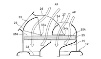
- the first switching door 33 is set to the second position, the first opening 25, the first opening 25 is opened, and the second opening 26 is closed. Further, the second switching door 34 is set to the second position, and the third opening 27 is opened.
- the introduced outside air AE introduced into the air intake housing 21 from the first opening 26 passes through the second region 35B of the filter 35, passes through the first passage 14A outside the separation cylinder 14, and passes through the impeller.
- a first air flow flowing into the upper half 5 of the second blade row 3A is formed.
- the inside air AR introduced from the third opening 27 passes through the first region 35A of the filter 35, passes through the second passage 14B inside the separation cylinder 14, and enters the lower half 6 of the blade row 3A of the impeller 2.
- the closing body 343 of the second switching door 34 in the second position has a space above the filter 35 as a space on the first opening 25 side and a space on the third opening 27 side.
- the outside air AE and the inside air AR are prevented from being mixed above the filter 35. That is, the closing body 343 of the second switching door 34 in the second position has a function of a separation wall that separates the outside air AE and the inside air AR above the filter 35 in the second operation mode.
- the second operation mode is sometimes called the inside / outside air two-layer flow mode.
- the first switching door 33 is set to the first position, the first opening 25 is closed, and the second opening 26 is opened. Further, the second switching door 34 is set to the second position, and the third opening 27 is opened.
- the inside air AR introduced into the air intake housing 21 from the second opening 26 and the third opening 27 passes through the second region 35B of the filter 35 and passes through the first passage 14A outside the separation cylinder 14.
- the first air flow flowing into the upper half 5 of the blade row 3A of the impeller 2 and the first region 35A of the filter 35, the second passage 14B inside the separation cylinder 14, and the blade row of the impeller 2 Forming a second air flow flowing into the lower half 6 of the first half.
- the third mode of operation is sometimes referred to as shy mode
- the second operation mode (inside / outside air two-layer flow mode) is a heating operation in which the vehicle interior is heated quickly while preventing the front window from fogging from the cold state, particularly in winter or when the temperature is relatively low. Used when performing.
- the third operation mode (inside air mode) is set at the initial stage of the heating operation, and when the temperature inside the passenger compartment starts to rise, the second operation mode is promptly shifted.
- this heating operation is performed by automatic control, the outside air AE is blown from the defroster outlet (not shown) of the passenger compartment to the front window (not shown), and the inside air AR is blown to the foot outlet (not shown) of the passenger compartment. ) Will be blown out toward the passengers.
- the external air AE flowing into the upper half 5 of the blade row 3A of the impeller 2 passes through the first air flow path 18 to the defroster outlet.
- the inside air AR that is supplied and flows into the lower half 6 of the blade row 3 ⁇ / b> A of the impeller 2 is supplied to the foot outlet through the second air flow path 19.
- an event which is a safety problem such as fogging of the front window may occur.
- the first region which is a region where the rectangular inlet opening of the separation cylinder exists, includes the inlet opening.
- the inlet opening Located in the center of the cross section of the air intake housing.
- second region A and “second region B” for convenience of explanation
- the filter 35 when the filter 35 is viewed from the upstream side with respect to the air flow direction, the filter is divided into the first region 35A and the second region by the virtual dividing line DL crossing the periphery of the filter 35.
- the region 35B is divided into two regions (both are rectangular in the illustrated example)
- the opening region 240 of the inlet opening (which is rectangular in the illustrated example) of the separation cylinder 14 coincides with the first region 35A. .
- the ratio of the area of the first region 35A to the area of the second region 35B is 5: 5, but is not limited thereto, and may be 6: 4 or 4: 6, for example.
- the virtual dividing line DL divides the surface of the filter 35 into two rectangles, and this is preferable.
- the virtual dividing line DL is not limited to this, and is divided into two trapezoids. Also good. That is, the angle formed between the opposite side of the rectangle (which may be a square) constituting the surface of the filter 35 by the virtual dividing line DL may not be 90 degrees.
- the virtual dividing line DL is preferably a straight line, but may be somewhat curved.
- the structure of the air intake housing 21 can be modified as shown in FIG.
- the air intake housing 21A shown in FIG. 6 has openings 25A and 25B as outside air introduction ports and openings 26A and 27A as inside air introduction ports.
- the opening 25A and the opening 26A are opened and closed by a first switching door 41 having a rotating shaft 41a and a closing portion extending from the rotating shaft 41a.
- the opening 25B and the opening 27A are opened and closed by a second switching door 42 having a rotating shaft 42a and a closing portion extending from the rotating shaft 42a.
- the 1st switching door 41 and the 2nd switching door 42 may be called a cantilever door.
- a separation wall 43 is provided in the air intake housing 21 ⁇ / b> A upstream of the filter 35 (upward in FIG.
- the separation wall 43 By this separation wall 43, the air introduced into the air intake housing 21A from the openings 25B and 27A is introduced into the separation cylinder 14, and the air introduced into the air intake housing 21A from the openings 25A and 26A is separated.
- the scroll housing 17 is introduced through the outside of the cylinder 14. Accordingly, when the outside air is introduced from the opening 25A to the air intake housing 21A and the inside air is introduced from the opening 27A to the air intake housing 21A, the separation wall 43 separates the outside air from the inside air and Try not to mix.
- the distance S is preferably in the range of 3 mm to 5 mm. If the distance is shorter than 3 mm, abnormal noise may occur when air flows through the distance S. If it is longer than 5 mm, the amount of the outside air mixed into the inside air increases in the inside / outside air two-layer flow mode, and the separability of the two air flows to be separated deteriorates.
- the configuration of the portion below the filter 35 is the same as that of the embodiment shown in FIGS. Therefore, in the embodiment shown in FIG. 6 as well, the filter 35 can be used uniformly as in the embodiment shown in FIGS.
- the structure of the air intake housing 21 and the configuration of the separation cylinder 14 can be modified as shown in FIG.
- the center of the cross section perpendicular to the rotation axis Ax is not gradually shifted in the direction perpendicular to the axial direction, and is symmetrical with respect to a plane that includes the rotation axis Ax and is perpendicular to the paper surface of FIG. Is formed.
- the center of the cross section perpendicular to the rotational axis Ax of the air intake housing 21B shown in FIG. 7 is gradually shifted in the direction perpendicular to the axial direction, and as a result, the embodiment of FIGS.
- the opening area surrounded by the peripheral edge of the inlet opening of the separation cylinder 14 ⁇ / b> C coincides with the first area of the filter 35. Therefore, in the embodiment shown in FIG. 7 as well, the filter 35 can be used uniformly as in the embodiment shown in FIGS.
- the separation cylinder 14C By configuring the separation cylinder 14C as shown in FIG. 7, the separation cylinder 14C can be formed in a symmetrical shape, and productivity can be improved.
- the virtual dividing line DL is defined by the position of the upper end 243a of the peripheral edge portion 243 at the upper end of the separation cylinder 14 and the lower end 43e of the separation wall 43 (the filter side end of the closing body 343 when the second door 34 is in the second position). If the position is shifted to the first region 35A side by the distance S, it can be considered that the position is shifted to the second region 35B side by the distance S from the lower end 43e of the separation wall 43.
- the virtual dividing line DL is at the position of the lower end 43e of the separation wall 43 when the position of the upper end 243a of the peripheral edge portion 243 at the upper end of the separation cylinder 14 and the position of the lower end 43e of the separation wall 43 are not shifted. Can be considered.
- the virtual dividing line DL that divides into two regions of the first region 35A and the second region 35B when the filter 35 is viewed from the upstream side in the air flow direction is in the vicinity of the lower end 43e of the separation wall 43. It is a dividing line assumed to be located.
- Second air flow path 20 partition wall 21, 21A, 21B Air intake housing 22 Suction port 24 Entrance end (upper part) 240 Opening area 241, 242, 243, 244 Periphery (peripheral part) 25, 25A, 25B Outside air inlet (opening) 26, 27, 26A, 27A Inside air inlet (opening) 35 Filter DL virtual dividing line 35A first region 35B 2nd area
Landscapes
- Engineering & Computer Science (AREA)
- Mechanical Engineering (AREA)
- General Engineering & Computer Science (AREA)
- Physics & Mathematics (AREA)
- Thermal Sciences (AREA)
- Structures Of Non-Positive Displacement Pumps (AREA)
Abstract
【課題】分離筒を備えた車両用の片吸込型の遠心送風機において、吸込みモードに関わらず、フィルタの全領域を空気が通過するようにして、フィルタを有効に利用する。 【解決手段】空気の流れ方向に関して上流側からフィルタ(35)を見て、フィルタの周縁を横切る仮想分割線(DL)によりフィルタを第1領域(35A)及び第2領域(35B)の二つの領域(例えば2つの長方形の領域)に分割したときに、分離筒(14;14B)の入口側端部(24)の周縁(241,242,243,244)により囲まれる開口領域(240)が第1領域(35A)と一致するように、分離筒(14;14B)または空気取入ハウジング(21;21A;21B)を構成する。
Description
本発明は、二層流式の車両用空調装置のための遠心送風機に関する。
車両用空調装置の分野において、二層流式の車両用空調装置が知られている。この形式の空調装置は、互いに分離された2つの送風路すなわち第1送風路及び第2送風路と、これらの2つの送風路に空気を流す単一の遠心送風機とを備えている。遠心送風機は、スクロールハウジングと、スクロールハウジングに送られる空気を取り込むための空気取入ハウジングとを有している。
遠心送風機は、スクロールハウジングの吸込口及び羽根車の翼列の径方向内側の空間に挿入された分離筒を有している(例えば特許文献1、2を参照)。羽根車の翼列の径方向外側とスクロールハウジングとの間の空間は分離壁により上下に分割され、これにより第1送風路に連通する第1空気流路及び第2送風路に連通する第2空気流路が形成されている。分離筒は、当該分離筒の外側の第1通路を流れる第1空気流が翼列の上半部に導入された後に第1空気流路に流入し、分離筒の内側の第2通路を流れる第2空気流が翼列の下半部に導入された後に第2空気流路に流入するように設けられている。
空気取入ハウジングは、車室外の空気(外気)を取り込むための外気導入口と、車室内の空気(内気)を取り込むための内気導入口とを有する。通常、外気導入口と内気導入口とはスクロールハウジング中心軸に関して互いに反対の位置に設けられている。多くの場合、外気導入口は車両の前方側に設けられ、内気導入口は車両の後方側に設けられている。特許文献2の遠心送風機では、外気導入口及び内気導入口が設けられている領域と、分離筒の入口側端部との間に、フィルタが設けられる。
空調装置が外気モードで運転されると、外気導入口から空気取入ハウジングに導入された外気は、フィルタの中央部を通って分離筒内に導入される空気流と、フィルタの前記中央部よりも前部のみを通って分離筒の外側へ流れる空気流とに分かれたのち、スクロールハウジングに吸い込まれる。
空調装置が内気モードで運転されると、内気導入口から空気取入ハウジングに導入された外気は、フィルタの中央部を通って分離筒内に導入される空気流と、フィルタの前記中央部よりも後部のみを通って分離筒の外側へ流れる空気流とに分かれたのち、スクロールハウジングに吸い込まれる。
そして空調装置が内外気二層流モードで運転されると、内気導入口から空気取入ハウジングに導入された内気は、フィルタの中央部を通って分離筒内に導入され、外気導入口から空気取入ハウジングに導入された外気は、フィルタの前記中央部よりも前部のみを通って分離筒の外側へ流れ、スクロールハウジングに吸い込まれる。
このように特許文献2の遠心送風機では、フィルタの中央部は動作モードに関わらず常に空気が通過する一方、フィルタの前部や後部は動作モードによって空気が通過しない。
このため、フィルタの中央部は、フィルタの前部や後部に対し、相対的に早期に、フィルタに期待される集塵性能や脱臭性能が劣化することとなり、フィルタの有効な利用が妨げられていた。
本発明は、吸込みモードに関わらず、フィルタの全領域を空気が通過するようにして、該フィルタを有効に利用することができる、分離筒を備えた車両用の片吸込型の遠心送風機を提供することを目的としている。
本発明の好適な一実施形態によれば、車両用の片吸込型の遠心送風機であって、モータと、周方向翼列を形成する複数の翼を有し、前記モータによって回転軸周りに回転駆動されて、軸方向の一端側から前記翼列の半径方向内側の空間に吸入した空気を、半径方向外側に向けて吹き出す羽根車と、前記羽根車を収容する内部空間と、前記軸方向の一端側に開口する吸込口と、周方向に開口する吐出口と、を有するスクロールハウジングと、前記スクロールハウジングの前記内部空間のうちの前記スクロールハウジングの内周面と前記羽根車の外周面との間の領域、並びに前記吐出口の内部空間を、前記軸方向に分割して第1空気流路及び第2空気流路を形成する仕切壁と、前記吸込口の半径方向内側及び前記羽根車の前記翼列の半径方向内側を通って前記軸方向に延びる分離筒であって、前記吸込口から前記スクロールハウジング内に吸入される空気の流れを、分離筒の外側を通る第1空気流と、前記分離筒の内側を通る第2空気流とに分割するように設けられ、かつ、前記第1空気流を半径方向外向きに転向して前記第1空気流路に案内するとともに、前記第2空気流を半径方向外向きに転向して前記第2空気流路に案内する出口側端部を有している、分離筒と、車両の外気を取り込むための少なくとも1つの外気導入口と、車両の内気を取り込むための少なくとも1つの内気導入口と、を有し、前記外気導入口から取り込んだ外気を前記分離筒の外側に流すとともに前記内気導入口から取り込んだ内気を前記分離筒の内側に流すことができるように構成された空気取入ハウジングと、前記内気導入口及び前記外気導入口と、前記分離筒の入口側端部との間において、前記入口側端部に近接する位置で、前記空気取入ハウジング内で保持されるフィルタと、を備え、空気の流れ方向に関して上流側から前記フィルタを見て、前記フィルタの周縁を横切る仮想分割線により前記フィルタを第1領域及び第2領域の二つの領域に分割したときに、前記分離筒の前記入口側端部の周縁により囲まれる開口領域が前記第1領域と一致している、遠心送風機が提供される。
上記実施形態によれば、分離筒の入口側端部の周縁により囲まれる開口領域が、二つの領域に分割されたフィルタの第1領域と一致して設けられるので、分離筒の開口領域の外側の領域は、二つの領域に分割されたフィルタの第2領域と一致して設けられる。そして、分離筒の開口領域を通過する空気は、吸込みモードに関わらずフィルタの第1領域を通過し、分離筒の開口領域の外側の領域を通過する空気は、吸込みモードに関わらずフィルタの第2領域を通過する。すなわち、上記実施形態により、遠心送風機に吸込まれる空気を常に第1領域と第2領域とに通過させて、吸込みモードに関わらずフィルタの全領域を有効に利用することができる。
以下に添付図面を参照して本発明の車両用の遠心送風機の実施形態について説明する。
各図では、Rが車両の右方、Lが車両の左方、Frが車両の前方、Rrが車両の後方をそれぞれ意味している。但し、車両に対する遠心送風機の設置方向は、図示例に限定されるものではない。
図1に示す遠心送風機1は、片吸込型の遠心送風機である。遠心送風機1は、羽根車2を有する。羽根車2は、その外周部分に、周方向に並んだ翼列3Aを形成する複数の翼3を有している。羽根車2は、モータ13により回転軸線Ax周りに回転駆動され、軸方向上側(軸方向一端側)から羽根車2の翼列の半径方向内側の空間に吸入した空気を、半径方向外側に向けて吹き出す。
なお、本明細書において、説明の便宜上、回転軸線Axの方向を軸方向または上下方向と呼び、図1及び図2の上側及び下側をそれぞれ「軸方向上側」及び「軸方向下側」と呼ぶ。しかしながら、このことによって、空調装置が実際に車両に組み込まれた場合に回転軸線Axの方向が鉛直方向に一致するものと限定されるわけではない。また、本明細書においては、特別な注記が無い限り、回転軸線Ax上の任意の点を中心として回転軸線Axと直交する平面上に描かれた円の半径の方向を半径方向と呼び、当該円の円周方向を周方向または円周方向と呼ぶ。
羽根車2は、当該羽根車2と一体成形された内側偏向部材9を含む。内側偏向部材9は、コーン部と呼ばれることもある。この内側偏向部材9は、幾何学的な意味における回転体であり、側周部10と、円板形の中央部11とを有している。中央部11において、モータ13の回転軸12が羽根車2に連結される。この例では、側周部10は、この側周部10の外周面の子午断面における輪郭線が、中央部11に近づくに従って急勾配となるように湾曲している。図示しない他の例では、側周部10は、この側周部10の外周面の子午断面における輪郭線が、中央部11から翼列3Aに向けて湾曲しない(断面が直線状である)場合もある。
羽根車2は、スクロールハウジング17の概ね円柱形の内部空間に収容される。スクロールハウジング17は、軸方向上側に開口する吸込口22と、吐出口170(図2を参照)とを有している。図2に示すように、スクロールハウジング17を軸方向から見た場合、吐出口170はスクロールハウジング17の外周面の概ね接線方向に延びている。吐出口170は図1では見えない。
スクロールハウジング17は、当該スクロールハウジング17の外周壁17Aから半径方向内側に向けて延びる仕切壁20を有している。この仕切壁20は、スクロールハウジング17の内部空間のうちのスクロールハウジング17の内周面と羽根車2の外周面との間の領域を軸方向に(上下に)分割して、スクロールハウジング17の外周壁17Aに沿って周方向に延びる上側の第1空気流路18及び下側の第2空気流路19を形成する。
スクロールハウジング17内には、吸込口22を介して、分離筒14が挿入されている。図2A~図2Dよりわかるように、分離筒14の上部24(入口側端部)の断面(回転軸線Axに直交する断面を意味する)は概ね長方形である。分離筒14の中央部15の断面は円形(又は概ね円形)である。分離筒14の断面形状は、上部24から中央部15に近づくに連れて、長方形から円形に滑らかに推移する。また、分離筒14の断面中心の位置は、上部24から中央部15に近づくに連れて滑らかに推移する。分離筒14の下部16(出口側端部)は、下端に近づくに従って拡径するフレア形状を有しているとともに、下端は円形である。
分離筒14の中央部15から下部16は、吸込口22の半径方向内側の空間を通り、羽根車2の翼列3Aの半径方向内側の空間4まで軸方向に延びている。分離筒14の上端は、スクロールハウジング17の外側(吸込口22よりも軸方向上側)に位置している。分離筒14の下端は、羽根車2の翼列3Aの半径方向内側の空間4内に位置している。
図1および図2A~図2Dのように遠心送風機1および分離筒14を構成することで、フィルタ35をスクロールハウジング17の上方空間に配置し、遠心送風機1の構成要素を上下方向に積層して、コンパクトに集約することができる。
図示された形状を有する分離筒14を、樹脂射出成形技術により一体成形することは不可能であるか、可能だとしても非常に困難である。従って、別々に射出成形された2つまたはそれ以上のピースを例えば接着または嵌め込み等の手法により連結することによって、分離筒14を製造することが好ましい。
分離筒14は、スクロールハウジング17内に吸入される空気の流れを、分離筒14の外側の第1通路14Aを通る第1空気流と、分離筒14の内側の第2通路14Bを通る第2空気流とに分割する。第1空気流は、スクロールハウジング17の吸込口22のうちの分離筒14の外周面より外側のリング状領域を通り、羽根車2の翼列の上半部5(吸込口22に近い部分)に流入する。第2空気流は、分離筒14の上端から分離筒14の内側に入り、羽根車2の翼列の下半部6(吸込口22から遠い部分)に流入する。従って、スクロールハウジング17の吸込口22のうちの分離筒14の外周面より外側のリング状領域がスクロールハウジング17の第1吸入口、分離筒14の上端の開口がスクロールハウジング17の第2吸入口、と見なすこともできる。
スクロールハウジング17には、空気取入ハウジング21が連結されている。スクロールハウジング17と空気取入ハウジング21とは、一体成形されていてもよいし、別々に作製された後にネジ止め、接着、嵌め込み等の手法により連結されてもよい。スクロールハウジング17及び空気取入ハウジング21は空調装置ケーシングの一部を成す。
空気取入ハウジング21は、第1開口(外気導入口)25、第2開口(内気導入口)26及び第3開口(内気導入口)27を有している。第1開口25には、車両に設けられた外気導入路の出口(図示せず)と連結されているかあるいは当該出口の近傍にあり、第1開口25を介して外気(車両外部から取り入れた空気)を空気取入ハウジング21内に導入することができる。第2開口26及び第3開口27は車両に備えられた内気導入路の出口(図示せず)と連結されているかあるいは当該出口の近傍にあり、第2及び/又は第3開口26,27を介して内気(車室内空気)を空気取入ハウジング21内に導入することができる。
例示的かつ非限定的な実施形態においては、図2Aに示すように、第1開口25、第2開口26及び第3開口27の各々は、車両の横方向(L-R方向)に延びる長方形の孔とすることができる。第2開口26及び第3開口27は、仕切部材(図示せず)により分割された2つの開口であるが、これに限定されるものではなく、仕切部材を設けずに連続した一つの開口に第2開口26及び第3開口27としての役割を持たせることができる。
空気取入ハウジング21内には2つの切換ドア(第1切換ドア33,第2切換ドア34)が設けられている。図4に示すように、第1切換ドア33は、回転軸33aに、一対の扇形の支持体331,332を介して支持される円弧形の断面を有する閉鎖体333を有する。閉鎖体333の長手方向に延びる縁33eと回転軸33aとの間は窓(開口)となっており、この窓を空気が通過することができる。第1切換ドア33は、回転モータ等のアクチュエータ335により、回転軸線周りに旋回することができる。第1切換ドア33は、ロータリ式ドアと呼ばれることもある。
第2切換ドア34の構造は第1切換ドア33と同じである。第2切換ドア34の回転軸には符号34aが、第2切換ドア34の一対の扇形の支持体には符号341,342が、第2切換ドア34の閉鎖体には符号343が、そして閉鎖体343の長手方向に延びる縁には符号34eが、それぞれ付けられている。
第1切換ドア33は、第1開口25を閉鎖しかつ第2開口26を開放する第1位置(図5B)と、第1開口25を開放しかつ第2開口26を閉鎖する第2位置(図5A)との間で移動することができる。第2切換ドア34は、第3開口27を閉鎖する第1位置(図5A)と、第3開口27を開放する第2位置(図5B)との間で移動することができる。
空気取入ハウジング21内には、第1~第3開口25~27と、分離筒14の上部24の上端部に設けられる入口開口(図2に示す開口領域240に対応)との間に、空気中に含まれるダスト、パーティクル等の汚染物質や異臭を除去するためのフィルタ35が設けられている。フィルタ35は、第1切換ドア33、第2切換ドア34の稼働範囲よりも、分離筒14の入口開口側に設けられる。フィルタ35は、例えば所定の通気性を有する不織布をひだ状に折り曲げて構成される。異臭を除去するために、活性炭等の臭気除去物質が取り付けられることもある。また、フィルタ35は、空気取入ハウジング21内に設けられた図示しないスロット内またはレール内に挿入されて、分離筒14の上部24すなわち入口側端部に近接する位置に保持されている。
図1のIIA-IIA線に沿った断面図である図2Aに示すように、空気の流れ方向に関して上流側からフィルタ35(図2ではドットが付けられている)を見ると、フィルタ35は四角形(通常は、長方形または正方形)である。フィルタ35を、当該フィルタ35の周縁を横切る仮想分割線DLにより第1領域35A及び第2領域35Bの二つの領域に分割してみる。図示例では、仮想分割線DLは、フィルタ35の表面を構成する四角形(より詳細には長方形または正方形)の対辺に直交する直線であり、フィルタ35の表面形状に対応する四角形を第1領域35A及び第2領域35Bに対応する2つの四角形(より詳細には長方形)に分割している。
図2Aには、フィルタ35を透かして見た分離筒14の長方形の上端部(入口開口)が破線で描かれている。上端部の周縁は、長方形の4つの辺にそれぞれ対応する周縁部分241,242,243,244から構成されている。平面視において、周縁部分241,242,243,244により囲まれた分離筒14の入口開口の開口領域240は、フィルタ35の第1領域35Aと一致している。なお、図2Aにおいて、空気取入ハウジング21の壁体211,212,213,214はハッチング付きで表示されている。
上記構成により、フィルタ35の第1領域35Aを通過する空気のほぼ全てが分離筒14内に流入し、フィルタ35の第2領域35Bを通過する空気のほぼ全てが分離筒14の外側を通って、スクロールハウジング17の吸込口22に流入するようになる。
空気取入ハウジング21の壁体214と分離筒14の上端の周縁部分244との接続構造が図3A,図3B,図3Cに示されている。壁体211と周縁部分241との接続構造、並びに壁体213と周縁部分243との接続構造も、図3A,図3B,図3Cに記載されたものと同様とすることができる。
図3Aの例では、周縁部分244から外側に張り出すフランジ244Fが、空気取入ハウジング21の壁体214から張り出すフランジ214Fの上に載っている。図3Bの例では、図3Aに示した各フランジ244F、214Fに、互いに係合する相補的な凹凸を形成している。図3Cの例では、空気取入ハウジング21の壁体214と分離筒14の上部とが一体成形されている。このような構成を採用することにより、分離筒14内に流入する空気(例えば、第3開口から空気取入ハウジング21に導入した内気)が、分離筒14の外側の空間に漏出することを防止または抑制することができる。
次に、図1~図3に示す車両用空調装置の動作について説明する。
車両用空調装置の第1の動作モードでは、図5Aに示すように、第1切換ドア33が第2位置とされて第1開口25が開放され、第2開口26が閉鎖される。また、第2切換ドア34が第1位置とされて第3開口27が閉鎖される。この場合、第1開口25から空気取入ハウジング21内に導入された外気AEは、フィルタ35の第2領域35Bを通り、分離筒14の外側の第1通路14Aを通って羽根車2の翼列3Aの上半部5に流入する第1空気流と、フィルタ35の第1領域35Aを通り、分離筒14の内側の第2通路14Bを通って羽根車2の翼列の下半部6に流入する第2空気流を形成する。第1の動作モードは、外気モードと呼ばれることもある
第2の動作モードでは、図1に示すように、第1切換ドア33が第2位置とされて第1開口25第1開口25が開放され、第2開口26が閉鎖される。また、第2切換ドア34が第2位置とされて、第3開口27が開放される。この場合、第1開口26から空気取入ハウジング21内に導入された導入された外気AEは、フィルタ35の第2領域35Bを通り、分離筒14の外側の第1通路14Aを通り、羽根車2の翼列3Aの上半部5に流入する第1空気流を形成する。また、第3開口27から導入された内気ARは、フィルタ35の第1領域35Aを通り、分離筒14の内側の第2通路14Bを通り、羽根車2の翼列3Aの下半部6に流入する第2空気流を形成する。なお、図1より明らかなように、第2位置にある第2切換ドア34の閉鎖体343は、フィルタ35の上方の空間を、第1開口25側の空間と第3開口27側の空間とに分割し、フィルタ35の上方で外気AEと内気ARとが混合されることを防止する。すなわち第2位置にある第2切換ドア34の閉鎖体343は、第2の動作モードのときに、フィルタ35の上方で外気AEと内気ARとを分離する分離壁の機能を有している。第2の動作モードは、内外気2層流モードと呼ばれることもある
第3の動作モードでは、図5Bに示すように、第1切換ドア33が第1位置とされて第1開口25が閉鎖され、第2開口26が開放される。また、第2切換ドア34が第2位置とされて、第3開口27が開放される。この場合、第2開口26及び第3開口27から空気取入ハウジング21内に導入された内気ARは、フィルタ35の第2領域35Bを通り、分離筒14の外側の第1通路14Aを通って羽根車2の翼列3Aの上半部5に流入する第1空気流と、フィルタ35の第1領域35Aを通り、分離筒14の内側の第2通路14Bを通って羽根車2の翼列の下半部6に流入する第2空気流を形成する。第3の動作モードは、内気モードと呼ばれることもある
第2の動作モード(内外気2層流モード)は、特に冬季または比較的気温が低い時期に、車室内が冷えている状態からフロントウインドウの曇りを防止しつつ速やかに車室内を暖める暖房運転を行う際に用いられる。あるいは、暖房運転の初期には第3の動作モード(内気モード)とされ、車室内の温度の上昇が開始されたら速やかに第2の動作モードに移行することも行われる。この暖房運転が自動制御により行われるときには、外気AEが車室のデフロスタ吹出口(図示せず)からフロントウインドウ(図示せず)に吹き付けられ、内気ARが車室のフット吹出口(図示せず)から乗客の足元に向けて吹き出される。
第2の動作モード(内外気2層流モード)が実行されるときには、羽根車2の翼列3Aの上半部5に流入する外気AEが第1空気流路18を介してデフロスタ吹出口に供給され、羽根車2の翼列3Aの下半部6に流入する内気ARが第2空気流路19を介してフット吹出口に供給される。このとき、外気AEに対して相対的に高湿度の内気ARがデフロスタ吹出口に供給される外気AEに混入すると、フロントウインドウの曇りという安全上問題となる事象が生じうる。また、内気ARに対して相対的に低温の外気AEがフット吹出口に供給される内気ARに混入すると、乗客に不快感を与える要因となり得る。従って、第2の動作モードが実行されるときには、内気ARに対して相対的に低湿度の外気AEの全てが第1空気流路18に流入し、かつ、外気AEに対して相対的に高温の内気ARの全てが第2空気流路19に流入することが望ましい。
ところで、先に背景技術の項でも説明したように、前述した特許文献2に記載された遠心送風機では、分離筒の長方形の入口開口が存在する領域である第1領域は、当該入口開口を含む空気取入ハウジングの断面の中央部に位置する。そして、当該断面内には、当該入口開口の両脇(前方及び後方)にそれぞれ位置する2つの長方形の領域(説明の便宜上、「第2領域A」、「第2領域B」と呼ぶ)が存在し、分離筒14内に流入せずに分離筒14の外側を流れる空気は、第2領域Aまたは第2領域Bのいずれかを通って、スクロールハウジング17内に流入する。
このように、特許文献2に記載された遠心送風機では、フィルタ35の第1領域、第2領域A、および第2領域Bのすべてを同時に空気が通過することがない。このため、空気がフィルタ35を通過する面積が限られて、遠心送風機全体としての通気抵抗が上昇し、送風量が確保できないおそれがある。また、3つの動作モードのうちのいずれのモードにおいてもフィルタ35の第1領域は常に空気が通過するので、第2領域Aや第2領域Bに対して相対的に早期にパーティクルが蓄積することや、汚染物質や異臭の除去能力が低下するおそれがある。このように、特許文献2に記載された遠心送風機は、フィルタ35の第1領域の集塵性能や脱臭性能が他の領域に対して早期に劣化することとなり、均一な利用ができず、フィルタ全体としての有効な利用が妨げられていた。更には、フィルタ35のうち一部の領域を利用しないことで、フィルタを通過する空気に対する通気抵抗が上昇し、遠式送風機としての送風能力を十分に発揮できないおそれがある。
一方、上記実施形態においては、前述したように、空気の流れ方向に関して上流側からフィルタ35を見たときに、フィルタ35の周縁を横切る仮想分割線DLにより前記フィルタを第1領域35A及び第2領域35Bの二つの領域(図示例ではいずれも長方形である)に分割したときに、分離筒14の入口開口(図示例では長方形である)の開口領域240が第1領域35Aと一致している。従って、分離筒14内に流入する空気のほぼ全てが、動作モードによらず単一の領域つまり第1領域35Aを通り、分離筒14内に流入せずに分離筒14の外側を流れる空気のほぼ全てが、動作モードによらず単一の領域つまり第2領域35Bを通る。このため、動作モードによらずフィルタ35の全領域に空気を通過させて、フィルタ全体としての有効な利用を行うことができる。また、動作モードによらずフィルタ35の全領域に空気を通過させることができるから、フィルタを通過する空気に対する通気抵抗の上昇を抑制し、遠式送風機としての送風能力を十分に発揮することができる。
上記実施形態では、第1領域35Aの面積と第2領域35Bの面積の比は5:5であるが、これには限定されず、例えば6:4または4:6でもよい。
上記実施形態では、仮想分割線DLは、フィルタ35の表面を2つの長方形に分割しており、こうすることが好ましいが、こうすることに限定されるものではなく、2つの台形に分割してもよい。つまり、仮想分割線DLがフィルタ35の表面を構成する長方形(正方形でもよい)の対辺と成す角度が90度でなくてもよい。仮想分割線DLは、直線であることが好ましいが、いくらか湾曲していても構わない。
空気取入ハウジング21の構造を図6に示すように改変することができる。図6に示す空気取入ハウジング21Aは、外気導入口としての開口25A,25Bと、内気導入口としての開口26A,27Aとを有している。開口25Aと開口26Aとは、回転軸41aとこの回転軸41aから延出する閉塞部を有する第1切換ドア41により開閉される。開口25Bと開口27Aとは、回転軸42aとこの回転軸42aから延出する閉塞部を有する第2切換ドア42により開閉される。第1切換ドア41と第2切換ドア42とは、片持式ドアと呼ばれることもある。フィルタ35の上流(図6では上方)において、空気取入ハウジング21A内に分離壁43が設けられている。この分離壁43により、開口25B,27Aから空気取入ハウジング21A内に導入された空気が分離筒14内に導入され、開口25A,26Aから空気取入ハウジング21A内に導入された空気が、分離筒14の外側を通ってスクロールハウジング17に導入されるようになっている。従って、開口25Aから空気取入ハウジング21Aに外気が導入され、かつ開口27Aから空気取入ハウジング21Aに内気が導入されるときに、分離壁43は、外気と内気を互いに分離して両者が互いに混じり合わないようする。
なお、前述した内外気2層流モードを実行する際に、デフロスタ吹出口に供給される低湿度の外気AEに、高湿度の内気ARが混合されることは可能な限り回避することが望ましい。このため、図6に示す実施形態では、空気の流れ方向に関して上流側からフィルタ35を見たときに、分離壁43の下端43e(フィルタ35近傍に位置する端縁)が、分離筒14の上端の入口開口つまり第1領域35A内に位置するように、分離筒14の上端の周縁部分243の上端243aの位置と下端43eとの位置が距離Sだけ第1領域35A側にずれている。この点については、後述する図7に示した実施形態でも同様である(分離壁43の下端43eと分離筒14Cの周縁部分の上端243bとの距離Sの位置ずれを参照)。距離Sの寸法としては、3ミリから5ミリの範囲が好ましい。3ミリより短いと、距離Sを空気が通流するときに異音が発生するおそれがある。5ミリより長いと、内外気二層流モードのときに、内気に混入する外気の量が多くなり、分離すべき2つの空気流の分離性が悪化する。
同様の理由により、図1~図5に示す実施形態においても、図1に示すように内外気2層流モードを実行する際には、第2位置にある第2切換ドア34の閉鎖体343の端縁34eの位置と分離筒14の上端の周縁部分243の上端243aの位置とが同様に距離Sだけ第1領域35A側にずれていることが好ましい。
図6に示す実施形態において、フィルタ35より下側の部分の構成は、図1~図5に示した実施形態と同じである。従って、図6に示す実施形態においても、図1~図5に示した実施形態と同様に、フィルタ35を均一に利用することができる。
空気取入ハウジング21の構造及び分離筒14の構成を図7に示すように改変することができる。図7に示す分離筒14Cは、回転軸線Axに直交する断面の中心が軸方向に直交する方向に徐々にずらされてはおらず、回転軸線Axを含み図7の紙面に垂直な平面に関して対称に形成されている。その代わりに、図7に示す空気取入ハウジング21Bの回転軸線Axに直交する断面の中心が軸方向に直交する方向に徐々にずらされており、その結果として、図1~図6の実施形態と同様に、分離筒14Cの入口開口の周縁により囲まれる開口領域がフィルタ35の第1領域と一致するようになっている。従って、図7に示す実施形態においても、図1~図6に示した実施形態と同様に、フィルタ35を均一に利用することができる。
図7のように分離筒14Cを構成することで、分離筒14Cを対称な形状に形成することができ、生産性を向上することができる。
なお、仮想分割線DLは、分離筒14の上端の周縁部分243の上端243aの位置と、分離壁43の下端43e(第2ドア34が第2位置のときの、閉塞体343のフィルタ側端部も含む)との位置が距離Sだけ第1領域35A側にずれている場合は、分離壁43の下端43eから距離Sだけ第2領域35B側にずれた位置にあるとみなすことができる。また、仮想分割線DLは、分離筒14の上端の周縁部分243の上端243aの位置と、分離壁43の下端43eとの位置がずれていない場合は、分離壁43の下端43eの位置にあるとみなすことができる。このように、空気の流れ方向に関して上流側からフィルタ35を見たときに第1領域35A及び第2領域35Bの二つの領域に分割する仮想分割線DLは、分離壁43の下端43eの近傍に位置するものとして想定される分割線である。
1 遠心送風機
2 羽根車
Ax 回転軸線
3 翼
3A 周方向翼列
13 モータ
14、14C 分離筒
16 出口側端部(下部)
17 スクロールハウジング
170 吐出口
18 第1空気流路
19 第2空気流路
20 仕切壁
21、21A、21B 空気取入ハウジング
22 吸込口
24 入口側端部(上部)
240 開口領域
241、242、243、244 周縁(周縁部分)
25、25A、25B 外気導入口(開口)
26、27、26A、27A 内気導入口(開口)
35 フィルタ
DL 仮想分割線
35A 第1領域
35B 第2領域
Claims (7)
-
車両用の片吸込型の遠心送風機(1)であって、
モータ(13)と、
周方向翼列(3A)を形成する複数の翼(3)を有し、前記モータによって回転軸線(Ax)周りに回転駆動されて、軸方向の一端側から前記翼列(3A)の半径方向内側の空間に吸入した空気を、半径方向外側に向けて吹き出す羽根車(2)と、
前記羽根車を収容する内部空間と、前記軸方向の一端側に開口する吸込口(22)と、周方向に開口する吐出口(170)と、を有するスクロールハウジング(17)と、
前記スクロールハウジング(17)の前記内部空間のうちの前記スクロールハウジング(17)の内周面と前記羽根車(2)の外周面との間の領域、並びに前記吐出口(170)の内部空間を、前記軸方向に分割して第1空気流路(18)及び第2空気流路(19)を形成する仕切壁(20)と、
前記吸込口の半径方向内側及び前記羽根車(2)の前記翼列の半径方向内側を通って前記軸方向に延びる分離筒(14;14C)であって、前記吸込口(22)から前記スクロールハウジング(17)内に吸入される空気の流れを、分離筒の外側を通る第1空気流と、前記分離筒の内側を通る第2空気流とに分割するように設けられ、かつ、前記第1空気流を半径方向外向きに転向して前記第1空気流路(18)に案内するとともに、前記第2空気流を半径方向外向きに転向して前記第2空気流路(19)に案内する出口側端部(16)を有している、分離筒(14;14C)と、
車両の外気を取り込むための少なくとも1つの外気導入口(25;25A,25B)と、車両の内気を取り込むための少なくとも1つの内気導入口(26,27;26A,27A)と、を有し、前記外気導入口から取り込んだ外気を前記分離筒(14;14B)の外側に流すとともに前記内気導入口(27)から取り込んだ内気を前記分離筒(14)の内側に流すことができるように構成された空気取入ハウジング(21;21A;21B)と、
前記内気導入口及び前記外気導入口と、前記分離筒(14;14C)の入口側端部(24)との間において、前記入口側端部(24)に近接する位置で、前記空気取入ハウジング(21;21A;21B)内で保持されるフィルタ(35)と、を備え、
空気の流れ方向に関して上流側から前記フィルタ(35)を見て、前記フィルタの周縁を横切る仮想分割線(DL)により前記フィルタを第1領域(35A)及び第2領域(35B)の二つの領域に分割したときに、前記分離筒(14;14B)の前記入口側端部(24)の周縁(241,242,243,244)により囲まれる開口領域(240)が前記第1領域(35A)と一致している、遠心送風機。
-
空気の流れ方向に関して上流側から前記フィルタ(35)を見ると前記フィルタは四角形であり、前記仮想分割線(DL)は、直線であり、かつ、前記四角形の互いに対向する対辺(351,352)を横切って前記フィルタをともに四角形の前記第1領域(35A)及び前記第2領域(35B)に分割し、前記分離筒(14;14C)の前記開口領域(240)は、前記第1領域の四角形に対応する形状及び寸法を有する四角形である、請求項1記載の遠心送風機。
-
前記分離筒(14;14C)の前記四角形の前記開口領域(240)を囲む前記周縁(241,242,243,244)は、前記四角形の三辺に対応する部分(241,243,244)を有し、当該部分が前記空気取入ハウジング(21;21A;21B)の壁体(214)と接しているか若しくは一体である、請求項2記載の遠心送風機。
-
前記分離筒(14)の前記開口領域(240)が前記第1領域(35A)と一致するように、前記軸方向に関する前記分離筒(14)の中間部分において、前記回転軸線(Ax)に直交する前記分離筒(14)の断面の中心が前記軸方向に直交する方向に徐々にずらされている、請求項1から3のうちのいずれか一項に記載の遠心送風機。
-
前記分離筒(14C)の前記開口領域(240)が前記第1領域(35A)と一致するように、前記フィルタ(35)と前記スクロールハウジング(17)との間の領域において、前記回転軸線(Ax)に直交する前記空気取入ハウジング(21B)の断面の中心が前記軸方向に直交する方向に徐々にずらされている、請求項1から3のうちのいずれか一項に記載の遠心送風機。
-
前記内気導入口(26,27)が前記フィルタの前記第1領域(35A)の側に位置し、前記外気導入口(25)が前記フィルタの前記第2領域(35B)の側に位置する、請求項1から5のうちのいずれか一項に記載の遠心送風機。
-
前記外気導入口(25A)から前記空気取入ハウジング(21A,21B)に外気が取り入れられ、かつ前記内気導入口(27A)から前記空気取入ハウジング(21B)に外気が取り入れられるときに、前記外気と前記内気とを分離する分離壁(43)が前記空気取入ハウジング(21B)内の前記フィルタ(35)よりも上流側の領域に設けられ、空気の流れ方向に関して上流側から前記フィルタ(35)を見たときに、前記分離壁(43)の前記フィルタ(35)近傍にある端縁(43e)が、前記第1領域(35A)内に位置している、請求項1記載の遠心送風機。
Priority Applications (3)
| Application Number | Priority Date | Filing Date | Title |
|---|---|---|---|
| CN201780062703.9A CN109863311B (zh) | 2016-10-18 | 2017-10-13 | 离心式送风机 |
| JP2018546289A JP6740362B2 (ja) | 2016-10-18 | 2017-10-13 | 遠心送風機 |
| EP17861219.8A EP3530955A4 (en) | 2016-10-18 | 2017-10-13 | CENTRIFUGAL FAN |
Applications Claiming Priority (2)
| Application Number | Priority Date | Filing Date | Title |
|---|---|---|---|
| JP2016-204521 | 2016-10-18 | ||
| JP2016204521 | 2016-10-18 |
Publications (1)
| Publication Number | Publication Date |
|---|---|
| WO2018074339A1 true WO2018074339A1 (ja) | 2018-04-26 |
Family
ID=62018547
Family Applications (1)
| Application Number | Title | Priority Date | Filing Date |
|---|---|---|---|
| PCT/JP2017/037115 Ceased WO2018074339A1 (ja) | 2016-10-18 | 2017-10-13 | 遠心送風機 |
Country Status (4)
| Country | Link |
|---|---|
| EP (1) | EP3530955A4 (ja) |
| JP (1) | JP6740362B2 (ja) |
| CN (1) | CN109863311B (ja) |
| WO (1) | WO2018074339A1 (ja) |
Cited By (12)
| Publication number | Priority date | Publication date | Assignee | Title |
|---|---|---|---|---|
| WO2019022115A1 (ja) * | 2017-07-28 | 2019-01-31 | 株式会社ヴァレオジャパン | 遠心送風機 |
| EP3578826A1 (en) * | 2018-06-05 | 2019-12-11 | Valeo Japan Co., Ltd. | Blower |
| EP3587153A1 (en) * | 2018-06-25 | 2020-01-01 | Valeo Japan Co., Ltd. | Blower for vehicle air conditioner |
| WO2020095563A1 (ja) * | 2018-11-08 | 2020-05-14 | 株式会社デンソー | 遠心送風機 |
| WO2020105294A1 (ja) * | 2018-11-19 | 2020-05-28 | 株式会社デンソー | 送風機 |
| WO2020105293A1 (ja) * | 2018-11-19 | 2020-05-28 | 株式会社デンソー | 遠心式送風機 |
| WO2020105292A1 (ja) * | 2018-11-19 | 2020-05-28 | 株式会社デンソー | 遠心式送風機 |
| JP2020084878A (ja) * | 2018-11-23 | 2020-06-04 | 株式会社デンソー | 遠心送風機、遠心送風機の製造方法 |
| JP2020109286A (ja) * | 2019-01-07 | 2020-07-16 | 株式会社デンソー | 遠心式送風機 |
| WO2021187175A1 (ja) * | 2020-03-20 | 2021-09-23 | 株式会社デンソー | 遠心送風機 |
| CN113677897A (zh) * | 2019-05-15 | 2021-11-19 | 株式会社电装 | 离心送风机 |
| US11499568B2 (en) | 2018-12-14 | 2022-11-15 | Denso Corporation | Centrifugal fan and centrifugal blower |
Families Citing this family (5)
| Publication number | Priority date | Publication date | Assignee | Title |
|---|---|---|---|---|
| JP7255448B2 (ja) * | 2019-10-21 | 2023-04-11 | 株式会社デンソー | 送風機 |
| JP7310578B2 (ja) * | 2019-12-06 | 2023-07-19 | 株式会社デンソー | 遠心送風機 |
| JP7410896B2 (ja) * | 2021-02-01 | 2024-01-10 | 株式会社ヴァレオジャパン | 遠心送風機 |
| US12370869B2 (en) | 2021-09-14 | 2025-07-29 | Air International (Us) Inc. | HVAC air inlet assemblies and methods |
| DE112022004413T5 (de) * | 2021-09-14 | 2024-07-04 | Air International (Us) Inc. | Hvac-system mit einer lufteinlassbaugruppe |
Citations (4)
| Publication number | Priority date | Publication date | Assignee | Title |
|---|---|---|---|---|
| JP2000203235A (ja) * | 1998-12-30 | 2000-07-25 | Valeo Climatisation | 暖房、通気および/または空調装置 |
| JP2003301794A (ja) * | 2002-04-09 | 2003-10-24 | Denso Corp | 遠心式送風機 |
| JP2004132342A (ja) | 2002-10-15 | 2004-04-30 | Denso Corp | 遠心式送風機 |
| WO2015082436A1 (fr) | 2013-12-04 | 2015-06-11 | Valeo Systemes Thermiques | Pulseur d'aspiration destine a un dispositif de chauffage, ventilation et/ou climatisation d'un vehicule automobile |
Family Cites Families (7)
| Publication number | Priority date | Publication date | Assignee | Title |
|---|---|---|---|---|
| CA2328226C (en) * | 1998-08-24 | 2004-04-06 | Hepa Corporation | High filtering efficiency, low energy consumption, and low noise fan filter unit |
| JP2003279087A (ja) * | 2002-03-25 | 2003-10-02 | Keyence Corp | ファンフィルター装置とそれに用いる遠心式ファン |
| KR20040108454A (ko) * | 2003-06-17 | 2004-12-24 | 한라공조주식회사 | 2층류 공기조화장치의 송풍유니트 |
| KR20070066176A (ko) * | 2005-12-21 | 2007-06-27 | 한라공조주식회사 | 2층류 공조장치의 인테이크부 |
| CN201335017Y (zh) * | 2009-01-21 | 2009-10-28 | 阜新金昊空压机有限公司 | 机车用单螺杆式空压机 |
| CN101566174A (zh) * | 2009-05-20 | 2009-10-28 | 宁波方太厨具有限公司 | 离心式油烟过滤装置的叶轮结构 |
| CN102230480B (zh) * | 2011-07-08 | 2013-07-03 | 上海交通大学 | 紧凑型单吸式离心通风机 |
-
2017
- 2017-10-13 CN CN201780062703.9A patent/CN109863311B/zh active Active
- 2017-10-13 EP EP17861219.8A patent/EP3530955A4/en not_active Withdrawn
- 2017-10-13 WO PCT/JP2017/037115 patent/WO2018074339A1/ja not_active Ceased
- 2017-10-13 JP JP2018546289A patent/JP6740362B2/ja active Active
Patent Citations (4)
| Publication number | Priority date | Publication date | Assignee | Title |
|---|---|---|---|---|
| JP2000203235A (ja) * | 1998-12-30 | 2000-07-25 | Valeo Climatisation | 暖房、通気および/または空調装置 |
| JP2003301794A (ja) * | 2002-04-09 | 2003-10-24 | Denso Corp | 遠心式送風機 |
| JP2004132342A (ja) | 2002-10-15 | 2004-04-30 | Denso Corp | 遠心式送風機 |
| WO2015082436A1 (fr) | 2013-12-04 | 2015-06-11 | Valeo Systemes Thermiques | Pulseur d'aspiration destine a un dispositif de chauffage, ventilation et/ou climatisation d'un vehicule automobile |
Non-Patent Citations (1)
| Title |
|---|
| See also references of EP3530955A4 * |
Cited By (33)
| Publication number | Priority date | Publication date | Assignee | Title |
|---|---|---|---|---|
| WO2019022115A1 (ja) * | 2017-07-28 | 2019-01-31 | 株式会社ヴァレオジャパン | 遠心送風機 |
| EP3578826A1 (en) * | 2018-06-05 | 2019-12-11 | Valeo Japan Co., Ltd. | Blower |
| JP2019209856A (ja) * | 2018-06-05 | 2019-12-12 | 株式会社ヴァレオジャパン | 送風機 |
| EP3587153A1 (en) * | 2018-06-25 | 2020-01-01 | Valeo Japan Co., Ltd. | Blower for vehicle air conditioner |
| JP2020001462A (ja) * | 2018-06-25 | 2020-01-09 | 株式会社ヴァレオジャパン | 車両空調装置用の送風装置 |
| WO2020095563A1 (ja) * | 2018-11-08 | 2020-05-14 | 株式会社デンソー | 遠心送風機 |
| JP2020076382A (ja) * | 2018-11-08 | 2020-05-21 | 株式会社デンソー | 遠心送風機 |
| CN113056613A (zh) * | 2018-11-19 | 2021-06-29 | 株式会社电装 | 离心式送风机 |
| WO2020105294A1 (ja) * | 2018-11-19 | 2020-05-28 | 株式会社デンソー | 送風機 |
| WO2020105292A1 (ja) * | 2018-11-19 | 2020-05-28 | 株式会社デンソー | 遠心式送風機 |
| JP2020084819A (ja) * | 2018-11-19 | 2020-06-04 | 株式会社デンソー | 送風機 |
| JP7070361B2 (ja) | 2018-11-19 | 2022-05-18 | 株式会社デンソー | 送風機 |
| JP2020084818A (ja) * | 2018-11-19 | 2020-06-04 | 株式会社デンソー | 遠心式送風機 |
| JP2020084817A (ja) * | 2018-11-19 | 2020-06-04 | 株式会社デンソー | 遠心式送風機 |
| WO2020105293A1 (ja) * | 2018-11-19 | 2020-05-28 | 株式会社デンソー | 遠心式送風機 |
| US11988226B2 (en) | 2018-11-19 | 2024-05-21 | Denso Corporation | Centrifugal blower |
| JP7147499B2 (ja) | 2018-11-19 | 2022-10-05 | 株式会社デンソー | 遠心式送風機 |
| CN113056614A (zh) * | 2018-11-19 | 2021-06-29 | 株式会社电装 | 离心式送风机 |
| CN113167293A (zh) * | 2018-11-19 | 2021-07-23 | 株式会社电装 | 送风机 |
| US11852163B2 (en) | 2018-11-19 | 2023-12-26 | Denso Corporation | Single suction centrifugal blower |
| US11852362B2 (en) | 2018-11-19 | 2023-12-26 | Denso Corporation | Blower |
| JP7159804B2 (ja) | 2018-11-19 | 2022-10-25 | 株式会社デンソー | 遠心式送風機 |
| JP7052691B2 (ja) | 2018-11-23 | 2022-04-12 | 株式会社デンソー | 遠心送風機、遠心送風機の製造方法 |
| JP2020084878A (ja) * | 2018-11-23 | 2020-06-04 | 株式会社デンソー | 遠心送風機、遠心送風機の製造方法 |
| US11499568B2 (en) | 2018-12-14 | 2022-11-15 | Denso Corporation | Centrifugal fan and centrifugal blower |
| JP2020109286A (ja) * | 2019-01-07 | 2020-07-16 | 株式会社デンソー | 遠心式送風機 |
| US20210324872A1 (en) * | 2019-01-07 | 2021-10-21 | Denso Corporation | Centrifugal blower |
| US11713770B2 (en) * | 2019-01-07 | 2023-08-01 | Denso Corporation | Centrifugal blower |
| CN113286715A (zh) * | 2019-01-07 | 2021-08-20 | 株式会社电装 | 离心式送风机 |
| CN113286715B (zh) * | 2019-01-07 | 2024-01-23 | 株式会社电装 | 离心式送风机 |
| WO2020144945A1 (ja) * | 2019-01-07 | 2020-07-16 | 株式会社デンソー | 遠心式送風機 |
| CN113677897A (zh) * | 2019-05-15 | 2021-11-19 | 株式会社电装 | 离心送风机 |
| WO2021187175A1 (ja) * | 2020-03-20 | 2021-09-23 | 株式会社デンソー | 遠心送風機 |
Also Published As
| Publication number | Publication date |
|---|---|
| EP3530955A4 (en) | 2020-06-10 |
| JPWO2018074339A1 (ja) | 2019-08-08 |
| CN109863311A (zh) | 2019-06-07 |
| JP6740362B2 (ja) | 2020-08-12 |
| CN109863311B (zh) | 2021-09-14 |
| EP3530955A1 (en) | 2019-08-28 |
Similar Documents
| Publication | Publication Date | Title |
|---|---|---|
| JP6740362B2 (ja) | 遠心送風機 | |
| JP6662761B2 (ja) | 遠心送風機 | |
| JP7171846B2 (ja) | 車両用空調装置のための遠心送風機 | |
| CN106415019B (zh) | 用于机动车辆的供暖、通风和/或空调设备的吸入式鼓风机 | |
| JP2019044739A (ja) | 車両用空調装置のための遠心送風機 | |
| EP3660327B1 (en) | Centrifugal fan | |
| JP6768531B2 (ja) | 遠心送風機 | |
| JP6576891B2 (ja) | 車両用空調装置のための遠心送風機 | |
| JP6862290B2 (ja) | 車両用空調装置のための遠心送風機 | |
| WO2018043640A1 (ja) | 車両用空調装置のための遠心送風機 | |
| JP2019209856A (ja) | 送風機 | |
| JP2018155151A (ja) | 車両用空調装置のための遠心送風機 | |
| CN114837968B (zh) | 离心送风机 | |
| WO2019022115A1 (ja) | 遠心送風機 | |
| US11988226B2 (en) | Centrifugal blower | |
| US20220282735A1 (en) | Blower | |
| JP6794318B2 (ja) | 車両用空調装置のための遠心送風機 | |
| JP2019089408A (ja) | 車両用空調装置 | |
| JP7731897B2 (ja) | フィルタおよび遠心送風機 | |
| WO2022107649A1 (ja) | 車両用の遠心送風機 | |
| WO2021085086A1 (ja) | 送風機 | |
| KR101156814B1 (ko) | 송풍기 케이스 | |
| JP6588052B2 (ja) | 遠心送風機 | |
| CN111372799B (zh) | 车辆用空调装置 |
Legal Events
| Date | Code | Title | Description |
|---|---|---|---|
| 121 | Ep: the epo has been informed by wipo that ep was designated in this application |
Ref document number: 17861219 Country of ref document: EP Kind code of ref document: A1 |
|
| ENP | Entry into the national phase |
Ref document number: 2018546289 Country of ref document: JP Kind code of ref document: A |
|
| NENP | Non-entry into the national phase |
Ref country code: DE |
|
| ENP | Entry into the national phase |
Ref document number: 2017861219 Country of ref document: EP Effective date: 20190520 |