WO2020105294A1 - 送風機 - Google Patents
送風機Info
- Publication number
- WO2020105294A1 WO2020105294A1 PCT/JP2019/039152 JP2019039152W WO2020105294A1 WO 2020105294 A1 WO2020105294 A1 WO 2020105294A1 JP 2019039152 W JP2019039152 W JP 2019039152W WO 2020105294 A1 WO2020105294 A1 WO 2020105294A1
- Authority
- WO
- WIPO (PCT)
- Prior art keywords
- impeller
- air
- passage
- bell mouth
- casing
- Prior art date
Links
Images


Classifications
-
- F—MECHANICAL ENGINEERING; LIGHTING; HEATING; WEAPONS; BLASTING
- F24—HEATING; RANGES; VENTILATING
- F24F—AIR-CONDITIONING; AIR-HUMIDIFICATION; VENTILATION; USE OF AIR CURRENTS FOR SCREENING
- F24F1/00—Room units for air-conditioning, e.g. separate or self-contained units or units receiving primary air from a central station
- F24F1/06—Separate outdoor units, e.g. outdoor unit to be linked to a separate room comprising a compressor and a heat exchanger
- F24F1/38—Fan details of outdoor units, e.g. bell-mouth shaped inlets or fan mountings
-
- F—MECHANICAL ENGINEERING; LIGHTING; HEATING; WEAPONS; BLASTING
- F04—POSITIVE - DISPLACEMENT MACHINES FOR LIQUIDS; PUMPS FOR LIQUIDS OR ELASTIC FLUIDS
- F04D—NON-POSITIVE-DISPLACEMENT PUMPS
- F04D29/00—Details, component parts, or accessories
- F04D29/40—Casings; Connections of working fluid
- F04D29/42—Casings; Connections of working fluid for radial or helico-centrifugal pumps
- F04D29/4206—Casings; Connections of working fluid for radial or helico-centrifugal pumps especially adapted for elastic fluid pumps
- F04D29/4226—Fan casings
- F04D29/424—Double entry casings
-
- B—PERFORMING OPERATIONS; TRANSPORTING
- B60—VEHICLES IN GENERAL
- B60H—ARRANGEMENTS OF HEATING, COOLING, VENTILATING OR OTHER AIR-TREATING DEVICES SPECIALLY ADAPTED FOR PASSENGER OR GOODS SPACES OF VEHICLES
- B60H1/00—Heating, cooling or ventilating [HVAC] devices
-
- B—PERFORMING OPERATIONS; TRANSPORTING
- B60—VEHICLES IN GENERAL
- B60H—ARRANGEMENTS OF HEATING, COOLING, VENTILATING OR OTHER AIR-TREATING DEVICES SPECIALLY ADAPTED FOR PASSENGER OR GOODS SPACES OF VEHICLES
- B60H1/00—Heating, cooling or ventilating [HVAC] devices
- B60H1/00457—Ventilation unit, e.g. combined with a radiator
- B60H1/00471—The ventilator being of the radial type, i.e. with radial expulsion of the air
-
- F—MECHANICAL ENGINEERING; LIGHTING; HEATING; WEAPONS; BLASTING
- F04—POSITIVE - DISPLACEMENT MACHINES FOR LIQUIDS; PUMPS FOR LIQUIDS OR ELASTIC FLUIDS
- F04D—NON-POSITIVE-DISPLACEMENT PUMPS
- F04D29/00—Details, component parts, or accessories
- F04D29/40—Casings; Connections of working fluid
- F04D29/42—Casings; Connections of working fluid for radial or helico-centrifugal pumps
- F04D29/4206—Casings; Connections of working fluid for radial or helico-centrifugal pumps especially adapted for elastic fluid pumps
- F04D29/4213—Casings; Connections of working fluid for radial or helico-centrifugal pumps especially adapted for elastic fluid pumps suction ports
-
- F—MECHANICAL ENGINEERING; LIGHTING; HEATING; WEAPONS; BLASTING
- F04—POSITIVE - DISPLACEMENT MACHINES FOR LIQUIDS; PUMPS FOR LIQUIDS OR ELASTIC FLUIDS
- F04D—NON-POSITIVE-DISPLACEMENT PUMPS
- F04D29/00—Details, component parts, or accessories
- F04D29/40—Casings; Connections of working fluid
- F04D29/42—Casings; Connections of working fluid for radial or helico-centrifugal pumps
- F04D29/44—Fluid-guiding means, e.g. diffusers
- F04D29/441—Fluid-guiding means, e.g. diffusers especially adapted for elastic fluid pumps
-
- F—MECHANICAL ENGINEERING; LIGHTING; HEATING; WEAPONS; BLASTING
- F24—HEATING; RANGES; VENTILATING
- F24F—AIR-CONDITIONING; AIR-HUMIDIFICATION; VENTILATION; USE OF AIR CURRENTS FOR SCREENING
- F24F1/00—Room units for air-conditioning, e.g. separate or self-contained units or units receiving primary air from a central station
- F24F1/0007—Indoor units, e.g. fan coil units
- F24F1/0018—Indoor units, e.g. fan coil units characterised by fans
-
- B—PERFORMING OPERATIONS; TRANSPORTING
- B60—VEHICLES IN GENERAL
- B60H—ARRANGEMENTS OF HEATING, COOLING, VENTILATING OR OTHER AIR-TREATING DEVICES SPECIALLY ADAPTED FOR PASSENGER OR GOODS SPACES OF VEHICLES
- B60H1/00—Heating, cooling or ventilating [HVAC] devices
- B60H1/00007—Combined heating, ventilating, or cooling devices
- B60H1/00021—Air flow details of HVAC devices
- B60H2001/00114—Heating or cooling details
- B60H2001/00135—Deviding walls for separate air flows
-
- F—MECHANICAL ENGINEERING; LIGHTING; HEATING; WEAPONS; BLASTING
- F05—INDEXING SCHEMES RELATING TO ENGINES OR PUMPS IN VARIOUS SUBCLASSES OF CLASSES F01-F04
- F05D—INDEXING SCHEME FOR ASPECTS RELATING TO NON-POSITIVE-DISPLACEMENT MACHINES OR ENGINES, GAS-TURBINES OR JET-PROPULSION PLANTS
- F05D2250/00—Geometry
- F05D2250/50—Inlet or outlet
- F05D2250/51—Inlet
Definitions
- the present disclosure relates to a blower, and particularly to a centrifugal blower used for a vehicle air conditioner.
- Patent Document 1 describes, as such a blower, a one-sided suction type centrifugal blower that sucks air from only one side in the rotation axis direction of the impeller.
- the air taken in from the air intake housing hereinafter referred to as the inside / outside air box
- the inside / outside air box the air taken in from the air intake housing
- the ventilation passage in the casing is partitioned by a partition wall into one upper ventilation passage in the axial direction of the impeller and the other lower ventilation passage in the axial direction of the impeller.
- a separating cylinder is provided inside the impeller in the radial direction for separating the air taken in from the inside / outside air box into the upper ventilation passage and the lower ventilation passage.
- the separation cylinder has a shape that extends from the air inlet portion formed in the air guide plate as a plate-shaped member provided in a part of the region between the impeller and the filter to the radially outer side through the radially inner side of the impeller. Has become.
- the air flowing from the inside / outside air box to the baffle plate passes through the inside of the separation cylinder from the air inlet part provided in the baffle plate, and flows to the lower ventilation passage via the impeller.
- part of the air flowing from the inside / outside air box to the region excluding the baffle plate is radially sucked into the impeller from the bell mouth provided on the upper surface of the casing and flows into the upper ventilation passage.
- some other part of the air flowing to the portion excluding the baffle plate flows into the flow path (hereinafter, referred to as a gap passage) formed between the baffle plate and the upper surface of the casing, and then the blades move from the bell mouth. It is sucked into the car and flows to the upper ventilation passage.
- a centrifugal blower used for a vehicle air conditioner is required to reduce the size of the impeller in the rotation axis direction (that is, the height of the centrifugal blower). Therefore, when the height of the centrifugal blower is reduced and the clearance passage between the baffle plate and the upper surface of the casing is lowered, the air flow in the clearance passage is further deteriorated. In that case, there is a problem that the pressure loss of the wind flowing through the gap passage becomes larger due to the stagnation of the wind formed in the gap passage near the corners of the baffle plate, and the amount of air blown by the blower decreases.
- the present disclosure aims to provide a blower capable of reducing pressure loss and increasing the amount of blown air.
- a blower An inside / outside air box into which air outside the vehicle compartment and air inside the vehicle compartment are introduced; An impeller that rotates by driving the motor and sucks in and blows out the air introduced into the inside / outside air box, A casing that has a bell mouth that forms an air inlet to the impeller and that forms a ventilation path on the outer side in the radial direction of the impeller, A plate-shaped member provided with a predetermined gap with respect to the casing and the bell mouth, and provided so as to cover at least a part of the region in the rotation axis direction of the casing, the bell mouth and the impeller, The air that has flowed into the gap passage between the casing and the plate-shaped member flows in a direction intersecting the rotation axis of the impeller, and is configured to be sucked into the impeller from the bell mouth, A guide rib is provided at a portion opposite to the opening through which air flows into the clearance passage, and guides the wind flowing through the clearance passage in
- the wind flowing through the clearance passage is guided in the circumferential direction of the bell mouth by the guide ribs and is sucked into the impeller from the radial inside of the bell mouth. Therefore, stagnation of air in the clearance passage can be prevented.
- the wind that flows into the clearance passage from one side in the radial direction across the rotary shaft of the impeller and the wind that flows into the clearance passage from the other side in the radial direction are respectively
- the guide ribs guide the bell mouth in the circumferential direction. Therefore, the winds collide with each other in the clearance passage, and the two wind flows merge with each other, so that they are easily sucked into the impeller. Therefore, this blower can reduce the pressure loss of the air sucked into the impeller from the inside / outside air box through the gap passage and increase the blown amount of the blower.
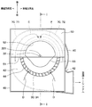
- FIG. 2 is a sectional view taken along line II-II of FIG. 1.
- FIG. 3 is a sectional view taken along line III-III in FIG. 1. It is a perspective view of the state which removed the inside and outside air box of the fan concerning a 1st embodiment. It is sectional drawing of the location corresponding to FIG. 3 in the air blower which concerns on 2nd Embodiment. It is sectional drawing of the location corresponding to FIG. 3 in the air blower which concerns on 3rd Embodiment. It is sectional drawing of the air blower which concerns on 4th Embodiment. It is sectional drawing of the VIII-VIII line of FIG. It is sectional drawing of the location corresponding to FIG. 3 in the fan of a comparative example.
- the blower 1 of the present embodiment is a one-sided suction type centrifugal blower that sucks air from only one side in the rotation axis direction of the impeller 30.
- the blower 1 is used for an inside / outside air two-layer flow type air conditioner for a vehicle capable of simultaneously blowing air while distinguishing between vehicle interior air (hereinafter referred to as inside air) and vehicle outside air (hereinafter referred to as outside air).
- the blower 1 includes an inside / outside air box 10, an impeller 30, a casing 40, a partition wall 46, a baffle plate 50 as a plate member, a separating cylinder 53, a guide rib 70, and the like. I have it.
- the inside / outside air box 10 is arranged above the blower 1.
- the inside / outside air box 10 has an outside air introduction port 11, a first inside air introduction port 12 and a second inside air introduction port 13 in this order from the front side of the vehicle. Outside air is introduced into the outside air inlet 11. Inside air is introduced into the first inside air inlet 12 and the second inside air inlet 13.
- a first switching door 14 and a second switching door 15 are provided inside the inside / outside air box 10.
- the first switching door 14 can selectively open and close the outside air introduction port 11 and the first inside air introduction port 12.
- the second switching door 15 can open and close the second inside air introduction port 13.
- the first switching door 14 and the second switching door 15 are, for example, rotary doors.
- the filter 20 is provided below the inside / outside air box 10 and collects foreign matter contained in the air introduced into the inside / outside air box 10 (that is, outside air and inside air).
- the filter 20 is configured, for example, by folding a filter material for dust removal having a predetermined air permeability into a pleated shape.
- the filter 20 is formed so that the pleats are folded in the direction in which the outside air introduction port 11, the first inside air introduction port 12, and the second inside air introduction port 13 are arranged (for example, the vehicle front-rear direction).
- the filter 20 has fold-shaped folds extending in a direction (eg, the vehicle width direction) orthogonal to the direction in which the outside air inlet 11, the first inside air inlet 12 and the second inside air inlet 13 are arranged.
- the inside / outside air box 10 and the filter 20 have a rectangular outer shape when viewed from above.
- the rectangular shape includes, in addition to a quadrangle, a shape in which a corner or corner of the quadrangle is chamfered with a curve or a straight line.
- the impeller 30 is a centrifugal fan that is rotated by the drive of the motor 31.
- the impeller 30 has a main plate 33 fixed to the shaft 32 of the motor 31 and a plurality of blades 34 fixed to the main plate 33.
- the impeller 30 is configured to suck in the air that has been introduced into the inside / outside air box 10 and passed through the filter 20 from one side in the rotation axis direction and blows out to the outside in the radial direction.
- a blade partition wall 35 is provided between the plurality of blades 34 for partitioning the wind flowing in the axially upper region of the blade 34 and the wind flowing in the axially lower region of the blade 34. There is.
- the casing 40 is a scroll casing that surrounds the outer side of the impeller 30 in the radial direction.
- the casing 40 forms a ventilation path 41 on the radially outer side of the impeller 30.
- the air passage 41 is mainly formed between the trailing edge 36 of the blade 34 of the impeller 30 and the inner wall of the casing 40.
- the air passage 41 has a shape in which the flow passage area gradually increases from the nose portion 42 provided on a part of the outer periphery thereof toward one side in the circumferential direction.
- a portion of the ventilation passage 41 having the largest flow passage area communicates with an air conditioning casing (not shown) included in the air conditioning device. Therefore, the air blown out from the ventilation passage 41 of the casing 40 is introduced into the air conditioning casing.
- an evaporator for adjusting the temperature and humidity of the air, a heater core, an air mix door, etc. are arranged in the air conditioning casing.
- the conditioned air, the temperature and humidity of which are adjusted in the air conditioning casing, is configured to be blown into the vehicle compartment from the face outlet, the foot outlet, the defroster outlet, and the like.
- An annular bell mouth 44 that forms an air inlet to the impeller 30 is provided on an end surface 43 of the casing 40 on the filter 20 side in the rotation axis direction of the impeller 30 (hereinafter referred to as the upper surface 43 of the casing 40).
- a mounting frame 45 for mounting the inside / outside air box 10 and the filter 20 described above is provided on the upper surface 43 of the casing 40. That is, the inside / outside air box 10 and the filter 20 are mounted on the mounting frame 45.
- the mounting frame 45 also has a rectangular outer shape when viewed from above.
- a partition wall 46 is provided inside the casing 40 to partition the ventilation passage 41 into one region in the axial direction of the impeller 30 and the other region in the axial direction of the impeller 30.
- the partition wall 46 is provided at a position corresponding to the blade partition wall 35 provided between the blades 34 of the impeller 30.
- a region of the ventilation passage 41 above the partition wall 46 will be referred to as an upper ventilation passage 47, and a region of the ventilation passage 41 below the partition wall 46 will be referred to as a lower ventilation passage 48.
- a baffle plate 50 as a plate member is provided between the casing 40 and the filter 20.
- the baffle plate 50 has a rectangular outer shape when viewed from above.
- the baffle plate 50 is provided with a predetermined gap between the upper surface 43 of the casing 40 and the bell mouth 44.
- the baffle plate 50 is provided so as to cover the upper surface 43 of the casing 40, the bell mouth 44, and a part of the region of the impeller 30 in the rotation axis direction. Specifically, the baffle plate 50 covers almost the half of the upper surface 43 of the casing 40, the bell mouth 44, and the region of the impeller 30 in the rotation axis direction.
- the second switching door 15 of the inside / outside air box 10 fully opens the second inside air inlet 13.
- it is provided at a position below the end portion 16 of the second switching door 15 on the filter 20 side.
- An air inlet portion 52 is formed in the air guide plate 50 at a location corresponding to a region on the radially inner side of the impeller 30. The air inlet 52 communicates with the flow path inside the separation cylinder 53.
- the separation cylinder 53 is formed in a cylindrical shape in a region inside the impeller 30 in the radial direction.
- the baffle plate 50 and the separation cylinder 53 are integrally formed and have a funnel shape.
- the separation cylinder 53 has a shape that extends from the air inlet portion 52 formed in the baffle plate 50 to the radial outside of the impeller 30.
- An end portion 54 of the separation cylinder 53 on the side opposite to the baffle plate 50 is located at a position corresponding to the blade partition wall 35 provided between the blades 34 of the impeller 30 (that is, the radial direction of the blade partition wall 35). Inside).
- a gap passage 60 is formed between the baffle plate 50 and the upper surface 43 of the casing 40 described above.
- the clearance passage 60 is formed on the outer side in the radial direction of the separation cylinder 53.
- a portion where the air passing through the filter 20 flows into the clearance passage 60 is referred to as an opening 61 of the clearance passage 60. That is, the opening 61 of the clearance passage 60 is formed between the outer edge 51 of the baffle plate 50, which is disposed on the rotary shaft 301 side of the impeller 30, and the upper surface 43 of the casing 40.
- the position of the opening 61 of the clearance passage 60 is indicated by a dashed line. This also applies to the drawings referred to in the second to fourth embodiments and the comparative example described later.
- a guide rib 70 is provided in a portion of the clearance passage 60 opposite to the opening 61.
- the guide rib 70 is a wall provided between the casing 40 and the baffle plate 50 so as to stand up in the direction along the rotating shaft 301 of the impeller 30.
- the guide rib 70 is formed integrally with the casing 40.
- the guide rib 70 is provided at least at a position corresponding to a corner of the baffle plate 50 so that the inner wall of the gap passage 60 has a curved shape.
- the guide ribs 70 guide the wind flowing through the clearance passage 60 in the circumferential direction of the bell mouth 44. Therefore, the guide rib 70 is formed in a curved shape along the bell mouth 44.
- the curvature of the curved shape of the guide rib 70 and the curvature of the bell mouth 44 may be different.
- the guide rib 70 of the present embodiment is integrally formed from one corner of the baffle plate 50 to the other corner.
- the guide rib 70 may have a portion 71 provided at one corner of the baffle plate 50 and a portion 72 provided at the other corner of the baffle plate 50 formed separately.
- a space 73 is formed between the guide rib 70 and the mounting frame 45. This makes it possible to reduce the thickness of the guide rib 70 and reduce the material cost.
- the air introduced into the inside / outside air box 10 and passing through the predetermined region of the filter 20 flows to the air guide plate 50, and the air inlet portion 52 formed in the air guide plate 50 moves to the separation cylinder 53. It flows through the inside and flows to the lower ventilation passage 48 via the impeller 30.
- the air introduced into the inside / outside air box 10 and passing through the other region of the filter 20 flows into the region excluding the baffle plate 50, passes through the outside of the separation cylinder 53 and the gap passage 60, and passes through the impeller 30. It flows to the upper ventilation passage 47.
- the predetermined area of the filter 20 is, for example, an area on the vehicle rear side of the position of the filter 20 where the end 16 of the second switching door 15 abuts.
- the other area of the filter 20 is, for example, an area on the vehicle front side of the position of the filter 20 with which the end portion 16 of the second switching door 15 abuts.
- FIG. 1 shows a state in which the first switching door 14 closes the first inside air introducing port 12 while opening the outside air introducing port 11, and the second switching door 15 opens the second inside air introducing port 13. ..
- the blower 1 can simultaneously inhale and blow out while separating the inside air and the outside air.
- the inside air introduced from the second inside air introduction port 13 passes through a region of the filter 20 substantially directly above the air guide plate 50, and then the air guide plate 50. Flows from the air inlet portion 52 formed in the inside of the separation cylinder 53 to the lower ventilation passage 48 via the impeller 30.
- the outside air introduced from the outside air introduction port 11 passes through the region of the filter 20 other than immediately above the air guide plate 50, and then the air guide plate 50 is removed. It passes through the outside of the separation cylinder 53 from the area, is sucked by the impeller 30, and flows into the upper ventilation passage 47.
- a part of the air flowing in the region excluding the baffle plate 50 is radially sucked into the impeller 30 as it is.
- arrows E and F in FIG. 2 and arrows G and H in FIG.
- the guide rib 70 is provided in the gap passage 60 at a position corresponding to the corner of the baffle plate 50.
- the guide rib 70 is provided so that the inner wall of the clearance passage 60 has a curved shape.
- the wind that has flowed into the gap passage 60 from the opening 61 on one side in the radial direction across the separation cylinder 53 is described on the left side of FIG.
- the part 71 guides the bell mouth 44 in the circumferential direction.
- the wind that has flowed into the clearance passage 60 from the opening 61 on the other side in the radial direction across the separation cylinder 53 is described in the guide rib 70 on the right side in FIG.
- the part 72 is guided in the circumferential direction of the bell mouth 44. Therefore, in the clearance passage 60, the winds collide with each other, and the two wind streams merge and are sucked into the impeller 30.
- the blower 1 of the present embodiment can reduce the pressure loss of the air sucked into the impeller 30 from the inside / outside air box 10 through the gap passage 60 and increase the blown amount of the blower 1. Further, in the blower 1 of the present embodiment, the clearance passage 60 between the baffle plate 50 and the upper surface 43 of the casing 40 can be lowered, and the size in the height direction can be reduced.
- the guide rib 70 of the second embodiment has a protrusion 74 at a portion of the clearance passage 60 opposite to the opening 61.
- the protruding portion 74 has a mountain shape that extends from the tip portion 75 provided on the bell mouth 44 side toward the mounting frame 45 side (that is, the outer wall side of the casing 40) in the vicinity thereof.
- a portion 71 provided on one corner side of the baffle plate 50, a portion 72 provided on the other corner side of the baffle plate 50, and a protrusion 74 are integrally formed. ing. That is, the guide rib 70 is integrally formed from one corner side of the baffle plate 50 to the other corner side.
- the tip 75 of the protrusion 74 of the guide rib 70 is provided so as to face the rotating shaft 301 of the impeller 30.
- the wind that has flowed into the gap passage 60 from the one opening 61 with the separation cylinder 53 sandwiched is guided to the left side of FIG.
- the curved portion 71 and the protrusion 74 described above guide the bell mouth 44 inward in the radial direction.
- the wind that has flowed into the gap passage 60 from the other opening 61 across the separation cylinder 53 is a curved portion 72 on the right side of FIG.
- the protrusion 74 guides the bell mouth 44 radially inward. Then, the two wind flows merge and are sucked into the impeller 30 from the radially inner side of the bell mouth 44.
- the guide rib 70 according to the second embodiment has the protrusion 74 that protrudes toward the bell mouth 44, so that the two wind flows flowing through the gap passage 60 can be easily guided to the inside of the bell mouth 44 in the radial direction. Is becoming Therefore, the blower 1 can reduce the pressure loss of the wind flowing through the clearance passage 60 and increase the blown amount of the blower 1.
- the tip end portion 75 of the protrusion 74 of the guide rib 70 is provided at a position displaced from the rotation shaft 301 of the impeller 30. Specifically, the tip end portion 75 of the protrusion portion 74 is provided on the side farther from the nose portion 42 with respect to the rotating shaft 301 of the impeller 30.
- the position of the tip end portion 75 of the protruding portion 74 is appropriately set in consideration of the wind flow that changes depending on the direction in which the impeller 30 rotates, the flow passage area of the left and right gap passages 60 of the separation cylinder 53, and the like. Therefore, the tip 75 of the protrusion 74 may be provided on the side closer to the nose 42 with respect to the rotating shaft 301 of the impeller 30.
- the wind that has flowed into the gap passage 60 from the one opening 61 with the separation cylinder 53 interposed therebetween is directed to the left side of FIG.
- the curved portion 71 and the protrusion 74 described above guide the bell mouth 44 inward in the radial direction.
- the wind that has flowed into the gap passage 60 from the other opening 61 across the separation cylinder 53 is a curved portion 72 on the right side of FIG.
- the protrusion 74 guides the bell mouth 44 radially inward. Then, the two wind flows merge and are sucked into the impeller 30 from the radially inner side of the bell mouth 44.
- the guide rib 70 of the third embodiment also has the protrusion 74 that protrudes toward the bell mouth 44, so that the two wind flows flowing through the gap passage 60 can be easily guided to the inside of the bell mouth 44 in the radial direction. Is becoming Therefore, the blower 1 can reduce the pressure loss of the wind flowing through the clearance passage 60 and increase the blown amount of the blower 1.
- a fourth embodiment will be described.
- the one-side suction type centrifugal blower that sucks air from only one side in the rotation axis direction of the impeller 30 has been described.
- a double-sided suction type centrifugal blower that sucks air from both sides of the impeller 30 in the rotation axis direction will be described.
- the blower 1 of the fourth embodiment is also used for an inside / outside air two-layer air-conditioning vehicle air conditioner capable of simultaneously blowing air while separating inside air and outside air.
- the blower 1 of the fourth embodiment includes an inside / outside air box 10, an impeller 30, a casing 40, a partition wall 46, a guide rib 70, and the like.
- the impeller 30 has an upper impeller 37 and a lower impeller 38.
- the upper impeller 37 is arranged in the upper ventilation passage 47
- the lower impeller 38 is arranged in the lower ventilation passage 48.
- the upper impeller 37 and the lower impeller 38 rotate integrally by driving the motor 31.
- a partition plate 49 is provided between the upper surface 43 of the casing 40 and the filter 20 to separate air that has passed through a predetermined region of the filter 20 from air that has passed through other regions. Therefore, as shown by the arrow M in FIG. 7, the air introduced into the inside / outside air box 10 and passing through the predetermined region of the filter 20 is sucked into the upper impeller 37 from the upper bell mouth 441 and is then introduced into the upper ventilation passage 47. Flowing.
- the casing 40 also has a communication passage 62 for sending the air that has passed through the other regions of the filter 20 to the lower impeller 38.
- the communication passage 62 has a vertical passage 63 extending substantially parallel to the rotating shaft 301 of the impeller 30 and a horizontal passage 64 extending in a direction intersecting with the rotating shaft 301 of the impeller 30.
- the lateral passage 64 corresponds to an example of the gap passage.
- the bottom plate 400 of the casing 40 forming the lateral passage 64 corresponds to an example of a plate-shaped member.
- a portion where air flows from the vertical passage 63 to the horizontal passage 64 is referred to as an opening 65 of the horizontal passage 64.
- the position of the opening 65 of the lateral passage 64 is indicated by a dashed line.
- a guide rib 70 is provided in a portion of the lateral passage 64 on the side opposite to the opening 65.
- the guide ribs 70 are provided at least at positions corresponding to the left and right corners of the bottom plate 400 of the casing 40 so that the inner wall of the lateral passage 64 has a curved shape.
- the guide rib 70 guides the wind flowing through the lateral passage 64 in the circumferential direction of the lower bell mouth 442.
- the air introduced into the inside / outside air box 10 and passing through the other region of the filter 20 flows from the vertical passage 63 to the horizontal passage 64 and from the lower bell mouth 442. It is sucked into the lower impeller 38 and flows into the lower ventilation passage 48.
- the wind flowing from the opening 65 of the lateral passage 64 through the lateral passage 64 is guided in the circumferential direction of the lower bell mouth 442 along the curved shape of the guide rib 70. Then, it is sucked into the lower impeller 38 from the inside of the lower bell mouth 442 in the radial direction.
- the wind flow in the lateral passage 64 becomes so-called lateral suction. Further, also in the fourth embodiment, by providing the guide rib 70 in the lateral passage 64, it is possible to prevent the stagnation of air from occurring in the lateral passage 64.
- the blower 1 of the fourth embodiment can also reduce the pressure loss of the air sucked into the impeller 30 from the inside / outside air box 10 through the vertical passage 63 and the horizontal passage 64, and increase the blown amount of the blower 1. it can.
- the shape, the positional relationship, etc., the shape thereof when referring to the shapes of the components and the like, the positional relationship, etc., unless otherwise explicitly stated and in principle, the shape, the positional relationship, etc., the shape thereof, It is not limited to the positional relationship or the like. That is, terms such as “upper”, “lower”, “left”, “right”, “vehicle front”, and “vehicle rear” in the description of each embodiment above are used for convenience in the description of each embodiment. The direction in which the blower is installed in the vehicle is not limited.
- blower 1 is described as being used in an inside / outside air two-layer air conditioner, but the present invention is not limited to this, and the blower 1 is used in a single-layer air conditioner. May be
- blower 1 for example, a plate-like member that obstructs the air flow to the bell mouth 44 is arranged, the height of the clearance passage 60 is low, and the impeller 30 may suck the wind radially. Applicable to difficult structures.
- blower 1 is described as a centrifugal blower, but the present invention is not limited to this, and the blower 1 may employ various types such as an axial blower.
- the guide rib 70 has been described as having a curved shape, but the present invention is not limited to this, and the guide rib 70 may have a planar shape, for example.
- the blower 1 has the same configuration, and by adjusting the positions of the first switching door 14 and the second switching door 15 of the inside / outside air box 10, only the outside air or only the inside air flows in both the upper ventilation passage 47 and the lower ventilation passage 48. It is also possible to do so, and it is also possible to make a state in which the mixed air of the inside air and the outside air flows.
- the inside / outside air box 10 has been described as having the outside air introduction port 11, the first inside air introduction port 12, and the second inside air introduction port 13 in this order from the vehicle front side. It is not limited to this.
- the outside air introduction port 11, the first inside air introduction port 12, and the second inside air introduction port 13 may be arranged in the vehicle width direction, or may be arranged sequentially from the vehicle rear side, or , May be arranged diagonally.
- the blower includes the inside / outside air box, the impeller, the casing, the plate-shaped member, and the guide rib.
- the air outside the vehicle compartment and the air inside the vehicle compartment are introduced into the inside / outside air box.
- the impeller rotates by driving a motor and sucks and blows out the air introduced into the inside / outside air box.
- the casing has a bell mouth that forms an air inlet to the impeller and forms a ventilation path that surrounds the outer side of the impeller in the radial direction.
- the plate-shaped member is provided with a predetermined gap with respect to the casing and the bell mouth, and is provided so as to cover at least a part of regions of the casing, the bell mouth, and the impeller in the rotation axis direction.
- This blower is configured such that the air that has flowed into the gap passage between the casing and the plate-shaped member flows in a direction that intersects the rotation axis of the impeller and is sucked into the impeller from the bell mouth.
- the guide rib is provided on the opposite side of the opening through which air flows into the clearance passage, and guides the wind flowing through the clearance passage in the circumferential direction of the bell mouth.
- the plate-shaped member has a rectangular shape when viewed from the axial direction of the impeller.
- the guide rib is provided at least at a position corresponding to a corner of the plate-shaped member so that the inner wall of the clearance passage has a curved shape. According to this, the wind flowing through the clearance passage is guided along the curved shape of the guide rib. Therefore, it is possible to prevent the stagnation of air from occurring at the corners of the plate-shaped member and reduce the pressure loss of the wind flowing through the gap passage.
- the guide rib is a wall provided between the casing and the plate-shaped member so as to stand up in the direction along the rotation axis of the impeller. According to this, the manufacturing cost can be reduced by forming the guide rib thin.
- the blower further includes a partition wall and a separating cylinder.
- the partition wall partitions the ventilation passage on the radially outer side of the impeller into one upper ventilation passage in the axial direction of the impeller and the other lower ventilation passage in the axial direction of the impeller.
- the separation cylinder has a shape that extends from the air inlet formed in the plate-shaped member to the radially outer side of the impeller through the radially inner side. Then, this blower is configured so that the air flowing from the inside / outside air box to the plate-shaped member flows from the air inlet portion through the inside of the separation cylinder to the lower ventilation passage via the impeller. Further, the air flowing from the inside / outside air box to the region excluding the plate-shaped member is configured to flow to the upper ventilation passage through the impeller and the outside of the separation cylinder and the gap passage.
- this blower is used for an inside / outside air two-layer air conditioner capable of simultaneously blowing air while separating the air inside the vehicle interior and the air outside the vehicle interior, and one of the impeller rotation axis directions. It is a one-sided suction type that inhales air from only.
- the guide rib has a protrusion that extends from the tip provided on the bell mouth side toward the outer wall of the casing.
- the wind flowing into the gap passage from one opening across the separation cylinder and the wind flowing into the gap passage from the other opening across the separation cylinder are respectively projected inside by the protrusions in the radial direction of the bell mouth. Be guided to. Then, the two wind flows merge and are sucked into the impeller from the radially inner side of the bell mouth. Therefore, this blower can reduce the pressure loss of the wind flowing through the clearance passage and increase the blown amount of the blower.
Landscapes
- Engineering & Computer Science (AREA)
- Mechanical Engineering (AREA)
- General Engineering & Computer Science (AREA)
- Chemical & Material Sciences (AREA)
- Combustion & Propulsion (AREA)
- Physics & Mathematics (AREA)
- Thermal Sciences (AREA)
- Structures Of Non-Positive Displacement Pumps (AREA)
- Air-Conditioning For Vehicles (AREA)
Abstract
羽根車(30)は、内外気箱(10)に導入された空気を吸入して吹き出す。ケーシング(40)は、ベルマウス(44)を有し、羽根車(30)の径方向外側を囲う通風路(41)を形成する。板状部材(50)は、ケーシング(40)およびベルマウス(44)に対して所定の隙間をあけて設けられ、ケーシング(40)、ベルマウス(44)および羽根車(30)の回転軸方向の領域の少なくとも一部を覆う。この送風機は、ケーシング(40)と板状部材(50)との間の隙間通路(60)へ流入した空気が羽根車(30)の回転軸(301)に対して交差する方向に流れ、ベルマウス(44)から羽根車(30)に吸い込まれるように構成されている。そして、案内リブ(70)は、その隙間通路(60)に空気が流入する開口部(61)とは反対側の部位に設けられ、隙間通路(60)を流れる風をベルマウス(44)の周方向に案内する。
Description
本出願は、2018年11月19日に出願された日本特許出願番号2018-216356号に基づくもので、ここにその記載内容が参照により組み入れられる。
本開示は、送風機に関し、特に、車両用空調装置に用いられる遠心送風機に関するものである。
従来、車室内空気と車室外空気を区分しつつ同時に送風可能な内外気二層流式の空調装置に用いられる送風機が知られている。
特許文献1には、そのような送風機として、羽根車の回転軸方向の一方のみから空気を吸入する片側吸込式の遠心送風機が記載されている。この送風機は、空気取り入れハウジング(以下、内外気箱という)から取り入れられた空気が、フィルタを経由して羽根車の内側に吸い込まれ、羽根車の径方向外側を囲うケーシング内の通風路に吹き出されるように構成されている。そのケーシング内の通風路は、仕切壁により、羽根車の軸方向の一方の上通風路と、軸方向の他方の下通風路とに仕切られている。そして、羽根車の径方向内側には、内外気箱から取り入れられた空気を上通風路と下通風路に分離して流すための分離筒が設けられている。分離筒は、羽根車とフィルタとの間の領域の一部に設けられる板状部材としての導風板に形成される空気入口部から羽根車の径方向内側を通って径方向外側に拡がる形状となっている。
特許文献1には、そのような送風機として、羽根車の回転軸方向の一方のみから空気を吸入する片側吸込式の遠心送風機が記載されている。この送風機は、空気取り入れハウジング(以下、内外気箱という)から取り入れられた空気が、フィルタを経由して羽根車の内側に吸い込まれ、羽根車の径方向外側を囲うケーシング内の通風路に吹き出されるように構成されている。そのケーシング内の通風路は、仕切壁により、羽根車の軸方向の一方の上通風路と、軸方向の他方の下通風路とに仕切られている。そして、羽根車の径方向内側には、内外気箱から取り入れられた空気を上通風路と下通風路に分離して流すための分離筒が設けられている。分離筒は、羽根車とフィルタとの間の領域の一部に設けられる板状部材としての導風板に形成される空気入口部から羽根車の径方向内側を通って径方向外側に拡がる形状となっている。
この構成により、内外気箱から導風板に流れる空気は、その導風板に設けられる空気入口部から分離筒の内側を通り、羽根車を介して下通風路に流れる。一方、内外気箱から導風板を除く領域に流れる空気の一部は、ケーシングの上面に設けられたベルマウスから羽根車に放射状に吸い込まれ、上通風路に流れる。また、導風板を除く部位に流れる空気の他の一部は、導風板とケーシングの上面との間に形成される流路(以下、隙間通路という)に流れた後、ベルマウスから羽根車に吸い込まれ、上通風路に流れる。
発明者らの詳細な検討の結果、特許文献1に記載の遠心送風機には、次の課題が見出された。即ち、特許文献1に記載の遠心送風機は、羽根車の回転軸方向から視て内外気箱および導風板が矩形状である。そのため、上述した導風板とケーシングの上面との間に形成される隙間通路の中で、導風板の角部に位置する部位とベルマウスの内周面との距離が遠くなる。これにより、隙間通路の中で導風板の角部近傍の風流れが悪化し、そこに風の淀みができることで、隙間通路を流れる風の圧力損失が大きくなるといった課題がある。
また、車両用空調装置に用いられる遠心送風機は、羽根車の回転軸方向の体格(すなわち、遠心送風機の高さ)を小型化する要求がある。そのため、遠心送風機の高さの小型化に伴い、導風板とケーシングの上面との間の隙間通路を低くした場合、隙間通路の風流れがさらに悪化する。その場合、隙間通路の中で導風板の角部近傍に形成される風の淀みにより、隙間通路を流れる風の圧力損失がより大きくなり、送風機の送風量が減少するといった課題がある。
また、車両用空調装置に用いられる遠心送風機は、羽根車の回転軸方向の体格(すなわち、遠心送風機の高さ)を小型化する要求がある。そのため、遠心送風機の高さの小型化に伴い、導風板とケーシングの上面との間の隙間通路を低くした場合、隙間通路の風流れがさらに悪化する。その場合、隙間通路の中で導風板の角部近傍に形成される風の淀みにより、隙間通路を流れる風の圧力損失がより大きくなり、送風機の送風量が減少するといった課題がある。
本開示は、圧力損失を低減し、送風量を増加することが可能な送風機を提供することを目的とする。
本開示の1つの観点によれば、送風機であって、
車室外空気および車室内空気が導入される内外気箱と、
モータの駆動により回転し、内外気箱に導入された空気を吸入して吹き出す羽根車と、
羽根車への空気の吸込口を形成するベルマウスを有し、羽根車の径方向外側に通風路を形成するケーシングと、
ケーシングおよびベルマウスに対して所定の隙間をあけて設けられ、ケーシング、ベルマウスおよび羽根車の回転軸方向の領域の少なくとも一部を覆うように設けられる板状部材と、を備え、
ケーシングと板状部材との間の隙間通路へ流入した空気が羽根車の回転軸に対して交差する方向に流れ、ベルマウスから羽根車に吸い込まれるように構成されており、
隙間通路に空気が流入する開口部とは反対側の部位に設けられ、隙間通路を流れる風をベルマウスの周方向に案内する案内リブを備える。
これによれば、隙間通路を流れる風は、案内リブによってベルマウスの周方向に案内され、ベルマウスの径方向内側から羽根車に吸い込まれる。そのため、隙間通路に空気の淀みが生じることが防がれる。また、隙間通路に空気が流入する開口部のうち、羽根車の回転軸を挟んで径方向の一方側から隙間通路に流入した風と、径方向の他方側から隙間通路に流入した風がそれぞれ案内リブによってベルマウスの周方向に案内される。そのため、隙間通路内でそれらの風同士がぶつかり、2つの風の流れが合流することで羽根車に吸い込まれ易くなる。したがって、この送風機は、内外気箱から隙間通路を通って羽根車に吸い込まれる空気の圧力損失を低減し、送風機の送風量を増加することができる。
なお、各構成要素等に付された括弧付きの参照符号は、その構成要素等と後述する実施形態に記載の具体的な構成要素等との対応関係の一例を示すものである。
以下、本開示の実施形態について図面を参照しつつ説明する。なお、以下の各実施形態相互において、互いに同一もしくは均等である部分には、同一符号を付し、その説明を省略する。
(第1実施形態)
第1実施形態について図面を参照しつつ説明する。本実施形態の送風機1は、羽根車30の回転軸方向の一方のみから空気を吸入する片側吸込式の遠心送風機である。この送風機1は、車室内空気(以下、内気という)と車室外空気(以下、外気という)を区分しつつ同時に送風可能な内外気二層流式の車両用空調装置に用いられるものである。
第1実施形態について図面を参照しつつ説明する。本実施形態の送風機1は、羽根車30の回転軸方向の一方のみから空気を吸入する片側吸込式の遠心送風機である。この送風機1は、車室内空気(以下、内気という)と車室外空気(以下、外気という)を区分しつつ同時に送風可能な内外気二層流式の車両用空調装置に用いられるものである。
図1~図4に示すように、送風機1は、内外気箱10、羽根車30、ケーシング40、仕切壁46、板状部材としての導風板50、分離筒53、および案内リブ70などを備えている。
内外気箱10は、送風機1の上部に配置されている。内外気箱10は、車両前方側から順に、外気導入口11、第1内気導入口12および第2内気導入口13を有している。外気導入口11には、外気が導入される。第1内気導入口12と第2内気導入口13には、内気が導入される。内外気箱10の内側には、第1切替ドア14と第2切替ドア15とが設けられている。第1切替ドア14は、外気導入口11と第1内気導入口12とを選択的に開閉可能である。第2切替ドア15は、第2内気導入口13を開閉可能である。第1切替ドア14と第2切替ドア15は、例えばロータリドアにより構成されている。
フィルタ20は、内外気箱10の下部に設けられ、内外気箱10に導入された空気(すなわち、外気および内気)に含まれる異物を捕集する。フィルタ20は、例えば、所定の通気性を有する除塵用濾材がひだ形状に折り曲げられて構成されている。フィルタ20は、外気導入口11と第1内気導入口12と第2内気導入口13が並ぶ方向(例えば、車両前後方向)に、ひだ形状が折り重なるように形成されている。換言すれば、フィルタ20は、外気導入口11と第1内気導入口12と第2内気導入口13が並ぶ方向に対し直交する方向(例えば、車幅方向)に、ひだ形状の折り目が延びている。
内外気箱10とフィルタ20は、上方から視て、その外形が矩形状に形成されている。なお、矩形状とは、四角形に加え、四角形の角部に曲線または直線の面取りがされた形状等も含んでいる。
内外気箱10とフィルタ20は、上方から視て、その外形が矩形状に形成されている。なお、矩形状とは、四角形に加え、四角形の角部に曲線または直線の面取りがされた形状等も含んでいる。
羽根車30は、モータ31の駆動により回転する遠心ファンである。羽根車30は、モータ31のシャフト32に固定される主板33、および、その主板33に固定される複数の翼34を有している。羽根車30は、内外気箱10に導入されてフィルタ20を通過した空気を、回転軸方向の一方の側から吸入し、径方向外側に吹き出すように構成されている。なお、複数の翼34同士の間には、翼34のうち軸方向上側の領域を流れる風と、翼34のうち軸方向下側の領域を流れる風とを仕切る翼仕切壁35が設けられている。
ケーシング40は、羽根車30の径方向外側を囲うスクロールケーシングである。ケーシング40は、羽根車30の径方向外側に通風路41を形成している。通風路41は、主に、羽根車30の翼34の後縁36とケーシング40の内壁との間に形成される。通風路41は、その外周の一部に設けられたノーズ部42から周方向の一方に向かい次第に流路面積が拡大する形状となっている。通風路41のうち流路面積が最大となる箇所は、空調装置が備える図示しない空調ケーシングに連通する。そのため、ケーシング40の通風路41から吹き出された空気は、その空調ケーシングに導入される。
なお、図示していないが、その空調ケーシング内には、空気の温度および湿度を調整するためのエバポレータ、ヒータコアおよびエアミックスドアなどが配置されている。そして、その空調ケーシング内で温度および湿度が調整された空調風は、フェイス吹出口、フット吹出口およびデフロスタ吹出口などから車室内に吹き出されるように構成されている。
ケーシング40のうち羽根車30の回転軸方向のフィルタ20側の端面43(以下、ケーシング40の上面43という)には、羽根車30への空気の吸込口を形成する環状のベルマウス44が設けられている。
また、ケーシング40の上面43には、上述した内外気箱10とフィルタ20を取り付けるための取付枠45が設けられている。すなわち、この取付枠45の上に、内外気箱10とフィルタ20が取り付けられる。なお、この取付枠45も、上方から視て、その外形が矩形状に形成されている。
また、ケーシング40の上面43には、上述した内外気箱10とフィルタ20を取り付けるための取付枠45が設けられている。すなわち、この取付枠45の上に、内外気箱10とフィルタ20が取り付けられる。なお、この取付枠45も、上方から視て、その外形が矩形状に形成されている。
また、ケーシング40の内側には、通風路41を、羽根車30の軸方向の一方の領域と、羽根車30の軸方向の他方の領域とに仕切る仕切壁46が設けられている。仕切壁46は、羽根車30の翼34同士の間に設けられる翼仕切壁35に対応する位置に設けられている。以下の説明では、通風路41のうち仕切壁46より上側の領域を上通風路47と呼び、通風路41のうち仕切壁46より下側の領域を下通風路48と呼ぶこととする。
ケーシング40とフィルタ20との間には、板状部材としての導風板50が設けられている。導風板50は、上方から視て、外形が矩形状に形成されている。導風板50は、ケーシング40の上面43およびベルマウス44に対して所定の隙間をあけて設けられている。また、導風板50は、ケーシング40の上面43、ベルマウス44および羽根車30の回転軸方向の領域の一部を覆うように設けられている。具体的には、導風板50は、ケーシング40の上面43、ベルマウス44および羽根車30の回転軸方向の領域のほぼ半分を覆っている。
図1に示すように、導風板50のうち羽根車30の回転軸301側に配置される外縁51は、内外気箱10の第2切替ドア15が第2内気導入口13を全開にした場合、第2切替ドア15のフィルタ20側の端部16の下側となる位置に設けられている。導風板50の中で羽根車30の径方向内側の領域に対応する箇所に空気入口部52が形成されている。空気入口部52は、分離筒53の内側の流路に連通している。
分離筒53は、羽根車30の径方向内側の領域において筒状に形成されている。導風板50と分離筒53とは一体に形成され、漏斗状に構成されている。そして、分離筒53は、導風板50に形成される空気入口部52から羽根車30の径方向内側を通って径方向外側に拡がる形状となっている。分離筒53のうち導風板50とは反対側の端部54は、羽根車30の翼34同士の間に設けられた翼仕切壁35に対応する位置(すなわち、翼仕切壁35の径方向内側)に設けられている。
上述した導風板50とケーシング40の上面43との間には、隙間通路60が形成されている。隙間通路60は、分離筒53の径方向外側に形成されている。この隙間通路60には、内外気箱10からフィルタ20を通過して、導風板50を除く領域に流れる空気の一部が流入する。本実施形態では、フィルタ20を通過した空気がその隙間通路60に流入する箇所を、隙間通路60の開口部61ということとする。すなわち、隙間通路60の開口部61は、導風板50のうち羽根車30の回転軸301側に配置される外縁51と、ケーシング40の上面43との間に形成される。
なお、図3では、隙間通路60の開口部61の位置を、一点鎖線で示している。なお、このことは、後述する第2~第4実施形態および比較例で参照する図でも同様である。
なお、図3では、隙間通路60の開口部61の位置を、一点鎖線で示している。なお、このことは、後述する第2~第4実施形態および比較例で参照する図でも同様である。
隙間通路60の中で、開口部61とは反対側の部位には、案内リブ70が設けられている。案内リブ70は、ケーシング40と導風板50と間で、羽根車30の回転軸301に沿う方向に立ち上がるように設けられる壁である。案内リブ70は、ケーシング40と一体に形成されている。
案内リブ70は、少なくとも導風板50の角部に対応する位置に、隙間通路60の内壁が曲面形状となるように設けられている。案内リブ70は、隙間通路60を流れる風をベルマウス44の周方向に案内するものである。したがって、案内リブ70は、ベルマウス44に沿うような曲面形状に形成されている。なお、案内リブ70の曲面形状の曲率と、ベルマウス44の曲率とは異なっていてもよい。
本実施形態の案内リブ70は、導風板50の一方の角部から他方の角部に亘り一体に形成されている。なお、案内リブ70は、導風板50の一方の角部に設けられる部位71と、導風板50の他方の角部に設けられる部位72とが別個に形成されていてもよい。
案内リブ70と取付枠45との間には空間73が形成されている。これにより、案内リブ70の肉厚を薄くして、材料コストを低減することができる。
上述した構成において、内外気箱10に導入されてフィルタ20の所定の領域を通過した空気は、導風板50に流れ、その導風板50に形成された空気入口部52から分離筒53の内側を通り、羽根車30を介して下通風路48に流れる。一方、内外気箱10に導入されてフィルタ20の他の領域を通過した空気は、導風板50を除く領域に流れ、分離筒53の外側および隙間通路60を通り、羽根車30を介して上通風路47に流れる。なお、フィルタ20の所定の領域とは、例えば、フィルタ20のうち第2切替ドア15の端部16が当接する位置よりも車両後方側の領域である。また、フィルタ20の他の領域とは、例えば、フィルタ20のうち第2切替ドア15の端部16が当接する位置よりも車両前方側の領域である。
図1では、第1切替ドア14が外気導入口11を開放しつつ第1内気導入口12を閉塞し、且つ、第2切替ドア15が第2内気導入口13を開放した状態を示している。このような状態で、送風機1は、内気と外気とを区分しつつ同時に吸入して吹き出すことが可能である。
具体的には、図1の矢印Aに示すように、第2内気導入口13から導入される内気は、フィルタ20のうち導風板50の略直上の領域を通過した後、導風板50に形成される空気入口部52から分離筒53の内側を通り、羽根車30を介して下通風路48に流れる。
一方、図1の矢印B、Cに示すように、外気導入口11から導入される外気は、フィルタ20のうち導風板50の略直上を除く領域を通過した後、導風板50を除く領域から分離筒53の外側を通り、羽根車30に吸い込まれ、上通風路47に流れる。
詳細には、図1の矢印Bおよび図2の矢印Dに示すように、導風板50を除く領域を流れる空気の一部は、そのまま羽根車30に放射状に吸い込まれる。また、図1の矢印C、図2の矢印E、F、および図3の矢印G、Hに示すように、導風板50を除く領域を流れる空気の他の一部は、分離筒53の外側左右の開口部61から隙間通路60に流入し、ベルマウス44から羽根車30に吸い込まれる。なお、本明細書では、隙間通路60に流入した空気が羽根車30の回転軸301に対して交差する方向に流れつつ羽根車30に吸い込まれる風流れを「横吸い」と呼ぶ。すなわち、この送風機1は、導風板50を除く領域を流れる空気は、その一部が羽根車30に放射状に吸い込まれ、他の一部が横吸いとなって隙間通路60を流れて羽根車30に吸い込まれる。
詳細には、図1の矢印Bおよび図2の矢印Dに示すように、導風板50を除く領域を流れる空気の一部は、そのまま羽根車30に放射状に吸い込まれる。また、図1の矢印C、図2の矢印E、F、および図3の矢印G、Hに示すように、導風板50を除く領域を流れる空気の他の一部は、分離筒53の外側左右の開口部61から隙間通路60に流入し、ベルマウス44から羽根車30に吸い込まれる。なお、本明細書では、隙間通路60に流入した空気が羽根車30の回転軸301に対して交差する方向に流れつつ羽根車30に吸い込まれる風流れを「横吸い」と呼ぶ。すなわち、この送風機1は、導風板50を除く領域を流れる空気は、その一部が羽根車30に放射状に吸い込まれ、他の一部が横吸いとなって隙間通路60を流れて羽根車30に吸い込まれる。
ここで、図9に示した比較例の送風機のように、隙間通路60の中に案内リブ70が設けられていない場合、横吸いとなる隙間通路60の風流れが悪化し、隙間通路60のうち導風板50の角部近傍に風の淀みが発生することがある。なお、図9では、隙間通路60の中で風の淀みが発生する箇所を、符号Sを付した破線で示している。その場合、内外気箱10から隙間通路60を通って羽根車30に吸い込まれる空気の圧力損失が増大し、送風機1の送風量が減少するといった問題が生じる。
そのような比較例に対し、本実施形態では、隙間通路60の中で導風板50の角部に対応する位置に案内リブ70が設けられている。案内リブ70は、隙間通路60の内壁が曲面形状となるように設けられている。これにより、隙間通路60を流れる風は、案内リブ70の曲面形状に沿ってベルマウス44の周方向に案内され、ベルマウス44の径方向内側から羽根車30に吸い込まれる。そのため、隙間通路60の中に空気の淀みが生じることが防がれる。
また、図3の矢印Gに示したように、分離筒53を挟んで径方向の一方側の開口部61から隙間通路60に流入した風は、案内リブ70のうち図3の左側に記載の部位71によってベルマウス44の周方向に案内される。一方、図3の矢印Hに示したように、分離筒53を挟んで径方向の他方側の開口部61から隙間通路60に流入した風は、案内リブ70のうち図3の右側に記載の部位72によってベルマウス44の周方向に案内される。そのため、隙間通路60内で、それらの風同士がぶつかり、2つの風の流れが合流して羽根車30に吸い込まれる。これにより、隙間通路60を流れる風が層流化され、羽根車30に吸い込まれ易くなる。したがって、本実施形態の送風機1は、内外気箱10から隙間通路60を通って羽根車30に吸い込まれる空気の圧力損失を低減し、送風機1の送風量を増加することができる。さらに、本実施形態の送風機1は、導風板50とケーシング40の上面43との間の隙間通路60を低くすることが可能であり、高さ方向の体格の小型化することができる。
(第2および第3実施形態)
第2および第3実施形態について説明する。第2および第3実施形態は、第1実施形態に対して案内リブ70の構成を変更したものであり、その他については第1実施形態と同様であるため、第1実施形態と異なる部分についてのみ説明する。
第2および第3実施形態について説明する。第2および第3実施形態は、第1実施形態に対して案内リブ70の構成を変更したものであり、その他については第1実施形態と同様であるため、第1実施形態と異なる部分についてのみ説明する。
(第2実施形態)
図5に示すように、第2実施形態の案内リブ70は、隙間通路60の中で開口部61とは反対側の部位に突起部74を有している。突起部74は、ベルマウス44側に設けられた先端部75からその近傍の取付枠45側(すなわち、ケーシング40の外壁側)に向かって拡がるような山形状となっている。そして、案内リブ70は、導風板50の一方の角部側に設けられる部位71と、導風板50の他方の角部側に設けられる部位72と、突起部74とが一体に形成されている。すなわち、案内リブ70は、導風板50の一方の角部側から他方の角部側に亘り一体に形成されている。なお、第2実施形態では、案内リブ70の有する突起部74の先端部75は、羽根車30の回転軸301に向くように設けられている。
図5に示すように、第2実施形態の案内リブ70は、隙間通路60の中で開口部61とは反対側の部位に突起部74を有している。突起部74は、ベルマウス44側に設けられた先端部75からその近傍の取付枠45側(すなわち、ケーシング40の外壁側)に向かって拡がるような山形状となっている。そして、案内リブ70は、導風板50の一方の角部側に設けられる部位71と、導風板50の他方の角部側に設けられる部位72と、突起部74とが一体に形成されている。すなわち、案内リブ70は、導風板50の一方の角部側から他方の角部側に亘り一体に形成されている。なお、第2実施形態では、案内リブ70の有する突起部74の先端部75は、羽根車30の回転軸301に向くように設けられている。
以上説明した第2実施形態では、図5の矢印Iに示すように、分離筒53を挟んで一方の開口部61から隙間通路60に流入した風は、案内リブ70のうち図5の左側に記載の曲面形状の部位71と突起部74によってベルマウス44の径方向内側へ案内される。一方、図5の矢印Jに示すように、分離筒53を挟んで他方の開口部61から隙間通路60に流入した風は、案内リブ70のうち図5の右側に記載の曲面形状の部位72と突起部74によってベルマウス44の径方向内側へ案内される。そして、その2つの風の流れは合流してベルマウス44の径方向内側から羽根車30に吸い込まれる。すなわち、第2実施形態の案内リブ70は、ベルマウス44側に突出する突起部74を有することで、隙間通路60を流れる2つの風の流れをベルマウス44の径方向内側へ導きやすい形状となっている。したがって、この送風機1は、隙間通路60を流れる風の圧力損失を低減し、送風機1の送風量を増加することができる。
(第3実施形態)
図6に示すように、第3実施形態では、案内リブ70の有する突起部74の先端部75は、羽根車30の回転軸301に対してずれた位置に設けられている。具体的には、突起部74の先端部75は、羽根車30の回転軸301に対し、ノーズ部42から遠い側に設けられている。なお、突起部74の先端部75の位置は、羽根車30が回転する方向や、分離筒53の左右の隙間通路60の流路面積などにより変化する風流れを考慮して適宜設定される。そのため、突起部74の先端部75は、羽根車30の回転軸301に対し、ノーズ部42から近い側に設けられる場合もある。
図6に示すように、第3実施形態では、案内リブ70の有する突起部74の先端部75は、羽根車30の回転軸301に対してずれた位置に設けられている。具体的には、突起部74の先端部75は、羽根車30の回転軸301に対し、ノーズ部42から遠い側に設けられている。なお、突起部74の先端部75の位置は、羽根車30が回転する方向や、分離筒53の左右の隙間通路60の流路面積などにより変化する風流れを考慮して適宜設定される。そのため、突起部74の先端部75は、羽根車30の回転軸301に対し、ノーズ部42から近い側に設けられる場合もある。
以上説明した第3実施形態では、図6の矢印Kに示すように、分離筒53を挟んで一方の開口部61から隙間通路60に流入した風は、案内リブ70のうち図6の左側に記載の曲面形状の部位71と突起部74によってベルマウス44の径方向内側へ案内される。一方、図6の矢印Lに示すように、分離筒53を挟んで他方の開口部61から隙間通路60に流入した風は、案内リブ70のうち図6の右側に記載の曲面形状の部位72と突起部74によってベルマウス44の径方向内側へ案内される。そして、その2つの風の流れは合流してベルマウス44の径方向内側から羽根車30に吸い込まれる。すなわち、第3実施形態の案内リブ70も、ベルマウス44側に突出する突起部74を有することで、隙間通路60を流れる2つの風の流れをベルマウス44の径方向内側へ導きやすい形状となっている。したがって、この送風機1は、隙間通路60を流れる風の圧力損失を低減し、送風機1の送風量を増加することができる。
(第4実施形態)
第4実施形態について説明する。上述した第1~第3実施形態では、羽根車30の回転軸方向の一方のみから空気を吸入する片側吸込式の遠心送風機について説明した。これに対し、第4実施形態では、羽根車30の回転軸方向の両側からそれぞれ空気を吸入する両側吸込式の遠心送風機について説明する。なお、第4実施形態の送風機1も、内気と外気とを区分しつつ同時に送風可能な内外気二層流式の車両用空調装置に用いられるものである。
第4実施形態について説明する。上述した第1~第3実施形態では、羽根車30の回転軸方向の一方のみから空気を吸入する片側吸込式の遠心送風機について説明した。これに対し、第4実施形態では、羽根車30の回転軸方向の両側からそれぞれ空気を吸入する両側吸込式の遠心送風機について説明する。なお、第4実施形態の送風機1も、内気と外気とを区分しつつ同時に送風可能な内外気二層流式の車両用空調装置に用いられるものである。
図7および図8に示すように、第4実施形態の送風機1は、内外気箱10、羽根車30、ケーシング40、仕切壁46、および案内リブ70などを備えている。
羽根車30は、上羽根車37と下羽根車38とを有している。上羽根車37は上通風路47に配置され、下羽根車38は下通風路48に配置されている。なお、上羽根車37と下羽根車38は、モータ31の駆動により一体で回転する。
羽根車30は、上羽根車37と下羽根車38とを有している。上羽根車37は上通風路47に配置され、下羽根車38は下通風路48に配置されている。なお、上羽根車37と下羽根車38は、モータ31の駆動により一体で回転する。
ケーシング40の上面43とフィルタ20との間には、フィルタ20の所定の領域を通過した空気と、他の領域を通過した空気とを区分するための仕切板49が設けられている。そのため、図7の矢印Mに示すように、内外気箱10に導入されてフィルタ20の所定の領域を通過した空気は、上ベルマウス441から上羽根車37に吸い込まれ、上通風路47に流れる。
また、ケーシング40は、フィルタ20の他の領域を通過した空気を下羽根車38に送るための連絡通路62を有している。連絡通路62は、羽根車30の回転軸301とほぼ平行に延びる縦通路63と、羽根車30の回転軸301に対して交差する方向に延びる横通路64を有している。第4実施形態では、その横通路64が、隙間通路の一例に相当する。そして、その横通路64を形成するケーシング40の底板400が、板状部材の一例に相当する。
第4実施形態では、縦通路63から横通路64に空気が流入する部位を、横通路64の開口部65ということとする。図7および図8では、横通路64の開口部65の位置を、一点鎖線で示している。
図8に示すように、横通路64の中で、開口部65とは反対側の部位には、案内リブ70が設けられている。案内リブ70は、少なくともケーシング40の底板400の左右の角部に対応する位置に、横通路64の内壁が曲面形状となるように設けられている。案内リブ70は、横通路64を流れる風を下ベルマウス442の周方向に案内するものである。
図8に示すように、横通路64の中で、開口部65とは反対側の部位には、案内リブ70が設けられている。案内リブ70は、少なくともケーシング40の底板400の左右の角部に対応する位置に、横通路64の内壁が曲面形状となるように設けられている。案内リブ70は、横通路64を流れる風を下ベルマウス442の周方向に案内するものである。
上述した構成において、図7の矢印Nに示すように、内外気箱10に導入されてフィルタ20の他の領域を通過した空気は、縦通路63から横通路64に流れ、下ベルマウス442から下羽根車38に吸い込まれて下通風路48に流れる。詳細には、図8の矢印O、Pに示すように、横通路64の開口部65から横通路64を流れる風は、案内リブ70の曲面形状に沿って下ベルマウス442の周方向に案内され、下ベルマウス442の径方向内側から下羽根車38に吸い込まれる。そのため、第4実施形態においても、横通路64の風流れは、いわゆる横吸いとなる。そして、第4実施形態でも、横通路64の中に案内リブ70を設けることで、横通路64の中に空気の淀みが生じることが防がれる。
また、図8の矢印O、Pに示すように、横通路64の開口部65の左右から横通路64内に流入した風はそれぞれ、案内リブ70の左右の部位71、72によって下ベルマウス442の周方向に案内される。そして、横通路64内で、それらの風同士がぶつかり、合流して羽根車30に吸い込まれる。これにより、横通路64を流れる風が層流化され、羽根車30に吸い込まれ易くなる。したがって、第4実施形態の送風機1も、内外気箱10から縦通路63および横通路64を通って羽根車30に吸い込まれる空気の圧力損失を低減し、送風機1の送風量を増加することができる。
(他の実施形態)
本開示は上記した実施形態に限定されるものではなく、適宜変更が可能である。また、上記各実施形態は、互いに無関係なものではなく、組み合わせが明らかに不可な場合を除き、適宜組み合わせが可能である。また、上記各実施形態において、実施形態を構成する要素は、特に必須であると明示した場合および原理的に明らかに必須であると考えられる場合等を除き、必ずしも必須のものではないことは言うまでもない。また、上記各実施形態において、実施形態の構成要素の個数、数値、量、範囲等の数値が言及されている場合、特に必須であると明示した場合および原理的に明らかに特定の数に限定される場合等を除き、その特定の数に限定されるものではない。また、上記各実施形態において、構成要素等の形状、位置関係等に言及するときは、特に明示した場合および原理的に特定の形状、位置関係等に限定される場合等を除き、その形状、位置関係等に限定されるものではない。すなわち、上記各実施形態の説明において「上」、「下」、「左」、「右」、「車両前方」および「車両後方」等の用語は各実施形態の説明において便宜上用いたものであり、送風機が車両等に設置される方向を限定したものではない。
本開示は上記した実施形態に限定されるものではなく、適宜変更が可能である。また、上記各実施形態は、互いに無関係なものではなく、組み合わせが明らかに不可な場合を除き、適宜組み合わせが可能である。また、上記各実施形態において、実施形態を構成する要素は、特に必須であると明示した場合および原理的に明らかに必須であると考えられる場合等を除き、必ずしも必須のものではないことは言うまでもない。また、上記各実施形態において、実施形態の構成要素の個数、数値、量、範囲等の数値が言及されている場合、特に必須であると明示した場合および原理的に明らかに特定の数に限定される場合等を除き、その特定の数に限定されるものではない。また、上記各実施形態において、構成要素等の形状、位置関係等に言及するときは、特に明示した場合および原理的に特定の形状、位置関係等に限定される場合等を除き、その形状、位置関係等に限定されるものではない。すなわち、上記各実施形態の説明において「上」、「下」、「左」、「右」、「車両前方」および「車両後方」等の用語は各実施形態の説明において便宜上用いたものであり、送風機が車両等に設置される方向を限定したものではない。
(1)上述した各実施形態では、送風機1は、内外気二層式の空調装置に用いられるものとして説明したが、これに限らず、送風機1は、単層式の空調装置に用いられるものであってもよい。
(2)送風機1は、例えば、ベルマウス44への風流れを阻害するような板状部材が配置され、且つ、隙間通路60の高さが低く、羽根車30が放射状に風を吸い込むことが困難な構造ものに適用できる。
(3)上述した各実施形態では、送風機1を遠心送風機として説明したが、これに限らず、送風機1は、例えば軸流送風機など、種々の方式のものを採用してもよい。
(4)上述した各実施形態では、案内リブ70を曲面形状ものとして説明したが、これに限らず、案内リブ70は例えば平面形状としてもよい。
(5)上述した各実施形態の説明では、上通風路47に外気が流れ、下通風路48に内気が流れる状態について説明したが、これに限られるものではない。送風機1は、同構成で内外気箱10の第1切替ドア14と第2切替ドア15の位置調整により、上通風路47と下通風路48の両方に、外気のみ又は内気のみが流れる状態にすることも可能であり、内気と外気とを混合した空気が流れる状態にすることも可能である。
(6)上述した各実施形態の説明では、内外気箱10は、車両前方側から順に、外気導入口11、第1内気導入口12および第2内気導入口13を有するものとして説明したが、これに限られるものではない。内外気箱10は、外気導入口11、第1内気導入口12および第2内気導入口13を、車幅方向に配置してもよく、または、車両後方側から順に配置してもよく、または、斜めに配置してもよい。
(まとめ)
上述の実施形態の一部または全部で示された第1の観点によれば、送風機は、内外気箱、羽根車、ケーシング、板状部材および案内リブを備える。内外気箱は、車室外空気および車室内空気が導入される。羽根車は、モータの駆動により回転し、内外気箱に導入された空気を吸入して吹き出す。ケーシングは、羽根車への空気の吸込口を形成するベルマウスを有し、羽根車の径方向外側を囲う通風路を形成する。板状部材は、ケーシングおよびベルマウスに対して所定の隙間をあけて設けられ、ケーシング、ベルマウスおよび羽根車の回転軸方向の領域の少なくとも一部を覆うように設けられる。この送風機は、ケーシングと板状部材との間の隙間通路へ流入した空気が羽根車の回転軸に対して交差する方向に流れ、ベルマウスから羽根車に吸い込まれるように構成されている。そして、案内リブは、その隙間通路に空気が流入する開口部とは反対側の部位に設けられ、隙間通路を流れる風をベルマウスの周方向に案内する。
上述の実施形態の一部または全部で示された第1の観点によれば、送風機は、内外気箱、羽根車、ケーシング、板状部材および案内リブを備える。内外気箱は、車室外空気および車室内空気が導入される。羽根車は、モータの駆動により回転し、内外気箱に導入された空気を吸入して吹き出す。ケーシングは、羽根車への空気の吸込口を形成するベルマウスを有し、羽根車の径方向外側を囲う通風路を形成する。板状部材は、ケーシングおよびベルマウスに対して所定の隙間をあけて設けられ、ケーシング、ベルマウスおよび羽根車の回転軸方向の領域の少なくとも一部を覆うように設けられる。この送風機は、ケーシングと板状部材との間の隙間通路へ流入した空気が羽根車の回転軸に対して交差する方向に流れ、ベルマウスから羽根車に吸い込まれるように構成されている。そして、案内リブは、その隙間通路に空気が流入する開口部とは反対側の部位に設けられ、隙間通路を流れる風をベルマウスの周方向に案内する。
第2の観点によれば、板状部材は、羽根車の軸方向から視て矩形状である。案内リブは、少なくとも板状部材の角部に対応する位置に、隙間通路の内壁が曲面形状となるように設けられている。
これによれば、隙間通路を流れる風は、案内リブの曲面形状に沿って案内される。したがって、板状部材の角部に空気の淀みが生じることを防ぐと共に、隙間通路を流れる風の圧力損失を低減することができる。
これによれば、隙間通路を流れる風は、案内リブの曲面形状に沿って案内される。したがって、板状部材の角部に空気の淀みが生じることを防ぐと共に、隙間通路を流れる風の圧力損失を低減することができる。
第3の観点によれば、案内リブは、ケーシングと板状部材と間で、羽根車の回転軸に沿う方向に立ち上がるように設けられる壁である。
これによれば、案内リブの肉厚を薄く形成することで、製造上のコストを低減することができる。
これによれば、案内リブの肉厚を薄く形成することで、製造上のコストを低減することができる。
第4の観点によれば、送風機は、仕切壁および分離筒をさらに備える。仕切壁は、羽根車の径方向外側の通風路を羽根車の軸方向の一方の上通風路と軸方向の他方の下通風路とに仕切る。分離筒は、板状部材に形成される空気入口部から羽根車の径方向内側を通って径方向外側に拡がる形状である。そして、この送風機は、内外気箱から板状部材に流れる空気が、空気入口部から分離筒の内側を通り羽根車を介して下通風路に流れるように構成されている。また、内外気箱から板状部材を除く領域に流れる空気が、分離筒の外側および隙間通路を通り羽根車を介して上通風路に流れるように構成されている。
これによれば、この送風機は、車室内空気と車室外空気を区分しつつ同時に送風可能な内外気二層流式の空調装置に用いられるものであり、且つ、羽根車の回転軸方向の一方のみから空気を吸入する片側吸込式である。
第5の観点によれば、案内リブは、ベルマウス側に設けられる先端部からケーシングの外壁側に向かって拡がる形状の突起部を有している。
これによれば、分離筒を挟んで一方の開口部から隙間通路に流入した風と、分離筒を挟んで他方の開口部から隙間通路に流入した風はそれぞれ突起部によってベルマウスの径方向内側へ案内される。そして、その2つの風の流れは合流してベルマウスの径方向内側から羽根車に吸い込まれる。したがって、この送風機は、隙間通路を流れる風の圧力損失を低減し、送風機の送風量を増加することができる。
Claims (5)
- 送風機であって、
車室外空気および車室内空気が導入される内外気箱(10)と、
モータ(31)の駆動により回転し、前記内外気箱に導入された空気を吸入して吹き出す羽根車(30)と、
前記羽根車への空気の吸込口を形成するベルマウス(44、442)を有し、前記羽根車の径方向外側に通風路(41)を形成するケーシング(40)と、
前記ケーシングおよび前記ベルマウスに対して所定の隙間をあけて設けられ、前記ケーシング、前記ベルマウスおよび前記羽根車の回転軸方向の領域の少なくとも一部を覆うように設けられる板状部材(50、400)と、を備え、
前記ケーシングと前記板状部材との間の隙間通路(60、64)へ流入した空気が前記羽根車の回転軸(301)に対して交差する方向に流れ、前記ベルマウスから前記羽根車に吸い込まれるように構成されており、
前記隙間通路に空気が流入する開口部(61、65)とは反対側の部位に設けられ、前記隙間通路を流れる風を前記ベルマウスの周方向に案内する案内リブ(70)を備える送風機。 - 前記板状部材は、前記羽根車の軸方向から視て矩形状であり、
前記案内リブは、少なくとも前記板状部材の角部に対応する位置に、前記隙間通路の内壁が曲面形状となるように設けられている、請求項1に記載の送風機。 - 前記案内リブは、前記ケーシングと前記板状部材と間で、前記羽根車の回転軸に沿う方向に立ち上がるように設けられる壁である、請求項1または2に記載の送風機。
- 前記羽根車の径方向外側の前記通風路を前記羽根車の軸方向の一方の上通風路(47)と軸方向の他方の下通風路(48)とに仕切る仕切壁(46)と、
前記板状部材(50)に形成される空気入口部(52)から前記羽根車の径方向内側を通って径方向外側に拡がる形状の分離筒(53)と、をさらに備え、
前記内外気箱から前記板状部材に流れる空気は、前記空気入口部から前記分離筒の内側を通り前記羽根車を介して前記下通風路に流れ、
前記内外気箱から前記板状部材を除く領域に流れる空気は、前記分離筒の外側および前記隙間通路を通り前記羽根車を介して前記上通風路に流れるように構成されている、請求項1ないし3のいずれか1つに記載の送風機。 - 前記案内リブは、前記ベルマウス側に設けられる先端部(75)から前記ベルマウスに対し径方向外側に離れるに従い次第に拡がる形状の突起部(74)を有している、請求項1ないし4のいずれか1つに記載の送風機。
Priority Applications (2)
| Application Number | Priority Date | Filing Date | Title |
|---|---|---|---|
| CN201980076478.3A CN113167293B (zh) | 2018-11-19 | 2019-10-03 | 送风机 |
| US17/215,659 US11852362B2 (en) | 2018-11-19 | 2021-03-29 | Blower |
Applications Claiming Priority (2)
| Application Number | Priority Date | Filing Date | Title |
|---|---|---|---|
| JP2018-216356 | 2018-11-19 | ||
| JP2018216356A JP7070361B2 (ja) | 2018-11-19 | 2018-11-19 | 送風機 |
Related Child Applications (1)
| Application Number | Title | Priority Date | Filing Date |
|---|---|---|---|
| US17/215,659 Continuation US11852362B2 (en) | 2018-11-19 | 2021-03-29 | Blower |
Publications (1)
| Publication Number | Publication Date |
|---|---|
| WO2020105294A1 true WO2020105294A1 (ja) | 2020-05-28 |
Family
ID=70774156
Family Applications (1)
| Application Number | Title | Priority Date | Filing Date |
|---|---|---|---|
| PCT/JP2019/039152 WO2020105294A1 (ja) | 2018-11-19 | 2019-10-03 | 送風機 |
Country Status (4)
| Country | Link |
|---|---|
| US (1) | US11852362B2 (ja) |
| JP (1) | JP7070361B2 (ja) |
| CN (1) | CN113167293B (ja) |
| WO (1) | WO2020105294A1 (ja) |
Families Citing this family (1)
| Publication number | Priority date | Publication date | Assignee | Title |
|---|---|---|---|---|
| JP7159804B2 (ja) * | 2018-11-19 | 2022-10-25 | 株式会社デンソー | 遠心式送風機 |
Citations (2)
| Publication number | Priority date | Publication date | Assignee | Title |
|---|---|---|---|---|
| JP2018035792A (ja) * | 2016-09-02 | 2018-03-08 | 株式会社ヴァレオジャパン | 車両用空調装置のための遠心送風機 |
| WO2018074339A1 (ja) * | 2016-10-18 | 2018-04-26 | 株式会社ヴァレオジャパン | 遠心送風機 |
Family Cites Families (4)
| Publication number | Priority date | Publication date | Assignee | Title |
|---|---|---|---|---|
| EP1574718A4 (en) * | 2002-12-16 | 2011-01-26 | Daikin Ind Ltd | CENTRIFUGAL FAN AND AIR CONDITIONING THEREWITH |
| MY162288A (en) * | 2010-03-15 | 2017-05-31 | Sharp Kk | Fan, molding die, and fluid feeder |
| WO2011114410A1 (ja) * | 2010-03-15 | 2011-09-22 | 株式会社ヴァレオジャパン | 車両用空調ユニット |
| JP6111914B2 (ja) * | 2013-07-11 | 2017-04-12 | 株式会社デンソー | 送風機 |
-
2018
- 2018-11-19 JP JP2018216356A patent/JP7070361B2/ja active Active
-
2019
- 2019-10-03 CN CN201980076478.3A patent/CN113167293B/zh active Active
- 2019-10-03 WO PCT/JP2019/039152 patent/WO2020105294A1/ja active Application Filing
-
2021
- 2021-03-29 US US17/215,659 patent/US11852362B2/en active Active
Patent Citations (2)
| Publication number | Priority date | Publication date | Assignee | Title |
|---|---|---|---|---|
| JP2018035792A (ja) * | 2016-09-02 | 2018-03-08 | 株式会社ヴァレオジャパン | 車両用空調装置のための遠心送風機 |
| WO2018074339A1 (ja) * | 2016-10-18 | 2018-04-26 | 株式会社ヴァレオジャパン | 遠心送風機 |
Also Published As
| Publication number | Publication date |
|---|---|
| JP7070361B2 (ja) | 2022-05-18 |
| CN113167293A (zh) | 2021-07-23 |
| CN113167293B (zh) | 2023-06-20 |
| JP2020084819A (ja) | 2020-06-04 |
| US20210215359A1 (en) | 2021-07-15 |
| US11852362B2 (en) | 2023-12-26 |
Similar Documents
| Publication | Publication Date | Title |
|---|---|---|
| JP2019044739A (ja) | 車両用空調装置のための遠心送風機 | |
| WO2020230563A1 (ja) | 遠心送風機 | |
| WO2020105294A1 (ja) | 送風機 | |
| US20220282735A1 (en) | Blower | |
| CN113056614B (zh) | 离心式送风机 | |
| CN114761693B (zh) | 离心送风机 | |
| CN113286715B (zh) | 离心式送风机 | |
| CN113056613B (zh) | 离心式送风机 | |
| WO2021090648A1 (ja) | 送風機 | |
| JP7255448B2 (ja) | 送風機 | |
| WO2021106405A1 (ja) | 送風機およびフィルタ装置 | |
| WO2021187175A1 (ja) | 遠心送風機 | |
| WO2021085086A1 (ja) | 送風機 | |
| JP2008265436A (ja) | 車両用空気調和装置 |
Legal Events
| Date | Code | Title | Description |
|---|---|---|---|
| 121 | Ep: the epo has been informed by wipo that ep was designated in this application |
Ref document number: 19886217 Country of ref document: EP Kind code of ref document: A1 |
|
| NENP | Non-entry into the national phase |
Ref country code: DE |
|
| 122 | Ep: pct application non-entry in european phase |
Ref document number: 19886217 Country of ref document: EP Kind code of ref document: A1 |