WO2018074166A1 - 電気炉用助燃バーナー - Google Patents
電気炉用助燃バーナー Download PDFInfo
- Publication number
- WO2018074166A1 WO2018074166A1 PCT/JP2017/035062 JP2017035062W WO2018074166A1 WO 2018074166 A1 WO2018074166 A1 WO 2018074166A1 JP 2017035062 W JP2017035062 W JP 2017035062W WO 2018074166 A1 WO2018074166 A1 WO 2018074166A1
- Authority
- WO
- WIPO (PCT)
- Prior art keywords
- injection pipe
- combustion
- fuel injection
- burner
- solid fuel
- Prior art date
- Legal status (The legal status is an assumption and is not a legal conclusion. Google has not performed a legal analysis and makes no representation as to the accuracy of the status listed.)
- Ceased
Links
Images


Classifications
-
- F—MECHANICAL ENGINEERING; LIGHTING; HEATING; WEAPONS; BLASTING
- F27—FURNACES; KILNS; OVENS; RETORTS
- F27B—FURNACES, KILNS, OVENS OR RETORTS IN GENERAL; OPEN SINTERING OR LIKE APPARATUS
- F27B3/00—Hearth-type furnaces, e.g. of reverberatory type; Electric arc furnaces ; Tank furnaces
- F27B3/08—Hearth-type furnaces, e.g. of reverberatory type; Electric arc furnaces ; Tank furnaces heated electrically, with or without any other source of heat
- F27B3/085—Arc furnaces
-
- F—MECHANICAL ENGINEERING; LIGHTING; HEATING; WEAPONS; BLASTING
- F23—COMBUSTION APPARATUS; COMBUSTION PROCESSES
- F23C—METHODS OR APPARATUS FOR COMBUSTION USING FLUID FUEL OR SOLID FUEL SUSPENDED IN A CARRIER GAS OR AIR
- F23C1/00—Combustion apparatus specially adapted for combustion of two or more kinds of fuel simultaneously or alternately, at least one kind of fuel being either a fluid fuel or a solid fuel suspended in a carrier gas or air
- F23C1/12—Combustion apparatus specially adapted for combustion of two or more kinds of fuel simultaneously or alternately, at least one kind of fuel being either a fluid fuel or a solid fuel suspended in a carrier gas or air gaseous and pulverulent fuel
-
- F—MECHANICAL ENGINEERING; LIGHTING; HEATING; WEAPONS; BLASTING
- F23—COMBUSTION APPARATUS; COMBUSTION PROCESSES
- F23C—METHODS OR APPARATUS FOR COMBUSTION USING FLUID FUEL OR SOLID FUEL SUSPENDED IN A CARRIER GAS OR AIR
- F23C3/00—Combustion apparatus characterised by the shape of the combustion chamber
- F23C3/002—Combustion apparatus characterised by the shape of the combustion chamber the chamber having an elongated tubular form, e.g. for a radiant tube
-
- F—MECHANICAL ENGINEERING; LIGHTING; HEATING; WEAPONS; BLASTING
- F23—COMBUSTION APPARATUS; COMBUSTION PROCESSES
- F23D—BURNERS
- F23D14/00—Burners for combustion of a gas, e.g. of a gas stored under pressure as a liquid
- F23D14/20—Non-premix gas burners, i.e. in which gaseous fuel is mixed with combustion air on arrival at the combustion zone
- F23D14/22—Non-premix gas burners, i.e. in which gaseous fuel is mixed with combustion air on arrival at the combustion zone with separate air and gas feed ducts, e.g. with ducts running parallel or crossing each other
-
- F—MECHANICAL ENGINEERING; LIGHTING; HEATING; WEAPONS; BLASTING
- F23—COMBUSTION APPARATUS; COMBUSTION PROCESSES
- F23L—SUPPLYING AIR OR NON-COMBUSTIBLE LIQUIDS OR GASES TO COMBUSTION APPARATUS IN GENERAL ; VALVES OR DAMPERS SPECIALLY ADAPTED FOR CONTROLLING AIR SUPPLY OR DRAUGHT IN COMBUSTION APPARATUS; INDUCING DRAUGHT IN COMBUSTION APPARATUS; TOPS FOR CHIMNEYS OR VENTILATING SHAFTS; TERMINALS FOR FLUES
- F23L7/00—Supplying non-combustible liquids or gases, other than air, to the fire, e.g. oxygen, steam
- F23L7/007—Supplying oxygen or oxygen-enriched air
-
- Y—GENERAL TAGGING OF NEW TECHNOLOGICAL DEVELOPMENTS; GENERAL TAGGING OF CROSS-SECTIONAL TECHNOLOGIES SPANNING OVER SEVERAL SECTIONS OF THE IPC; TECHNICAL SUBJECTS COVERED BY FORMER USPC CROSS-REFERENCE ART COLLECTIONS [XRACs] AND DIGESTS
- Y02—TECHNOLOGIES OR APPLICATIONS FOR MITIGATION OR ADAPTATION AGAINST CLIMATE CHANGE
- Y02E—REDUCTION OF GREENHOUSE GAS [GHG] EMISSIONS, RELATED TO ENERGY GENERATION, TRANSMISSION OR DISTRIBUTION
- Y02E20/00—Combustion technologies with mitigation potential
- Y02E20/34—Indirect CO2mitigation, i.e. by acting on non CO2directly related matters of the process, e.g. pre-heating or heat recovery
Definitions
- the present invention relates to an auxiliary burner attached to an electric furnace for producing molten iron by melting iron-based scrap.
- an auxiliary burner is installed at the cold spot, and the cold spot is used with this auxiliary burner.
- a method of preheating, cutting and melting iron-based scrap located in the area has been adopted.
- auxiliary combustion burner for example, in Patent Document 1, oxygen gas for scattering of incombustibles and cutting of iron-based scrap is ejected from the center, and fuel is further supplied from the outer periphery of the oxygen gas.
- a burner having a triple tube structure for injecting combustion oxygen gas from the outer peripheral portion, and in order to increase the speed of the oxygen gas ejected from the central portion, a constricted portion at the tip of the central oxygen gas ejection tube In order to impart a swirling force to the combustion oxygen gas ejected from the outermost periphery, a high-speed pure electric furnace for electric furnaces in which swirl vanes are installed in an annular space formed by a fuel ejection pipe and a combustion oxygen gas ejection pipe An oxygen-assisted burner has been proposed.
- Patent Document 2 proposes an electric furnace burner facility that expands the directivity of the burner flame to a wide range by decentering the nozzle tip of the auxiliary burner and rotating the burner.
- Patent Documents 1 and 2 have a problem that the target of fuel is limited to expensive gaseous fuel.
- Inexpensive fuels include solid fuels such as coal (pulverized coal). In order for solid fuel to ignite, a temperature rise time until ignition is required.
- solid fuels such as coal (pulverized coal).
- a temperature rise time until ignition is required.
- the conventional auxiliary burner it is difficult to burn the solid fuel faster than the gaseous fuel, and the combustion is not stable and misfire may occur depending on conditions.
- this invention aims at providing the auxiliary burner for electric furnaces which can acquire the high heating effect of iron-type scrap by burning solid fuel, such as coal, together with gaseous fuel appropriately and efficiently.
- the present inventors have, in order from the center, a solid fuel injection pipe, a gas fuel injection pipe, and a combustion-supporting gas injection pipe coaxially.
- the solid fuel and the gaseous fuel are premixed at the burner tip (gas discharge section), and the premixed solid fuel and the gaseous fuel are in contact with the combustion supporting gas and burned.
- the tip of the solid fuel injection pipe is positioned inside the gaseous fuel injection pipe, and the tip of the gaseous fuel injection pipe is between the tip of the solid fuel injection pipe and the tip of the gaseous fuel injection pipe.
- An electric furnace auxiliary burner attached to an electric furnace for producing molten iron by melting iron-based scrap, and using gaseous fuel and solid fuel as fuel A solid fuel injection pipe that divides a first flow path through which the solid fuel passes and injects the solid fuel from a tip of the first flow path; A second flow path that is disposed around the solid fuel injection pipe and through which the gaseous fuel passes is defined between the solid fuel injection pipe and an outer wall of the solid fuel injection pipe, and the gaseous fuel is injected from a tip of the second flow path.
- a combustion-supporting gas injection pipe for injecting Have Since the tip of the solid fuel injection pipe is located inside the gaseous fuel injection pipe, the tip side portion of the gaseous fuel injection pipe is located between the tip of the solid fuel injection pipe and the tip of the gaseous fuel injection pipe.
- An auxiliary furnace burner for an electric furnace characterized in that a first space for solid fuel / gas fuel premixing surrounded by is formed.
- the support of the gas-fuel injection pipe is interposed between the tip of the gaseous fuel injection pipe and the tip of the combustion-supporting gas injection pipe.
- [5] A method for producing molten iron, characterized in that iron-based scrap is melted to obtain molten iron in an electric furnace equipped with the auxiliary burner for an electric furnace according to any one of [1] to [3].
- the solid fuel can be efficiently burned together with the gaseous fuel at a high combustion rate, thereby obtaining a high heating effect of the iron-based scrap. That is, iron-based scrap can be efficiently heated or melted using an inexpensive solid fuel such as coal. For this reason, the amount of electric power used in the electric furnace operation can be reduced, and the operation time can be shortened.
- the auxiliary combustion burner for an electric furnace is attached to an electric furnace for producing molten iron by melting iron-based scrap, and is an auxiliary combustion burner that uses gaseous fuel and solid fuel as fuel.
- This auxiliary combustion burner has a basic structure in which a solid fuel injection pipe, a gas fuel injection pipe, and a combustion-supporting gas injection pipe are arranged coaxially in this order from the center side. ), The solid fuel and the gaseous fuel are premixed, and the premixed solid fuel and the gaseous fuel are in contact (mixed) with the combustion-supporting gas and burned.
- the tip of the solid fuel injection pipe is located inside the gas fuel injection pipe, the tip side portion of the gas fuel injection pipe is located between the tip of the solid fuel injection pipe and the tip of the gas fuel injection pipe.
- the space for solid fuel / gaseous fuel premixing surrounded by is formed.
- the solid fuel is premixed with the solid fuel before contacting (mixing) with the combustion-supporting gas at the tip of the burner (gas discharge portion), so that the solid fuel has a high combustion rate. Can be efficiently burned, and thereby a high scrap heating effect can be obtained, and iron-based scrap can be efficiently heated or melted.
- combustible substance As the elements necessary for combustion, there are three elements: a combustible substance, oxygen, and temperature (fire source). Moreover, regarding the state of the combustible substance, the ease of combustion is the order of gas, liquid, and solid. This is because if the combustible substance is in a gaseous state, mixing of the combustible substance and oxygen is easy, and continuation of combustion (chain reaction) is performed.
- gas fuel When gas fuel is burned as a flammable substance using an auxiliary burner, gas fuel generally burns immediately after being injected from the tip of the burner, depending on the oxygen concentration, the flow rate of the gas fuel, and the shape of the burner tip. To do.
- a solid fuel typified by coal when used as a combustible substance, it is difficult to burn it as quickly as a gaseous fuel. This is because the ignition temperature of the solid fuel is several hundred degrees (about 400 to 600 ° C. in the case of coal), and it is necessary to maintain this ignition temperature and to increase the temperature until the ignition temperature.
- the temperature rising time until the solid fuel reaches the ignition temperature depends on the particle size (specific surface area) of the solid fuel, and if the particles are made fine, the ignition time can be shortened. This is because the combustion reaction proceeds by maintaining the ignition temperature and reacting the combustible substance with oxygen. In order to allow the combustion reaction to proceed efficiently, it is important that the solid fuel is efficiently heated and the reaction between the heated solid fuel and oxygen occurs at an early stage.
- the auxiliary burner of the present disclosure is a mixture of solid fuel and gaseous fuel that is premixed at the tip of the burner, thereby enabling efficient heating of the solid fuel and quick reaction between the heated solid fuel and oxygen. It is.
- Carbon dioxide which is an incombustible gas
- LNG which is fuel
- coal with oxygen Nonflammable gas inhibits the continuation of combustion (chain reaction) and causes a decrease in combustibility.
- coal is supplied together with the carrier gas, since the temperature of the specific heat of the carrier gas decreases when the carrier gas flow rate is large, generally the solid-gas ratio (solid supply rate per unit time / unit time). The combustibility is improved by increasing the per-carrier gas supply speed.
- the state where the solid-gas ratio is large is a condition where coal is in a dense state, and the reaction with heat and oxygen from the outside is not easily transmitted to the central part.
- FIG. 1 and 2 illustrate an electric furnace auxiliary burner 100 according to an embodiment of the present disclosure.
- FIG. 1 is a cross-sectional view taken along the burner axis
- FIG. 2 is taken along the line II-II in FIG. It is sectional drawing.
- the main body portion for supplying fuel and supporting gas has a solid fuel injection pipe 1, a gas fuel injection pipe 2, and a combustion supporting gas injection pipe 3 arranged coaxially in this order from the center side. It has a heavy pipe structure.
- the solid fuel injection pipe 1 defines a solid fuel flow path 10 (first flow path) through which solid fuel passes, and the solid fuel flow path 10 has a circular solid fuel discharge port 11 at the tip thereof.
- the gaseous fuel injection pipe 2 is arranged around the solid fuel injection pipe 1 and defines a gaseous fuel flow path 20 (second flow path) through which the gaseous fuel passes between the solid fuel injection pipe 1 and the outer wall thereof.
- the tip of the gaseous fuel flow path 20 is a ring-shaped gaseous fuel discharge port 21 from which gaseous fuel is injected.
- the combustion-supporting gas injection pipe 3 is disposed around the gaseous fuel injection pipe 2, and the combustion-supporting gas flow path 30 (third flow path) through which the combustion-supporting gas passes with the outer wall of the gaseous fuel injection pipe 2.
- the tip of the combustion-supporting gas flow path 30 is a ring-shaped combustion-supporting gas discharge port 31 from which fuel-supporting fuel is injected.
- each of the injection pipes 1, 2, and 3 is not particularly limited.
- the solid fuel injection pipe 1 has an inner diameter of about 10 to 40 mm
- the gas fuel injection pipe 2 has an inner diameter of about 20 to 60 mm
- a combustion-supporting gas injection pipe is about 40 to 100 mm.
- the thickness of each spray tube is not particularly limited, but is generally about 2 to 20 mm.
- the tip 1A of the solid fuel injection pipe 1 is positioned inside the gaseous fuel injection pipe 2 so that the gap between the tip 1A of the solid fuel injection pipe 1 and the tip 2A of the gaseous fuel injection pipe 2 is reached.
- a first space portion 4 for solid fuel / gas fuel premixing surrounded by a tip side portion of the gas fuel injection pipe 2 is formed. Accordingly, in the first space portion 4, solid fuel is supplied from the solid fuel discharge port 11 that is the open end of the solid fuel flow path 10, and gas is supplied from the gaseous fuel discharge port 21 that is the open end of the gaseous fuel flow path 20. Each of the fuels is supplied, and the solid fuel and the gaseous fuel are premixed in the first space 4.
- the first space portion 4 is surrounded by the tip side portion of the gaseous fuel injection pipe 2, the diffusion of the gaseous fuel is suppressed, so that the solid fuel and the gaseous fuel are easily mixed. A considerable amount of the solid fuel and the gaseous fuel is premixed.
- the length L in the burner axis direction of the first space portion 4 is divided by the discharge port diameter D of the solid fuel discharge port 11 of the solid fuel injection pipe 1. D is used.
- the discharge port diameter D is appropriately determined according to an arbitrary discharge flow rate and discharge speed of the solid fuel (carrier gas).
- L in the burner axis direction of the first space 4 is not particularly limited, 0.2 ⁇ L / D ⁇ 1... In relation to the discharge port diameter D of the solid fuel discharge port 11 of the solid fuel injection pipe 1. 5 is preferably satisfied.
- L / D is less than 0.2, it is difficult to secure the time and region for premixing the solid fuel and the gaseous fuel, and therefore, the effect of premixing may not be sufficiently obtained. Therefore, L / D is preferably 0.2 or more, and more preferably 0.6 or more.
- L / D is large, but if it is too large, the tip of the burner is liable to be melted by the flame, and if L / D exceeds 1.5, the degree of melting is likely to increase. There is. Therefore, L / D is preferably 1.5 or less, and more preferably 1.0 or less.
- the tip 2A of the gaseous fuel injection pipe 2 is located inside the combustion-supporting gas injection pipe 3, the tip 2A of the gas fuel injection pipe 2 and the tip 3A of the combustion-supporting gas injection pipe 3 are It is preferable that the flame holding second space 5 surrounded by the tip side portion of the combustion-supporting gas injection pipe 3 is formed.
- the solid fuel and the gaseous fuel premixed from the first space portion 4 are supported by a combustion-supporting gas discharge port 31 that is an open end of the combustion-supporting gas passage 30.
- Each of the gaseous gases is supplied, and the solid fuel and the gaseous fuel are brought into contact with (mixing with) the combustion-supporting gas in the second space 5 and the downstream region thereof and burned.
- the length L ′ in the burner axis direction of the second space 5 is not particularly limited, but is 0.1 ⁇ L ′ / D ′ ⁇ 1. In relation to the discharge port diameter D ′ of the discharge port 21 of the gaseous fuel injection pipe. 2 is preferably satisfied.
- a combustion support gas supply port 32 is provided on the burner rear end side of the combustion support gas injection pipe 3, and the combustion support gas is supplied to the combustion support gas passage 30 through this. Is done.
- a gaseous fuel supply port 22 is provided on the burner rear end side of the gaseous fuel injection pipe 2, and gaseous fuel is supplied to the gaseous fuel flow path 20 through this.
- a solid fuel supply port 12 is provided on the burner rear end side of the solid fuel injection pipe 1, and the solid fuel is supplied to the solid fuel flow path 10 together with the carrier gas via this.
- a combustion-supporting gas supply mechanism (not shown) is connected to the combustion-supporting gas supply port 32, and this supplies the combustion-supporting gas to the combustion-supporting gas supply port 32.
- a gaseous fuel supply mechanism (not shown) is connected to the gaseous fuel supply port 22 and supplies gaseous fuel to the gaseous fuel supply port 22.
- a solid fuel supply mechanism and a carrier gas supply mechanism (both not shown) are connected to the solid fuel supply port 12, and these supply the solid fuel and carrier gas to the solid fuel supply port 12.
- an inner tube and an outer tube are further coaxially arranged outside the flame-supporting gas injection tube 3, and between the outer tube and the inner tube, and between the inner tube and the tube.
- cooling fluid flow paths (cooling fluid forward path and return path) that are in communication with each other are formed.
- the gas discharged from the burner forms a low-speed swirl flow, so that the premixing of the gas fuel and the solid fuel can be promoted, and the premixed gas fuel / Mixing of solid fuel and supporting gas can also be promoted.
- the amount of oxygen necessary for combustion is specifically calculated under the following conditions. That is, as calculation conditions, the calorific value of LNG is 9700 kcal / Nm 3, and the calorific value of pulverized coal as a solid fuel is 7500 kcal / kg. In addition, 90% of the total energy of the auxiliary burner is supplied from solid fuel and 10% from gaseous fuel. For example, when LNG is supplied at 6.2 Nm 3 / h, the calorific value is 60 Mcal / h. In this case, it is necessary to supply from the pulverized coal 540 Mcal / h which is a difference from 600 Mcal / h which is the target total calorific value of the burner, and the supply amount is about 72 kg / h.
- the theoretical amount of oxygen is calculated from the carbon content and hydrogen content in the fuel, the theoretical oxygen content of the LNG is 2.25Nm 3 / Nm 3 nm, the theoretical oxygen amount of the pulverized coal is 1.70Nm 3 / kg.
- An oxygen excess condition of 1.0 to 1.1 is generally used as the oxygen ratio, and the amount of oxygen required for combustion when the oxygen ratio is 1.1 is 150 Nm 3 / h ( ⁇ 1.1 ⁇ [6.2 ⁇ 2.25 + 72 ⁇ 1.70]). Therefore, when pure oxygen is used, a flow rate about 24 times that of LNG is required. Even when compared with the transported nitrogen of pulverized coal, the nitrogen flow rate when the solid-gas ratio is 12 is 5.8 Nm 3 / h, and a flow rate of about 26 times is required. Therefore, in order to make the oxygen discharge rate the same as the discharge rate of LNG or pulverized coal, the combustion-supporting gas discharge port 31 has a discharge area (20 times or more larger than the gas fuel discharge port 21 and the solid fuel discharge port 11).
- Examples of the fuel that can be used for the auxiliary burner of the present embodiment include the following.
- Examples of the gaseous fuel include LPG (liquefied petroleum gas), LNG (liquefied natural gas), hydrogen, ironworks by-product gas (C gas, B gas, etc.), a mixed gas of two or more of these, and the like. One or more of these can be used.
- Examples of the solid fuel include powdered solid fuels such as coal (pulverized coal), plastics (particulate or powdery, including waste plastics), and one or more of these can be used. Coal (pulverized coal) is particularly preferred.
- As the combustion-supporting gas pure oxygen (industrial oxygen), oxygen-enriched air, or air may be used, but pure oxygen is preferably used.
- As the carrier gas for example, nitrogen can be used.
- FIG. 3 schematically shows an example of the use situation of the auxiliary burner 100 of the present embodiment (vertical cross section in the radial direction of the electric furnace), 7 is a furnace body, 8 is an electrode, 100 is an auxiliary burner, x is scrap.
- the auxiliary burner 100 is installed with an appropriate dip angle. In general, a plurality of auxiliary burners 100 are installed so that scrap in a so-called cold spot in an electric furnace can be heated or melted.
- the electric furnace of the present disclosure is characterized by including the auxiliary furnace burner 100 for the electric furnace, and can further include a furnace body 7 and an electrode 8. According to this electric furnace, it is possible to obtain a high heating effect of iron-based scrap.
- the manufacturing method of the molten iron of this indication is characterized by melt
- the auxiliary burner since the auxiliary burner has a relatively low gas flow rate, the spout of molten iron or molten slag may clog the gas discharge port.
- the solid fuel carrier gas As a result, the splash is purged, so that the gas discharge port is not easily clogged by the splash.
- Example 1 A combustion experiment was performed using the auxiliary burner of the present invention example having the structure shown in FIGS. 1 and 2 and the auxiliary burner of the comparative example having the same basic structure except that the first space portion 4 is not provided.
- the discharge port diameter D of the solid fuel injection pipe is not changed, and the length L in the burner axis direction of the first space portion 4 is variously changed, and combustion is performed at various L / Ds shown in Table 3.
- the 2nd space part 5 was set as the dimension which satisfy
- fills L '/ D' 0.8 with both the example of this invention and the comparative example.
- LNG gas fuel
- pulverized coal solid fuel
- pure oxygen was used as the combustion-supporting gas.
- Table 1 shows the output and operating conditions of this auxiliary burner.
- pulverized coal the component shown in Table 2, the lower heating value, and the particle size MDT were used.
- FIG. 4 shows an outline of the combustion experiment.
- the remaining pulverized coal hereinafter referred to as “residue”
- a residue collection box is installed in the furnace, a combustion test is performed, the residue accumulated in the residue collection box is collected, the ash content contained in the residue is obtained, and the pulverized coal combustion rate is calculated by the following equation did.
- the dimensions of the residue collection box are 0.5 m in width, 1 m in length, and 0.1 m in height.
- three residue collection boxes are arranged in series on the burner shaft extension line from the burner tip position. From the burner tip position (0 m) to the 3 m position on the burner axis extension line, three areas (i) (0 m to 1 m), area (ii) (1 m to 2 m), area (iii) (2 m to 3 m) Residues were collected in two, and the pulverized coal combustion rate was calculated based on the residues collected in each region (residue collection box).
- the auxiliary combustion burners of the inventive examples 1 to 7 having the first space part 4 have a pulverized coal combustion rate compared to the comparative example 1 due to the premixing effect of the solid fuel and the gaseous fuel in the first space part 4. Is improved, and the combustibility of pulverized coal is improved.
- an improvement in the pulverized coal combustion rate of 8.9% (Example 4 of the present invention, region (i)) at the maximum with respect to Comparative Example 1 was observed.
- An improvement in pulverized coal combustion rate of 7% (area (i)) was observed.
- the pulverized coal combustion rate in the regions (i) to (iii) is 60%.
- the pulverized coal combustion rate is the highest among the examples of the present invention, and an improvement in the pulverized coal combustion rate of 16.1% (invention example 7, region (i)) at the maximum with respect to Comparative Example 1 is seen. It was.
- the flammability of pulverized coal may become high, so that L / D is large, on the other hand, there exists a possibility that the melting damage of a burner tip part may arise.
- Example 6 of the present invention it was confirmed that the burner tip was slightly melted after the test, and the depth of the melt was 2.3% with respect to the burner tip diameter. Also in Example 7 of the present invention, it was confirmed that the burner tip was slightly melted after the test, and the depth of the melt failure was 3.1% with respect to the burner tip diameter. Moreover, in Example 7 of this invention, the adhesion
- the improvement in flammability of pulverized coal is remarkable on the side closer to the burner, and the distance between the auxiliary combustion burner and scrap in an actual electric furnace is 0.5 m at the shortest. It can be said that the improvement in combustibility of pulverized coal according to the present inventions 1 to 7 is effective for efficiently heating or melting scrap.
- the burner output 600 Mcal / h in this test is a scale installed in a 60 t / ch electric furnace, and a test on an actual machine scale was performed. Therefore, it is clear that the same effect can be expected in an actual electric furnace.
- Example 2 A demonstration test was conducted in an electric furnace in which the auxiliary burner of Invention Example 4 and Comparative Example 1 in Table 3 (Example 1) were respectively installed.
- the electric furnace is a direct current type having a furnace diameter of about 6.3 m, a furnace height of about 4.1 m, a tap capacity of about 120 tons, and one electrode at the center.
- the auxiliary burner is installed at four locations in the circumferential direction of the furnace body.
- LNG gas fuel
- pulverized coal solid fuel
- pure oxygen was used as the combustion-supporting gas.
- pulverized coal is injected from the central solid fuel injection pipe using nitrogen as a carrier gas
- LNG is injected from the outer gas fuel injection pipe
- pure oxygen is injected from the outer (outermost circumference) combustion-supporting gas injection pipe, respectively.
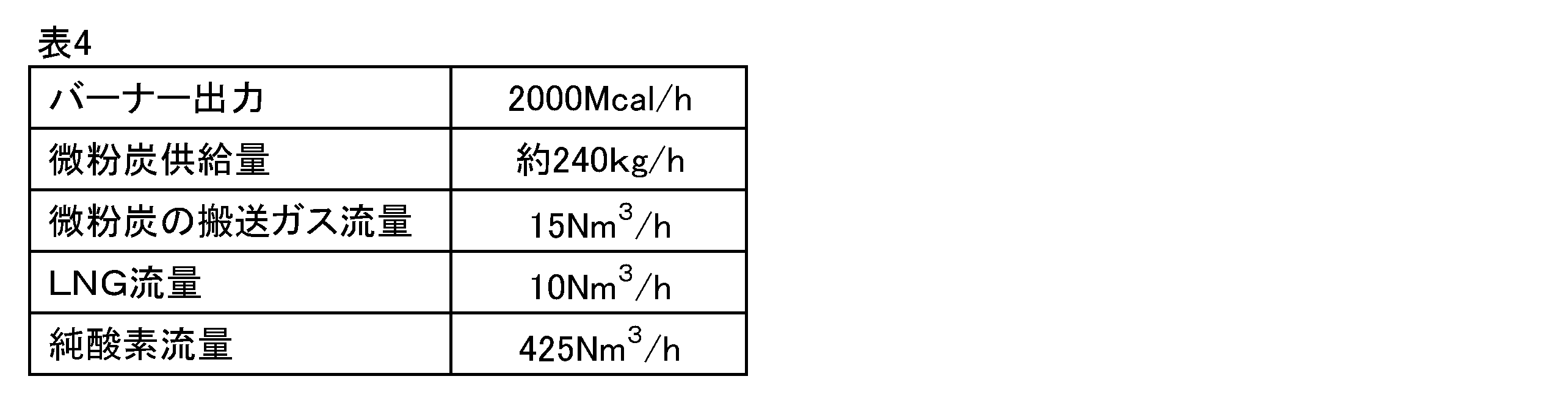
- Table 4 shows the output and usage conditions of this auxiliary burner.
- the component shown in Table 2 the lower heating value, and the particle size MDT were used.
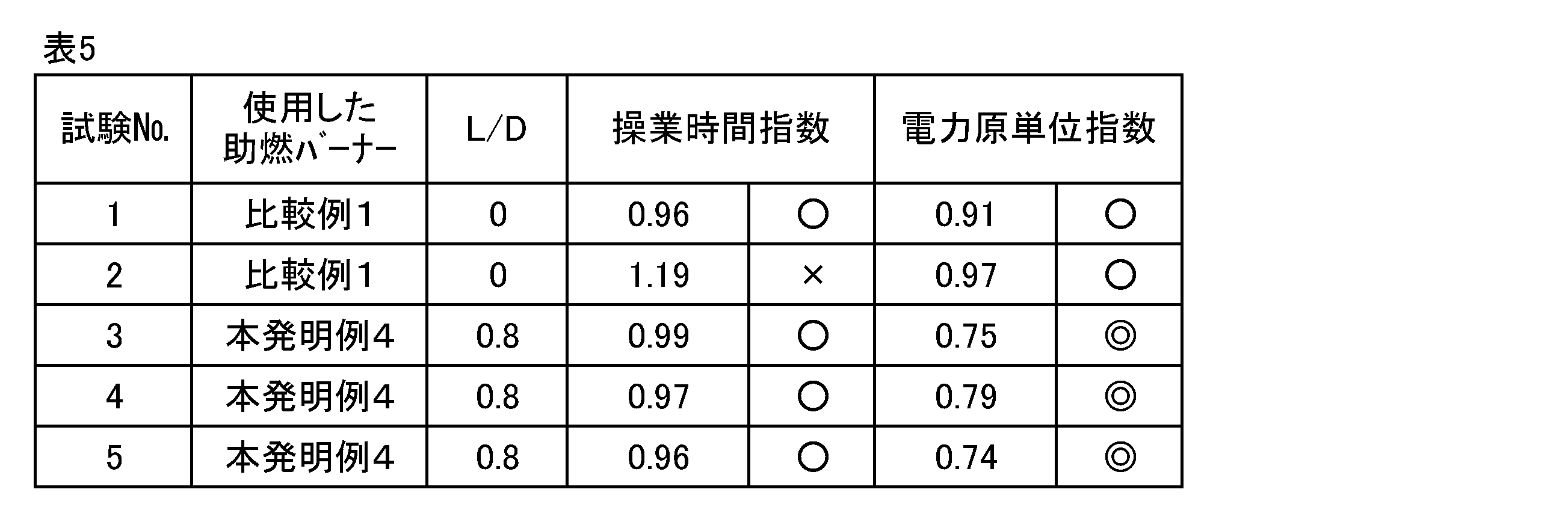
- the evaluation of the test was performed using the operating time index and the power consumption index.
- the operation time index is an index obtained by dividing the operation time in each test by the average operation time in normal operation.
- the power intensity index is an index obtained by dividing the power intensity in each test by the power intensity in normal operation. If each index is lower than 1.0, it indicates that there is a merit in the operation cost.
- the normal operation refers to an operation using an auxiliary combustion burner using only LNG as a fuel.
- the power consumption index was 0.75, 0.79, and 0.74, respectively, which was significantly lower than Test No. 1. This is considered to be due to the fact that the combustion rate of pulverized coal was improved and heat was applied to the scrap efficiently. Moreover, since there was no delay in operation time, it is considered that stable combustion was performed.
- the auxiliary combustion burner of the present invention can be said to be an auxiliary combustion burner that can realize stable combustion of solid fuel and reduce the operation cost. For this reason, by using the auxiliary combustion burner of the present invention, the cost of melting scrap in the electric furnace can be greatly reduced.
- the solid fuel can be efficiently burned together with the gaseous fuel at a high combustion rate, thereby obtaining a high heating effect of the iron-based scrap.
Landscapes
- Engineering & Computer Science (AREA)
- Mechanical Engineering (AREA)
- General Engineering & Computer Science (AREA)
- Chemical & Material Sciences (AREA)
- Combustion & Propulsion (AREA)
- Combustion Of Fluid Fuel (AREA)
Abstract
Description
[1]鉄系スクラップを溶解して溶鉄を製造する電気炉に付設され、燃料として気体燃料と固体燃料を用いる電気炉用助燃バーナーであって、
前記固体燃料が通過する第1流路を区画し、該第1流路の先端から前記固体燃料を噴射する固体燃料噴射管と、
前記固体燃料噴射管の周囲に配置され、前記固体燃料噴射管の外壁との間で前記気体燃料が通過する第2流路を区画し、該第2流路の先端から前記気体燃料を噴射する気体燃料噴射管と、
前記気体燃料噴射管の周囲に配置され、前記気体燃料噴射管の外壁との間で支燃性ガスが通過する第3流路を区画し、該第3流路の先端から前記支燃性ガスを噴射する支燃性ガス噴射管と、
を有し、
前記固体燃料噴射管の先端が前記気体燃料噴射管の内部に位置することにより、前記固体燃料噴射管の先端と前記気体燃料噴射管の先端との間に、前記気体燃料噴射管の先端側部分で囲まれた固体燃料・気体燃料予混合用の第1空間部が形成されたことを特徴とする電気炉用助燃バーナー。
・Lが短すぎる場合:固体燃料と気体燃料を予混合する時間と領域を確保しにくいため、予混合の効果が十分に得られない。
・Lが適切な場合:固体燃料と気体燃料が予混合され、固体燃料の燃焼性が改善する。
・Lが長すぎる場合:火炎がバーナー先端部に近づきすぎるため、バーナー先端部が溶損しやすくなる。
支燃性ガスの流量は、供給ガス量の中で最も多いことから、他の供給ガス(気体燃料及び搬送気体)と流速を合せるためには、支燃性ガス吐出口31の吐出面積を気体燃料吐出口21や固体燃料吐出口11よりも大きくする必要がある。その観点から、支燃性ガス噴射管3は最外周とするのが最適である。以下、支燃性ガスとして酸素を、気体燃料としてLNGを、固体燃料として微粉炭をそれぞれ使用する場合を例に説明する。
まず、燃焼に必要な酸素の量は下記(1)式により算出される。
燃焼に必要な酸素量=酸素比(係数)×[LNG流量×LNGの理論酸素量+微粉炭供給量×微粉炭の理論酸素量] …(1)
図1及び図2に示す構造の本発明例の助燃バーナーと、第1空間部4を有しない点を除いて同様の基本構造を有する比較例の助燃バーナーを用いて燃焼実験を行った。本発明例については、固体燃料噴射管の吐出口径Dは変更せず、第1空間部4のバーナー軸方向での長さLを種々変更して、表3に示す種々のL/Dで燃焼実験を行った。また、本発明例及び比較例ともに、第2空間部5は、L’/D’=0.8を満たす寸法とした。

ash0:微粉炭中の灰分の割合

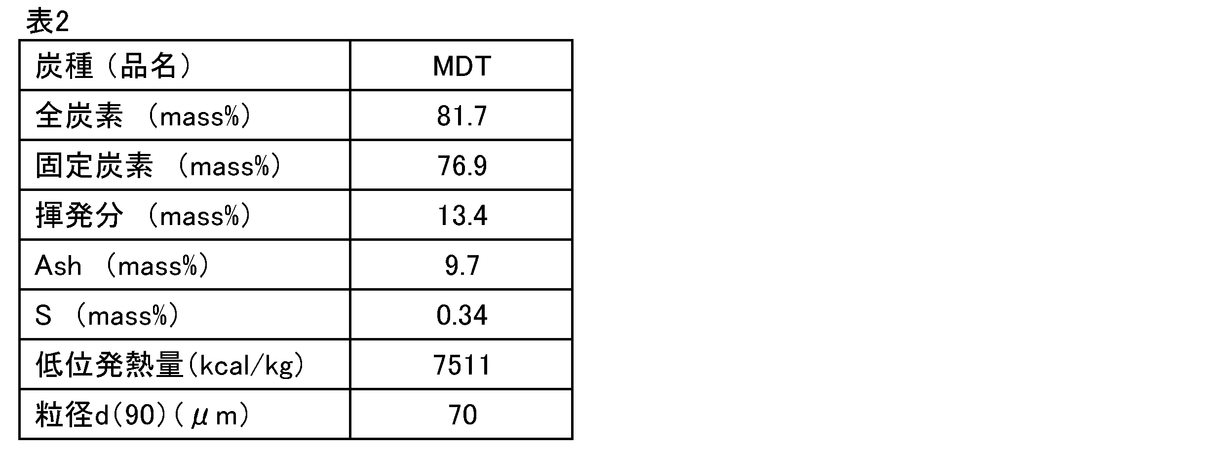
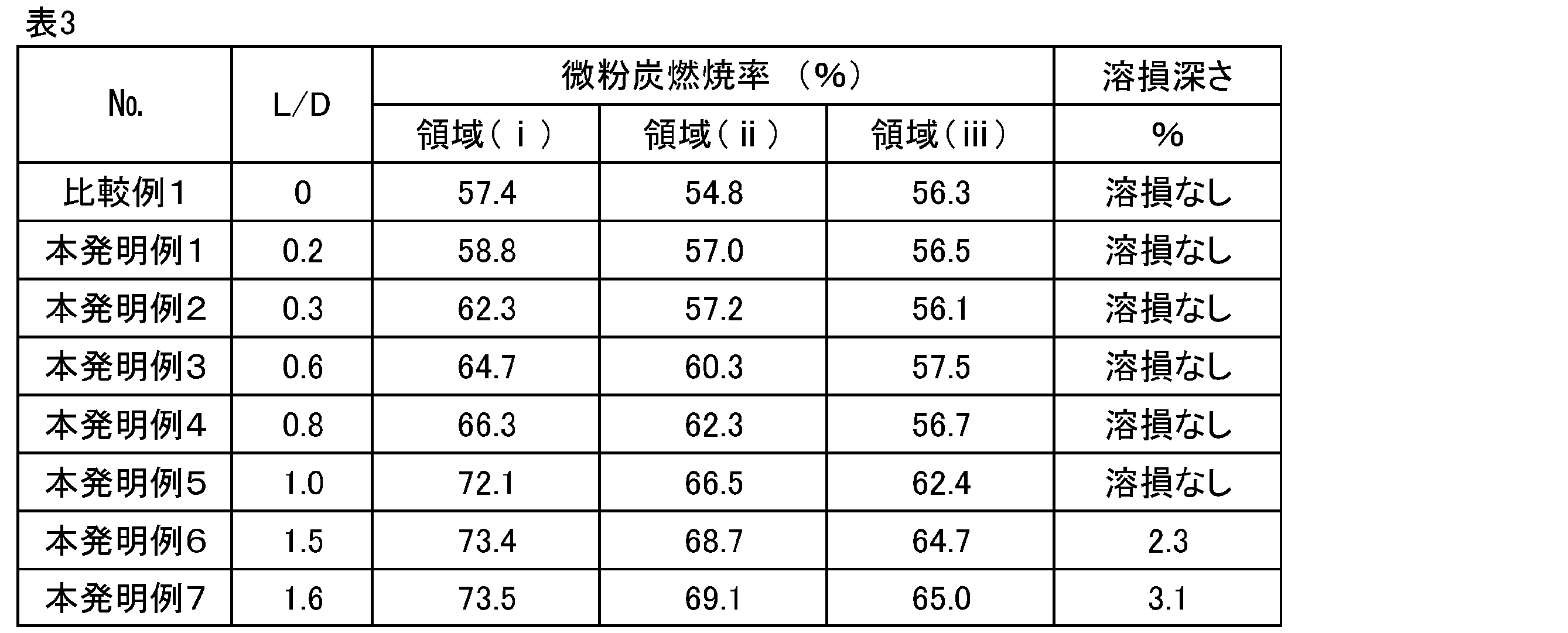
表3(実施例1)の本発明例4と比較例1の助燃バーナーをそれぞれ設置した電気炉で実証試験を行った。電気炉は、炉径が約6.3m、炉高が約4.1m、Tap容量が約120トンであり、中心に電極が1本ある直流タイプである。助燃バーナーは、炉体周方向の4箇所に設置される。
1 固体燃料噴射管
2 気体燃料噴射管
3 支燃性ガス噴射管
4 第1空間部
5 第2空間部
7 炉体
8 電極
x 鉄系スクラップ
10 固体燃料流路(第1流路)
11 固体燃料吐出口
12 固体燃料供給口
20 気体燃料流路(第2流路)
21 気体燃料吐出口
22 気体燃料供給口
30 支燃性ガス流路(第3流路)
31 支燃性ガス吐出口
32 支燃性ガス供給口
1A 固体燃料噴射管の先端
2A 気体燃料噴射管の先端
3A 支燃性ガス噴射管の先端
L 第1空間部のバーナー軸方向での長さ
D 固体燃料噴射管の吐出口径
Claims (5)
- 鉄系スクラップを溶解して溶鉄を製造する電気炉に付設され、燃料として気体燃料と固体燃料を用いる電気炉用助燃バーナーであって、
前記固体燃料が通過する第1流路を区画し、該第1流路の先端から前記固体燃料を噴射する固体燃料噴射管と、
前記固体燃料噴射管の周囲に配置され、前記固体燃料噴射管の外壁との間で前記気体燃料が通過する第2流路を区画し、該第2流路の先端から前記気体燃料を噴射する気体燃料噴射管と、
前記気体燃料噴射管の周囲に配置され、前記気体燃料噴射管の外壁との間で支燃性ガスが通過する第3流路を区画し、該第3流路の先端から前記支燃性ガスを噴射する支燃性ガス噴射管と、
を有し、
前記固体燃料噴射管の先端が前記気体燃料噴射管の内部に位置することにより、前記固体燃料噴射管の先端と前記気体燃料噴射管の先端との間に、前記気体燃料噴射管の先端側部分で囲まれた固体燃料・気体燃料予混合用の第1空間部が形成されたことを特徴とする電気炉用助燃バーナー。 - 前記第1空間部のバーナー軸方向での長さLと前記固体燃料噴射管の吐出口径Dが、0.2≦L/D≦1.5を満足する、請求項1に記載の電気炉用助燃バーナー。
- 前記気体燃料噴射管の先端が前記支燃性ガス噴射管の内部に位置することにより、前記気体燃料噴射管の先端と前記支燃性ガス噴射管の先端との間に、前記支燃性ガス噴射管の先端側部分で囲まれた保炎用の第2空間部が形成された、請求項1又は2に記載の電気炉用助燃バーナー。
- 請求項1~3のいずれか一項に記載の電気炉用助燃バーナーを備えることを特徴とする電気炉。
- 請求項1~3のいずれか一項に記載の電気炉用助燃バーナーを備えた電気炉において鉄系スクラップを溶解し、溶鉄を得ることを特徴とする溶鉄の製造方法。
Priority Applications (4)
| Application Number | Priority Date | Filing Date | Title |
|---|---|---|---|
| JP2017564755A JP6705838B2 (ja) | 2016-10-21 | 2017-09-27 | 電気炉用助燃バーナー |
| US16/342,413 US11293694B2 (en) | 2016-10-21 | 2017-09-27 | Auxiliary burner for electric furnace |
| KR1020197013956A KR102241090B1 (ko) | 2016-10-21 | 2017-09-27 | 전기로용 조연 버너 |
| CN201780065078.3A CN109844408B (zh) | 2016-10-21 | 2017-09-27 | 电炉用助燃燃烧器 |
Applications Claiming Priority (2)
| Application Number | Priority Date | Filing Date | Title |
|---|---|---|---|
| JP2016207050 | 2016-10-21 | ||
| JP2016-207050 | 2016-10-21 |
Publications (1)
| Publication Number | Publication Date |
|---|---|
| WO2018074166A1 true WO2018074166A1 (ja) | 2018-04-26 |
Family
ID=62018566
Family Applications (1)
| Application Number | Title | Priority Date | Filing Date |
|---|---|---|---|
| PCT/JP2017/035062 Ceased WO2018074166A1 (ja) | 2016-10-21 | 2017-09-27 | 電気炉用助燃バーナー |
Country Status (5)
| Country | Link |
|---|---|
| US (1) | US11293694B2 (ja) |
| JP (1) | JP6705838B2 (ja) |
| KR (1) | KR102241090B1 (ja) |
| CN (1) | CN109844408B (ja) |
| WO (1) | WO2018074166A1 (ja) |
Cited By (3)
| Publication number | Priority date | Publication date | Assignee | Title |
|---|---|---|---|---|
| JP2021001700A (ja) * | 2019-06-20 | 2021-01-07 | 三菱パワー株式会社 | ノズル及びノズルを備えたボイラ |
| WO2022172768A1 (ja) * | 2021-02-10 | 2022-08-18 | Jfeスチール株式会社 | 撮像装置付きバーナー、該バーナーを備える電気炉、及び、該電気炉を用いた溶鉄の製造方法 |
| EP4303327A4 (en) * | 2021-05-07 | 2024-10-30 | JFE Steel Corporation | ELECTRIC FURNACE AND STEELMAKING PROCESS |
Families Citing this family (4)
| Publication number | Priority date | Publication date | Assignee | Title |
|---|---|---|---|---|
| US11555612B2 (en) * | 2017-11-29 | 2023-01-17 | Babcock Power Services, Inc. | Dual fuel direct ignition burners |
| KR102477279B1 (ko) | 2019-06-14 | 2022-12-12 | 주식회사 엘지에너지솔루션 | 세퍼레이터 및 이를 포함하는 전기화학소자 |
| JP2023039683A (ja) * | 2021-09-09 | 2023-03-22 | 中外炉工業株式会社 | アンモニア燃料燃焼装置 |
| JP7828171B2 (ja) * | 2021-12-27 | 2026-03-11 | 川崎重工業株式会社 | バーナ及び燃焼炉 |
Citations (6)
| Publication number | Priority date | Publication date | Assignee | Title |
|---|---|---|---|---|
| GB2165633A (en) * | 1984-10-11 | 1986-04-16 | Air Prod & Chem | Pulverent fuel burner |
| JPH109524A (ja) * | 1996-06-20 | 1998-01-16 | Sumitomo Metal Ind Ltd | 電気炉用高速純酸素助燃バーナ |
| JP2003004382A (ja) * | 2001-06-20 | 2003-01-08 | Nikko:Kk | 電気炉用付帯設備及び電気炉 |
| JP2008209081A (ja) * | 2007-02-28 | 2008-09-11 | Jfe Steel Kk | バーナーの燃焼方法 |
| JP2012189311A (ja) * | 2011-02-21 | 2012-10-04 | Osaka Gas Co Ltd | 燃焼装置とその運転方法 |
| WO2016120943A1 (ja) * | 2015-01-27 | 2016-08-04 | Jfeスチール株式会社 | 電気炉による溶鉄の製造方法 |
Family Cites Families (4)
| Publication number | Priority date | Publication date | Assignee | Title |
|---|---|---|---|---|
| DE3690574C2 (de) * | 1985-11-15 | 1995-09-28 | Nippon Oxygen Co Ltd | Vorrichtung zum Erhitzen von Sauerstoff |
| FR2705363B1 (fr) | 1993-05-13 | 1995-08-11 | Clecim Sa | Procédé de fusion de ferraille dans un four électrique et installation pour la mise en Óoeuvre du procédé. |
| US5714113A (en) * | 1994-08-29 | 1998-02-03 | American Combustion, Inc. | Apparatus for electric steelmaking |
| US6752620B2 (en) * | 2002-01-31 | 2004-06-22 | Air Products And Chemicals, Inc. | Large scale vortex devices for improved burner operation |
-
2017
- 2017-09-27 WO PCT/JP2017/035062 patent/WO2018074166A1/ja not_active Ceased
- 2017-09-27 KR KR1020197013956A patent/KR102241090B1/ko active Active
- 2017-09-27 US US16/342,413 patent/US11293694B2/en active Active
- 2017-09-27 CN CN201780065078.3A patent/CN109844408B/zh active Active
- 2017-09-27 JP JP2017564755A patent/JP6705838B2/ja active Active
Patent Citations (6)
| Publication number | Priority date | Publication date | Assignee | Title |
|---|---|---|---|---|
| GB2165633A (en) * | 1984-10-11 | 1986-04-16 | Air Prod & Chem | Pulverent fuel burner |
| JPH109524A (ja) * | 1996-06-20 | 1998-01-16 | Sumitomo Metal Ind Ltd | 電気炉用高速純酸素助燃バーナ |
| JP2003004382A (ja) * | 2001-06-20 | 2003-01-08 | Nikko:Kk | 電気炉用付帯設備及び電気炉 |
| JP2008209081A (ja) * | 2007-02-28 | 2008-09-11 | Jfe Steel Kk | バーナーの燃焼方法 |
| JP2012189311A (ja) * | 2011-02-21 | 2012-10-04 | Osaka Gas Co Ltd | 燃焼装置とその運転方法 |
| WO2016120943A1 (ja) * | 2015-01-27 | 2016-08-04 | Jfeスチール株式会社 | 電気炉による溶鉄の製造方法 |
Cited By (5)
| Publication number | Priority date | Publication date | Assignee | Title |
|---|---|---|---|---|
| JP2021001700A (ja) * | 2019-06-20 | 2021-01-07 | 三菱パワー株式会社 | ノズル及びノズルを備えたボイラ |
| WO2022172768A1 (ja) * | 2021-02-10 | 2022-08-18 | Jfeスチール株式会社 | 撮像装置付きバーナー、該バーナーを備える電気炉、及び、該電気炉を用いた溶鉄の製造方法 |
| JPWO2022172768A1 (ja) * | 2021-02-10 | 2022-08-18 | ||
| JP7347675B2 (ja) | 2021-02-10 | 2023-09-20 | Jfeスチール株式会社 | 撮像装置付きバーナー、該バーナーを備える電気炉、及び、該電気炉を用いた溶鉄の製造方法 |
| EP4303327A4 (en) * | 2021-05-07 | 2024-10-30 | JFE Steel Corporation | ELECTRIC FURNACE AND STEELMAKING PROCESS |
Also Published As
| Publication number | Publication date |
|---|---|
| US11293694B2 (en) | 2022-04-05 |
| US20190249922A1 (en) | 2019-08-15 |
| JP6705838B2 (ja) | 2020-06-03 |
| CN109844408A (zh) | 2019-06-04 |
| JPWO2018074166A1 (ja) | 2018-10-18 |
| KR20190070943A (ko) | 2019-06-21 |
| KR102241090B1 (ko) | 2021-04-16 |
| CN109844408B (zh) | 2020-04-14 |
Similar Documents
| Publication | Publication Date | Title |
|---|---|---|
| JP6705838B2 (ja) | 電気炉用助燃バーナー | |
| JP6580710B2 (ja) | 電気炉用助燃バーナー | |
| JP5988014B1 (ja) | 電気炉による溶鉄の製造方法 | |
| JP6580709B2 (ja) | 電気炉用助燃バーナー | |
| WO2018179588A1 (ja) | バーナ及びバーナの運転方法、並びに冷鉄源の溶解・精錬方法 | |
| CN103649339B (zh) | 高炉操作方法 | |
| JP5216076B2 (ja) | スラグ溶融酸素バーナーを用いた溶融炉 | |
| JP6504370B2 (ja) | 電気炉による溶鉄の製造方法 | |
| KR102639551B1 (ko) | 전기로에 의한 용철의 제조 방법 | |
| WO2016139913A1 (ja) | 高炉操業方法 | |
| JP2018162919A (ja) | 助燃バーナーを備えた電気炉の操業方法 | |
| KR100867054B1 (ko) | 고로에의 환원재 취입장치, 그 장치를 사용한 고로조업방법 | |
| JP4016909B2 (ja) | 粉体燃焼装置および粉体燃焼方法 | |
| CN101684939B (zh) | 工业炉中固体燃料燃烧的方法和系统 | |
| JPS6287709A (ja) | 低カロリ−ガスを助燃燃料とする粉炭バ−ナ | |
| JP2006241585A (ja) | 高炉への還元材吹込み装置、該装置を用いた高炉操業方法 |
Legal Events
| Date | Code | Title | Description |
|---|---|---|---|
| WWE | Wipo information: entry into national phase |
Ref document number: 2017564755 Country of ref document: JP |
|
| 121 | Ep: the epo has been informed by wipo that ep was designated in this application |
Ref document number: 17861452 Country of ref document: EP Kind code of ref document: A1 |
|
| NENP | Non-entry into the national phase |
Ref country code: DE |
|
| ENP | Entry into the national phase |
Ref document number: 20197013956 Country of ref document: KR Kind code of ref document: A |
|
| 122 | Ep: pct application non-entry in european phase |
Ref document number: 17861452 Country of ref document: EP Kind code of ref document: A1 |