WO2018074019A1 - 光学フィルムの製造方法 - Google Patents
光学フィルムの製造方法 Download PDFInfo
- Publication number
- WO2018074019A1 WO2018074019A1 PCT/JP2017/026086 JP2017026086W WO2018074019A1 WO 2018074019 A1 WO2018074019 A1 WO 2018074019A1 JP 2017026086 W JP2017026086 W JP 2017026086W WO 2018074019 A1 WO2018074019 A1 WO 2018074019A1
- Authority
- WO
- WIPO (PCT)
- Prior art keywords
- casting
- dope
- film
- bis
- resin
- Prior art date
- Legal status (The legal status is an assumption and is not a legal conclusion. Google has not performed a legal analysis and makes no representation as to the accuracy of the status listed.)
- Ceased
Links
Images


Classifications
-
- B—PERFORMING OPERATIONS; TRANSPORTING
- B29—WORKING OF PLASTICS; WORKING OF SUBSTANCES IN A PLASTIC STATE IN GENERAL
- B29C—SHAPING OR JOINING OF PLASTICS; SHAPING OF MATERIAL IN A PLASTIC STATE, NOT OTHERWISE PROVIDED FOR; AFTER-TREATMENT OF THE SHAPED PRODUCTS, e.g. REPAIRING
- B29C41/00—Shaping by coating a mould, core or other substrate, i.e. by depositing material and stripping-off the shaped article; Apparatus therefor
- B29C41/24—Shaping by coating a mould, core or other substrate, i.e. by depositing material and stripping-off the shaped article; Apparatus therefor for making articles of indefinite length
-
- B—PERFORMING OPERATIONS; TRANSPORTING
- B29—WORKING OF PLASTICS; WORKING OF SUBSTANCES IN A PLASTIC STATE IN GENERAL
- B29C—SHAPING OR JOINING OF PLASTICS; SHAPING OF MATERIAL IN A PLASTIC STATE, NOT OTHERWISE PROVIDED FOR; AFTER-TREATMENT OF THE SHAPED PRODUCTS, e.g. REPAIRING
- B29C41/00—Shaping by coating a mould, core or other substrate, i.e. by depositing material and stripping-off the shaped article; Apparatus therefor
- B29C41/34—Component parts, details or accessories; Auxiliary operations
- B29C41/52—Measuring, controlling or regulating
-
- B—PERFORMING OPERATIONS; TRANSPORTING
- B29—WORKING OF PLASTICS; WORKING OF SUBSTANCES IN A PLASTIC STATE IN GENERAL
- B29D—PRODUCING PARTICULAR ARTICLES FROM PLASTICS OR FROM SUBSTANCES IN A PLASTIC STATE
- B29D11/00—Producing optical elements, e.g. lenses or prisms
- B29D11/00634—Production of filters
- B29D11/00644—Production of filters polarizing
-
- B—PERFORMING OPERATIONS; TRANSPORTING
- B29—WORKING OF PLASTICS; WORKING OF SUBSTANCES IN A PLASTIC STATE IN GENERAL
- B29D—PRODUCING PARTICULAR ARTICLES FROM PLASTICS OR FROM SUBSTANCES IN A PLASTIC STATE
- B29D11/00—Producing optical elements, e.g. lenses or prisms
- B29D11/0074—Production of other optical elements not provided for in B29D11/00009- B29D11/0073
- B29D11/00788—Producing optical films
-
- G—PHYSICS
- G02—OPTICS
- G02B—OPTICAL ELEMENTS, SYSTEMS OR APPARATUS
- G02B5/00—Optical elements other than lenses
- G02B5/30—Polarising elements
-
- B—PERFORMING OPERATIONS; TRANSPORTING
- B29—WORKING OF PLASTICS; WORKING OF SUBSTANCES IN A PLASTIC STATE IN GENERAL
- B29K—INDEXING SCHEME ASSOCIATED WITH SUBCLASSES B29B, B29C OR B29D, RELATING TO MOULDING MATERIALS OR TO MATERIALS FOR MOULDS, REINFORCEMENTS, FILLERS OR PREFORMED PARTS, e.g. INSERTS
- B29K2023/00—Use of polyalkenes or derivatives thereof as moulding material
-
- B—PERFORMING OPERATIONS; TRANSPORTING
- B29—WORKING OF PLASTICS; WORKING OF SUBSTANCES IN A PLASTIC STATE IN GENERAL
- B29K—INDEXING SCHEME ASSOCIATED WITH SUBCLASSES B29B, B29C OR B29D, RELATING TO MOULDING MATERIALS OR TO MATERIALS FOR MOULDS, REINFORCEMENTS, FILLERS OR PREFORMED PARTS, e.g. INSERTS
- B29K2033/00—Use of polymers of unsaturated acids or derivatives thereof as moulding material
- B29K2033/04—Polymers of esters
- B29K2033/08—Polymers of acrylic acid esters, e.g. PMA, i.e. polymethylacrylate
-
- B—PERFORMING OPERATIONS; TRANSPORTING
- B29—WORKING OF PLASTICS; WORKING OF SUBSTANCES IN A PLASTIC STATE IN GENERAL
- B29K—INDEXING SCHEME ASSOCIATED WITH SUBCLASSES B29B, B29C OR B29D, RELATING TO MOULDING MATERIALS OR TO MATERIALS FOR MOULDS, REINFORCEMENTS, FILLERS OR PREFORMED PARTS, e.g. INSERTS
- B29K2079/00—Use of polymers having nitrogen, with or without oxygen or carbon only, in the main chain, not provided for in groups B29K2061/00 - B29K2077/00, as moulding material
- B29K2079/08—PI, i.e. polyimides or derivatives thereof
Definitions
- the present invention relates to a method for producing an optical film containing any one of a polyimide resin, a cycloolefin resin, and a polyarylate resin.
- Patent Document 1 As a method for producing an excellent optical film using a cellulose acylate resin, for example, there are methods disclosed in Patent Documents 1 to 3.
- the speed at which the dope of the optical film is discharged from the casting die is V1 (m / min) and the moving speed of the support is V2 (m / min)
- the speed difference V2 ⁇ V1
- Patent Document 3 due to the difference in the discharge speed of the dope discharged from the discharge port depending on the position in the longitudinal direction of the discharge port of the casting die, the entrainment of bubbles at the end of the resin film Based on the assumption that a failure due to vibration of the support (horizontal unevenness) occurs, the dope discharge rate at both ends of the casting die discharge port, and the dope discharge rate at the center of the casting die discharge port, The ratio is made close to 1.
- JP 2001-71338 A (refer to claim 1, paragraph [0009], etc.)
- International Publication No. WO2012-056619 see claim 1, paragraphs [0025] to [0040] etc.
- a cellulose acylate resin for example, a cellulose triacetate resin
- a polarizer for example, a polarizer during the production of a polarizing plate
- resins other than cellulose ester resins are now being adopted.
- a polyimide resin, a cycloolefin resin, and a polyarylate resin there is an increasing need for a thin film using a polyimide resin, a cycloolefin resin, and a polyarylate resin.
- Patent Documents 1 to 3 when manufacturing a thin film using a polyimide resin, a cycloolefin resin, or a polyarylate resin, the methods of Patent Documents 1 to 3 were applied. It was found that phase difference unevenness occurred and horizontal step unevenness occurred in the cast film. About the reason, this inventor estimates as follows.
- the casting film is dried on the support and peeled off from the support, but the casting film shrinks during drying on the support.
- the adhesion force between the support and the casting film is larger than the contraction force of the casting film, the casting film is hardly peeled off from the support.
- the peeling of the casting film is stable, and the peeling position in the width direction of the casting film varies in the transport direction of the casting film, so-called peeling unevenness. It rarely happens.
- the peeling tension is not evenly applied in the width direction of the casting film 101. Therefore, the orientation direction of the molecules at the center portion 101a and the end portion 101b of the casting film 101. It varies. As a result, phase difference unevenness occurs in the width direction of the casting film 101.
- the discharge of dope containing polyimide resin, cycloolefin resin, and polyarylate resin is less stable than the discharge of dope containing cellulose acylate resin due to the difference in resin type, and disturbance (for example, vibration of the support) during discharge is difficult. It becomes easy to shake under the influence. As a result, as shown in FIG. 10, horizontal unevenness (film thickness unevenness in the casting direction) is likely to occur in the casting film 101 on the support 100.
- the present invention has been made to solve the above-described problems, and its purpose is to cast an optical film using any one of a polyimide resin, a cycloolefin resin, and a polyarylate resin.
- a method for producing an optical film capable of reducing peeling unevenness by stabilizing peeling from a support of a film, thereby reducing retardation unevenness in the width direction and reducing horizontal unevenness. is there.
- the method for producing an optical film according to one aspect of the present invention is a method for producing an optical film by a solution casting method,
- a dope containing any one of a polyimide resin, a cycloolefin resin, and a polyarylate resin and a solvent is discharged from a casting die, cast on a moving support, and the cast dope is dried to flow.
- the dope discharge speed from the casting width end portion of the casting die is V 1E (m / min)
- the dope discharging speed from the casting width center portion of the casting die is V 1C (m / min).
- the moving speed of the support is V 2 (m / min)
- the following conditional expressions (1) and (2) are simultaneously satisfied: (1) V 2 > V 1C (2) (V 2 / V 1E)> (V 2 / V 1C) It is.
- the peeling unevenness from the support of the casting film is reduced and the width direction is reduced. Phase difference unevenness can be reduced, and horizontal step unevenness can be reduced.
- the numerical value range includes the values of the lower limit A and the upper limit B.
- the method for producing an optical film of the present embodiment is a method for producing an optical film by a solution casting film forming method, and includes a dope containing any one of a polyimide resin, a cycloolefin resin, and a polyarylate resin, and a solvent.
- a casting process in which a casting film is discharged from a casting die, cast on a moving support, the cast dope is dried to form a casting film, and a peeling process in which the casting film is peeled off from the support.
- the dope discharge speed from the casting width end portion of the casting die is V 1E (m / min)
- the dope discharging speed from the casting width center portion of the casting die is V 1C (m / min).
- the moving speed of the support is V 2 (m / min)
- the following conditional expressions (1) and (2) are satisfied simultaneously. That is, (1) V 2 > V 1C (2) (V 2 / V 1E)> (V 2 / V 1C) It is.
- the casting width end portion of the casting die means the end portion in the width direction including the edge of the casting film on the support (the width is the total width of the casting film). 10% or less) is a region where a dope is discharged.
- the casting width center part of a casting die refers to the area
- the width in the casting direction of the central portion of the casting width is not particularly limited, but here, for example, a width of 10% or less of the entire width of the casting film is considered.
- conditional expression (1) the dope discharged from the center of the casting width of the casting die is pulled (stretched) in the casting direction (moving direction of the support) by the movement of the support.
- conditional expression (2) the dope discharged from the casting width end portion of the casting die is pulled further in the casting direction than the dope discharged from the casting width center portion.
- the end portion of the casting film is less likely to be peeled off from the support prior to the central portion, and variations in the peeling position in the width direction of the casting film, that is, peeling unevenness can be reduced.
- the peeling tension is evenly applied in the width direction of the casting film, so that the orientation direction of molecules at the end and the center of the casting film is reduced. It is possible to reduce the occurrence of unevenness in the retardation in the width direction of the cast film.
- conditional expression (2) is satisfied, that is, the dope discharged from the casting width end portion of the casting die is pulled further in the casting direction than the dope discharged from the casting width central portion.
- the dope discharged from the end portion of the casting width is stable and hardly shaken. Accordingly, even when a dope containing any one of a polyimide resin, a cycloolefin resin, and a polyarylate resin is cast on a support, the entire dope is shaken due to the influence of disturbance (for example, vibration of the support). Therefore, it is possible to reduce film thickness unevenness that occurs in the casting direction, that is, horizontal step unevenness.
- the manufacturing method of the present embodiment satisfies the conditional expressions (1) and (2), so that the dope discharged from the casting die is pulled in the casting direction (discharge direction) in the full width. Even if the film is formed using resin other than cellulose ester resin, such as polyimide resin, cycloolefin resin, polyarylate resin, etc. by positively changing the discharge rate of dope in the width direction. And phase difference unevenness can be reduced. From this, the manufacturing method of this embodiment that positively changes the dope discharge speed in the width direction is a film formation using a cellulose ester resin, and the dope discharge speed is made uniform in the width direction. It can be said that the technical idea is completely different from the manufacturing method No. 3.
- the manufacturing method of the present embodiment further satisfies the following conditional expression (3). That is, (3) 3 ⁇ (V 2 / V 1C ) ⁇ 10 It is.
- V 2 / V 1C When the value of V 2 / V 1C is lower than the lower limit, the effect of extending the dope discharged from the casting width central portion of the casting die in the casting direction by the movement of the support becomes small. It becomes difficult to increase the strength of the central portion. For this reason, at the time of peeling from the support, the center portion of the casting film easily flutters, causing peeling unevenness, and it becomes difficult to obtain the effect of reducing retardation unevenness.
- the value of V 2 / V 1C exceeds the upper limit, the moving speed of the support becomes too fast with respect to the dope discharge speed, and the support becomes easy to vibrate. As a result, the dope discharged from the substrate tends to sway, and horizontal unevenness tends to occur.
- the manufacturing method of the present embodiment further satisfies the following conditional expression (4). That is, (4) 1.05 ⁇ (V 2 / V 1E ) / (V 2 / V 1C ) ⁇ 1.5 It is.
- the more desirable range of V 2 / V 1C is represented by the following conditional expression (3 ′), and the more desirable range of (V 2 / V 1E ) / (V 2 / V 1C ) is the following conditional expression (4 ') That is, it is desirable that the manufacturing method of the present embodiment further satisfies the following conditional expressions (3 ′) and (4 ′) from the viewpoint of surely reducing both the phase difference unevenness and the horizontal step unevenness. That is, (3 ′) 4.6 ⁇ (V 2 / V 1C ) ⁇ 5.0 (4 ′) 1.2 ⁇ (V 2 / V 1E ) / (V 2 / V 1C ) ⁇ 1.3 It is.
- the dope discharge speed V 1E may be made slower than the discharge speed V 1C by changing the gap of the slit from which the dope is discharged in the casting die in the casting width direction. That is, V 1E ⁇ V 1C may be realized by widening the slit gap of the casting die at the casting width end portion rather than the casting width central portion. Since V 1E ⁇ V 1C can be easily realized by controlling the slit gap, it is easy to satisfy the conditional expression (2), (4) or (4 ′) described above, and the effects of the present embodiment described above can be obtained. It is easy to obtain.
- FIG. 1 is an explanatory diagram illustrating a schematic configuration of an optical film manufacturing apparatus 1 according to the present embodiment.
- FIG. 2 is a flowchart which shows the flow of the manufacturing process of an optical film.
- the manufacturing method of the optical film of this embodiment is a method of manufacturing an optical film by a solution casting film forming method. As shown in FIG. 2, a stirring preparation step (S1), a casting step (S2), and a peeling step.
- ⁇ Stirring preparation step> At least the resin and the solvent are stirred in the stirring tank 51 of the stirring device 50 to prepare a dope that is cast on the support 3 (endless belt).
- a polyimide resin, a cycloolefin resin, and a polyarylate resin is used as the resin.
- the solvent a mixed solvent of a good solvent and a poor solvent is used.
- the dope prepared in the stirring preparation step is fed to the casting die 2 by a conduit through a pressurized metering gear pump or the like, and transferred onto the support 3 made of a rotationally driven stainless steel endless belt for infinite transfer.
- the dope is cast from the casting die 2 at the casting position.
- the cast dope is dried on the support 3 to form a cast film 5 (web).
- the inclination of the casting die 2, that is, the discharge direction of the dope from the casting die 2 to the support 3 is an angle of 0 ° to 90 ° with respect to the normal of the surface of the support 3 (the surface on which the dope is cast). It may be set as appropriate so that it falls within the range.
- the details of the casting die 2 will be described later.
- the support 3 is held by a pair of rolls 3a and 3b and a plurality of rolls (not shown) positioned therebetween.
- One or both of the rolls 3a and 3b are provided with a driving device (not shown) for applying tension to the support 3 so that the support 3 is used in a tensioned state.
- the casting film 5 formed by the dope cast on the support 3 is heated on the support 3, and the casting film 5 can be peeled from the support 3 by the peeling roll 4. Until the solvent is evaporated.
- the solvent there are a method of blowing air from the web side, a method of transferring heat from the back surface of the support 3 by a liquid, a method of transferring heat from the front and back by radiant heat, and the like. That's fine.
- the residual solvent amount of the cast film 5 on the support 3 at the time of peeling is desirably in the range of 50 to 120% by mass depending on the strength of drying conditions, the length of the support 3 and the like.
- the amount of residual solvent is determined.
- the residual solvent amount is defined by the following formula.
- Residual solvent amount (% by mass) (mass before web heat treatment ⁇ mass after web heat treatment) / (mass after web heat treatment) ⁇ 100
- the heat treatment for measuring the residual solvent amount represents performing heat treatment at 115 ° C. for 1 hour.
- the cast film 5 peeled from the support 3 is dried by a drying device 6.
- the drying device 6 the casting film 5 is transported by a plurality of transporting rolls arranged in a staggered manner as viewed from the side, and the casting film 5 is dried in the meantime.
- the drying method in the drying apparatus 6 Generally the casting film 5 is dried using a hot air, infrared rays, a heating roll, a microwave. From the viewpoint of simplicity, a method of drying the cast film 5 with hot air is preferable. In addition, what is necessary is just to perform a 1st drying process as needed.
- the stretching step the cast film 5 dried by the drying device 6 is stretched by the tenter 7.
- the stretching direction at this time is one of a film transport direction (MD direction; Machine Direction), a lateral direction (TD direction; Transverse Direction) perpendicular to the transport direction in the film plane, and both of these directions.
- MD direction film transport direction
- TD direction lateral direction
- Transverse Direction lateral direction perpendicular to the transport direction in the film plane
- both side edges of the cast film 5 are fixed with clips or the like and stretched is preferable in order to improve the flatness and dimensional stability of the film.
- the casting film 5 can be stretched (obliquely stretched) in a direction obliquely intersecting the MD direction and the TD direction by stretching the casting film 5 in both the MD direction and the TD direction. .
- ⁇ Second drying step> The cast film 5 stretched by the tenter 7 is dried by the drying device 8.
- the drying device 8 the casting film 5 is conveyed by a plurality of conveying rolls arranged in a staggered manner as viewed from the side, and the casting film 5 is dried in the meantime.
- the drying method in the drying apparatus 8 Generally, the casting film 5 is dried using a hot air, infrared rays, a heating roll, a microwave, etc. From the viewpoint of simplicity, a method of drying the cast film 5 with hot air is preferable.
- the cast film 5 is dried by the drying device 8 and then conveyed toward the winding device 11 as the optical film F.
- a cutting portion 9 and an embossing portion 10 are arranged in this order.
- disconnects the both ends of the width direction with a slitter is performed, conveying the optical film F formed into a film.
- the part remaining after the cutting of both ends constitutes a product part to be a film product.
- disconnected from the optical film F is collect
- embossing is performed by the embossing unit 10 on both ends of the optical film F in the width direction. Embossing is performed by pressing a heated embossing roller against both ends of the optical film F. Fine irregularities are formed on the surface of the embossing roller, and by pressing the embossing roller against both ends of the optical film F, the irregularities are formed at both ends.
- the optical film F that has been embossed is wound up by the winding device 11 to obtain the original roll (film roll) of the optical film F. That is, in the winding process, the film roll is manufactured by winding the optical film F around the core while transporting the optical film F.
- the winding method of the optical film F may be a commonly used winder, and there are methods for controlling tension such as a constant torque method, a constant tension method, a taper tension method, a program tension control method with a constant internal stress, and the like. You can use them properly.
- the winding length of the optical film F is preferably 1000 to 7200 m. Further, the width at that time is desirably 1000 to 3200 mm, and the film thickness is desirably 10 to 60 ⁇ m.
- the discharge speed of the dope from the casting width end of the casting die 2 is V 1E (m / min), and the discharging speed of the dope from the center of the casting width of the casting die 2 is V 1C (m / min).
- the moving speed of the support 3 is V 2 (m / min)
- the casting die is set so as to satisfy the conditional expressions (1) to (4) described above.
- the dope is discharged from 2 toward the support 3 and the support 3 is moved (running). Thereby, although the phase difference unevenness and the horizontal step unevenness can be reduced, the detailed reason is as described above.
- FIG. 3 schematically shows the relationship between the dope discharge speeds V 1E and V 1C and the moving speed V 2 of the support 3 in the casting process of the present embodiment.
- the length of the arrow in the figure corresponds to the magnitude of the speed.
- the dope discharge speeds V 1E and V 1C are slower than the moving speed of the support 3, and the dope discharge speed V 1E is further slower than the dope discharge speed V 1C .
- the draw ratio indicating the ratio between the moving speed of the support 3 and the dope discharge speed is different in the casting width direction. That is, in the present embodiment, (V 2 / V 1E )> (V 2 / V 1C ).
- V 2 / V 1E is also referred to as a draw ratio VA
- V 2 / V 1C is also referred to as a draw ratio VB.
- any of the following three methods can be adopted.
- FIG. 4 is a vertical sectional view showing an example of the configuration of the casting die 2.
- the dope prepared in the dope preparation kettle is supplied to the casting die 2 through, for example, a pump (not shown), and is accommodated in a depression inside the casting die 2, that is, in the manifold 2m.
- the above-described manifold 2m is originally designed so that the dope is uniformly spread from the casting width center portion 2a to the casting width end portion 2b inside the casting die 2.
- the shape of the manifold 2m is designed so that the dope concentrates on the casting width central portion 2a rather than the extending width end portion 2b.
- FIG. 5 is an explanatory diagram schematically showing another configuration example of the casting die 2.
- a casting die 2 flows two doped supply ports 2A 1 and dope supply ports 2A 2 corresponding to casting width central portion 2a and the casting width end 2b, and the dope supply ports 2A 1 ⁇ 2A 2
- Dope communication paths 2B 1 and 2B 2 for guiding the dope into the manifold 2m are provided.
- Doped supply ports 2A 1 is connected to the first pump P 1
- doped supply ports 2A 2 is coupled to the second pump P 2.
- first pump P 1 of the dope supply capacity is higher than the second doped supply capacity of the pump P 2, doped supply ports 2A 1 and doped with each other by the first pump P 1 supplying rate at which the dope is supplied into the manifold 2m through the passageway 2B 1 is supplied to the manifold 2m through the dope supply ports 2A 2 and doped communicating passage 2B 2 by the second pump P 2 More than the supply amount of dope per unit time. Therefore, by setting the dope supply capability of the first pump P 1 and the second pump P 2 as described above, V 1C > V 1E is realized as the relationship of the dope discharge speed from the casting die 2.
- the draw ratio VA and the draw ratio VB can be made different.
- the inner diameters of the dope communication passages 2B 1 and 2B 2 communicating with the dope supply ports 2A 1 and 2A 2 are set as the dope supply of the first pump P 1 and the second pump P 2 .
- the inner diameters of the dope communication passages 2B 1 and 2B 2 may be the same as long as the dope supply capacities of the first pump P 1 and the second pump P 2 are different. .
- FIG. 6 is a horizontal sectional view showing still another configuration of the casting die 2.
- the casting die 2 has a slit 31 serving as a dope outlet.
- the slit 31 is formed by a pair of lips.
- One lip is a flexible lip 32 that has low rigidity and is easily deformed, and the other lip is a fixed lip 33.
- the slit 31 includes a casting width central portion 2a for discharging the dope and a casting width end portion 2b.
- the casting die 2 is provided with a plurality of heat bolts 34 for adjusting the width of the slit 31 (the opening length in the dope casting direction, hereinafter also referred to as “slit gap”).
- the plurality of heat bolts 34 are arranged side by side at a substantially constant interval in the casting width direction of the casting die 2 (longitudinal direction of the slit 31).
- the casting die 2 is provided with a block (not shown) having an embedded electric heater and a cooling medium passage corresponding to each heat bolt 34, and each heat bolt 34 passes through each block.
- the slit gap can be adjusted by displacing the flexible lip 32 by increasing or decreasing the input of the embedded electric heater to raise or lower the temperature of the block and thermally expanding and contracting the heat bolt 34 while constantly cooling the block.
- FIG. 7 schematically shows the difference in the dope discharge speed due to the difference in the slit gap of the casting die 2.
- the slit gap is wide, the discharge speed V 1-1 of the dope becomes slow, the slit gap If it is narrow, the dope discharge speed V 1-2 becomes faster (V 1-2 > V 1-1 ). Therefore, as shown in FIG. 6, the slit gap is controlled by controlling each heat bolt 34 so that the slit gap of the casting die 2 becomes wider at the casting width end portion 2 b than at the casting width central portion 2 a.
- V 1C > V 1E can be easily realized as the dope discharge speed, whereby the draw ratio VA and the draw ratio VB can be made different.
- any of a polyimide resin, a cycloolefin resin, and a polyarylate resin can be used as the resin used for manufacturing the optical film, that is, the resin contained in the dope.
- polyimide (A) a polyimide having a repeating unit represented by the following general formula (I) (hereinafter referred to as polyimide (A)) can be used.
- the polyimide (A) can be obtained by imidizing polyamic acid having a repeating unit represented by the following general formula (I ′) (hereinafter referred to as polyamic acid (A ′)).
- R represents an aromatic hydrocarbon ring or an aromatic heterocyclic ring, or a tetravalent aliphatic hydrocarbon group or alicyclic hydrocarbon group having 4 to 39 carbon atoms.
- ⁇ is a group composed of a divalent aliphatic hydrocarbon group having 2 to 39 carbon atoms, an alicyclic hydrocarbon group, an aromatic hydrocarbon group, or a combination thereof, and —O—, At least selected from the group consisting of —SO 2 —, —CO—, —CH 2 —, —C (CH 3 ) 2 —, —OSi (CH 3 ) 2 —, —C 2 H 4 O— and —S—.
- One group may be contained.
- Examples of the aromatic hydrocarbon ring represented by R include a benzene ring, biphenyl ring, naphthalene ring, azulene ring, anthracene ring, phenanthrene ring, pyrene ring, chrysene ring, naphthacene ring, triphenylene ring, and o-terphenyl ring.
- Examples of the aromatic heterocycle represented by R include a silole ring, furan ring, thiophene ring, oxazole ring, pyrrole ring, pyridine ring, pyridazine ring, pyrimidine ring, pyrazine ring, triazine ring, and oxadiazole ring.
- Triazole ring imidazole ring, pyrazole ring, thiazole ring, indole ring, benzimidazole ring, benzthiazole ring, benzoxazole ring, quinoxaline ring, quinazoline ring, phthalazine ring, thienothiophene ring, carbazole ring, azacarbazole ring (carbazole ring) Any one or more of the carbon atoms constituting the dibenzosilole ring, dibenzofuran ring, dibenzothiophene ring, benzothiophene ring or dibenzofuran ring.
- Examples of the tetravalent aliphatic hydrocarbon group having 4 to 39 carbon atoms represented by R include a butane-1,1,4,4-triyl group, an octane-1,1,8,8-triyl group, Examples include decane-1,1,10,10-triyl group.
- Examples of the tetravalent alicyclic hydrocarbon group having 4 to 39 carbon atoms represented by R include cyclobutane-1,2,3,4-tetrayl group, cyclopentane-1,2,4,5. -Tetrayl group, cyclohexane-1,2,4,5-tetrayl group, bicyclo [2.2.2] oct-7-ene-2,3,5,6-tetrayl group, bicyclo [2.2.2] Octane-2,3,5,6-tetrayl group, 3,3 ′, 4,4′-dicyclohexyltetrayl group, 3,6-dimethylcyclohexane-1,2,4,5-tetrayl group, 3,6- And groups such as diphenylcyclohexane-1,2,4,5-tetrayl group.
- Examples of the divalent aliphatic hydrocarbon group having 2 to 39 carbon atoms with or without the bonding group represented by ⁇ include groups represented by the following structural formula.
- n represents the number of repeating units, preferably 1 to 5, and more preferably 1 to 3.
- X is an alkanediyl group having 1 to 3 carbon atoms, that is, a methylene group, an ethylene group, a trimethylene group, or a propane-1,2-diyl group, and a methylene group is preferable.
- Examples of the divalent alicyclic hydrocarbon group having 2 to 39 carbon atoms with or without the above-described bonding group represented by ⁇ include groups represented by the following structural formula.
- Examples of the divalent aromatic hydrocarbon group having 2 to 39 carbon atoms with or without the above-described bonding group represented by ⁇ include groups represented by the following structural formulas.
- Examples of the group composed of a combination of an aliphatic hydrocarbon group, an alicyclic hydrocarbon group and an aromatic hydrocarbon group represented by ⁇ include groups represented by the following structural formula.
- the group represented by ⁇ is preferably a divalent aromatic hydrocarbon group having 2 to 39 carbon atoms having a linking group, or a combination of the aromatic hydrocarbon group and an aliphatic hydrocarbon group.
- a group represented by the following structural formula is preferred.
- the repeating unit represented by the general formula (I) is preferably 10 to 100 mol%, more preferably 50 to 100 mol%, still more preferably 80 to 100 mol%, particularly preferably all the repeating units. 90 to 100 mol%.
- the number of repeating units of the general formula (I) in one molecule of polyimide (A) is 10 to 2000, preferably 20 to 200, and within this range, the glass transition temperature is 230 to 350 ° C. Is more preferable, and 250 to 330 ° C. is more preferable.
- Polyimide (A) is prepared by reacting an aromatic, aliphatic or alicyclic tetracarboxylic acid or a derivative thereof with a diamine or a derivative thereof to prepare a polyamic acid (A ′). Obtained by imidization.
- aliphatic or alicyclic tetracarboxylic acid derivatives examples include aliphatic or alicyclic tetracarboxylic acid esters, aliphatic or alicyclic tetracarboxylic dianhydrides, and the like. Of the aliphatic or alicyclic tetracarboxylic acids or derivatives thereof, alicyclic tetracarboxylic dianhydrides are preferred.
- diamine derivatives include diisocyanates and diaminodisilanes. Of the diamines or derivatives thereof, diamines are preferred.
- Examples of the aliphatic tetracarboxylic acid include 1,2,3,4-butanetetracarboxylic acid.
- Examples of the alicyclic tetracarboxylic acid include 1,2,3,4-cyclobutanetetracarboxylic acid, 1,2,4,5-cyclopentanetetracarboxylic acid, 1,2,4,5-cyclohexanetetracarboxylic acid.
- Bicyclo [2.2.2] oct-7-ene-2,3,5,6-tetracarboxylic acid, bicyclo [2.2.2] octane-2,3,5,6-tetracarboxylic acid, etc. Can be mentioned.
- Examples of the aliphatic tetracarboxylic acid esters include monoalkyl esters, dialkyl esters, trialkyl esters, and tetraalkyl esters of the above aliphatic tetracarboxylic acids.
- Examples of the alicyclic tetracarboxylic acid esters include monoalkyl esters, dialkyl esters, trialkyl esters, and tetraalkyl esters of the above alicyclic tetracarboxylic acids.
- the alkyl group site is preferably an alkyl group having 1 to 5 carbon atoms, and more preferably an alkyl group having 1 to 3 carbon atoms.
- Examples of the aliphatic tetracarboxylic dianhydride include 1,2,3,4-butanetetracarboxylic dianhydride.
- Examples of the alicyclic tetracarboxylic dianhydride include 1,2,3,4-cyclobutanetetracarboxylic dianhydride, 1,2,4,5-cyclopentanetetracarboxylic dianhydride, , 4,5-cyclohexanetetracarboxylic dianhydride, bicyclo [2.2.2] oct-7-ene-2,3,5,6-tetracarboxylic dianhydride, bicyclo [2.2.2]
- Examples include octane-2,3,5,6-tetracarboxylic dianhydride and 2,3,5-tricarboxycyclopentylacetic acid dianhydride.
- 1,2,4,5-cyclohexanetetracarboxylic dianhydride is particularly preferred.
- a polyimide having an aliphatic diamine as a constituent component forms a strong salt between the polyamic acid, which is an intermediate product, and the diamine. Therefore, in order to increase the molecular weight, a solvent having a relatively high salt solubility (for example, cresol).
- a solvent having a relatively high salt solubility for example, cresol.
- N, N-dimethylacetamide, ⁇ -butyrolactone, N-methyl-2-pyrrolidone, etc. are preferably used.
- aromatic tetracarboxylic acid examples include 4,4′-biphthalic anhydride, 4,4 ′-(hexafluoroisopropylidene) diphthalic anhydride, and 2,3,3 ′, 4′-biphenyltetracarboxylic acid.
- 1,2,3,4-cyclopentanetetracarboxylic dianhydride 1,2,3,4-tetramethyl-1,2,3,4-cyclobutanetetracarboxylic dianhydride, Tricyclo [6.4.0.02,7] dodecane-1,8: 2,7-tetracarboxylic dianhydride, 5- (2,5-dioxotetrahydrofuryl) -3-methyl-3-cyclohexene- 1,2-dicarboxylic acid anhydride and the like can be used.
- Aromatic, aliphatic or alicyclic tetracarboxylic acids or their derivatives may be used alone or in combination of two or more. Further, other tetracarboxylic acids or derivatives thereof (particularly dianhydrides) may be used in combination as long as the solvent solubility of the polyimide, the flexibility of the film, the thermocompression bonding property, and the transparency are not impaired.
- Examples of such other tetracarboxylic acids or derivatives thereof include pyromellitic acid, 3,3 ′, 4,4′-biphenyltetracarboxylic acid, 2,3,3 ′, 4′-biphenyltetracarboxylic acid, 2, 2-bis (3,4-dicarboxyphenyl) propane, 2,2-bis (2,3-dicarboxyphenyl) propane, 2,2-bis (3,4-dicarboxyphenyl) -1,1,1 , 3,3,3-hexafluoropropane, 2,2-bis (2,3-dicarboxyphenyl) -1,1,1,3,3,3-hexafluoropropane, bis (3,4-dicarboxy) Phenyl) sulfone, bis (3,4-dicarboxyphenyl) ether, bis (2,3-dicarboxyphenyl) ether, 3,3 ′, 4,4′-benzophenonetetracarboxylic acid, 2,2
- the diamine may be an aromatic diamine, an aliphatic diamine, or a mixture thereof.
- aromatic diamine refers to a diamine in which an amino group is directly bonded to an aromatic ring, and an aliphatic hydrocarbon group, an alicyclic hydrocarbon group, and the like are part of the structure. (For example, a halogen atom, a sulfonyl group, a carbonyl group, an oxygen atom, etc.).
- aliphatic diamine refers to a diamine in which an amino group is directly bonded to an aliphatic hydrocarbon group or an alicyclic hydrocarbon group, and an aromatic hydrocarbon group or other substituent (for example, a halogen atom, a sulfonyl group, a carbonyl group, an oxygen atom, etc.) may be included.
- aromatic diamine examples include p-phenylenediamine, m-phenylenediamine, 2,4-diaminotoluene, 2,6-diaminotoluene, benzidine, o-tolidine, m-tolidine, bis (trifluoromethyl) benzidine, Octafluorobenzidine, 3,3'-dihydroxy-4,4'-diaminobiphenyl, 3,3'-dimethoxy-4,4'-diaminobiphenyl, 3,3'-dichloro-4,4'-diaminobiphenyl, 3, , 3'-difluoro-4,4'-diaminobiphenyl, 2,6-diaminonaphthalene, 1,5-diaminonaphthalene, 4,4'-diaminodiphenyl ether, 3,4'-diaminodiphenyl ether, 4,4'-diamino Diphenylmethane,
- aliphatic diamine examples include ethylene diamine, hexamethylene diamine, polyethylene glycol bis (3-aminopropyl) ether, polypropylene glycol bis (3-aminopropyl) ether, 1,3-bis (aminomethyl) cyclohexane (cis form and a mixture of trans isomers), 1,4-bis (aminomethyl) cyclohexane (a mixture of cis isomers and trans isomers), isophorone diamine, norbornane diamine, siloxane diamine, 4,4'-diaminodicyclohexyl methane, 3,3'- Dimethyl-4,4'-diaminodicyclohexylmethane, 3,3'-diethyl-4,4'-diaminodicyclohexylmethane, 3,3 ', 5,5'-tetramethyl-4,4'-diaminodicyclohexylmethane, 2
- diisocyanate that is a diamine derivative examples include diisocyanate obtained by reacting the above aromatic or aliphatic diamine with phosgene.
- the above diamines and derivatives thereof may be used in any mixture, but the amount of diamine in them is preferably 50 to 100 mol%, more preferably 80 to 100 mol%.
- Polyamic acid can be obtained by polymerizing at least one of the tetracarboxylic acids and at least one of the diamines in a suitable solvent.
- the polyamic acid ester is diesterified by ring-opening the tetracarboxylic dianhydride with an alcohol such as methanol, ethanol, isopropanol, or n-propanol, and the obtained diester is converted into the above-mentioned diester in an appropriate solvent. It can be obtained by reacting with a diamine compound. Furthermore, the polyamic acid ester can also be obtained by esterification by reacting the carboxylic acid group of the polyamic acid obtained as described above with an alcohol as described above.
- the reaction between the tetracarboxylic dianhydride and the diamine compound can be carried out under conventionally known conditions. There are no particular limitations on the order of addition or addition method of the tetracarboxylic dianhydride and the diamine compound.
- a polycarboxylic acid can be obtained by sequentially adding a tetracarboxylic dianhydride and a diamine compound to a solvent and stirring at an appropriate temperature.
- the amount of the diamine compound is usually 0.8 mol or more, preferably 1 mol or more with respect to 1 mol of tetracarboxylic dianhydride. On the other hand, it is 1.2 mol or less normally, Preferably it is 1.1 mol or less.
- the yield of the polyamic acid obtained can be improved by making the quantity of a diamine compound into such a range.
- the concentration of tetracarboxylic dianhydride and diamine compound in the solvent is appropriately set according to the reaction conditions and the viscosity of the polyamic acid solution.
- the total mass of the tetracarboxylic dianhydride and the diamine compound is not particularly limited, but is usually 1% by mass or more, preferably 5% by mass or more with respect to the total amount of the solution, while usually 70%. It is not more than mass%, preferably not more than 30 mass%.
- the reaction temperature is not particularly limited, but is usually 0 ° C. or higher, preferably 20 ° C. or higher, and is usually 100 ° C. or lower, preferably 80 ° C. or lower.
- the reaction time is not particularly limited but is usually 1 hour or longer, preferably 2 hours or longer, and is usually 100 hours or shorter, preferably 24 hours or shorter.
- polymerization solvent used in this reaction examples include hydrocarbon solvents such as hexane, cyclohexane, heptane, benzene, toluene, xylene and mesitylene; carbon tetrachloride, methylene chloride, chloroform, 1,2-dichloroethane, chlorobenzene, diethylene Halogenated hydrocarbon solvents such as chlorobenzene and fluorobenzene; ether solvents such as diethyl ether, tetrahydrofuran, 1,4-dioxane, methoxybenzene, alkylene glycol monoalkyl ether and alkylene glycol dialkyl ether; ketone solvents such as acetone and methyl ethyl ketone An amide solvent such as N, N-dimethylformamide, N, N-dimethylacetamide, N, N-diethylacetamide and N-methyl-2-pyrrolidone; Aprotic polar solvent
- an acid anhydride group or an amino group can be arbitrarily selected by using either one of a tetracarboxylic dianhydride and a diamine compound in excess during the polymerization reaction.
- the acid anhydride terminal may be left without performing the subsequent treatment, or may be hydrolyzed to obtain a dicarboxylic acid. Moreover, it is good also as ester using C4 or less alcohol. Furthermore, you may seal a terminal
- the amine compound and / or isocyanate compound used here is not particularly limited as long as it is a monofunctional primary amine compound and / or isocyanate compound.
- aniline methylaniline, dimethylaniline, trimethylaniline, ethylaniline, diethylaniline, triethylaniline, aminophenol, methoxyaniline, aminobenzoic acid, biphenylamine, naphthylamine, cyclohexylamine, phenyl isocyanate, xylylene isocyanate, cyclohexyl isocyanate , Methylphenyl isocyanate, trifluoromethylphenyl isocyanate, and the like.
- the terminal group is an amine terminal, it is possible to avoid the amino group remaining at the terminal by sealing the terminal amino group with a monofunctional acid anhydride.
- a monofunctional acid anhydride if it is a monofunctional acid anhydride which becomes dicarboxylic acid or tricarboxylic acid when hydrolyzed, it can be used without particular limitation.
- maleic anhydride methylmaleic anhydride, dimethylmaleic anhydride, succinic anhydride, norbornene dicarboxylic acid anhydride, 4- (phenylethynyl) phthalic anhydride, 4-ethynylphthalic anhydride, phthalate Acid anhydride, methylphthalic anhydride, dimethylphthalic anhydride, trimellitic anhydride, naphthalenedicarboxylic anhydride, 7-oxabicyclo [2.2.1] heptane-2,3-dicarboxylic anhydride, bicyclo [2.2.1] Heptane-2,3-dicarboxylic anhydride, bicyclo [2.2.2] oct-5-ene-2,3-dicarboxylic anhydride, 4-oxatricyclo [5.2 2.02,6] undecane-3,5-dione, octahydro-1,3-dioxoisobenzofuran-5-carboxylic anhydride
- the polyimide is a method in which the polyamic acid solution is heated to imidize the polyamic acid (thermal imidization method), or a polycyclic acid (imidation catalyst) is added to the polyamic acid solution to imidize the polyamic acid. It can be obtained by a method (chemical imidization method).
- the polyamic acid in the polymerization solvent is heated for 1 to 200 hours in a temperature range of, for example, 80 to 300 ° C. to advance imidization.
- the temperature range is preferably 150 to 200 ° C., and by setting the temperature range to 150 ° C. or higher, imidization can be reliably progressed and completed. It is possible to prevent an increase in resin concentration due to oxidation of unreacted raw materials and volatilization of the solvent solvent.
- an azeotropic solvent can be added to the polymerization solvent in order to efficiently remove water generated by the imidization reaction.
- an azeotropic solvent for example, aromatic hydrocarbons such as toluene, xylene, and solvent naphtha, and alicyclic hydrocarbons such as cyclohexane, methylcyclohexane, and dimethylcyclohexane can be used.
- the amount added is about 1 to 30% by mass, preferably 5 to 20% by mass, based on the total amount of organic solvent.
- a known ring closure catalyst is added to the polyamic acid in the polymerization solvent to advance imidization.
- pyridine may generally be used, but other than this, for example, a substituted or unsubstituted nitrogen-containing heterocyclic compound, an N-oxide compound of a nitrogen-containing heterocyclic compound, a substituted or unsubstituted amino acid compound, Examples thereof include aromatic hydrocarbon compounds or aromatic heterocyclic compounds having a hydroxy group, particularly 1,2-dimethylimidazole, N-methylimidazole, N-benzyl-2-methylimidazole, 2-methylimidazole, 2-ethyl- Lower alkyl imidazoles such as 4-methylimidazole and 5-methylbenzimidazole, imidazole derivatives such as N-benzyl-2-methylimidazole, isoquinoline, 3,5-dimethylpyridine, 3,4-dimethylpyridine, 2,5-di
- the addition amount of the ring closure catalyst is preferably about 0.01 to 2 times equivalent, particularly about 0.02 to 1 time equivalent to the amic acid unit of the polyamic acid.
- a dehydrating agent may be added to the polyamic acid solution.
- a dehydrating agent include aliphatic acid anhydrides such as acetic anhydride, phthalates, and the like. Examples thereof include aromatic acid anhydrides such as acid anhydrides, and these can be used alone or in combination.
- it is preferable to use a dehydrating agent because the reaction can proceed at a low temperature.
- it is possible to imidize polyamic acid only by adding a dehydrating agent to the polyamic acid solution it is preferable to imidize by heating or addition of a ring-closing catalyst as described above because the reaction rate is slow. .
- the polyimide is heat-treated (thermal imidization method) on the film in which the polyamic acid solution is cast, or the polyamic acid solution mixed with the ring-closing catalyst is cast on the support to be imidized.
- thermal imidization method By (chemical imidation method), it can also be obtained in the state of a film.
- the ring-closing catalyst include aliphatic tertiary amines such as trimethylamine and triethylenediamine, and heterocyclic tertiary amines such as isoquinoline, pyridine and picoline, and are selected from heterocyclic tertiary amines. It is preferred to use at least one amine.
- the content of the cyclization catalyst relative to the polyamic acid is preferably in the range where the content of the cyclization catalyst (mole) / polyamic acid content (mole) is 0.5 to 8.0.
- the polyamic acid or polyimide constituted as described above has a weight average molecular weight of 30,000 to 1,000,000 from the viewpoint of forming a film.
- the imidization ratio of the polyamic acid at the time of casting is preferably 10 to 100%.
- the imidization rate can be obtained from the peak obtained by Fourier transform infrared spectroscopy by the following formula.
- C represents the absorption peak height of 1370 cm ⁇ 1 of the polyamic acid or polyimide dope
- D represents the absorption peak height of 1500 cm ⁇ 1 of the polyamic acid or polyimide dope
- E represents the absorption peak height of 1370 cm ⁇ 1 of the polyimide film
- F represents the absorption peak height of 1500 cm ⁇ 1 of the polyimide film.
- cycloolefin resin examples include a polymer or copolymer of a monomer having a structure represented by the following general formula (S).
- each of R 1 to R 4 independently represents a hydrogen atom, a hydrocarbon group, a halogen atom, a hydroxy group, a carboxy group, an acyloxy group, an aryloxycarbonyl group, an alkoxycarbonyl group, an alkoxy group, a cyano group, or an amide group.
- an imide group a silyl group, or a polar group (that is, a halogen atom, a hydroxy group, an acyloxy group, an aryloxycarbonyl group, an alkoxycarbonyl group, an alkoxy group, a cyano group, an amide group, an imide group, or a silyl group) Hydrocarbon group.
- a polar group that is, a halogen atom, a hydroxy group, an acyloxy group, an aryloxycarbonyl group, an alkoxycarbonyl group, an alkoxy group, a cyano group, an amide group, an imide group, or a silyl group
- R 1 to R 4 may be bonded to each other to form an unsaturated bond, a monocycle or a polycycle, and this monocycle or polycycle has a double bond.
- an aromatic ring may be formed.
- R 1 and R 2 , or R 3 and R 4 may form an alkylidene group.
- p and m are integers of 0 or more.
- the hydrocarbon group represented by R 1 and R 3 is preferably a hydrocarbon group having 1 to 10 carbon atoms, more preferably 1 to 4 carbon atoms, and particularly preferably 1 to 2 carbon atoms.
- R 2 and R 4 are each a hydrogen atom or a monovalent organic group, and at least one of R 2 and R 4 preferably represents a polar group having a polarity other than a hydrogen atom and a hydrocarbon group, and m is 0
- the glass transition temperature here is a value obtained by a method based on JIS K 7121-2012 using DSC (Differential Scanning Colorimetry).
- Examples of the polar group of the specific monomer include a carboxy group, a hydroxy group, an alkoxycarbonyl group, an allyloxycarbonyl group, an amino group, an amide group, and a cyano group. These polar groups have a linking group such as a methylene group. It may be bonded via.
- a hydrocarbon group in which a divalent organic group having polarity such as a carbonyl group, an ether group, a silyl ether group, a thioether group, or an imino group is bonded as a linking group can also be mentioned as a polar group.
- a carboxy group, a hydroxy group, an alkoxycarbonyl group or an allyloxycarbonyl group is preferable, and an alkoxycarbonyl group or an allyloxycarbonyl group is particularly preferable.
- a monomer in which at least one of R 2 and R 4 is a polar group represented by the formula — (CH 2 ) n COOR is obtained by using a cycloolefin resin having a high glass transition temperature, a low hygroscopic property, and various materials. It is preferable at the point from which it has the outstanding adhesiveness.
- R is a hydrocarbon group having 1 to 12 carbon atoms, more preferably 1 to 4 carbon atoms, particularly preferably 1 to 2 carbon atoms, and preferably an alkyl group.
- copolymerizable monomer examples include cycloolefin resins such as cyclobutene, cyclopentene, cycloheptene, cyclooctene, and dicyclopentadiene.
- the number of carbon atoms of the cycloolefin is preferably 4-20, and more preferably 5-12.
- the cycloolefin resin can be used alone or in combination of two or more.
- a preferred molecular weight of the cycloolefin resin is 0.2 to 5 cm 3 / g, more preferably 0.3 to 3 cm 3 / g, and particularly preferably 0.4 to 1.5 cm 3 / g in terms of intrinsic viscosity [ ⁇ ] inh.
- the number average molecular weight (Mn) in terms of polystyrene measured by gel permeation chromatography (GPC) is 8000 to 100,000, more preferably 10,000 to 80,000, particularly preferably 12,000 to 50,000, and the weight average molecular weight (Mw). Is from 20,000 to 300,000, more preferably from 30,000 to 250,000, particularly preferably from 40,000 to 200,000.
- Inherent viscosity [ ⁇ ] inh , number average molecular weight and weight average molecular weight are in the above ranges, so that heat resistance, water resistance, chemical resistance, mechanical properties of the cycloolefin resin, and molding of the optical film of the present embodiment And is good.
- the glass transition temperature (Tg) of the cycloolefin resin is usually 110 ° C. or higher, preferably 110 to 350 ° C., more preferably 120 to 250 ° C., and particularly preferably 120 to 220 ° C.
- Tg is 110 ° C. or higher because deformation is unlikely to occur due to use under high temperature conditions or secondary processing such as coating or printing.
- Tg is 350 ° C. or lower, the case where the molding process becomes difficult can be avoided, and the possibility that the resin is deteriorated by the heat during the molding process can be reduced.
- cycloolefin resin a specific hydrocarbon resin described in, for example, Japanese Patent Application Laid-Open No. 9-221577 and Japanese Patent Application Laid-Open No. 10-287732, or a known heat can be used without departing from the effect of the present embodiment.
- Plastic resins, thermoplastic elastomers, rubbery polymers, organic fine particles, inorganic fine particles, etc. may be blended.
- An additive such as an absorbent may be included.
- cycloolefin resin a commercially available product can be preferably used as the cycloolefin resin.
- examples of commercially available products are sold under the trade names Arton (registered trademark) G, Arton F, Arton R, and Arton RX by JSR Corporation.
- ZEONOR (registered trademark) ZF14, ZF16, ZEONEX (registered trademark) 250 or ZEONEX 280 is commercially available from ZEON Corporation, and these can be used.
- the polyarylate resin contains at least an aromatic dialcohol component unit and an aromatic dicarboxylic acid component unit.
- the aromatic dialcohol for obtaining the aromatic dialcohol component unit is preferably a bisphenol represented by the following formula (1), more preferably a bisphenol represented by the following formula (1 ′).
- L in the general formulas (1) and (1 ′) is a divalent organic group.
- the divalent organic group is preferably a single bond, an alkylene group, —S—, —SO—, —SO 2 —, —O—, —CO— or —CR 1 R 2 — (R 1 and R 2 are To form an aliphatic ring or an aromatic ring.
- the alkylene group is preferably an alkylene group having 1 to 10 carbon atoms, and examples thereof include a methylene group, an ethylene group, and an isopropylidene group.
- the alkylene group may further have a substituent such as a halogen atom or an aryl group.
- R 1 and R 2 of —CR 1 R 2 — are bonded to each other to form an aliphatic ring or an aromatic ring.
- the aliphatic ring is preferably an aliphatic hydrocarbon ring having 5 to 20 carbon atoms, and preferably a cyclohexane ring which may have a substituent.
- the aromatic ring is an aromatic hydrocarbon ring having 6 to 20 carbon atoms, preferably a fluorene ring which may have a substituent.
- Examples of —CR 1 R 2 — forming an optionally substituted cyclohexane ring include cyclohexane-1,1-diyl group, 3,3,5-trimethylcyclohexane-1,1-diyl group and the like. included.
- Examples of —CR 1 R 2 — that forms an optionally substituted fluorene ring include a fluorenediyl group represented by the following formula.
- R in the general formulas (1) and (1 ′) may independently be an alkyl group having 1 to 5 carbon atoms or an aryl group having 6 to 10 carbon atoms.
- n is independently an integer of 0 to 4, preferably an integer of 0 to 3.
- Examples of bisphenols in which L is an alkylene group include 1,1-bis (4-hydroxyphenyl) methane, 1,1-bis (4-hydroxyphenyl) ethane, 1,1-bis (4-methyl-2 -Hydroxyphenyl) methane, 1,1-bis (3,5-dimethyl-4-hydroxyphenyl) methane, 2,2-bis (4-hydroxyphenyl) -4-methylpentane, 2,2-bis (4- Hydroxyphenyl) propane (BPA), 2,2-bis (3-methyl-4-hydroxyphenyl) propane (BPC), 2,2-bis (3,5-dimethyl-4-hydroxyphenyl) propane (TMBPA), etc. Is included.
- BPA 2,2-bis (4-hydroxyphenyl) propane
- BPC 2,2-bis (3-methyl-4-hydroxyphenyl) propane
- TMBPA isopropylidene-containing bisphenols such as 4-hydroxyphenyl) propane
- Examples of bisphenols where L is —S—, —SO— or —SO 2 — include bis (4-hydroxyphenyl) sulfone, bis (2-hydroxyphenyl) sulfone, bis (3,5-dimethyl-4 -Hydroxyphenyl) sulfone (TMBPS), bis (3,5-diethyl-4-hydroxyphenyl) sulfone, bis (3-methyl-4-hydroxyphenyl) sulfone, bis (3-ethyl-4-hydroxyphenyl) sulfone, Bis (4-hydroxyphenyl) sulfide, bis (3,5-dimethyl-4-hydroxyphenyl) sulfide, bis (3,5-diethyl-4-hydroxyphenyl) sulfide, bis (3-methyl-4-hydroxyphenyl) Sulfide, bis (3-ethyl-4-hydroxyphenyl) sulfide, 2,4-dihydride Carboxymethyl diphenyl sulf
- Examples of bisphenols in which L is —CR 1 R 2 — and R 1 and R 2 are bonded to each other to form an aliphatic ring include 1,1-bis (4-hydroxyphenyl) cyclohexane (BPZ) And bisphenols having a cyclohexane skeleton such as 1,1-bis (4-hydroxyphenyl) -3,3,5-trimethylcyclohexane (BPTMC).
- BPZ 1,1-bis (4-hydroxyphenyl) cyclohexane
- BPTMC 1,1-bis (4-hydroxyphenyl) -3,3,5-trimethylcyclohexane
- Examples of bisphenols in which L is —CR 1 R 2 — and R 1 and R 2 are bonded to each other to form an aromatic ring include 9,9-bis (3-methyl-4-hydroxyphenyl) Bisphenols having a fluorene skeleton such as fluorene (BCF) and 9,9-bis (3,5-dimethyl-4-hydroxyphenyl) fluorene (BXF) are included.
- BCF fluorene
- BXF 9,9-bis (3,5-dimethyl-4-hydroxyphenyl) fluorene
- the aromatic dialcohol component constituting the polyarylate may be one kind or two or more kinds.
- a sulfur atom (—S—, —SO— or —SO 2 —) is present in the main chain.
- Bisphenols contained are preferred.
- bisphenols containing a sulfur atom in the main chain and bisphenols having a cycloalkylene skeleton are preferred.
- bisphenols having a fluorene skeleton are preferred.
- Bisphenols having a cyclohexane skeleton and bisphenols having a fluorene skeleton are preferably used in combination with bisphenols containing an isopropylidene group.
- the content ratio of the bisphenol having a cyclohexane skeleton or the bisphenol having a fluorene skeleton to the bisphenol having an isopropylidene group is 10/90 to 90/10 (molar ratio), preferably 20/80 to 80/20 (molar ratio).
- the polyarylate may further contain an aromatic polyhydric alcohol component unit other than the aromatic dialcohol component as long as the effects of the present embodiment are not impaired.
- aromatic polyhydric alcohol component examples include the compounds described in paragraph [0015] of Japanese Patent No. 4551503. Specifically, tris (4-hydroxyphenyl) methane, 4,4 ′-[1- [4- [1- (4-hydroxyphenyl) -1-methylethyl] phenyl] ethylidene] bisphenol, 2,3, 4,4′-tetrahydroxybenzophenone, 4- [bis (4-hydroxyphenyl) methyl] -2-methoxyphenol, tris (3-methyl-4-hydroxyphenyl) methane and the like are included.
- the content ratio of these aromatic polyhydric alcohol component units can be appropriately set according to the required characteristics, but is 5 for example with respect to the total of the aromatic dialcohol component unit and the other aromatic polyhydric alcohol component units. It may be less than mol%.
- the aromatic dicarboxylic acid constituting the aromatic dicarboxylic acid component unit may be terephthalic acid, isophthalic acid or a mixture thereof.
- a mixture of terephthalic acid and isophthalic acid is preferable.
- terephthalic acid / isophthalic acid 90/10 to 10/90 (molar ratio), more preferably 70/30 to 30/70, and still more preferably 50/50.
- the polyarylate may further contain an aromatic dicarboxylic acid component unit other than terephthalic acid and isophthalic acid as long as the effects of the present embodiment are not impaired.
- aromatic dicarboxylic acid components include orthophthalic acid, 2,6-naphthalenedicarboxylic acid, diphenic acid, 4,4′-dicarboxydiphenyl ether, bis (p-carboxyphenyl) alkane, 4,4′- Dicarboxyphenyl sulfone and the like are included.
- the content ratio of aromatic dicarboxylic acid component units other than terephthalic acid and isophthalic acid can be appropriately set according to the required properties, but the total of terephthalic acid component, isophthalic acid component unit and other aromatic dicarboxylic acid component units For example, it may be 5 mol% or less.
- the glass transition temperature of the polyarylate is preferably 260 ° C. or higher and 350 ° C. or lower, more preferably 265 ° C. or higher and lower than 300 ° C., further preferably 270 ° C. or higher and lower than 300 ° C.
- the glass transition temperature of polyarylate can be measured according to JIS K7121 (1987). Specifically, using a DSC 6220 manufactured by Seiko Instruments Inc. as a measuring device, it can be measured under the conditions of a 10 mg polyarylate sample and a heating rate of 20 ° C./min.
- the glass transition temperature of polyarylate can be adjusted by the type of aromatic dialcohol component constituting polyarylate.
- aromatic dialcohol component units For example, it is preferable to include “units derived from bisphenols containing a sulfur atom in the main chain” as aromatic dialcohol component units.
- the intrinsic viscosity of the polyarylate is preferably from 0.3 to 1.0 dl / g, more preferably from 0.4 to 0.9 dl / g, still more preferably from 0.45 to 0.8 dl / g. More preferably, it is 5 to 0.7 dl / g.
- the intrinsic viscosity of polyarylate is 0.3 dl / g or more, the molecular weight of the resin composition tends to be a certain level or more, and a film having sufficient mechanical properties and heat resistance is easily obtained.
- the intrinsic viscosity of the polyarylate is 1.0 dl / g or less, an excessive increase in the solution viscosity during film formation can be suppressed.
- the intrinsic viscosity can be measured in accordance with ISO1628-1. Specifically, a solution in which a polyarylate sample is dissolved in 1,1,2,2-tetrachloroethane so as to have a concentration of 1 g / dl is prepared. The intrinsic viscosity of this solution at 25 ° C. is measured using an Ubbelohde type viscosity tube.
- the polyarylate production method may be a known method, preferably an interface in which an aromatic dicarboxylic acid halide dissolved in an organic solvent incompatible with water and an aromatic dialcohol dissolved in an alkaline aqueous solution are mixed. It may be a polymerization method (W. M. EARECKSON, J. Poly. Sci. XL 399, 1959, Japanese Patent Publication No. 40-1959).
- the content of polyarylate may be 50% by mass or more, preferably 60% by mass or more, more preferably 80% by mass or more with respect to the entire polyarylate film.
- the solvent contained in the cast dope includes a good solvent and a poor solvent.
- Any good solvent can be used without limitation as long as it dissolves a polyimide resin, a cycloolefin resin, or a polyarylate resin.
- dichloromethane methylene chloride, methylene chloride
- non-chlorinated organic solvent methyl acetate, ethyl acetate, amyl acetate, acetone, tetrahydrofuran (THF), 1,3-dioxolane, 1, 4-dioxane, cyclohexanone, ethyl formate, 2,2,2-trifluoroethanol, 2,2,3,3-hexafluoro-1-propanol, 1,3-difluoro-2-propanol, 1,1,1, 3,3,3-hexafluoro-2-methyl-2-propanol, 1,1,1,3,3,3-hexafluoro-2-propanol, 2,2,3,3,3-pentafluoro-1 -Propanol, nitroethane and the like can be mentioned.
- dichloromethane methyl acetate, ethyl
- any polyimide resin, cycloolefin resin, or polyarylate resin can be used without limitation as long as it swells alone or does not dissolve.
- a linear or branched aliphatic alcohol having 1 to 4 carbon atoms can be used as the poor solvent.
- the linear or branched aliphatic alcohol having 1 to 4 carbon atoms include methanol, ethanol, n-propanol, iso-propanol, n-butanol, sec-butanol, and tert-butanol.
- it is preferable to use methanol and ethanol because the dope has a relatively low boiling point, a relatively low boiling point, and a good drying property.
- a poor solvent such as hexane, heptane, benzene, toluene, xylene, chlorobenzene, o-dichlorobenzene may be used in combination.
- the cast film gels and supports when the ratio of the poor solvent to the mixed solvent in the dope increases.
- the adhesion (peeling force) to the body is reduced, and peeling becomes unstable.
- the ratio of the poor solvent to the mixed solvent is preferably 16% by mass or less, and more preferably 10% by mass or less.
- additives to be contained in the dope fine particles, plasticizer, ultraviolet absorber, antioxidant, sugar ester compound, retardation adjusting agent, light stabilizer, antistatic agent, release agent A thickener or the like may be used.
- plasticizer ultraviolet absorber
- antioxidant antioxidant
- sugar ester compound sugar ester compound
- retardation adjusting agent retardation adjusting agent
- light stabilizer antioxidant
- antistatic agent antistatic agent
- release agent A thickener or the like
- the optical film of this embodiment preferably contains a matting agent in order to impart irregularities to the film surface during film formation, ensure slipperiness, and achieve a stable winding shape.
- a matting agent By containing the matting agent, when the produced optical film is handled, it is possible to suppress damage and deterioration of transportability.
- Examples of the matting agent include fine particles of inorganic compounds and fine particles of resin.
- Examples of fine particles of inorganic compounds include silicon dioxide, titanium dioxide, aluminum oxide, zirconium oxide, calcium carbonate, calcium carbonate, talc, clay, calcined kaolin, calcined calcium silicate, hydrated calcium silicate, aluminum silicate, silicic acid Examples thereof include magnesium and calcium phosphate. Fine particles containing silicon are preferable in terms of low turbidity, and silicon dioxide is particularly preferable.
- the average primary particle size of the fine particles is preferably in the range of 5 to 400 nm, and more preferably in the range of 10 to 300 nm. These may be mainly contained as secondary aggregates having a particle size of 0.05 to 0.3 ⁇ m. If the particles have an average particle size of 80 to 400 nm, the primary particles are not aggregated. It is also preferable that it is contained as.
- the content of these fine particles in the optical film is preferably in the range of 0.01 to 3.0% by mass, and particularly preferably in the range of 0.01 to 2.0% by mass.
- Silicon dioxide fine particles are commercially available under the trade names of, for example, Aerosil R972, R972V, R974, R812, 200, 200V, 300, R202, OX50, TT600 (manufactured by Nippon Aerosil Co., Ltd.). .
- Zirconium oxide fine particles are commercially available, for example, under the trade names Aerosil R976 and R811 (manufactured by Nippon Aerosil Co., Ltd.) and can be used.
- resin fine particles examples include silicone resin, fluororesin and acrylic resin.
- Silicone resins are preferred, and those having a three-dimensional network structure are particularly preferred. For example, these are commercially available under the trade names of Tospearl 103, 105, 108, 120, 145, 3120 and 240 (manufactured by Toshiba Silicone Co., Ltd.), and these can be used.
- Aerosil 200V, Aerosil R972V, and Aerosil R812 are particularly preferably used because they have a large effect of reducing the friction coefficient while keeping the haze of the optical film low.
- a polyester resin can be used as a plasticizer to be added to the optical film.
- the polyester resin is obtained by polymerizing a dicarboxylic acid and a diol, and 70% or more of the dicarboxylic acid structural unit (the structural unit derived from the dicarboxylic acid) is derived from the aromatic dicarboxylic acid, and the diol structural unit (derived from the diol). 70% or more of the structural unit is derived from an aliphatic diol.
- the proportion of the structural unit derived from the aromatic dicarboxylic acid is 70% or more, preferably 80% or more, and more preferably 90% or more.
- the proportion of the structural unit derived from the aliphatic diol is 70% or more, preferably 80% or more, and more preferably 90% or more.
- Two or more polyester resins may be used in combination.
- aromatic dicarboxylic acids include terephthalic acid, isophthalic acid, 2,6-naphthalenedicarboxylic acid, 1,5-naphthalenedicarboxylic acid, naphthalenedicarboxylic acid such as 2,7-naphthalenedicarboxylic acid, 4,4′-biphenyldicarboxylic acid, Examples include 3,4'-biphenyldicarboxylic acid and the like, and ester-forming derivatives thereof.
- polyester resin aliphatic dicarboxylic acids such as adipic acid, azelaic acid, and sebacic acid, and monocarboxylic acids such as benzoic acid, propionic acid, and butyric acid can be used without departing from the object of the present invention.
- Examples of the aliphatic diol include ethylene glycol, 1,3-propylene diol, 1,4-butanediol, 1,4-cyclohexanedimethanol, 1,6-hexanediol, and ester-forming derivatives thereof.
- polyester resin monoalcohols such as butyl alcohol, hexyl alcohol, and octyl alcohol, and polyhydric alcohols such as trimethylolpropane, glycerin, and pentaerythritol can be used as long as the object of the present embodiment is not impaired. .
- a known esterification method or transesterification method can be applied to the production of the polyester resin.
- the polycondensation catalyst used in the production of the polyester resin include known antimony compounds such as antimony trioxide and antimony pentoxide, germanium compounds such as germanium oxide, titanium compounds such as titanium acetate, and aluminum compounds such as aluminum chloride. Although it can, it is not limited to these.
- Preferred polyester resins include polyethylene terephthalate resin, polyethylene terephthalate-isophthalate copolymer resin, polyethylene-1,4-cyclohexanedimethylene-terephthalate copolymer resin, polyethylene-2,6-naphthalene dicarboxylate resin, polyethylene-2, 6-naphthalene dicarboxylate-terephthalate copolymer resin, polyethylene-terephthalate-4,4'-biphenyldicarboxylate resin, poly-1,3-propylene-terephthalate resin, polybutylene terephthalate resin, polybutylene-2,6-naphthalene There are dicarboxylate resins and the like.
- polyester resins include polyethylene terephthalate resin, polyethylene terephthalate-isophthalate copolymer resin, polyethylene-1,4-cyclohexanedimethylene-terephthalate copolymer resin, polybutylene terephthalate resin, and polyethylene-2,6-naphthalene dicarboxylate. Resin.
- the intrinsic viscosity is 0.7 cm 3 / g or more, since the molecular weight of the polyester resin is sufficiently high, a molded product comprising the polyester resin composition obtained by using the polyester resin has mechanical properties necessary as the molded product. And has good transparency.
- the intrinsic viscosity is 2.0 cm 3 / g or less, the moldability is good.
- compounds described in the general formulas (PEI) and (PEII) in paragraphs [0056] to [0080] of JP2013-97279A may be used.
- a main dope having the following composition was prepared. First, tetrahydrofuran (THF) and ethanol (EtOH) were added to the pressure dissolution tank as a mixed solvent. The THF content in the mixed solvent was 99% by mass. The prepared polyimide A was added to the pressure dissolution tank containing the mixed solvent while stirring. While this was heated and stirred, it was completely dissolved, and this was dissolved in Azumi Filter Paper No. After filtration using 244, the remaining components were added and stirred to dissolve to prepare the main dope.
- THF tetrahydrofuran
- EtOH ethanol
- the dope was cast uniformly on a stainless steel belt support at a temperature of 30 ° C. and a width of 1500 mm. Then, the temperature of the stainless steel belt was controlled at 30 ° C., and the solvent was evaporated on the stainless steel belt support until the residual solvent amount reached 75%, thereby forming a cast film on the support.
- the moving speed V 2 of the stainless steel belt support is set to 8 m / min
- the dope discharge speed V 1E from the casting width end portion from the casting die is set to 10 m / min
- the dope from the center portion of the casting width is set.
- the discharge speed V 1C was set to 12 m / min.
- the dope discharge speeds V 1E and V 1C can be changed by changing the slit gap of the casting die in the casting width direction (more specifically, the casting gap is wider than the central portion of the casting width). Adjusted by spreading at the edges).
- the specific value of the dope discharge speed V 1E ⁇ V 1C can be obtained by the following method.
- the thickness D1 ( ⁇ m) of the dope in a portion of 1 mm or less in the dope discharge direction from the casting die 2 is measured by a film thickness meter 60a (for example, a spectral interference laser displacement meter SI manufactured by Keyence Corporation). -Measured according to F80).
- the thickness D2 ( ⁇ m) of the dope at a portion within 1 mm after the dope has landed on the support 3 is measured by a film thickness meter 60b (for example, a spectral interference laser displacement meter SI-F80 manufactured by Keyence Corporation).
- the influence of the film thickness reduction by drying, etc. shall be negligible.
- the peeled cast film was dried at a drying temperature at which the residual solvent amount was less than 0.1% by mass with a transport tension of 100 N / m and a drying time of 15 minutes, to obtain a film having a dry film thickness of 25 ⁇ m. And the obtained film was wound up and heat-processed at 300 degreeC with the infrared heater for 5 minutes, and the optical film 1 which is a 1500 mm width polyimide film was obtained.
- Optical films 2 to 18 were produced in the same manner as in the production of the optical film 1 except for the change to 1.
- the dope discharge speed V 1E and the discharge speed V 1C are changed by changing the slit gap of the casting die in which the dope is discharged in the casting width direction. I let you.
- V 1E ⁇ V 1C is realized, and the casting width end portion is narrower than the casting width center portion.
- V 1E > V 1C was realized.
- optical film 19 was produced in the same manner as the production of the optical film 1 except that the resin contained in the dope was changed to a polyarylate resin and the film forming conditions were slightly changed.
- the production method of the polyarylate resin and the film forming conditions different from those of the optical film 1 will be described.
- the obtained organic phase was washed with twice the amount of ion-exchanged water of the organic phase for each washing, and then the operation of separating the organic phase and the aqueous phase was repeated.
- the washing was terminated when the electric conductivity of the washing water became less than 50 ⁇ S / cm.
- the organic phase after washing was put into a hot water tank equipped with a homomixer at 50 ° C., and methylene chloride was evaporated to obtain a powdery polymer. Furthermore, dehydration and drying were performed to obtain a polyarylate resin.
- a dope containing a polyarylate resin was uniformly cast from a casting die onto a stainless belt of a belt casting apparatus.
- a stainless steel belt having a length of 20 m was used.
- the moving speed V 2 of the stainless steel belt support to a 25 m / min, to control the slit gap of the casting die in the casting width direction
- the discharge speed of the dope from the casting width end portion of the casting die V 1E was set to 30 m / min
- the dope discharge speed V 1C from the center of the casting width was set to 35 m / min.
- the surface temperature of the stainless steel belt is set to 35 ° C., and 35 ° C. wind is applied to the casting film to evaporate the solvent until the residual solvent amount becomes 38%, and then the stainless steel belt is peeled off and cast into the casting film.
- the obtained cast film was stretched 1.2 times at 170 ° C. in the MD direction using the peripheral speed difference between rolls, and then stretched 1.2 times at 230 ° C. in the TD direction with a tenter.
- the stretched cast film (film) is dried for 30 minutes while being transported by a number of rolls inside a 125 ° C. drying apparatus, and then subjected to knurling with a width of 15 mm and a height of 10 ⁇ m at both ends in the width direction of the film.
- an optical film 19 having a thickness of 40 ⁇ m and a width of 1500 mm was obtained as a polyarylate film.
- Optical films 20 to 24 were produced in the same manner as in the production of the optical film 19 except that the change was made as in 1.
- the dope discharge speed V 1E ⁇ V 1C was adjusted by controlling the slit gap of the casting die in the casting width direction.
- optical film 25 was produced in the same manner as the production of the optical film 1 except that the resin contained in the dope was changed to a cycloolefin resin and the film forming conditions were slightly changed.
- the production method of the cycloolefin resin and the film forming conditions different from those of the optical film 1 will be described.
- the dope containing cycloolefin resin was cast from a casting die onto a stainless steel band support at a temperature of 22 ° C. and a width of 2 m using a belt casting apparatus.
- the moving speed V 2 of the stainless steel belt support to a 25 m / min, to control the slit gap of the casting die in the casting width direction
- the discharge speed of the dope from the casting width end portion of the casting die V 1E was set to 30 m / min
- the dope discharge speed V 1C from the center of the casting width was set to 35 m / min.
- the solvent was evaporated with a stainless steel band support until the residual solvent amount was 30%, and the obtained cast film was peeled off from the stainless steel band support with a peeling tension of 162 N / m.
- the peeled cast film was dried at a drying temperature of 160 ° C. while evaporating the solvent at 35 ° C. and stretching it 1.25 times in the width direction (TD direction) by tenter stretching.
- the residual solvent amount when starting stretching by zone stretching was 10.0%, and the residual solvent amount when starting stretching by a tenter was 5.0%.
- the obtained film was slit to a width of 1.5 m and subjected to a knurling process having a width of 10 mm and a height of 5 ⁇ m at both ends of the film, and then wound on a core to obtain an optical film 25 as a cycloolefin film.
- the film thickness of the optical film 25 was 40 ⁇ m, the winding length was 4000 m, and the width was 1500 mm.
- Optical films 26 to 30 were produced in the same manner as in the production of the optical film 25 except for the change to 1.
- the dope discharge speed V 1E ⁇ V 1C was adjusted by controlling the slit gap of the casting die in the casting width direction.
- nx represents the refractive index in the direction x in which the refractive index is maximum in the in-plane direction of the film.
- ny represents the refractive index in the direction y perpendicular to the direction x in the in-plane direction of the film.
- nz represents the refractive index in the thickness direction z of the film.
- d represents the thickness (nm) of the film.
- ⁇ ... ⁇ Rth is 3 nm or more and less than 5 nm, and there is slight phase difference unevenness, but there is no problem.
- X ⁇ Rth is 5 nm or more, and there is considerable phase difference unevenness.
- ⁇ Although there are some horizontal unevenness, the application can be limited by overlapping the easy-adhesive layer or hard coat, but it is a level that can be used as an optical film.
- X There are many horizontal unevennesses by visual inspection, and the level is unusable as an optical film.
- Table 1 shows the evaluation results for each of the optical films 1 to 30.
- PI represents polyimide resin
- PAR represents polyarylate resin
- COP represents cycloolefin resin. Table 1 also shows the correspondence between each optical film and the examples or comparative examples.
- conditional expressions (1) and (2) are not satisfied, the strength of the end in the width direction of the cast film cannot be increased by stretching in the cast direction. As a result, when the casting film is peeled off from the support, the end portion flutters, causing peeling unevenness, and the peeling tension is not evenly applied in the width direction of the casting film. It is done. Moreover, since the conditional expression (2) is not satisfied, the dope discharged from the casting width end portion of the casting die is not stable, and the entire dope is likely to vibrate due to disturbance such as vibration of the support. It is considered that horizontal unevenness occurred.
- both the above conditional expressions (1) and (2) are satisfied in the formation of an optical film using any one of polyimide resin, cycloolefin resin, and polyarylate resin. is doing.
- the dope discharged from the casting width end portion of the casting die is stretched in the casting direction, and the strength of the end portion in the width direction of the casting film is increased.
- the end of the cast film is less likely to flutter, and uneven peeling is reduced.
- the release tension is uniformly applied in the width direction of the casting film, the orientation direction of the molecules is less likely to vary between the end portion and the center portion of the casting film, and the retardation unevenness is reduced.
- conditional expression (2) the dope discharged from the casting width end of the casting die becomes stable and difficult to shake, so that the entire dope can be prevented from shaking due to disturbance. It is considered that the horizontal unevenness was reduced.
- the manufacturing method of the optical film of the present embodiment described above can be expressed as follows.
- a method for producing an optical film by a solution casting method A dope containing any one of a polyimide resin, a cycloolefin resin, and a polyarylate resin and a solvent is discharged from a casting die, cast on a moving support, and the cast dope is dried to flow.
- a casting process for forming a cast film A peeling step of peeling the cast film from the support, The dope discharge speed from the casting width end portion of the casting die is V 1E (m / min), and the dope discharging speed from the casting width center portion of the casting die is V 1C (m / min).
- the moving speed of the support is V 2 (m / min)
- the following conditional expressions (1) and (2) are simultaneously satisfied: (1) V 2 > V 1C (2) (V 2 / V 1E)> (V 2 / V 1C) It is.
- the dope discharge speed V 1E is made slower than the discharge speed V 1C by changing the gap of the slit from which the dope is discharged in the casting die in the casting width direction. 4. The method for producing an optical film according to any one of 4 above.
- the present invention can be used for the production of an optical film containing any one of a polyimide resin, a cycloolefin resin, and a polyarylate resin by a solution casting film forming method.
Landscapes
- Engineering & Computer Science (AREA)
- Mechanical Engineering (AREA)
- Physics & Mathematics (AREA)
- Health & Medical Sciences (AREA)
- Manufacturing & Machinery (AREA)
- Ophthalmology & Optometry (AREA)
- General Physics & Mathematics (AREA)
- Optics & Photonics (AREA)
- Moulding By Coating Moulds (AREA)
- Polarising Elements (AREA)
Abstract
Description
ポリイミド樹脂、シクロオレフィン樹脂、ポリアリレート樹脂のいずれかの樹脂と、溶媒とを含むドープを流延ダイから吐出して、移動する支持体上に流延し、流延したドープを乾燥させて流延膜を形成する流延工程と、
前記流延膜を前記支持体から剥離する剥離工程とを含み、
前記流延ダイの流延幅端部からのドープの吐出速度をV1E(m/min)とし、前記流延ダイの流延幅中央部からのドープの吐出速度をV1C(m/min)とし、前記支持体の移動速度をV2(m/min)としたとき、以下の条件式(1)および(2)を同時に満足することを特徴とする光学フィルムの製造方法;
(1)V2>V1C
(2)(V2/V1E)>(V2/V1C)
である。
(1)V2>V1C
(2)(V2/V1E)>(V2/V1C)
である。
(3)3<(V2/V1C)≦10
である。
(4)1.05≦(V2/V1E)/(V2/V1C)≦1.5
である。
(3’)4.6≦(V2/V1C)≦5.0
(4’)1.2≦(V2/V1E)/(V2/V1C)≦1.3
である。
以下、本実施形態の光学フィルムの製造方法について具体的に説明する。図1は、本実施形態の光学フィルムの製造装置1の概略の構成を示す説明図である。また、図2は、光学フィルムの製造工程の流れを示すフローチャートである。本実施形態の光学フィルムの製造方法は、溶液流延製膜法によって光学フィルムを製造する方法であり、図2に示すように、攪拌調製工程(S1)、流延工程(S2)、剥離工程(S3)、第1乾燥工程(S4)、延伸工程(S5)、第2乾燥工程(S6)、切断工程(S7)、エンボス加工工程(S8)、巻取工程(S9)を含む。以下、各工程について説明する。
攪拌調製工程では、攪拌装置50の攪拌槽51にて、少なくとも樹脂および溶媒を攪拌し、支持体3(エンドレスベルト)上に流延するドープを調製する。ここでは、上記樹脂として、ポリイミド樹脂、シクロオレフィン樹脂、ポリアリレート樹脂のいずれかを用いる。溶媒としては、良溶媒および貧溶媒の混合溶媒を用いる。
流延工程では、攪拌調製工程で調製されたドープを、加圧型定量ギヤポンプ等を通して、導管によって流延ダイ2に送液し、無限に移送する回転駆動ステンレス鋼製エンドレスベルトよりなる支持体3上の流延位置に流延ダイ2からドープを流延する。そして、流延したドープを支持体3上で乾燥させて、流延膜5(ウェブ)を形成する。流延ダイ2の傾き、すなわち、流延ダイ2から支持体3へのドープの吐出方向は、支持体3の面(ドープが流延される面)の法線に対する角度で0°~90°の範囲内となるように適宜設定されればよい。なお、流延ダイ2の詳細については後述する。
上記の流延工程にて、支持体3上で流延膜5が剥離可能な膜強度となるまで乾燥固化あるいは冷却凝固させた後、剥離工程では、流延膜5を、自己支持性を持たせたまま剥離ロール4によって剥離する。
ここで、残留溶媒量を測定する際の加熱処理とは、115℃で1時間の加熱処理を行うことを表す。
支持体3から剥離された流延膜5は、乾燥装置6にて乾燥される。乾燥装置6内では、側面から見て千鳥状に配置された複数の搬送ロールによって流延膜5が搬送され、その間に流延膜5が乾燥される。乾燥装置6での乾燥方法は、特に制限はなく、一般的に熱風、赤外線、加熱ロール、マイクロ波等を用いて流延膜5を乾燥させる。簡便さの点から、熱風で流延膜5を乾燥させる方法が好ましい。なお、第1乾燥工程は、必要に応じて行われればよい。
延伸工程では、乾燥装置6にて乾燥された流延膜5を、テンター7によって延伸する。このときの延伸方向としては、フィルム搬送方向(MD方向;Machine Direction)、フィルム面内で上記搬送方向に垂直な幅手方向(TD方向;Transverse Direction)、これらの両方向、のいずれかである。延伸工程では、流延膜5の両側縁部をクリップ等で固定して延伸するテンター方式が、フィルムの平面性や寸法安定性を向上させるために好ましい。なお、テンター7内では、延伸に加えて乾燥を行ってもよい。延伸工程において、流延膜5をMD方向およびTD方向の両方向に延伸することにより、流延膜5をMD方向およびTD方向に対して斜めに交差する方向に延伸(斜め延伸)することもできる。
テンター7にて延伸された流延膜5は、乾燥装置8にて乾燥される。乾燥装置8内では、側面から見て千鳥状に配置された複数の搬送ロールによって流延膜5が搬送され、その間に流延膜5が乾燥される。乾燥装置8での乾燥方法は、特に制限はなく、一般的に熱風、赤外線、加熱ロール、マイクロ波等を用いて流延膜5を乾燥させる。簡便さの点から、熱風で流延膜5を乾燥させる方法が好ましい。
乾燥装置8と巻取装置11との間には、切断部9およびエンボス加工部10がこの順で配置されている。切断部9では、製膜された光学フィルムFを搬送しながら、その幅手方向の両端部を、スリッターによって切断する切断工程が行われる。光学フィルムFにおいて、両端部の切断後に残った部分は、フィルム製品となる製品部を構成する。一方、光学フィルムFから切断された部分は、シュータにて回収され、再び原材料の一部としてフィルムの製膜に再利用される。
最後に、エンボス加工が終了した光学フィルムFを、巻取装置11によって巻き取り、光学フィルムFの元巻(フィルムロール)を得る。すなわち、巻取工程では、光学フィルムFを搬送しながら巻芯に巻き取ることにより、フィルムロールが製造される。光学フィルムFの巻き取り方法は、一般に使用されているワインダーを用いればよく、定トルク法、定テンション法、テーパーテンション法、内部応力一定のプログラムテンションコントロール法等の張力をコントロールする方法があり、それらを使い分ければよい。光学フィルムFの巻長は、1000~7200mであることが好ましい。また、その際の幅は1000~3200mm幅であることが望ましく、膜厚は10~60μmであることが望ましい。
次に、流延工程でドープを吐出する流延ダイ2の詳細について説明する。流延ダイ2の流延幅端部からのドープの吐出速度をV1E(m/min)とし、流延ダイ2の流延幅中央部からのドープの吐出速度をV1C(m/min)とし、支持体3の移動速度をV2(m/min)としたとき、本実施形態では、流延工程において、上述した条件式(1)~(4)を満足するように、流延ダイ2から支持体3に向けてドープを吐出するとともに、支持体3を移動(走行)させる。これにより、位相差ムラおよび横段ムラを低減することができるが、その詳細な理由については上述の通りである。
図4は、流延ダイ2の一構成例を示す垂直断面図である。ドープ調製用の釜にて調製されたドープは、例えばポンプ(図示せず)を介して流延ダイ2に供給され、流延ダイ2の内部の窪み、つまり、マニホールド2m内に収容される。上記のマニホールド2mは、本来であれば、流延ダイ2の内部でドープが流延幅中央部2aから流延幅端部2bまで均一に広がるように設計されるが、本実施形態では、流延幅端部2bよりも流延幅中央部2aにドープが集中して流れるように、マニホールド2mの形状が設計される。このようなマニホールド2mの設計により、流延幅端部2bよりも流延幅中央部2aからのドープの単位時間あたりの吐出量を多くして、V1C>V1Eを実現することができ、これによって、ドロー比VAとドロー比VBとを異ならせることができる(VA>VBとすることができる)。
図5は、流延ダイ2の他の構成例を模式的に示す説明図である。流延ダイ2には、流延幅中央部2aおよび流延幅端部2bに対応する2種類のドープ供給口2A1およびドープ供給口2A2と、各ドープ供給口2A1・2A2を流れるドープをマニホールド2m内に導くドープ連通路2B1・2B2とが設けられている。ドープ供給口2A1は第1ポンプP1と連結され、ドープ供給口2A2は第2ポンプP2と連結されている。
図6は、流延ダイ2のさらに他の構成を示す水平断面図である。流延ダイ2は、ドープの吐出口となるスリット31を有している。スリット31は、一対のリップで形成されている。一方のリップは、剛性が低く、変形しやすいフレキシブルリップ32であり、他方のリップは、固定リップ33である。スリット31は、ドープを吐出する流延幅中央部2aおよび流延幅端部2bを含む。
本実施形態において、光学フィルムの製造に用いる樹脂、すなわち、ドープに含まれる樹脂としては、ポリイミド樹脂、シクロオレフィン樹脂、ポリアリレート樹脂のいずれかの樹脂を用いることができる。
ポリイミドとしては、下記一般式(I)で表される繰り返し単位を有するポリイミド(以下、ポリイミド(A)と称する)を用いることができる。ポリイミド(A)は、下記一般式(I′)で表される繰り返し単位を有するポリアミド酸(以下、ポリアミド酸(A′)と称する)をイミド化することによって得ることができる。




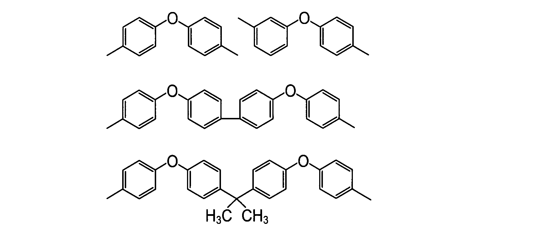
式(A):(C/D)×100/(E/F)
上記式(A)中、Cは、ポリアミド酸又はポリイミドのドープの1370cm-1の吸収ピーク高さを表し、Dは、ポリアミド酸又はポリイミドのドープの1500cm-1の吸収ピーク高さを表し、Eは、ポリイミドフィルムの1370cm-1の吸収ピーク高さを表し、Fは、ポリイミドフィルムの1500cm-1の吸収ピーク高さを表す。
シクロオレフィン樹脂(シクロオレフィンポリマー)としては、下記一般式(S)に示す構造を有する単量体の重合体又は共重合体が挙げられる。
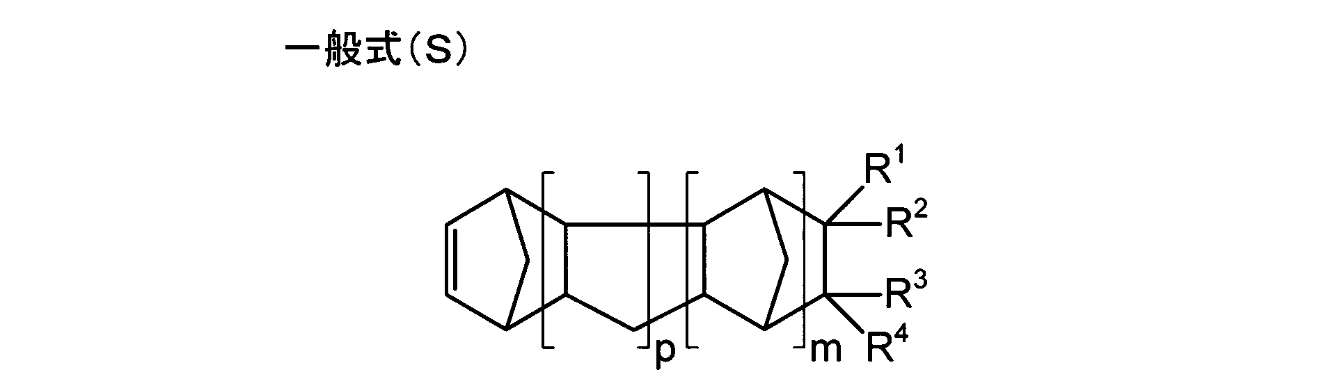
ポリアリレート樹脂は、少なくとも芳香族ジアルコール成分単位と芳香族ジカルボン酸成分単位とを含む。
芳香族ジアルコール成分単位を得るための芳香族ジアルコールは、好ましくは下記式(1)で表されるビスフェノール類、より好ましくは下記式(1’)で表されるビスフェノール類である。


芳香族ジカルボン酸成分単位を構成する芳香族ジカルボン酸は、テレフタル酸、イソフタル酸又はそれらの混合物でありうる。
ポリアリレートのガラス転移温度は、260℃以上350℃以下であることが好ましく、265℃以上300℃未満であることがより好ましく、270℃以上300℃未満であることがさらに好ましい。
ポリアリレートの固有粘度は、0.3~1.0dl/gであることが好ましく、0.4~0.9dl/gがより好ましく、0.45~0.8dl/gがさらに好ましく、0.5~0.7dl/gであることがさらに好ましい。ポリアリレートの固有粘度が0.3dl/g以上であると、樹脂組成物の分子量が一定以上となりやすく、十分な機械的特性や耐熱性を有するフィルムが得られやすい。ポリアリレートの固有粘度が1.0dl/g以下であると、製膜時の溶液粘度が過剰に高まるのを抑制しうる。
本実施形態において、流延するドープに含まれる溶媒は、良溶媒および貧溶媒を含む。良溶媒としては、ポリイミド樹脂、シクロオレフィン樹脂、ポリアリレート樹脂を溶解するものであれば、制限なく用いることができる。
貧溶媒比率={b/(a+b)}×100
ここで、
a:混合溶媒中の良溶媒の質量(g)
b:混合溶媒中の貧溶媒の質量(g)
である。
本実施形態の光学フィルムの製造において、ドープに含有させる添加剤として、微粒子、可塑剤、紫外線吸収剤、酸化防止剤、糖エステル化合物、位相差調整剤、光安定剤、帯電防止剤、剥離剤、増粘剤などを用いてもよい。以下、主要な添加剤についてのみ説明する。
本実施形態の光学フィルムには、製膜時にフィルム表面に凹凸を付与し、すべり性を確保し、安定な巻取り形状を達成するためにマット剤を含有させることが望ましい。マット剤を含有することにより、作製された光学フィルムがハンドリングされる際に、傷が付いたり、搬送性が悪化するのを抑制することもできる。
光学フィルムに添加する可塑剤として、ポリエステル樹脂を用いることができる。ポリエステル樹脂は、ジカルボン酸とジオールを重合することにより得られ、ジカルボン酸構成単位(ジカルボン酸に由来する構成単位)の70%以上が芳香族ジカルボン酸に由来し、かつジオール構成単位(ジオールに由来する構成単位)の70%以上が脂肪族ジオールに由来する。
以下、本発明の具体的な実施例について説明するが、本発明はこれらの実施例に限定されるわけではない。
(ポリイミドAの合成)
乾燥窒素ガス導入管、冷却器、トルエンを満たしたDean-Stark凝集器、撹拌機を備えた4口フラスコに、2,2-ビス(3,4-ジカルボキシフェニル)-1,1,1,3,3,3-ヘキサフルオロプロパン二無水物25.59g(57.6mmol)をN,N-ジメチルアセトアミド(134g)に加え、窒素気流下、室温で撹拌した。それに4,4′-ジアミノ-2,2′-ビス(トリフルオロメチル)ビフェニル19.2g(60mmol)を加え、80℃で6時間加熱撹拌した。その後、外温を190℃まで加熱して、イミド化に伴って発生する水をトルエンとともに共沸留去した。6時間加熱、還流、撹拌を続けたところ、水の発生は認められなくなった。引き続き、トルエンを留去しながら7時間加熱し、さらにトルエン留去後にメタノールを投入して再沈殿し、下記式で表されるポリイミドAを得た。
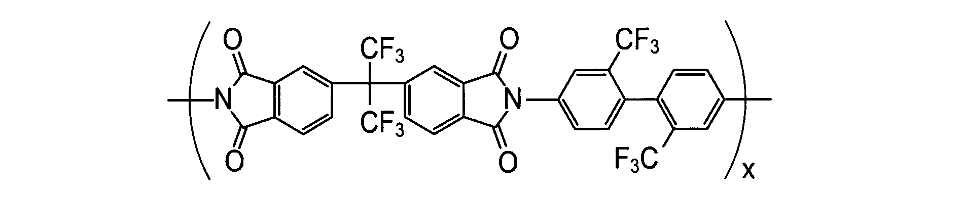
下記組成の主ドープを調製した。まず、加圧溶解タンクに混合溶媒としてテトラヒドロフラン(THF)とエタノール(EtOH)を添加した。なお、混合溶媒中のTHFの含有量は99質量%とした。当該混合溶媒の入った加圧溶解タンクに、上記調製したポリイミドAを撹拌しながら投入した。これを加熱し、撹拌しながら、完全に溶解し、これを安積濾紙(株)製の安積濾紙No.244を使用して濾過した後、残りの成分を添加し、撹拌して溶解させて、主ドープを調製した。
ポリイミドA 250.0質量部
テトラヒドロフラン 720質量部
エタノール 80質量部
微粒子:日本アエロジル(株)R812(一次粒径7nm)
2.63質量部
次いで、無端ベルト流延装置を用い、ドープを温度30℃、1500mm幅でステンレスベルト支持体上に均一に流延した。そして、ステンレスベルトの温度を30℃に制御し、ステンレスベルト支持体上で、残留溶媒量が75%になるまで溶媒を蒸発させ、支持体上に流延膜を形成した。このとき、ステンレスベルト支持体の移動速度V2を8m/minとし、流延ダイからの流延幅端部からのドープの吐出速度V1Eを10m/minとし、流延幅中央部からのドープの吐出速度V1Cを12m/minとした。なお、ドープの吐出速度V1E・V1Cについては、流延ダイのスリットギャップを流延幅方向で変化させることによって(より具体的には、スリットギャップを流延幅中央部よりも流延幅端部で広げることによって)調整した。
次いで、剥離張力180N/mで、流延膜をステンレスベルト支持体上から剥離した。そのときの残留溶媒量は22質量%であった。
剥離した流延膜を、搬送張力100N/m、乾燥時間15分間として、残留溶媒量が0.1質量%未満となる乾燥温度で乾燥させ、乾燥膜厚25μmのフィルムを得た。そして、得られたフィルムを巻き取り、赤外線ヒーターにより300℃で5分間加熱処理を行い、1500mm幅のポリイミドフィルムである光学フィルム1を得た。
流延工程において、ステンレスベルト支持体の移動速度V2、流延ダイからの流延幅端部からのドープの吐出速度V1E、および流延幅中央部からのドープの吐出速度V1Cを表1のように変更した以外は、光学フィルム1の作製と同様にして、光学フィルム2~18を作製した。なお、光学フィルム2~18の製膜においては、流延ダイの、ドープが吐出されるスリットのギャップを流延幅方向で変化させることにより、ドープの吐出速度V1Eおよび吐出速度V1Cを変化させた。つまり、流延ダイのスリットギャップを、流延幅中央部よりも流延幅端部で広げることにより、V1E<V1Cを実現し、流延幅中央部よりも流延幅端部で狭めることにより、V1E>V1Cを実現した。
ドープに含まれる樹脂をポリアリレート樹脂に変更するとともに、製膜条件を若干変更した以外は、光学フィルム1の作製と同様にして、光学フィルム19を作製した。以下、ポリアリレート樹脂の作製方法および光学フィルム1とは異なる製膜条件について説明する。
反応容器中に、水2514重量部を添加した後、水酸化ナトリウム22.7重量部、芳香族ジアルコール成分として9,9-ビス(3,5-ジメチル-4-ヒドロキシフェニル)フルオレン(BCF)35.6重量部、2,2-ビス(3,5-ジメチル-4-ヒドロキシフェニル)プロパン(TMBPA)18.5重量部、分子量調節剤としてp-tert-ブチルフェノール(PTBP)0.049重量部を溶解させ、0.34重量部の重合触媒(トリブチルベンジルアンモニウムクロライド)を添加し、撹拌した。
ポリアリレート樹脂を含むドープを、流延ダイからベルト流延装置のステンレスベルト上に均一に流延した。ステンレスベルトの長さは20mのものを用いた。このとき、ステンレスベルト支持体の移動速度V2を25m/minとし、流延ダイのスリットギャップを流延幅方向で制御して、流延ダイからの流延幅端部からのドープの吐出速度V1Eを30m/minとし、流延幅中央部からのドープの吐出速度V1Cを35m/minとした。そして、ステンレスベルトの表面温度を35℃とし、かつ流延膜に35℃の風を当てて、残留溶媒量が38%となるまで溶剤を蒸発させた後、ステンレスベルトから剥離して流延膜を得た。
流延工程において、ステンレスベルト支持体の移動速度V2、流延ダイからの流延幅端部からのドープの吐出速度V1E、および流延幅中央部からのドープの吐出速度V1Cを表1のように変更した以外は、光学フィルム19の作製と同様にして、光学フィルム20~24を作製した。なお、ドープの吐出速度V1E・V1Cについては、流延ダイのスリットギャップを流延幅方向で制御することによって調整した。
ドープに含まれる樹脂をシクロオレフィン樹脂に変更するとともに、製膜条件を若干変更した以外は、光学フィルム1の作製と同様にして、光学フィルム25を作製した。以下、シクロオレフィン樹脂の作製方法および光学フィルム1とは異なる製膜条件について説明する。
下記構造式で表される8-メトキシカルボニル-8-メチルテトラシクロ[4.4.0.12,5.17,10]-3-ドデセン50g、分子量調節剤の1-へキセン2.3g及びトルエン100gを、窒素置換した反応容器に仕込み、80℃に加熱した。これにトリエチルアルミニウム(0.6モル/L)のトルエン溶液0.09ml、メタノール変性WCl6のトルエン溶液(0.025モル/L)0.29mlを加え、80℃で3時間反応させることにより重合体を得た。次いで、得られた開環共重合体溶液をオートクレーブに入れ、さらにトルエンを100g加えた。水添触媒であるRuHCl(CO)[P(C6H5)]3をモノマー仕込み量に対して2500ppm添加し、水素ガス圧を9~10MPaとし、160~165℃にて3時間の反応を行った。反応終了後、多量のメタノール溶液に沈殿させることにより水素添加物を得た。得られた開環重合体の水素添加物であるシクロオレフィン樹脂は、ガラス転移温度(Tg)=167℃、重量平均分子量(Mw)=13.5×104、分子量分布(Mw/Mn)=3.06であった。

シクロオレフィン樹脂を含むドープを、ベルト流延装置を用い、温度22℃、2m幅でステンレスバンド支持体に流延ダイから流延した。このとき、ステンレスベルト支持体の移動速度V2を25m/minとし、流延ダイのスリットギャップを流延幅方向で制御して、流延ダイからの流延幅端部からのドープの吐出速度V1Eを30m/minとし、流延幅中央部からのドープの吐出速度V1Cを35m/minとした。そして、ステンレスバンド支持体で、残留溶剤量が30%になるまで溶媒を蒸発させ、得られた流延膜を剥離張力162N/mでステンレスバンド支持体上から剥離した。
流延工程において、ステンレスベルト支持体の移動速度V2、流延ダイからの流延幅端部からのドープの吐出速度V1E、および流延幅中央部からのドープの吐出速度V1Cを表1のように変更した以外は、光学フィルム25の作製と同様にして、光学フィルム26~30を作製した。なお、ドープの吐出速度V1E・V1Cについては、流延ダイのスリットギャップを流延幅方向で制御することによって調整した。
(位相差ムラの評価)
上述した各光学フィルムの作製時と同じ製膜条件で剥離工程まで行い、剥離工程にて、流延膜を支持体から剥離した後に流延膜を切断するとともに、流延膜の幅手方向の中央部(ここでは、幅手中心を含み、全幅の10%の幅を有する領域)と端部(ここでは、幅手エッジを含み、全幅の10%の幅を有する領域)とを切り出し、自動複屈折率計アクソスキャン(Axo Scan Mueller Matrix Polarimeter:アクソメトリックス社製)を用い、23℃55%RH(相対湿度)の環境下、590nmの波長において、三次元屈折率測定を行い、得られた平均屈折率nx、ny、nzを下記式(i)及び(ii)に代入して、面内方向のリタデーションRoおよび厚さ方向のリタデーションRthを求めた。
式(i):Ro=(nx-ny)×d(nm)
式(ii):Rth={(nx+ny)/2-nz}×d(nm)
〔式(i)及び式(ii)において、nxは、膜の面内方向において屈折率が最大になる方向xにおける屈折率を表す。nyは、膜の面内方向において、前記方向xと直交する方向yにおける屈折率を表す。nzは、膜の厚さ方向zにおける屈折率を表す。dは、膜の厚さ(nm)を表す。〕
《評価基準》
◎・・・ΔRthが1nm未満であり、位相差ムラが全くない。
○・・・ΔRthが1nm以上3nm未満であり、位相差ムラがほとんどない。
△・・・ΔRthが3nm以上5nm未満であり、位相差ムラが少しあるが、問題のない程度である。
×・・・ΔRthが5nm以上であり、位相差ムラがかなりある。
上述の製法によって製膜し、巻き取った各光学フィルムを所定長さだけ繰り出して目視で観察し、以下の基準に基づいて横段ムラ(膜厚ムラ)を評価した。なお、横段ムラは、流延時に一旦発生すると、製膜条件を変えても消失しないため、上記のように、製膜後の巻き取ったフィルムを目視観察して横段ムラを評価した。
《評価基準》
◎・・・横段ムラは全く観察されず、光学フィルムとして問題なく活用できるレベルである。
○・・・部分的に横段ムラがあるが、易接着層やハードコートなどを重ねることで、適用できるアプリケーションが限定されずに、光学フィルムとして問題なく活用できるレベルである。
△・・・部分的に横段ムラがあるが、易接着層やハードコートなどを重ねることで、適用できるアプリケーションは限定されるものの、光学フィルムとして活用できるレベルである。
×・・・目視で多くの横段ムラがあり、光学フィルムとして使用不可のレベルである。
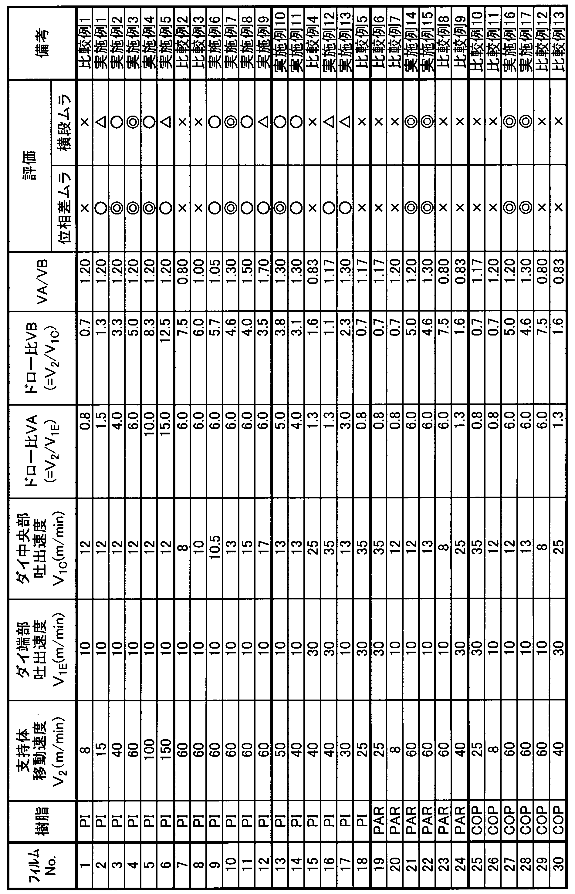
(1)V2>V1C
(2)(V2/V1E)>(V2/V1C)
(3)3<(V2/V1C)≦10
である。
(4)1.05≦(V2/V1E)/(V2/V1C)≦1.5
である。
(3’)4.6≦(V2/V1C)≦5.0
(4’)1.2≦(V2/V1E)/(V2/V1C)≦1.3
である。
以上、本発明の実施形態につき説明したが、本発明の範囲はこれに限定されるものではなく、発明の主旨を逸脱しない範囲で種々の変更を加えて実施することができる。
ポリイミド樹脂、シクロオレフィン樹脂、ポリアリレート樹脂のいずれかの樹脂と、溶媒とを含むドープを流延ダイから吐出して、移動する支持体上に流延し、流延したドープを乾燥させて流延膜を形成する流延工程と、
前記流延膜を前記支持体から剥離する剥離工程とを含み、
前記流延ダイの流延幅端部からのドープの吐出速度をV1E(m/min)とし、前記流延ダイの流延幅中央部からのドープの吐出速度をV1C(m/min)とし、前記支持体の移動速度をV2(m/min)としたとき、以下の条件式(1)および(2)を同時に満足することを特徴とする光学フィルムの製造方法;
(1)V2>V1C
(2)(V2/V1E)>(V2/V1C)
である。
(3)3<(V2/V1C)≦10
である。
(4)1.05≦(V2/V1E)/(V2/V1C)≦1.5
である。
(3’)4.6≦(V2/V1C)≦5.0
(4’)1.2≦(V2/V1E)/(V2/V1C)≦1.3
である。
2a 流延幅中央部
2b 流延幅端部
3 支持体
5 流延膜
31 スリット
Claims (5)
- 溶液流延製膜法による光学フィルムの製造方法であって、
ポリイミド樹脂、シクロオレフィン樹脂、ポリアリレート樹脂のいずれかの樹脂と、溶媒とを含むドープを流延ダイから吐出して、移動する支持体上に流延し、流延したドープを乾燥させて流延膜を形成する流延工程と、
前記流延膜を前記支持体から剥離する剥離工程とを含み、
前記流延ダイの流延幅端部からのドープの吐出速度をV1E(m/min)とし、前記流延ダイの流延幅中央部からのドープの吐出速度をV1C(m/min)とし、前記支持体の移動速度をV2(m/min)としたとき、以下の条件式(1)および(2)を同時に満足する、光学フィルムの製造方法;
(1)V2>V1C
(2)(V2/V1E)>(V2/V1C)
である。 - 以下の条件式(3)をさらに満足する、請求項1に記載の光学フィルムの製造方法;
(3)3<(V2/V1C)≦10
である。 - 以下の条件式(4)をさらに満足する、請求項2に記載の光学フィルムの製造方法;
(4)1.05≦(V2/V1E)/(V2/V1C)≦1.5
である。 - 以下の条件式(3’)および(4’)をさらに満足する、請求項1から3のいずれかに記載の光学フィルムの製造方法;
(3’)4.6≦(V2/V1C)≦5.0
(4’)1.2≦(V2/V1E)/(V2/V1C)≦1.3
である。 - 前記流延ダイの、前記ドープが吐出されるスリットのギャップを流延幅方向で変化させることにより、前記ドープの吐出速度V1Eを吐出速度V1Cよりも遅くする、請求項1から4のいずれかに記載の光学フィルムの製造方法。
Priority Applications (3)
| Application Number | Priority Date | Filing Date | Title |
|---|---|---|---|
| KR1020197010955A KR102184072B1 (ko) | 2016-10-20 | 2017-07-19 | 광학 필름의 제조 방법 |
| CN201780063795.2A CN109843533B (zh) | 2016-10-20 | 2017-07-19 | 光学膜的制造方法 |
| JP2018546149A JP6981423B2 (ja) | 2016-10-20 | 2017-07-19 | 光学フィルムの製造方法 |
Applications Claiming Priority (2)
| Application Number | Priority Date | Filing Date | Title |
|---|---|---|---|
| JP2016205769 | 2016-10-20 | ||
| JP2016-205769 | 2016-10-20 |
Publications (1)
| Publication Number | Publication Date |
|---|---|
| WO2018074019A1 true WO2018074019A1 (ja) | 2018-04-26 |
Family
ID=62018398
Family Applications (1)
| Application Number | Title | Priority Date | Filing Date |
|---|---|---|---|
| PCT/JP2017/026086 Ceased WO2018074019A1 (ja) | 2016-10-20 | 2017-07-19 | 光学フィルムの製造方法 |
Country Status (4)
| Country | Link |
|---|---|
| JP (1) | JP6981423B2 (ja) |
| KR (1) | KR102184072B1 (ja) |
| CN (1) | CN109843533B (ja) |
| WO (1) | WO2018074019A1 (ja) |
Citations (6)
| Publication number | Priority date | Publication date | Assignee | Title |
|---|---|---|---|---|
| JPH02276607A (ja) * | 1989-04-18 | 1990-11-13 | Konica Corp | 端部の厚膜を防止できるダイス |
| JP2005231185A (ja) * | 2004-02-19 | 2005-09-02 | Konica Minolta Opto Inc | 光学フィルムの製造方法及び光学フィルム |
| JP2008015118A (ja) * | 2006-07-04 | 2008-01-24 | Konica Minolta Opto Inc | 光学フィルム製造方法、それを用いて製造されたセルロースエステルフィルム、並びに、そのセルロースエステルフィルムを用いた偏光板及び液晶表示装置 |
| WO2012056619A1 (ja) * | 2010-10-26 | 2012-05-03 | コニカミノルタオプト株式会社 | 樹脂フィルムの製造方法、流延ダイ、樹脂フィルムの製造装置、樹脂フィルム、偏光板、及び液晶表示装置 |
| WO2016076057A1 (ja) * | 2014-11-10 | 2016-05-19 | コニカミノルタ株式会社 | 樹脂フィルムの製造方法 |
| WO2016076070A1 (ja) * | 2014-11-12 | 2016-05-19 | コニカミノルタ株式会社 | 樹脂フィルムの製造方法 |
Family Cites Families (9)
| Publication number | Priority date | Publication date | Assignee | Title |
|---|---|---|---|---|
| JP2717697B2 (ja) * | 1989-04-18 | 1998-02-18 | コニカ株式会社 | セルローストリアセテートフィルムの製造方法 |
| JP3903100B2 (ja) | 1999-09-01 | 2007-04-11 | 富士フイルム株式会社 | 溶液製膜方法 |
| US7011881B2 (en) * | 2000-07-25 | 2006-03-14 | Fuji Photo Film Co., Ltd. | Polymer resin film and its production |
| JP3938682B2 (ja) * | 2001-03-14 | 2007-06-27 | 富士フイルム株式会社 | 溶液製膜方法 |
| CN1332800C (zh) * | 2001-03-14 | 2007-08-22 | 富士胶片株式会社 | 流延模具、溶液制膜方法及装置 |
| US6814914B2 (en) * | 2001-05-30 | 2004-11-09 | Konica Corporation | Cellulose ester film, its manufacturing method, optical retardation film, optical compensation sheet, elliptic polarizing plate, and image display |
| JP4607795B2 (ja) * | 2005-03-07 | 2011-01-05 | 富士フイルム株式会社 | 溶液製膜方法及び減圧装置 |
| JP2010082987A (ja) * | 2008-09-30 | 2010-04-15 | Fujifilm Corp | 熱可塑性樹脂フィルムの製造方法 |
| JP2015143754A (ja) * | 2014-01-31 | 2015-08-06 | 富士フイルム株式会社 | 透明フィルム及びその製造方法、透明導電フィルム、タッチパネル、反射防止フィルム、偏光板および表示装置 |
-
2017
- 2017-07-19 WO PCT/JP2017/026086 patent/WO2018074019A1/ja not_active Ceased
- 2017-07-19 KR KR1020197010955A patent/KR102184072B1/ko active Active
- 2017-07-19 JP JP2018546149A patent/JP6981423B2/ja active Active
- 2017-07-19 CN CN201780063795.2A patent/CN109843533B/zh active Active
Patent Citations (6)
| Publication number | Priority date | Publication date | Assignee | Title |
|---|---|---|---|---|
| JPH02276607A (ja) * | 1989-04-18 | 1990-11-13 | Konica Corp | 端部の厚膜を防止できるダイス |
| JP2005231185A (ja) * | 2004-02-19 | 2005-09-02 | Konica Minolta Opto Inc | 光学フィルムの製造方法及び光学フィルム |
| JP2008015118A (ja) * | 2006-07-04 | 2008-01-24 | Konica Minolta Opto Inc | 光学フィルム製造方法、それを用いて製造されたセルロースエステルフィルム、並びに、そのセルロースエステルフィルムを用いた偏光板及び液晶表示装置 |
| WO2012056619A1 (ja) * | 2010-10-26 | 2012-05-03 | コニカミノルタオプト株式会社 | 樹脂フィルムの製造方法、流延ダイ、樹脂フィルムの製造装置、樹脂フィルム、偏光板、及び液晶表示装置 |
| WO2016076057A1 (ja) * | 2014-11-10 | 2016-05-19 | コニカミノルタ株式会社 | 樹脂フィルムの製造方法 |
| WO2016076070A1 (ja) * | 2014-11-12 | 2016-05-19 | コニカミノルタ株式会社 | 樹脂フィルムの製造方法 |
Also Published As
| Publication number | Publication date |
|---|---|
| CN109843533B (zh) | 2021-05-04 |
| KR102184072B1 (ko) | 2020-11-27 |
| CN109843533A (zh) | 2019-06-04 |
| JPWO2018074019A1 (ja) | 2019-08-15 |
| JP6981423B2 (ja) | 2021-12-15 |
| KR20190056400A (ko) | 2019-05-24 |
Similar Documents
| Publication | Publication Date | Title |
|---|---|---|
| JP6888630B2 (ja) | 光学フィルムの製造方法 | |
| JP6874759B2 (ja) | ポリイミドフィルム及びその製造方法 | |
| JP6806141B2 (ja) | ポリイミドフィルムの製造方法 | |
| JP6747023B2 (ja) | 光学フィルムの製造方法及び製造装置 | |
| WO2017169306A1 (ja) | 光学フィルムの製造方法 | |
| JP6834440B2 (ja) | ポリイミドフィルムおよび当該フィルムを用いる表示装置 | |
| WO2017010178A1 (ja) | 偏光板、その製造方法、液晶表示装置及び有機エレクトロルミネッセンス表示装置 | |
| JP2019172746A (ja) | ポリアミド酸、ポリアミド酸溶液、ポリイミド、ポリイミド膜、積層体およびフレキシブルデバイス、ならびにポリイミド膜の製造方法。 | |
| TWI670302B (zh) | 透明電極用基材薄膜及其製造方法 | |
| JP5675114B2 (ja) | 光学補償フィルム、光学補償用積層体、光学補償用偏光板、及び液晶表示装置 | |
| WO2006025263A1 (ja) | 光学フィルム、偏光板および液晶ディスプレイ | |
| JPWO2017057247A1 (ja) | ポリイミドフィルム、フレキシブルプリント基板、led照明用基板及びフレキシブルディスプレイ用前面板 | |
| JP6981424B2 (ja) | 光学フィルムの製造方法 | |
| JP6981423B2 (ja) | 光学フィルムの製造方法 | |
| JP2017185743A (ja) | ポリイミドフィルムの製造方法、及び製造装置 | |
| KR102471725B1 (ko) | 폴리이미드계 필름 | |
| JP6772519B2 (ja) | ポリイミドフィルム、その製造方法、透明導電フィルム及びタッチパネル | |
| JP2017187562A (ja) | 光学フィルムの製造方法及び製造装置 | |
| WO2024172112A1 (ja) | ポリイミド前駆体組成物、ポリイミド膜、積層体、電子デバイス、積層体の製造方法、ポリイミド膜の製造方法及び電子デバイスの製造方法 |
Legal Events
| Date | Code | Title | Description |
|---|---|---|---|
| 121 | Ep: the epo has been informed by wipo that ep was designated in this application |
Ref document number: 17862633 Country of ref document: EP Kind code of ref document: A1 |
|
| ENP | Entry into the national phase |
Ref document number: 2018546149 Country of ref document: JP Kind code of ref document: A |
|
| ENP | Entry into the national phase |
Ref document number: 20197010955 Country of ref document: KR Kind code of ref document: A |
|
| NENP | Non-entry into the national phase |
Ref country code: DE |
|
| 122 | Ep: pct application non-entry in european phase |
Ref document number: 17862633 Country of ref document: EP Kind code of ref document: A1 |