WO2018070299A1 - 帯状部材の切断方法および切断装置 - Google Patents
帯状部材の切断方法および切断装置 Download PDFInfo
- Publication number
- WO2018070299A1 WO2018070299A1 PCT/JP2017/035948 JP2017035948W WO2018070299A1 WO 2018070299 A1 WO2018070299 A1 WO 2018070299A1 JP 2017035948 W JP2017035948 W JP 2017035948W WO 2018070299 A1 WO2018070299 A1 WO 2018070299A1
- Authority
- WO
- WIPO (PCT)
- Prior art keywords
- belt
- tip
- strip
- shaped member
- cutter
- Prior art date
- Legal status (The legal status is an assumption and is not a legal conclusion. Google has not performed a legal analysis and makes no representation as to the accuracy of the status listed.)
- Ceased
Links
Images






Classifications
-
- B—PERFORMING OPERATIONS; TRANSPORTING
- B26—HAND CUTTING TOOLS; CUTTING; SEVERING
- B26D—CUTTING; DETAILS COMMON TO MACHINES FOR PERFORATING, PUNCHING, CUTTING-OUT, STAMPING-OUT OR SEVERING
- B26D3/00—Cutting work characterised by the nature of the cut made; Apparatus therefor
- B26D3/003—Cutting work characterised by the nature of the cut made; Apparatus therefor specially adapted for cutting rubber
-
- B—PERFORMING OPERATIONS; TRANSPORTING
- B26—HAND CUTTING TOOLS; CUTTING; SEVERING
- B26D—CUTTING; DETAILS COMMON TO MACHINES FOR PERFORATING, PUNCHING, CUTTING-OUT, STAMPING-OUT OR SEVERING
- B26D5/00—Arrangements for operating and controlling machines or devices for cutting, cutting-out, stamping-out, punching, perforating, or severing by means other than cutting
- B26D5/20—Arrangements for operating and controlling machines or devices for cutting, cutting-out, stamping-out, punching, perforating, or severing by means other than cutting with interrelated action between the cutting member and work feed
-
- B—PERFORMING OPERATIONS; TRANSPORTING
- B26—HAND CUTTING TOOLS; CUTTING; SEVERING
- B26D—CUTTING; DETAILS COMMON TO MACHINES FOR PERFORATING, PUNCHING, CUTTING-OUT, STAMPING-OUT OR SEVERING
- B26D5/00—Arrangements for operating and controlling machines or devices for cutting, cutting-out, stamping-out, punching, perforating, or severing by means other than cutting
- B26D5/42—Arrangements for operating and controlling machines or devices for cutting, cutting-out, stamping-out, punching, perforating, or severing by means other than cutting with interrelated action between work feed and clamp
-
- B—PERFORMING OPERATIONS; TRANSPORTING
- B26—HAND CUTTING TOOLS; CUTTING; SEVERING
- B26D—CUTTING; DETAILS COMMON TO MACHINES FOR PERFORATING, PUNCHING, CUTTING-OUT, STAMPING-OUT OR SEVERING
- B26D7/00—Details of apparatus for cutting, cutting-out, stamping-out, punching, perforating, or severing by means other than cutting
- B26D7/01—Means for holding or positioning work
- B26D7/015—Means for holding or positioning work for sheet material or piles of sheets
-
- B—PERFORMING OPERATIONS; TRANSPORTING
- B29—WORKING OF PLASTICS; WORKING OF SUBSTANCES IN A PLASTIC STATE IN GENERAL
- B29D—PRODUCING PARTICULAR ARTICLES FROM PLASTICS OR FROM SUBSTANCES IN A PLASTIC STATE
- B29D30/00—Producing pneumatic or solid tyres or parts thereof
- B29D30/06—Pneumatic tyres or parts thereof (e.g. produced by casting, moulding, compression moulding, injection moulding, centrifugal casting)
- B29D30/38—Textile inserts, e.g. cord or canvas layers, for tyres; Treatment of inserts prior to building the tyre
- B29D30/46—Cutting textile inserts to required shape
-
- B—PERFORMING OPERATIONS; TRANSPORTING
- B29—WORKING OF PLASTICS; WORKING OF SUBSTANCES IN A PLASTIC STATE IN GENERAL
- B29D—PRODUCING PARTICULAR ARTICLES FROM PLASTICS OR FROM SUBSTANCES IN A PLASTIC STATE
- B29D30/00—Producing pneumatic or solid tyres or parts thereof
- B29D30/06—Pneumatic tyres or parts thereof (e.g. produced by casting, moulding, compression moulding, injection moulding, centrifugal casting)
- B29D30/38—Textile inserts, e.g. cord or canvas layers, for tyres; Treatment of inserts prior to building the tyre
- B29D30/46—Cutting textile inserts to required shape
- B29D2030/463—Holding the textile inserts during cutting; means therefor
Definitions
- the present invention relates to a strip member cutting method and a cutting apparatus.
- one long strip member strip material
- the front end portion of the strip member is a predetermined distance from the cutter.
- the downstream side there is a step in which the belt-shaped member is cut by a cutter. A plurality of small strip pieces made by this process are joined together at different places to form one belt.
- Patent Document 2 A specific method of feeding the belt-shaped member from the upstream side to the downstream side from the cutter in the above process is described in Patent Document 2.
- a holding member that can hold the belt-like member and is movable on the upstream side of the cutter is used.
- the holding member holds the upstream portion of the belt-like member, and conveys the belt-like member such that the tip of the belt-like member is pushed downstream from the cutter.
- an object of the present invention is to provide a cutting method and a cutting device in which the band-shaped member is hardly caught during the feeding of the band-shaped member downstream from the cutter.
- the cutting method of the belt-shaped member of the embodiment is the cutting method of the belt-shaped member that cuts one after another while feeding the belt-shaped belt member for the tire belt from the upstream side to the downstream side from the cutter.
- a tip feeding device provided between the upstream and the fixed-size feeding hand that feeds the belt-like member holds the belt-like member and feeds the tip of the belt to the downstream side of the cutter, and then the belt-like member.
- the member is released and returned to the standby position before holding the belt-like member, and the tip of the belt-like member fed out for a short distance is held by a tip gripping hand provided on the downstream side of the cutter, and the belt is fed out for a short distance.
- the fixed-length feed hand holds the upstream portion of the belt-shaped member from the cutter
- the tip gripping hand and the fixed-size feed hand are:
- the belt-like member is sent out for a long distance to the downstream side, and then the belt-like member is released to return to the respective standby positions before holding the belt-like member. Is held at the standby position, and the cutter cuts, and after the cutting, the leading edge feeding device feeds the belt-like member again for a short distance.
- the belt-shaped member cutting device is a belt-shaped member cutting device that cuts one after another while feeding the belt-shaped member for the belt of the tire from the upstream side to the downstream side from the cutter.
- a cutter that cuts the belt-like member every time it is fed from the side to the downstream side, and the belt-like member fed out for a long distance is held at a standby position upstream from the cutter, and after the cut, the tip of the belt-like member A short-distance feed to the downstream side of the cutter, a tip-feed device that returns to the standby position after releasing the short-distance feed, and the belt-like shape that is provided on the downstream side of the cutter and fed short-distance.
- a tip gripping hand that returns to the upstream side of the tip gripping device, and is provided on the upstream side of the tip feed device and holds the portion of the strip-shaped member that has been fed a short distance upstream of the cutter and is synchronized with the tip gripping hand And a fixed-size feed hand that returns to the standby position before the belt-shaped member is released and then the belt-shaped member is held.
- the strip member cutting method and cutting apparatus of the embodiment since the strip member is sent out for a long distance in a state in which the tip and the upstream portion are held, the strip member is not easily caught in the middle of feeding.
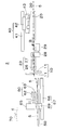
- FIG. (A) The top view of the strip
- FIG. (B) The top view of the strip piece 80.
- FIG. (C) A plan view of a plurality of strip pieces 80 arranged (code 6 is omitted).
- tip feeder 23 sends out the strip
- tip feeder 23 sent out the strip
- FIG. 1 The perspective view of the cutting device 2 when the front-end
- the direction in which the belt-shaped member 5 is sent is the downstream side, and the opposite direction is the upstream side.
- the belt manufacturing apparatus 1 shown in FIG. 1 is an arrangement in which a cutting device 2 that cuts a belt-like member 5 for a belt of a tire while feeding it from the upstream side to the downstream side and a strip piece 80 formed by cutting the belt-like member 5 are arranged.
- the conveyor 3 and the conveying apparatus 4 which conveys the strip piece 80 from the cutting device 2 to the alignment conveyor 3 are provided.
- the arrow B in FIG. 1 and FIG. 2 has shown the direction where the strip
- the strip-like member 5 cut in the embodiment is formed by covering a plurality of metal cords 6 arranged in parallel with rubber.
- the extending direction of the belt-like member 5 is the same as the extending direction of the cord 6.
- the strip-like member 5 is cut into a plurality of strip pieces 80 having a predetermined length in the cutting device 2.
- the belt-like member 5 is cut obliquely with respect to the extending direction. Therefore, as shown in FIG. 3B, the strip piece 80 is an elongated parallelogram having two cut sides 81 as one set of opposite sides and two non-cut sides 82 as another set of opposite sides.
- the plurality of strip pieces 80 are arranged on the alignment conveyor 3 so that the vicinity of the non-cutting side 82 overlaps as shown in FIG. The overlapping portions are joined to form a single belt.
- the cutting device 2 shown in FIGS. 1 and 2 includes a cutter 10 that cuts the belt-shaped member 5, a feed table 20 that is a passage of the belt-shaped member 5 on the upstream side of the cutter 10, and between the cutter 10 and the feed table 20. And the unloading table 50 serving as a place for the strip piece 80 on the downstream side of the cutter 10. As will be described in detail later, the tip feeding device 23 feeds the belt-like member 5 to the downstream side for a short distance.
- the cutting device 2 includes a fixed-size feed hand 30 and a tip gripping hand 60, each of which can hold the belt-like member 5.
- the fixed-size feed hand 30 is movable along the feed table 20 above the feed table 20.
- the tip gripping hand 60 is movable along the carry-out table 50 above the carry-out table 50.
- the fixed-size feed hand 30 and the tip gripping hand 60 feed the belt-like member 5 to the downstream side for a long distance.
- the long distance is a distance longer than the short distance.
- side walls 21 are provided on both sides of the feed table 20 in the width direction.
- the interval between the side walls 21 on both sides is the same as the width of the band-shaped member 5 or slightly wider than the width of the band-shaped member 5.
- These side walls 21 prevent the belt-like member 5 from shifting in the width direction on the feed table 20.
- the belt-like member 5 is supplied to the feed table 20 from a supply device (not shown).
- a fixed-size feed device 40 is provided above the feed table 20.
- the fixed-size feeding device 40 includes a moving unit 41 and a moving body 42 that is moved along the feeding table 20 when the moving unit 41 is operated.
- the moving means 41 is, for example, a ball screw mechanism driven by a servo motor.
- the moving body 42 is provided with an elevating means 43 and a fixed-size feeding hand 30 that can be moved up and down by the operation of the elevating means 43.
- the raising / lowering means 43 is an air cylinder, for example.
- the fixed-size feed hand 30 can suck and hold the belt-like member 5 on the feed table 20 by suction means such as magnetic suction or vacuum suction, and can release the belt-like member 5 by releasing the suction.
- the moving body 42, the lifting / lowering means 43, and the fixed-size feed hand 30 move together along the feed table 20.
- the fixed-size feed hand 30 moves between a standby position of the fixed-size feed hand 30 and a predetermined position downstream of the standby position of the fixed-size feed hand 30.
- the standby position of the fixed-size feed hand 30 is at a predetermined position on the upstream side of the feed table 20.
- the sizing feed hand 30 feeds the belt-like member 5 on the table 20 to the downstream side
- the sizing feed hand 30 is moved to a standby position on the upstream side of the feed table 20 by operating the moving means 41.
- the fixed-length feed hand 30 is lowered to the position of the belt-like member 5 by operating the elevating means 43.
- the fixed-length feed hand 30 sucks and holds the belt-like member 5.
- the moving means 41 operates to move the fixed-size feed hand 30 to the downstream side. By moving the fixed-size feed hand 30 to the downstream side, the belt-like member 5 held by the fixed-size feed hand 30 is sent to the downstream side.
- the fixed-size feed hand 30 is lifted away from the belt-like member 5 and returned to the initial standby position. By this operation, the belt-like member 5 is intermittently sent to the downstream side.
- the tip feeding device 23 includes an upper plate 26 and a lower plate 27.
- the upper plate 26 and the lower plate 27 are separated from each other.
- the tip feeding device 23 is in the closed state, the upper plate 26 and the lower plate 27 approach each other to sandwich the belt-like member 5 and hold it from above and below.
- the tip feeding device 23 is provided with an opening / closing device 28 which is a device for opening and closing the tip feeding device 23 and a moving device 29 for moving the tip feeding device 23 and the opening / closing device 28 between the upstream side and the downstream side.
- the opening / closing device 28 is, for example, an air cylinder provided such that a piston moves up and down, and an upper plate 26 is provided on the piston side, and a lower plate 27 is provided on the cylinder side. Then, when the upper plate 26 moves up and down with respect to the lower plate 27, the tip feeding device 23 composed of the upper plate 26 and the lower plate 27 opens and closes.
- the moving device 29 moves the tip feeding device 23 between a standby position of the tip feeding device 23 and a delivery position downstream of the standby position of the tip feeding device 23.
- the standby position of the tip feed device 23 is in the vicinity of the downstream end of the feed table 20.
- the delivery position is in the vicinity of the cutter 10.
- the moving device 29 is, for example, an air cylinder provided near the downstream end of the feed table 20, and moves the piston toward the downstream side.
- An opening / closing device 28 and a tip feeding device 23 are provided on the piston.
- the tip feeding device 23 moves between the standby position and the delivery position of the tip feeding device 23.
- the movable range of the tip feeding device 23 may be limited to the upstream side of the cutter 10 or may extend to the downstream side of the cutter 10.
- the tip feeding device 23 sends the strip-like member 5 to the downstream side.
- the front end feeding device 23 is open and the belt-like member 5 is placed on the lower plate 27 at the standby position of the front end feeding device 23.
- the opening / closing device 28 is operated, the tip feeding device 23 is closed, and the tip feeding device 23 holds the belt-like member 5.
- the moving device 29 is operated, the tip feeding device 23 holding the belt-like member 5 moves to the downstream side.
- the belt-like member 5 held by the tip feeding device 23 is sent to the downstream side.
- the tip feeder 23 moves to the receiving position and stops. After the stop, the tip feeding device 23 is opened and the belt-like member 5 is released. Thereafter, the tip feeding device 23 returns to the standby position of the tip feeding device 23 while being opened.
- the belt-like member 5 is intermittently sent to the downstream side.
- the cutter 10 cuts the belt-shaped member 5 obliquely with respect to the extending direction.
- the cutter 10 may be capable of adjusting the cut angle with respect to the extending direction of the belt-like member 5.
- the cutter 10 cuts the belt-like member 5 every time the belt-like member 5 is intermittently fed downstream by the fixed-size feed hand 30 and the tip gripping hand 60.
- side walls 51 are provided on both sides of the carry-out table 50 in the width direction.
- the interval between the side walls 51 on both sides is the same as the width of the strip piece 80 or slightly wider than the width of the strip piece 80.
- the distance between the side walls 51 on both sides may be adjustable.
- These side walls 51 prevent the strip piece 80 from shifting in the width direction on the carry-out table 50.
- the feed table 20 and the tip feed device 23 are substantially at the same height, and the tip gripping hand 60 and the cutter 10 operate at the same height, whereas the carry-out table 50 has these Is in a lower position.
- the unloading table 50 is movable between the receiving position for receiving the strip piece 80 and the unloading position for unloading the strip piece 80 on the downstream side of the cutter 10. The unloading position is downstream of the receiving position.
- the tip gripping hand 60 includes an upper plate 62 and a lower plate 63.
- the upper plate 62 and the lower plate 63 are separated from each other.
- the tip gripping hand 60 is in the closed state, the upper plate 62 and the lower plate 63 come close to each other and sandwich the belt-like member 5 from above and below to hold it.
- the tip gripping hand 60 is provided with an opening / closing device 65 that is a device that opens and closes the tip gripping hand 60 and a moving device 67 that moves the tip gripping hand 60 and the opening / closing device 65 between the upstream side and the downstream side. Yes.
- the opening / closing device 65 is, for example, an air cylinder provided such that the piston moves up and down, and an upper plate 62 is provided on the piston side and a lower plate 63 is provided on the cylinder side.
- an upper plate 62 is provided on the piston side
- a lower plate 63 is provided on the cylinder side.
- the moving device 67 moves the tip gripping hand 60 between the above delivery position by the tip feeding device 23 and a predetermined position downstream thereof. Between these two positions and slightly downstream of the delivery position, there is a standby position for the tip gripping hand 60.
- the moving device 67 includes a moving unit 68 and a moving body 69 that is moved along the unloading table 50 by the moving unit 68.
- the moving means 68 is, for example, a ball screw mechanism driven by a servo motor.
- the moving body 69 is provided with an opening / closing device 65 and a tip gripping hand 60. When the moving means 68 is operated, the moving body 69, the opening / closing device 65 and the tip gripping hand 60 move together.
- the tip gripping hand 60 pulls the belt-shaped member 5 downstream
- the tip gripping hand 60 moves to its standby position by operating the moving means 68.
- the moving means 68 operates to move the tip gripping hand 60 to the delivery position of the belt-like member 5.
- the opening / closing device 65 is operated, the tip gripping hand 60 holds the tip 7 of the band-like member 5 that has reached the delivery position.
- the moving means 68 is operated, the tip gripping hand 60 holding the tip 7 of the belt-like member 5 moves to the downstream side.
- the belt-like member 5 held by the tip gripping hand 60 is pulled out downstream. By this operation, the belt-like member 5 is intermittently pulled out downstream.
- the transport device 4 can move up and down.
- a horizontal movement device 70 is stretched over the cutting device 2 and the alignment conveyor 3, and the conveyance device 4 can move horizontally between the cutting device 2 and the alignment conveyor 3 by operating the horizontal movement device 70. Yes.
- the transport device 4 transports the strip piece 80 from the cutting device 2 to the alignment conveyor 3, first, the unloading table 50 on which the strip piece 80 is placed moves to the unloading position. Next, the transport device 4 moves to above the carry-out position and then descends to suck the strip piece 80 on the carry-out table 50. Next, the conveying device 4 rises and lifts the strip piece 80. Next, the horizontal movement device 70 moves the transport device 4 above the alignment conveyor 3. Next, the conveying device 4 descends. Next, the conveying device 4 separates the strip piece 80 and places it at a predetermined position on the alignment conveyor 3.
- the alignment conveyor 3 rotates in one direction by a predetermined distance and moves the strip piece 80 by a predetermined distance each time one strip piece 80 is conveyed by the conveying device 4 and placed on the alignment conveyor 3.
- the predetermined distance is such that the strip pieces 80 previously placed on the aligning conveyor 3 and the strip pieces 80 placed next on the aligning conveyor 3 can overlap each other in the vicinity of the non-cutting side 82. Determined.
- the aligning conveyor 3 is provided with a pressing device that presses the overlapping portions of the strip pieces 80. Each time the strip piece 80 is placed on the alignment conveyor 3, the pressing device presses the overlapping portion of the strip piece 80 and the strip piece 80 previously placed on the alignment conveyor 3. A plurality of strip pieces 80 are joined by pressing to complete one belt.
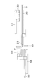
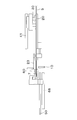
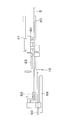
- the cutting device 2 repeats the operations depicted in FIGS. 4 to 10 to sequentially cut the belt-like member 5 while feeding the band-like member 5 from the upstream side to the downstream side from the cutter 10.
- the band-like member 5 having the tip 7 cut beforehand is placed on the feed table 20 and the tip 7 is at the position of the cutter 10. That is, it is assumed that the belt-like member 5 is in a position immediately after being cut by the cutter 10.
- the tip feeding device 23 holds the belt-like member 5 at the standby position.
- the tip 7 of the belt-like member 5 protrudes further downstream than the tip feeding device 23.
- the fixed-size feed hand 30 and the tip gripping hand 60 are in their respective standby positions, and the strip-like member 5 is separated.
- the carry-out table 50 is in the carry-out position.
- the tip feeding device 23 moves toward the delivery position and feeds the belt-like member 5 to the downstream side for a short distance.
- the tip 7 of the belt-like member 5 reaches a position downstream of the cutter 10.
- the tip gripping hand 60 moves from the standby position toward the upstream side, and the tip gripping hand 60 reaches the delivery position simultaneously with or after the tip feeding device 23 reaches the delivery position.
- the tip gripping hand 60 holds the tip 7 of the belt-like member 5. In this way, the belt-like member 5 is transferred from the tip feeding device 23 to the tip gripping hand 60.
- the tip feeding device 23 releases the belt-like member 5. Thereafter, the tip feeding device 23 returns to the standby position. Further, after the belt-like member 5 is fed out by the tip feeding device 23 for a short distance, the fixed-length feed hand 30 holds the belt-like member 5 at the standby position upstream of the cutter 10.
- the tip gripping hand 60 and the fixed-size feeding hand 30 move in a long distance to the downstream side in synchronism, and send the strip-shaped member 5 to the downstream side for a long distance.
- the movement of the tip gripping hand 60 and the fixed-size feed hand 30 in synchronization means that the tip gripping hand 60 and the fixed-size feed hand 30 move simultaneously at the same speed.
- the unloading table 50 moves to the receiving position near the cutter 10 almost simultaneously with the long-distance movement of the tip gripping hand 60 and the fixed-size feeding hand 30.
- the tip gripping hand 60 and the fixed-size feeding hand 30 release the strip-shaped member 5. Then, the front end 7 of the belt-like member 5 falls onto the carry-out table 50. The tip gripping hand 60 and the fixed-size feeding hand 30 return to their standby positions after releasing the belt-like member 5. The tip gripping hand 60 and the fixed-size feeding hand 30 are returned to their respective standby positions until the tip feeding device 23 finishes feeding the belt-like member 5 for a short distance next time. In addition, after the belt-like member 5 is fed out for a long distance and stopped, the tip feeding device 23 holds the belt-like member 5 again at the standby position. The timing at which the tip feeding device 23 holds the belt-like member 5 again is, for example, before the fixed-size feed hand 30 releases the belt-like member 5.
- the cutter 10 cuts the belt-like member 5.
- the tip feeding device 23 holds the belt-like member 5 at the standby position.
- a portion of the belt-like member 5 on the front end 7 side is cut to form a strip piece 80.
- the tip gripping hand 60 and the fixed-size feeding hand 30 may return to their respective standby positions during this cutting.
- the transport device 4 transports the strip piece 80 from the unloading table 50 to the alignment conveyor 3.
- the tip feeding device 23 that has held the belt-like member 5 at the standby position of the tip feeding device 23 during the cutting of the belt-like member 5 again holds the belt-like member 5 while holding the belt-like member 5 after the cut. Deliver a short distance downstream. Thereafter, the above operation is repeated.
- the strip-like member 5 is cut one after another to produce strip pieces 80, and the strip pieces 80 are successively conveyed to the alignment conveyor 3 and joined on the alignment conveyor 3.
- the belt for is completed.
- the tip 7 of the belt-like member 5 is held by the tip gripping hand 60, and the upstream portion of the belt-like member 5 from the cutter 10 is held by the fixed-length feed hand 30.
- the belt-like member 5 is sent out for a long distance from the cutter 10 to the downstream side. For this reason, the belt-like member 5 is hardly caught during the feeding.
- the tip feeding device 23 holds the belt-like member 5 during the cutting of the belt-like member 5, and sends the belt-like member 5 to the downstream side for a short distance after the belt-like member 5 is cut.
- the tip gripping hand 60 and the fixed-size feeding hand 30 after feeding the belt-like member 5 for a long distance can return to their standby positions.
- grip hand 60 and the fixed-size feed hand 30 can hold
- the cutting device 2 for the belt-like member 5 holds the tip 7 of the belt-like member 5 in addition to the fixed-size feed hand 30 that feeds the belt-like member 5 to the downstream side for a long distance, and is long in the downstream side.
- a tip gripping hand 60 that pulls out a distance is provided. For this reason, the belt-like member 5 is hardly caught during the feeding.
- the strip-shaped member 5 is held during the cutting of the strip-shaped member 5 and then the strip-shaped member 5 is moved downstream.
- a tip feeding device 23 for feeding out a short distance is provided. Therefore, while the front end feeding device 23 holds the belt-like member 5, the front end gripping hand 60 and the fixed length feeding hand 30 after feeding the belt-like member 5 over a long distance can return to their standby positions. As a result, the tip gripping hand 60 and the fixed-length feeding hand 30 can immediately hold the belt-like member 5 fed out by the tip feeding device 23 for a short distance. Therefore, it is possible to cut the strip-like member 5 one after another without wasting time.
- the above embodiment is an example, and the scope of the invention is not limited to this.
- Various changes, substitutions, omissions, and the like can be made to the above embodiments without departing from the scope of the invention.
- the structure of the tip feeding device 23, the fixed-size feeding device 40, the tip gripping hand 60, and the means for operating and moving them is not limited to the structure of the above-described embodiment, and the structure capable of realizing the feeding of the belt-like member 5 If it is good.
Landscapes
- Engineering & Computer Science (AREA)
- Mechanical Engineering (AREA)
- Life Sciences & Earth Sciences (AREA)
- Forests & Forestry (AREA)
- Textile Engineering (AREA)
- Tyre Moulding (AREA)
Abstract
カッターより下流側への帯状部材の送り出しにおいて引っかかりが生じにくい帯状部材の切断方法を提供する。 カッター10と、カッター10より上流側において帯状部材5を送り出す動作をする定寸送りハンド30との間の先端送り装置23が、帯状部材5の先端をカッター10よりも下流側へ短距離送り出し、短距離送り出された帯状部材5の先端をカッター10より下流側の先端把持ハンド60が保持するとともに、短距離送り出された帯状部材5のカッター10より上流側の部分を定寸送りハンド30が保持し、先端把持ハンド60と定寸送りハンド30とが、同調して帯状部材5を下流側へ長距離送り出し、長距離送り出された帯状部材5をカッター10がカットする。
Description
本発明は帯状部材の切断方法および切断装置に関する。
特許文献1に記載のように、タイヤのベルトの製造において、1本の長い帯状部材(ストリップ材)が、カッターより上流側から下流側へ送り出され、帯状部材の前端部分がカッターより所定距離だけ下流側まで到達したときに、帯状部材がカッターによりカットされる工程がある。この工程でカットされて出来た複数の小さなストリップ片は、別の場所でつなぎ合わされて、1枚のベルトとなる。
上記の工程におけるカッターより上流側から下流側への帯状部材の送り出しの具体的方法が、特許文献2に記載されている。この具体的方法では、帯状部材を保持することができ、かつ、カッターより上流側において移動可能な保持部材が使用される。この保持部材が、帯状部材の上流側の部分を保持して、帯状部材の先端をカッターより下流側へ押し出すようにして、帯状部材を搬送する。
しかし、特許文献2の方法では、帯状部材の先端が保持部材に保持されていないフリーな状態で送り出しが行われるため、帯状部材の先端がカッターの位置等に引っかかり、カッターより下流側までうまく送り出されない場合があった。
そこで本発明では、カッターより下流側への帯状部材の送り出しの途中で帯状部材の引っかかりが生じにくい切断方法および切断装置を提供することを課題とする。
実施形態の帯状部材の切断方法は、タイヤのベルト用の帯状部材をカッターより上流側から下流側へ向かって送りながら次々にカットしていく帯状部材の切断方法において、前記カッターと、前記カッターより上流側において前記帯状部材を送り出す動作をする定寸送りハンドとの間に設けられた先端送り装置が、前記帯状部材を保持してその先端をカッターよりも下流側へ短距離送り出し、その後前記帯状部材を離して前記帯状部材を保持する前の待機位置に戻り、前記短距離送り出された前記帯状部材の先端をカッターより下流側に設けられた先端把持ハンドが保持するとともに、前記短距離送り出された前記帯状部材の前記カッターより上流側の部分を前記定寸送りハンドが保持し、前記先端把持ハンドと前記定寸送りハンドとが、同調して前記帯状部材を下流側へ長距離送り出し、その後前記帯状部材を離して前記帯状部材を保持する前のそれぞれの待機位置に戻り、前記長距離送り出された前記帯状部材を前記先端送り装置がその待機位置において保持して前記カッターがカットし、カット後に前記先端送り装置が前記帯状部材を再び短距離送り出すことを特徴とする。
また、実施形態の帯状部材の切断装置は、タイヤのベルト用の帯状部材をカッターより上流側から下流側へ向かって送りながら次々にカットしていく帯状部材の切断装置において、前記帯状部材が上流側から下流側へ長距離送り出される度に前記帯状部材をカットするカッターと、前記長距離送り出された前記帯状部材を前記カッターより上流側の待機位置において保持し、前記カット後に前記帯状部材の先端をカッターよりも下流側へ短距離送り出し、前記短距離送り出した後に前記帯状部材を離して前記待機位置まで戻る先端送り装置と、前記カッターより下流側に設けられ、前記短距離送り出された前記帯状部材の先端を保持して下流側へ前記長距離引っ張り出し、その後、前記帯状部材を離して前記帯状部材を保持する前の待機位置まで戻る先端把持ハンドと、前記先端送り装置より上流側に設けられ、前記短距離送り出された前記帯状部材の前記カッターより上流側の部分を保持して前記先端把持ハンドと同調して前記帯状部材を下流側へ前記長距離送り出し、その後、前記帯状部材を離して前記帯状部材を保持する前の待機位置まで戻る定寸送りハンドとを備えることを特徴とする。
実施形態の帯状部材の切断方法および切断装置によれば、帯状部材が、その先端と上流側の部分とが保持された状態で長距離送り出されるため、帯状部材が送り出しの途中で引っかかりにくい。
実施形態について図面に基づき説明する。以下の説明において、帯状部材5が送られていく方向を下流側、その反対方向を上流側とする。
まず、ベルト製造装置1の全体構造、帯状部材5の構造および切断装置2の全体構造について説明する。
図1に示すベルト製造装置1は、タイヤのベルト用の帯状部材5を上流側から下流側へ送りながらカットする切断装置2と、帯状部材5がカットされて出来たストリップ片80が並べられる整列コンベア3と、ストリップ片80を切断装置2から整列コンベア3へ運搬する運搬装置4とを備える。なお、図1および図2における矢印Bは、帯状部材5が送られる方向を示している。
実施形態で切断される帯状部材5は、図3(a)に示すように、平行に並べられた金属製の複数のコード6がゴムで被覆されたものである。帯状部材5の延長方向はコード6の延長方向と同じである。帯状部材5は切断装置2において所定長さの複数のストリップ片80にカットされる。帯状部材5はその延長方向に対して斜めにカットされる。そのため図3(b)に示すように、ストリップ片80は、2つの切断辺81が1組の対辺、2つの非切断辺82がもう1組の対辺となる細長い平行四辺形となる。複数のストリップ片80は、整列コンベア3において、図3(c)に示すように非切断辺82近傍同士が重なり合うようにして並べられる。その重なり合った部分が接合されて、1枚のベルトとなる。
図1、図2に示す切断装置2は、帯状部材5をカットするカッター10と、カッター10よりも上流側における帯状部材5の通路である送りテーブル20と、カッター10と送りテーブル20との間に配置された先端送り装置23と、カッター10よりも下流側におけるストリップ片80の置き場となる搬出用テーブル50とを備える。後で詳細に述べるように、先端送り装置23は帯状部材5を下流側へ短距離送り出すものである。
さらに、切断装置2は、それぞれ帯状部材5を保持可能な、定寸送りハンド30および先端把持ハンド60を備える。定寸送りハンド30は送りテーブル20の上方において送りテーブル20に沿って移動可能である。先端把持ハンド60は搬出用テーブル50の上方において搬出用テーブル50に沿って移動可能である。後で詳細に述べるように、定寸送りハンド30および先端把持ハンド60は帯状部材5を下流側へ長距離送り出すものである。ここで長距離とは、前記短距離より長い距離のことである。
次に、ベルト製造装置1を構成する各部の具体的な構造について、図1および図2に基づき説明する。
図1に示すように、送りテーブル20の幅方向両側には側壁21が設けられている。両側の側壁21の間隔は、帯状部材5の幅と同じか、帯状部材5の幅よりも若干広い。これらの側壁21は、送りテーブル20上で帯状部材5がその幅方向にずれることを防ぐ。送りテーブル20には図示しない供給装置から帯状部材5が供給される。
図2に示すように、送りテーブル20の上方には定寸送り装置40が設けられている。定寸送り装置40は、移動手段41と、移動手段41が稼働することによって送りテーブル20に沿って移動させられる移動体42とを備える。移動手段41は、例えば、サーボモータにより駆動されるボールネジ機構である。移動体42には昇降手段43と昇降手段43の稼働により昇降できる定寸送りハンド30とが取り付けられている。昇降手段43は例えばエアシリンダである。定寸送りハンド30は、磁気吸着や真空吸着等の吸着手段により送りテーブル20上の帯状部材5を吸着し保持することができ、また、吸着を解除して帯状部材5を離すことができる。移動手段41が稼働すると、移動体42、昇降手段43、および定寸送りハンド30は一体となって送りテーブル20に沿って移動する。定寸送りハンド30は、定寸送りハンド30の待機位置と、定寸送りハンド30の待機位置よりも下流側の所定位置との間で移動する。定寸送りハンド30の待機位置は、送りテーブル20の上流側の所定位置にある。
定寸送りハンド30がテーブル20上の帯状部材5を下流側へ送り出す場合、まず、移動手段41が稼働することによって定寸送りハンド30が送りテーブル20の上流側にある待機位置に移動させられる。次に、昇降手段43が稼働することによって定寸送りハンド30が帯状部材5の位置まで下降させられる。次に、定寸送りハンド30が帯状部材5を吸着し保持する。次に、移動手段41が稼働して定寸送りハンド30が下流側へ移動する。定寸送りハンド30が下流側へ移動することで、定寸送りハンド30に保持されている帯状部材5が下流側へ送り出される。定寸送りハンド30が予め定められた所定距離移動して停止した後、定寸送りハンド30は帯状部材5を離して上昇し、始めの待機位置へ戻る。この動作により、帯状部材5が間欠的に下流側へ送り出される。
図2に示すように、先端送り装置23は上プレート26および下プレート27からなる。先端送り装置23が開状態のとき、上プレート26および下プレート27は離間している。一方、先端送り装置23が閉状態のとき、上プレート26および下プレート27は近接して帯状部材5を挟み込み、これを上下から保持する。
先端送り装置23には、これを開閉する装置である開閉装置28と、先端送り装置23および開閉装置28を上流側と下流側との間で移動させる移動装置29とが設けられている。
開閉装置28は、例えば、ピストンが上下動するように設けられたエアシリンダであり、ピストン側に上プレート26が、シリンダ側に下プレート27が、それぞれ設けられている。そして、下プレート27に対して上プレート26が上下動することにより、上プレート26と下プレート27とからなる先端送り装置23が開閉する。
移動装置29は、先端送り装置23を、先端送り装置23の待機位置と、先端送り装置23の待機位置よりも下流側の受け渡し位置との間で移動させる。先端送り装置23の待機位置は送りテーブル20の下流側の端部近傍にある。受け渡し位置はカッター10近傍にある。移動装置29は、例えば、送りテーブル20の下流側の端部付近に設けられたエアシリンダであり、ピストンを下流側へ向かって動かすものである。そして、そのピストンに開閉装置28および先端送り装置23が設けられている。この構造の場合、移動装置29であるエアシリンダが稼働することにより、先端送り装置23が、先端送り装置23の待機位置と受け渡し位置との間を移動する。なお、先端送り装置23の移動可能な範囲は、カッター10より上流側に限られても良いし、カッター10より下流側にまで及んでいても良い。
先端送り装置23が帯状部材5を下流側へ送り出す場合の動作を説明する。まず先端送り装置23の待機位置において、先端送り装置23が開いており下プレート27上に帯状部材5が置かれているものとする。次に、開閉装置28が稼働することにより先端送り装置23が閉じ、先端送り装置23が帯状部材5を保持する。次に、移動装置29が稼働することにより、帯状部材5を保持した先端送り装置23が下流側へ移動する。先端送り装置23が下流側へ移動することで、先端送り装置23に保持されている帯状部材5が下流側へ送り出される。先端送り装置23は受け取り位置まで移動して停止する。停止後、先端送り装置23が開いて、帯状部材5が離される。その後、先端送り装置23は、開いたまま、先端送り装置23の待機位置へ戻る。この動作により、帯状部材5が間欠的に下流側へ送り出される。
カッター10は帯状部材5をその延長方向に対して斜めにカットするものである。カッター10の構造は限定されないが、例えば図2に示すように、上下一対の刃11からなるものである。カッター10は、帯状部材5の延長方向に対するカット角を調整可能なものであっても良い。カッター10は、帯状部材5が定寸送りハンド30および先端把持ハンド60によって間欠的に下流側へ送り出されるたびに、帯状部材5をカットする。
図1に示すように、搬出用テーブル50の幅方向両側には側壁51が設けられている。両側の側壁51の間隔は、ストリップ片80の幅と同じか、ストリップ片80の幅よりも若干広い。両側の側壁51の間隔は調整可能であっても良い。これらの側壁51は、搬出用テーブル50上でストリップ片80がその幅方向にずれることを防ぐ。図2に示すように、送りテーブル20および先端送り装置23がほぼ同じ高さにあり先端把持ハンド60およびカッター10がこれらと同じ高さの所で動作するのに対し、搬出用テーブル50はこれらよりも低い位置にある。搬出用テーブル50は、カッター10よりも下流側において、ストリップ片80を受け取る受け取り位置とストリップ片80を搬出する搬出位置との間で移動可能となっている。搬出位置は受け取り位置よりも下流側にある。
図2に示すように、先端把持ハンド60は上プレート62および下プレート63を備える。先端把持ハンド60が開状態のとき、上プレート62および下プレート63は離間している。一方、先端把持ハンド60が閉状態のとき、上プレート62および下プレート63は近接して帯状部材5を上下から挟み、これを保持する。
先端把持ハンド60には、先端把持ハンド60を開閉する装置である開閉装置65と、先端把持ハンド60および開閉装置65を上流側と下流側との間で移動させる移動装置67とが設けられている。
開閉装置65は、例えば、ピストンが上下動するように設けられたエアシリンダであり、ピストン側に上プレート62が、シリンダ側に下プレート63が、それぞれ設けられている。この構造の場合、下プレート63に対して上プレート62が上下動することにより、上プレート62と下プレート63とからなる先端把持ハンド60が開閉する。
移動装置67は、先端把持ハンド60を、先端送り装置23による上記の受け渡し位置と、それより下流側の所定位置との間で移動させる。これら2つの位置の間であって受け渡し位置より僅かに下流側には、先端把持ハンド60の待機位置がある。移動装置67は、移動手段68と、移動手段68によって搬出用テーブル50に沿って移動させられる移動体69とを備える。移動手段68は、例えば、サーボモータにより駆動されるボールネジ機構である。移動体69に開閉装置65および先端把持ハンド60が設けられており、移動手段68が稼働すると、移動体69、開閉装置65および先端把持ハンド60が一体となって移動する。
先端把持ハンド60が帯状部材5を下流側へ引っ張り出す場合、まず、移動手段68が稼働することにより、先端把持ハンド60がその待機位置へ移動する。次に、先端送り装置23が帯状部材5を下流側へ送り出すと同時または送り出した後、移動手段68が稼働することにより、先端把持ハンド60が帯状部材5の受け渡し位置へ移動する。次に、開閉装置65が稼働することにより、受け渡し位置に到達していた帯状部材5の先端7を先端把持ハンド60が保持する。次に、移動手段68が稼働することにより、帯状部材5の先端7を保持した先端把持ハンド60が下流側へ移動する。先端把持ハンド60が下流側へ移動することで、先端把持ハンド60に保持されている帯状部材5が下流側へ引っ張り出される。この動作により、帯状部材5が間欠的に下流側へ引っ張り出される。
図1に示す運搬装置4は、磁気吸着や真空吸着等の吸着手段を有し、ストリップ片80を吸着したり離したりできる構造となっている。さらに運搬装置4は上下動可能となっている。切断装置2と整列コンベア3とに水平移動装置70が掛け渡されており、水平移動装置70が稼働することにより運搬装置4が切断装置2と整列コンベア3との間で水平移動可能となっている。
運搬装置4がストリップ片80を切断装置2から整列コンベア3へ運搬する場合、まず、ストリップ片80を載せた搬出用テーブル50が搬出位置に移動する。次に、運搬装置4が、搬出位置の上方まで移動し、次に下降して搬出用テーブル50上のストリップ片80を吸着する。次に運搬装置4が上昇しストリップ片80を持ち上げる。次に、水平移動装置70が運搬装置4を整列コンベア3の上方に移動させる。次に運搬装置4が下降する。次に、運搬装置4がストリップ片80を離して整列コンベア3上の所定の位置に置く。
整列コンベア3は、運搬装置4により1つのストリップ片80が運搬されて来て整列コンベア3上に置かれるたびに、所定距離だけ一方向へ回り、ストリップ片80を所定距離だけ移動させる。この所定距離は、先に整列コンベア3上に置かれていたストリップ片80と、その次に整列コンベア3上に置かれたストリップ片80との、非切断辺82近傍同士が重なり合うことができるように、定められる。整列コンベア3には、ストリップ片80同士の重なり合う部分を押圧する押圧装置が設けられている。ストリップ片80が整列コンベア3上に置かれるたびに、そのストリップ片80とその前に整列コンベア3上に置かれていたストリップ片80との重なり合う部分を、押圧装置が押圧する。複数のストリップ片80が押圧により接合されて1枚のベルトが完成する。
次に、切断装置2による帯状部材5の切断方法およびベルト製造装置1によるベルトの製造方法について、図4~図10に基づき説明する。切断装置2は、図4~図10に描かれている動作を繰り返すことにより、帯状部材5をカッター10より上流側から下流側へ向かって送りながら次々にカットしていく。
図4に示すように、あらかじめ、先端7がカットされた帯状部材5が送りテーブル20上に置かれ、その先端7がカッター10の位置にあるものとする。つまり、帯状部材5が、カッター10によりカットされた直後の位置にあるものとする。このとき先端送り装置23はその待機位置において帯状部材5を保持している。また帯状部材5の先端7は先端送り装置23よりも下流側へ突出している。また、定寸送りハンド30および先端把持ハンド60は、それぞれの待機位置にあり、帯状部材5を離している。また、搬出用テーブル50は搬出位置にある。
次に、先端送り装置23が受け渡し位置へ向かって移動し、帯状部材5を下流側へ短距離送り出す。図5に示すように、先端送り装置23が受け渡し位置に到達すると、帯状部材5の先端7がカッター10よりも下流側の位置へ到達する。また、先端把持ハンド60が待機位置から上流側へ向かって移動し、先端送り装置23が受け渡し位置に到達すると同時にまたはその後、先端把持ハンド60も受け渡し位置へ到達する。
次に、図6に示すように、先端把持ハンド60が帯状部材5の先端7を保持する。このようにして、先端送り装置23から先端把持ハンド60へ帯状部材5が受け渡される。
次に、図7に示すように、先端送り装置23が帯状部材5を離す。その後、先端送り装置23は待機位置へ戻る。また、帯状部材5が先端送り装置23によって短距離送り出された後、カッター10より上流側では、定寸送りハンド30がその待機位置において帯状部材5を保持する。
次に、図8に示すように、先端把持ハンド60と定寸送りハンド30とが同調して下流側へ長距離移動し、帯状部材5を下流側へ長距離送り出す。ここで、先端把持ハンド60と定寸送りハンド30とが同調して移動するとは、先端把持ハンド60と定寸送りハンド30とが同時に同じ速度で移動することである。先端把持ハンド60と定寸送りハンド30とが長距離移動するとほぼ同時に、搬出用テーブル50がカッター10の近くの受け取り位置へ移動する。
次に、図9に示すように、先端把持ハンド60および定寸送りハンド30が帯状部材5を離す。すると帯状部材5の先端7が搬出用テーブル50の上へ落ちる。先端把持ハンド60および定寸送りハンド30は、帯状部材5を離した後、それぞれの待機位置へ戻る。先端把持ハンド60および定寸送りハンド30は、次に先端送り装置23が帯状部材5を短距離送り出し終えるまでに、それぞれの待機位置へ戻っている。また、帯状部材5が長距離送り出されて停止した後、先端送り装置23はその待機位置において再び帯状部材5を保持する。先端送り装置23が再び帯状部材5を保持するタイミングは、例えば、定寸送りハンド30が帯状部材5を離す前である。
次に、図10に示すように、カッター10が帯状部材5をカットする。カット中は先端送り装置23がその待機位置において帯状部材5を保持している。帯状部材5の先端7側の部分が、カットされることによりストリップ片80となる。先端把持ハンド60および定寸送りハンド30はこのカット中にそれぞれの待機位置へ戻る動作をしていても良い。
カット後のストリップ片80は、保持されていないため、受け取り位置に移動を完了していた搬出用テーブル50の上へ落ちる。搬出用テーブル50は、落ちてきたストリップ片80を受け取った後、受け取り位置よりも下流側の搬出位置へ移動して停止する。搬出用テーブル50が停止した後、運搬装置4が搬出用テーブル50から整列コンベア3へストリップ片80を運搬する。
その後、以上の動作が繰り返される。具体的には、帯状部材5のカット中に先端送り装置23の待機位置において帯状部材5を保持していた先端送り装置23は、カット後も帯状部材5を保持したまま、再び帯状部材5を下流側へ短距離送り出す。その後は以上の動作が繰り返される。
以上の動作が繰り返されることにより、次々に帯状部材5がカットされてストリップ片80が製造され、それらのストリップ片80が次々に整列コンベア3へ運搬されて整列コンベア3上で接合されて、タイヤ用のベルトが完成する。
実施形態の帯状部材5の切断方法によれば、帯状部材5の先端7が先端把持ハンド60に保持され、帯状部材5のカッター10より上流側の部分が定寸送りハンド30に保持された状態で、帯状部材5がカッター10より下流側へ長距離送り出される。そのため、送り出しの途中で帯状部材5の引っかかりが生じにくい。
しかも、先端送り装置23が、帯状部材5のカット中に帯状部材5を保持し、帯状部材5のカット後に帯状部材5を下流側へ短距離送り出す。このように先端送り装置23が帯状部材5を保持している間に、帯状部材5を長距離送り出した後の先端把持ハンド60および定寸送りハンド30がそれぞれの待機位置に戻ることができる。そして、先端把持ハンド60および定寸送りハンド30が、先端送り装置23によって短距離送り出された帯状部材5を、すぐに保持することができる。このようにして、時間を無駄にすることなく、次々に帯状部材5をカットすることが可能となる。
また、実施形態の帯状部材5の切断装置2は、帯状部材5を下流側へ長距離送り出す動作をする定寸送りハンド30の他に、帯状部材5の先端7を保持して下流側へ長距離引っ張り出す先端把持ハンド60を備える。そのため、送り出しの途中で帯状部材5の引っかかりが生じにくい。
しかも、帯状部材5を下流側へ長距離送り出す動作をする先端把持ハンド60および定寸送りハンド30の他に、帯状部材5のカット中に帯状部材5を保持しその後帯状部材5を下流側へ短距離送り出す先端送り装置23が設けられている。そのため、先端送り装置23が帯状部材5を保持している間に、帯状部材5を長距離送り出した後の先端把持ハンド60および定寸送りハンド30がそれぞれの待機位置に戻ることができる。その結果、先端把持ハンド60および定寸送りハンド30は、先端送り装置23によって短距離送り出された帯状部材5を直ちに保持することができる。従って、時間を無駄にすることなく、次々に帯状部材5をカットすることが可能となる。
以上の実施形態は例示であって、発明の範囲はこれに限定されない。以上の実施形態に対して、発明の要旨を逸脱しない範囲で、様々な変更、置換、省略等を行うことができる。例えば、先端送り装置23、定寸送り装置40および先端把持ハンド60ならびにそれらを動作、移動させる手段の構造は、上記実施形態の構造に限定されず、上記の帯状部材5の送り出しを実現できる構造であれば良い。
1…ベルト製造装置、2…切断装置、3…整列コンベア、4…運搬装置、5…帯状部材、6…コード、7…先端、10…カッター、11…刃、20…送りテーブル、21…側壁、23…先端送り装置、26…上プレート、27…下プレート、28…開閉装置、29…移動装置、30…定寸送りハンド、40…定寸送り装置、41…移動手段、42…移動体、43…昇降手段、50…搬出用テーブル、51…側壁、60…先端把持ハンド、62…上プレート、63…下プレート、65…開閉装置、67…移動装置、68…移動手段、69…移動体、70…水平移動装置、80…ストリップ片、81…切断辺、82…非切断辺
Claims (7)
- タイヤのベルト用の帯状部材をカッターより上流側から下流側へ向かって送りながら次々にカットしていく帯状部材の切断方法において、
前記カッターと、前記カッターより上流側において前記帯状部材を送り出す動作をする定寸送りハンドとの間に設けられた先端送り装置が、前記帯状部材を保持してその先端をカッターよりも下流側へ短距離送り出し、その後前記帯状部材を離して前記帯状部材を保持する前の待機位置に戻り、
前記短距離送り出された前記帯状部材の先端をカッターより下流側に設けられた先端把持ハンドが保持するとともに、前記短距離送り出された前記帯状部材の前記カッターより上流側の部分を前記定寸送りハンドが保持し、
前記先端把持ハンドと前記定寸送りハンドとが、同調して前記帯状部材を下流側へ長距離送り出し、その後前記帯状部材を離して前記帯状部材を保持する前のそれぞれの待機位置に戻り、
前記長距離送り出された前記帯状部材を前記先端送り装置がその待機位置において保持して前記カッターがカットし、カット後に前記先端送り装置が前記帯状部材を再び短距離送り出す、
帯状部材の切断方法。 - 前記先端送り装置は、前記帯状部材を保持して待機位置から受け渡し位置まで移動することによって前記帯状部材を短距離送り出し、
前記先端送り装置が受け渡し位置に到達すると同時にまたはその後、前記先端把持ハンドが受け渡し位置に到達し、前記先端送り装置から前記先端把持ハンドへ前記帯状部材が受け渡され、
前記先端把持ハンドは、前記帯状部材を保持して受け渡し位置から下流側へ移動することによって前記帯状部材を長距離送り出す、
請求項1に記載の帯状部材の切断方法。 - 前記帯状部材が長距離送り出された後、前記定寸送りハンドが前記帯状部材を離す前に、前記先端送り装置がその待機位置において前記帯状部材を保持する、請求項1又は2に記載の帯状部材の切断方法。
- 前記先端把持ハンドおよび前記定寸送りハンドは、前記帯状部材を長距離送り出して離した後、前記帯状部材のカット中に、それぞれの待機位置に戻る、請求項1~3のいずれか1項に記載の帯状部材の切断方法。
- 前記先端送り装置は、前記帯状部材のカット中に前記帯状部材を保持しており、カット後も前記帯状部材を保持したまま前記帯状部材を短距離送り出す、請求項1~4のいずれか1項に記載の帯状部材の切断方法。
- 前記先端送り装置が前記帯状部材を短距離送り出すステップと、前記先端把持ハンドと前記定寸送りハンドとが前記帯状部材を長距離送り出すステップと、前記帯状部材を前記先端送り装置が保持して前記カッターがカットするステップとを繰り返す、請求項1~5のいずれか1項に記載の帯状部材の切断方法。
- タイヤのベルト用の帯状部材をカッターより上流側から下流側へ向かって送りながら次々にカットしていく帯状部材の切断装置において、
前記帯状部材が上流側から下流側へ長距離送り出される度に前記帯状部材をカットするカッターと、
前記長距離送り出された前記帯状部材を前記カッターより上流側の待機位置において保持し、前記カット後に前記帯状部材の先端をカッターよりも下流側へ短距離送り出し、前記短距離送り出した後に前記帯状部材を離して前記待機位置まで戻る先端送り装置と、
前記カッターより下流側に設けられ、前記短距離送り出された前記帯状部材の先端を保持して下流側へ前記長距離引っ張り出し、その後、前記帯状部材を離して前記帯状部材を保持する前の待機位置まで戻る先端把持ハンドと、
前記先端送り装置より上流側に設けられ、前記短距離送り出された前記帯状部材の前記カッターより上流側の部分を保持して前記先端把持ハンドと同調して前記帯状部材を下流側へ前記長距離送り出し、その後、前記帯状部材を離して前記帯状部材を保持する前の待機位置まで戻る定寸送りハンドと、
を備える帯状部材の切断装置。
Priority Applications (1)
| Application Number | Priority Date | Filing Date | Title |
|---|---|---|---|
| US16/331,628 US11045967B2 (en) | 2016-10-13 | 2017-10-03 | Cutting method and cutting device for strip member |
Applications Claiming Priority (2)
| Application Number | Priority Date | Filing Date | Title |
|---|---|---|---|
| JP2016201589A JP6702843B2 (ja) | 2016-10-13 | 2016-10-13 | 帯状部材の切断方法および切断装置 |
| JP2016-201589 | 2016-10-13 |
Publications (1)
| Publication Number | Publication Date |
|---|---|
| WO2018070299A1 true WO2018070299A1 (ja) | 2018-04-19 |
Family
ID=61905410
Family Applications (1)
| Application Number | Title | Priority Date | Filing Date |
|---|---|---|---|
| PCT/JP2017/035948 Ceased WO2018070299A1 (ja) | 2016-10-13 | 2017-10-03 | 帯状部材の切断方法および切断装置 |
Country Status (3)
| Country | Link |
|---|---|
| US (1) | US11045967B2 (ja) |
| JP (1) | JP6702843B2 (ja) |
| WO (1) | WO2018070299A1 (ja) |
Cited By (1)
| Publication number | Priority date | Publication date | Assignee | Title |
|---|---|---|---|---|
| JP2022547868A (ja) * | 2019-09-04 | 2022-11-16 | ザ スティーラスティック カンパニー リミテッド ライアビリティ カンパニー | 様々なタイヤベルトサイズのための移送ツーリング |
Families Citing this family (1)
| Publication number | Priority date | Publication date | Assignee | Title |
|---|---|---|---|---|
| CN114131684A (zh) * | 2021-12-02 | 2022-03-04 | 天长市康美达新型绝热材料有限公司 | 一种岩棉条切削设备 |
Citations (4)
| Publication number | Priority date | Publication date | Assignee | Title |
|---|---|---|---|---|
| JP2001009929A (ja) * | 1999-06-28 | 2001-01-16 | Yokohama Rubber Co Ltd:The | ベルト部材の端尺除去方法及びその装置 |
| JP2005193328A (ja) * | 2004-01-06 | 2005-07-21 | Bridgestone Corp | 帯状部材の定長切断搬出方法および装置 |
| WO2006103861A1 (ja) * | 2005-03-29 | 2006-10-05 | Toyo Tire & Rubber Co., Ltd. | タイヤ用ベルトの製造方法及び装置 |
| JP2015098083A (ja) * | 2013-11-19 | 2015-05-28 | カール オイゲン フィッシャー ゲゼルシャフト ミット ベシュレンクテル ハフツングKarl Eugen Fischer Gesellschaft mit beschraenkter Haftung | 接着性のある薄いバンド、特にコードバンドを切断する切断装置 |
Family Cites Families (2)
| Publication number | Priority date | Publication date | Assignee | Title |
|---|---|---|---|---|
| JP2616765B2 (ja) * | 1986-04-18 | 1997-06-04 | 株式会社 バルダン | タオル生地の切断装置 |
| WO2007010592A1 (ja) | 2005-07-15 | 2007-01-25 | Toyo Tire & Rubber Co., Ltd. | ベルト部材の製造方法 |
-
2016
- 2016-10-13 JP JP2016201589A patent/JP6702843B2/ja active Active
-
2017
- 2017-10-03 US US16/331,628 patent/US11045967B2/en active Active
- 2017-10-03 WO PCT/JP2017/035948 patent/WO2018070299A1/ja not_active Ceased
Patent Citations (4)
| Publication number | Priority date | Publication date | Assignee | Title |
|---|---|---|---|---|
| JP2001009929A (ja) * | 1999-06-28 | 2001-01-16 | Yokohama Rubber Co Ltd:The | ベルト部材の端尺除去方法及びその装置 |
| JP2005193328A (ja) * | 2004-01-06 | 2005-07-21 | Bridgestone Corp | 帯状部材の定長切断搬出方法および装置 |
| WO2006103861A1 (ja) * | 2005-03-29 | 2006-10-05 | Toyo Tire & Rubber Co., Ltd. | タイヤ用ベルトの製造方法及び装置 |
| JP2015098083A (ja) * | 2013-11-19 | 2015-05-28 | カール オイゲン フィッシャー ゲゼルシャフト ミット ベシュレンクテル ハフツングKarl Eugen Fischer Gesellschaft mit beschraenkter Haftung | 接着性のある薄いバンド、特にコードバンドを切断する切断装置 |
Cited By (3)
| Publication number | Priority date | Publication date | Assignee | Title |
|---|---|---|---|---|
| JP2022547868A (ja) * | 2019-09-04 | 2022-11-16 | ザ スティーラスティック カンパニー リミテッド ライアビリティ カンパニー | 様々なタイヤベルトサイズのための移送ツーリング |
| US12179449B2 (en) | 2019-09-04 | 2024-12-31 | The Steelastic Company, Llc | Transfer tooling for varying tire belt sizes |
| JP7762647B2 (ja) | 2019-09-04 | 2025-10-30 | ザ スティーラスティック カンパニー リミテッド ライアビリティ カンパニー | 様々なタイヤベルトサイズのための移送ツーリング |
Also Published As
| Publication number | Publication date |
|---|---|
| JP2018062125A (ja) | 2018-04-19 |
| US20190358842A1 (en) | 2019-11-28 |
| JP6702843B2 (ja) | 2020-06-03 |
| US11045967B2 (en) | 2021-06-29 |
Similar Documents
| Publication | Publication Date | Title |
|---|---|---|
| JP5364160B2 (ja) | 裁断片積層体を取り巻く帯封を切断する方法と装置 | |
| CN107710905A (zh) | 带切断处理装置及处理方法 | |
| KR101865601B1 (ko) | 판 유리 할단 장치 | |
| CN111771430A (zh) | 带自动装填装置 | |
| JP6702843B2 (ja) | 帯状部材の切断方法および切断装置 | |
| CN110402241B (zh) | 玻璃板的制造方法及制造装置 | |
| JP6008684B2 (ja) | 包装袋供給装置 | |
| CN104275768A (zh) | 一种卧式注塑机全自动送嵌片系统 | |
| JP2015508741A (ja) | スライス食品を分離して積み重ねるための方法及び装置 | |
| CN103991578A (zh) | 一种送料装置及食品包装线 | |
| US10946608B2 (en) | Cornet bending machine with independent motion control system from mechanics | |
| CN113182408B (zh) | 一种小型扳边机及其工作方法 | |
| CN102990362B (zh) | 集装箱前墙板自动生产系统 | |
| KR101431784B1 (ko) | 마감테이프 처리장치 및 이를 포함하는 캐리어 권취장치 | |
| US10493646B2 (en) | Cutting station for a tire building machine | |
| JP6821915B2 (ja) | ラップラウンドケーサ | |
| TW200304871A (en) | Feeding and aligning device for a folder-gluer | |
| US4586916A (en) | Corrugated carton separator | |
| JPH1017172A (ja) | 積層紙の一枚切り出し方法および装置並びにその装置を用いたフレームスタッカー | |
| US4059193A (en) | Panel feeder | |
| CN108137250A (zh) | 片状产品供给装置 | |
| US3880272A (en) | Transfer conveyor | |
| JP2020037157A (ja) | 箔押し機用給排紙方法および装置 | |
| JP5212866B2 (ja) | シート状食品用抜き型装置 | |
| JP2008297081A (ja) | ワーク搬送装置 |
Legal Events
| Date | Code | Title | Description |
|---|---|---|---|
| 121 | Ep: the epo has been informed by wipo that ep was designated in this application |
Ref document number: 17860374 Country of ref document: EP Kind code of ref document: A1 |
|
| NENP | Non-entry into the national phase |
Ref country code: DE |
|
| 122 | Ep: pct application non-entry in european phase |
Ref document number: 17860374 Country of ref document: EP Kind code of ref document: A1 |