WO2018066644A1 - タービン翼の製造方法 - Google Patents
タービン翼の製造方法 Download PDFInfo
- Publication number
- WO2018066644A1 WO2018066644A1 PCT/JP2017/036267 JP2017036267W WO2018066644A1 WO 2018066644 A1 WO2018066644 A1 WO 2018066644A1 JP 2017036267 W JP2017036267 W JP 2017036267W WO 2018066644 A1 WO2018066644 A1 WO 2018066644A1
- Authority
- WO
- WIPO (PCT)
- Prior art keywords
- base material
- temperature
- coat
- brazing
- turbine blade
- Prior art date
Links
- 238000004519 manufacturing process Methods 0.000 title claims abstract description 34
- 239000000463 material Substances 0.000 claims abstract description 192
- 238000005219 brazing Methods 0.000 claims abstract description 80
- 238000001816 cooling Methods 0.000 claims abstract description 38
- 238000000034 method Methods 0.000 claims description 61
- 238000010438 heat treatment Methods 0.000 claims description 57
- 230000008569 process Effects 0.000 claims description 44
- 238000010583 slow cooling Methods 0.000 claims description 30
- 230000032683 aging Effects 0.000 claims description 25
- 230000003647 oxidation Effects 0.000 claims description 14
- 238000007254 oxidation reaction Methods 0.000 claims description 14
- 239000000112 cooling gas Substances 0.000 claims description 10
- 239000007769 metal material Substances 0.000 claims description 9
- 230000015572 biosynthetic process Effects 0.000 claims description 6
- 238000010791 quenching Methods 0.000 claims description 2
- 230000000171 quenching effect Effects 0.000 claims description 2
- 238000002844 melting Methods 0.000 abstract description 2
- 230000008018 melting Effects 0.000 abstract description 2
- 239000000758 substrate Substances 0.000 abstract 6
- 238000000137 annealing Methods 0.000 abstract 2
- 239000006104 solid solution Substances 0.000 abstract 1
- 230000000052 comparative effect Effects 0.000 description 20
- 239000000956 alloy Substances 0.000 description 11
- 230000004048 modification Effects 0.000 description 8
- 238000012986 modification Methods 0.000 description 8
- 229910045601 alloy Inorganic materials 0.000 description 7
- 238000001000 micrograph Methods 0.000 description 7
- 238000001556 precipitation Methods 0.000 description 7
- 239000011248 coating agent Substances 0.000 description 6
- 238000000576 coating method Methods 0.000 description 6
- 230000008859 change Effects 0.000 description 5
- 230000000694 effects Effects 0.000 description 5
- 239000007789 gas Substances 0.000 description 5
- 238000005266 casting Methods 0.000 description 4
- 230000006872 improvement Effects 0.000 description 4
- 239000000203 mixture Substances 0.000 description 4
- 238000007750 plasma spraying Methods 0.000 description 4
- 239000012720 thermal barrier coating Substances 0.000 description 4
- 230000009467 reduction Effects 0.000 description 3
- XKRFYHLGVUSROY-UHFFFAOYSA-N Argon Chemical compound [Ar] XKRFYHLGVUSROY-UHFFFAOYSA-N 0.000 description 2
- MCMNRKCIXSYSNV-UHFFFAOYSA-N Zirconium dioxide Chemical compound O=[Zr]=O MCMNRKCIXSYSNV-UHFFFAOYSA-N 0.000 description 2
- 239000000919 ceramic Substances 0.000 description 2
- 238000004140 cleaning Methods 0.000 description 2
- 239000013078 crystal Substances 0.000 description 2
- 230000003247 decreasing effect Effects 0.000 description 2
- 238000009792 diffusion process Methods 0.000 description 2
- 238000005242 forging Methods 0.000 description 2
- 238000005507 spraying Methods 0.000 description 2
- 229910018072 Al 2 O 3 Inorganic materials 0.000 description 1
- 230000001133 acceleration Effects 0.000 description 1
- 239000008186 active pharmaceutical agent Substances 0.000 description 1
- PNEYBMLMFCGWSK-UHFFFAOYSA-N aluminium oxide Inorganic materials [O-2].[O-2].[O-2].[Al+3].[Al+3] PNEYBMLMFCGWSK-UHFFFAOYSA-N 0.000 description 1
- 229910052786 argon Inorganic materials 0.000 description 1
- 238000005422 blasting Methods 0.000 description 1
- 229910017052 cobalt Inorganic materials 0.000 description 1
- 239000010941 cobalt Substances 0.000 description 1
- GUTLYIVDDKVIGB-UHFFFAOYSA-N cobalt atom Chemical compound [Co] GUTLYIVDDKVIGB-UHFFFAOYSA-N 0.000 description 1
- 239000000567 combustion gas Substances 0.000 description 1
- 238000002485 combustion reaction Methods 0.000 description 1
- 239000000470 constituent Substances 0.000 description 1
- 238000005336 cracking Methods 0.000 description 1
- 230000006866 deterioration Effects 0.000 description 1
- 238000002474 experimental method Methods 0.000 description 1
- 238000010285 flame spraying Methods 0.000 description 1
- 239000000446 fuel Substances 0.000 description 1
- 238000001513 hot isostatic pressing Methods 0.000 description 1
- 230000002706 hydrostatic effect Effects 0.000 description 1
- 239000012535 impurity Substances 0.000 description 1
- 229910000765 intermetallic Inorganic materials 0.000 description 1
- 238000005304 joining Methods 0.000 description 1
- 229910052750 molybdenum Inorganic materials 0.000 description 1
- 239000002245 particle Substances 0.000 description 1
- 239000002244 precipitate Substances 0.000 description 1
- 230000001376 precipitating effect Effects 0.000 description 1
- 238000007712 rapid solidification Methods 0.000 description 1
- 229910052703 rhodium Inorganic materials 0.000 description 1
- 238000007711 solidification Methods 0.000 description 1
- 230000008023 solidification Effects 0.000 description 1
- 229910052715 tantalum Inorganic materials 0.000 description 1
- 230000002123 temporal effect Effects 0.000 description 1
- 229910052721 tungsten Inorganic materials 0.000 description 1
- 239000011800 void material Substances 0.000 description 1
Images


Classifications
-
- B—PERFORMING OPERATIONS; TRANSPORTING
- B23—MACHINE TOOLS; METAL-WORKING NOT OTHERWISE PROVIDED FOR
- B23K—SOLDERING OR UNSOLDERING; WELDING; CLADDING OR PLATING BY SOLDERING OR WELDING; CUTTING BY APPLYING HEAT LOCALLY, e.g. FLAME CUTTING; WORKING BY LASER BEAM
- B23K28/00—Welding or cutting not covered by any of the preceding groups, e.g. electrolytic welding
- B23K28/003—Welding in a furnace
-
- B—PERFORMING OPERATIONS; TRANSPORTING
- B23—MACHINE TOOLS; METAL-WORKING NOT OTHERWISE PROVIDED FOR
- B23K—SOLDERING OR UNSOLDERING; WELDING; CLADDING OR PLATING BY SOLDERING OR WELDING; CUTTING BY APPLYING HEAT LOCALLY, e.g. FLAME CUTTING; WORKING BY LASER BEAM
- B23K1/00—Soldering, e.g. brazing, or unsoldering
- B23K1/0008—Soldering, e.g. brazing, or unsoldering specially adapted for particular articles or work
- B23K1/0018—Brazing of turbine parts
-
- C—CHEMISTRY; METALLURGY
- C21—METALLURGY OF IRON
- C21D—MODIFYING THE PHYSICAL STRUCTURE OF FERROUS METALS; GENERAL DEVICES FOR HEAT TREATMENT OF FERROUS OR NON-FERROUS METALS OR ALLOYS; MAKING METAL MALLEABLE, e.g. BY DECARBURISATION OR TEMPERING
- C21D9/00—Heat treatment, e.g. annealing, hardening, quenching or tempering, adapted for particular articles; Furnaces therefor
- C21D9/50—Heat treatment, e.g. annealing, hardening, quenching or tempering, adapted for particular articles; Furnaces therefor for welded joints
-
- C—CHEMISTRY; METALLURGY
- C22—METALLURGY; FERROUS OR NON-FERROUS ALLOYS; TREATMENT OF ALLOYS OR NON-FERROUS METALS
- C22C—ALLOYS
- C22C19/00—Alloys based on nickel or cobalt
- C22C19/03—Alloys based on nickel or cobalt based on nickel
- C22C19/05—Alloys based on nickel or cobalt based on nickel with chromium
- C22C19/051—Alloys based on nickel or cobalt based on nickel with chromium and Mo or W
- C22C19/056—Alloys based on nickel or cobalt based on nickel with chromium and Mo or W with the maximum Cr content being at least 10% but less than 20%
-
- C—CHEMISTRY; METALLURGY
- C22—METALLURGY; FERROUS OR NON-FERROUS ALLOYS; TREATMENT OF ALLOYS OR NON-FERROUS METALS
- C22F—CHANGING THE PHYSICAL STRUCTURE OF NON-FERROUS METALS AND NON-FERROUS ALLOYS
- C22F1/00—Changing the physical structure of non-ferrous metals or alloys by heat treatment or by hot or cold working
- C22F1/10—Changing the physical structure of non-ferrous metals or alloys by heat treatment or by hot or cold working of nickel or cobalt or alloys based thereon
-
- C—CHEMISTRY; METALLURGY
- C23—COATING METALLIC MATERIAL; COATING MATERIAL WITH METALLIC MATERIAL; CHEMICAL SURFACE TREATMENT; DIFFUSION TREATMENT OF METALLIC MATERIAL; COATING BY VACUUM EVAPORATION, BY SPUTTERING, BY ION IMPLANTATION OR BY CHEMICAL VAPOUR DEPOSITION, IN GENERAL; INHIBITING CORROSION OF METALLIC MATERIAL OR INCRUSTATION IN GENERAL
- C23C—COATING METALLIC MATERIAL; COATING MATERIAL WITH METALLIC MATERIAL; SURFACE TREATMENT OF METALLIC MATERIAL BY DIFFUSION INTO THE SURFACE, BY CHEMICAL CONVERSION OR SUBSTITUTION; COATING BY VACUUM EVAPORATION, BY SPUTTERING, BY ION IMPLANTATION OR BY CHEMICAL VAPOUR DEPOSITION, IN GENERAL
- C23C4/00—Coating by spraying the coating material in the molten state, e.g. by flame, plasma or electric discharge
- C23C4/02—Pretreatment of the material to be coated, e.g. for coating on selected surface areas
-
- C—CHEMISTRY; METALLURGY
- C23—COATING METALLIC MATERIAL; COATING MATERIAL WITH METALLIC MATERIAL; CHEMICAL SURFACE TREATMENT; DIFFUSION TREATMENT OF METALLIC MATERIAL; COATING BY VACUUM EVAPORATION, BY SPUTTERING, BY ION IMPLANTATION OR BY CHEMICAL VAPOUR DEPOSITION, IN GENERAL; INHIBITING CORROSION OF METALLIC MATERIAL OR INCRUSTATION IN GENERAL
- C23C—COATING METALLIC MATERIAL; COATING MATERIAL WITH METALLIC MATERIAL; SURFACE TREATMENT OF METALLIC MATERIAL BY DIFFUSION INTO THE SURFACE, BY CHEMICAL CONVERSION OR SUBSTITUTION; COATING BY VACUUM EVAPORATION, BY SPUTTERING, BY ION IMPLANTATION OR BY CHEMICAL VAPOUR DEPOSITION, IN GENERAL
- C23C4/00—Coating by spraying the coating material in the molten state, e.g. by flame, plasma or electric discharge
- C23C4/04—Coating by spraying the coating material in the molten state, e.g. by flame, plasma or electric discharge characterised by the coating material
- C23C4/06—Metallic material
- C23C4/073—Metallic material containing MCrAl or MCrAlY alloys, where M is nickel, cobalt or iron, with or without non-metal elements
-
- C—CHEMISTRY; METALLURGY
- C23—COATING METALLIC MATERIAL; COATING MATERIAL WITH METALLIC MATERIAL; CHEMICAL SURFACE TREATMENT; DIFFUSION TREATMENT OF METALLIC MATERIAL; COATING BY VACUUM EVAPORATION, BY SPUTTERING, BY ION IMPLANTATION OR BY CHEMICAL VAPOUR DEPOSITION, IN GENERAL; INHIBITING CORROSION OF METALLIC MATERIAL OR INCRUSTATION IN GENERAL
- C23C—COATING METALLIC MATERIAL; COATING MATERIAL WITH METALLIC MATERIAL; SURFACE TREATMENT OF METALLIC MATERIAL BY DIFFUSION INTO THE SURFACE, BY CHEMICAL CONVERSION OR SUBSTITUTION; COATING BY VACUUM EVAPORATION, BY SPUTTERING, BY ION IMPLANTATION OR BY CHEMICAL VAPOUR DEPOSITION, IN GENERAL
- C23C4/00—Coating by spraying the coating material in the molten state, e.g. by flame, plasma or electric discharge
- C23C4/04—Coating by spraying the coating material in the molten state, e.g. by flame, plasma or electric discharge characterised by the coating material
- C23C4/06—Metallic material
- C23C4/08—Metallic material containing only metal elements
-
- C—CHEMISTRY; METALLURGY
- C23—COATING METALLIC MATERIAL; COATING MATERIAL WITH METALLIC MATERIAL; CHEMICAL SURFACE TREATMENT; DIFFUSION TREATMENT OF METALLIC MATERIAL; COATING BY VACUUM EVAPORATION, BY SPUTTERING, BY ION IMPLANTATION OR BY CHEMICAL VAPOUR DEPOSITION, IN GENERAL; INHIBITING CORROSION OF METALLIC MATERIAL OR INCRUSTATION IN GENERAL
- C23C—COATING METALLIC MATERIAL; COATING MATERIAL WITH METALLIC MATERIAL; SURFACE TREATMENT OF METALLIC MATERIAL BY DIFFUSION INTO THE SURFACE, BY CHEMICAL CONVERSION OR SUBSTITUTION; COATING BY VACUUM EVAPORATION, BY SPUTTERING, BY ION IMPLANTATION OR BY CHEMICAL VAPOUR DEPOSITION, IN GENERAL
- C23C4/00—Coating by spraying the coating material in the molten state, e.g. by flame, plasma or electric discharge
- C23C4/12—Coating by spraying the coating material in the molten state, e.g. by flame, plasma or electric discharge characterised by the method of spraying
- C23C4/129—Flame spraying
-
- C—CHEMISTRY; METALLURGY
- C23—COATING METALLIC MATERIAL; COATING MATERIAL WITH METALLIC MATERIAL; CHEMICAL SURFACE TREATMENT; DIFFUSION TREATMENT OF METALLIC MATERIAL; COATING BY VACUUM EVAPORATION, BY SPUTTERING, BY ION IMPLANTATION OR BY CHEMICAL VAPOUR DEPOSITION, IN GENERAL; INHIBITING CORROSION OF METALLIC MATERIAL OR INCRUSTATION IN GENERAL
- C23C—COATING METALLIC MATERIAL; COATING MATERIAL WITH METALLIC MATERIAL; SURFACE TREATMENT OF METALLIC MATERIAL BY DIFFUSION INTO THE SURFACE, BY CHEMICAL CONVERSION OR SUBSTITUTION; COATING BY VACUUM EVAPORATION, BY SPUTTERING, BY ION IMPLANTATION OR BY CHEMICAL VAPOUR DEPOSITION, IN GENERAL
- C23C4/00—Coating by spraying the coating material in the molten state, e.g. by flame, plasma or electric discharge
- C23C4/12—Coating by spraying the coating material in the molten state, e.g. by flame, plasma or electric discharge characterised by the method of spraying
- C23C4/134—Plasma spraying
-
- C—CHEMISTRY; METALLURGY
- C23—COATING METALLIC MATERIAL; COATING MATERIAL WITH METALLIC MATERIAL; CHEMICAL SURFACE TREATMENT; DIFFUSION TREATMENT OF METALLIC MATERIAL; COATING BY VACUUM EVAPORATION, BY SPUTTERING, BY ION IMPLANTATION OR BY CHEMICAL VAPOUR DEPOSITION, IN GENERAL; INHIBITING CORROSION OF METALLIC MATERIAL OR INCRUSTATION IN GENERAL
- C23C—COATING METALLIC MATERIAL; COATING MATERIAL WITH METALLIC MATERIAL; SURFACE TREATMENT OF METALLIC MATERIAL BY DIFFUSION INTO THE SURFACE, BY CHEMICAL CONVERSION OR SUBSTITUTION; COATING BY VACUUM EVAPORATION, BY SPUTTERING, BY ION IMPLANTATION OR BY CHEMICAL VAPOUR DEPOSITION, IN GENERAL
- C23C4/00—Coating by spraying the coating material in the molten state, e.g. by flame, plasma or electric discharge
- C23C4/18—After-treatment
-
- F—MECHANICAL ENGINEERING; LIGHTING; HEATING; WEAPONS; BLASTING
- F01—MACHINES OR ENGINES IN GENERAL; ENGINE PLANTS IN GENERAL; STEAM ENGINES
- F01D—NON-POSITIVE DISPLACEMENT MACHINES OR ENGINES, e.g. STEAM TURBINES
- F01D25/00—Component parts, details, or accessories, not provided for in, or of interest apart from, other groups
-
- F—MECHANICAL ENGINEERING; LIGHTING; HEATING; WEAPONS; BLASTING
- F01—MACHINES OR ENGINES IN GENERAL; ENGINE PLANTS IN GENERAL; STEAM ENGINES
- F01D—NON-POSITIVE DISPLACEMENT MACHINES OR ENGINES, e.g. STEAM TURBINES
- F01D5/00—Blades; Blade-carrying members; Heating, heat-insulating, cooling or antivibration means on the blades or the members
- F01D5/12—Blades
- F01D5/28—Selecting particular materials; Particular measures relating thereto; Measures against erosion or corrosion
- F01D5/286—Particular treatment of blades, e.g. to increase durability or resistance against corrosion or erosion
-
- F—MECHANICAL ENGINEERING; LIGHTING; HEATING; WEAPONS; BLASTING
- F01—MACHINES OR ENGINES IN GENERAL; ENGINE PLANTS IN GENERAL; STEAM ENGINES
- F01D—NON-POSITIVE DISPLACEMENT MACHINES OR ENGINES, e.g. STEAM TURBINES
- F01D9/00—Stators
- F01D9/02—Nozzles; Nozzle boxes; Stator blades; Guide conduits, e.g. individual nozzles
-
- F—MECHANICAL ENGINEERING; LIGHTING; HEATING; WEAPONS; BLASTING
- F02—COMBUSTION ENGINES; HOT-GAS OR COMBUSTION-PRODUCT ENGINE PLANTS
- F02C—GAS-TURBINE PLANTS; AIR INTAKES FOR JET-PROPULSION PLANTS; CONTROLLING FUEL SUPPLY IN AIR-BREATHING JET-PROPULSION PLANTS
- F02C7/00—Features, components parts, details or accessories, not provided for in, or of interest apart form groups F02C1/00 - F02C6/00; Air intakes for jet-propulsion plants
-
- B—PERFORMING OPERATIONS; TRANSPORTING
- B23—MACHINE TOOLS; METAL-WORKING NOT OTHERWISE PROVIDED FOR
- B23K—SOLDERING OR UNSOLDERING; WELDING; CLADDING OR PLATING BY SOLDERING OR WELDING; CUTTING BY APPLYING HEAT LOCALLY, e.g. FLAME CUTTING; WORKING BY LASER BEAM
- B23K2101/00—Articles made by soldering, welding or cutting
- B23K2101/001—Turbines
-
- B—PERFORMING OPERATIONS; TRANSPORTING
- B23—MACHINE TOOLS; METAL-WORKING NOT OTHERWISE PROVIDED FOR
- B23K—SOLDERING OR UNSOLDERING; WELDING; CLADDING OR PLATING BY SOLDERING OR WELDING; CUTTING BY APPLYING HEAT LOCALLY, e.g. FLAME CUTTING; WORKING BY LASER BEAM
- B23K2103/00—Materials to be soldered, welded or cut
- B23K2103/08—Non-ferrous metals or alloys
-
- F—MECHANICAL ENGINEERING; LIGHTING; HEATING; WEAPONS; BLASTING
- F01—MACHINES OR ENGINES IN GENERAL; ENGINE PLANTS IN GENERAL; STEAM ENGINES
- F01D—NON-POSITIVE DISPLACEMENT MACHINES OR ENGINES, e.g. STEAM TURBINES
- F01D5/00—Blades; Blade-carrying members; Heating, heat-insulating, cooling or antivibration means on the blades or the members
- F01D5/12—Blades
- F01D5/28—Selecting particular materials; Particular measures relating thereto; Measures against erosion or corrosion
- F01D5/288—Protective coatings for blades
-
- F—MECHANICAL ENGINEERING; LIGHTING; HEATING; WEAPONS; BLASTING
- F05—INDEXING SCHEMES RELATING TO ENGINES OR PUMPS IN VARIOUS SUBCLASSES OF CLASSES F01-F04
- F05D—INDEXING SCHEME FOR ASPECTS RELATING TO NON-POSITIVE-DISPLACEMENT MACHINES OR ENGINES, GAS-TURBINES OR JET-PROPULSION PLANTS
- F05D2230/00—Manufacture
- F05D2230/20—Manufacture essentially without removing material
- F05D2230/23—Manufacture essentially without removing material by permanently joining parts together
- F05D2230/232—Manufacture essentially without removing material by permanently joining parts together by welding
- F05D2230/237—Brazing
-
- F—MECHANICAL ENGINEERING; LIGHTING; HEATING; WEAPONS; BLASTING
- F05—INDEXING SCHEMES RELATING TO ENGINES OR PUMPS IN VARIOUS SUBCLASSES OF CLASSES F01-F04
- F05D—INDEXING SCHEME FOR ASPECTS RELATING TO NON-POSITIVE-DISPLACEMENT MACHINES OR ENGINES, GAS-TURBINES OR JET-PROPULSION PLANTS
- F05D2230/00—Manufacture
- F05D2230/40—Heat treatment
- F05D2230/41—Hardening; Annealing
-
- F—MECHANICAL ENGINEERING; LIGHTING; HEATING; WEAPONS; BLASTING
- F05—INDEXING SCHEMES RELATING TO ENGINES OR PUMPS IN VARIOUS SUBCLASSES OF CLASSES F01-F04
- F05D—INDEXING SCHEME FOR ASPECTS RELATING TO NON-POSITIVE-DISPLACEMENT MACHINES OR ENGINES, GAS-TURBINES OR JET-PROPULSION PLANTS
- F05D2230/00—Manufacture
- F05D2230/40—Heat treatment
- F05D2230/42—Heat treatment by hot isostatic pressing
-
- F—MECHANICAL ENGINEERING; LIGHTING; HEATING; WEAPONS; BLASTING
- F05—INDEXING SCHEMES RELATING TO ENGINES OR PUMPS IN VARIOUS SUBCLASSES OF CLASSES F01-F04
- F05D—INDEXING SCHEME FOR ASPECTS RELATING TO NON-POSITIVE-DISPLACEMENT MACHINES OR ENGINES, GAS-TURBINES OR JET-PROPULSION PLANTS
- F05D2230/00—Manufacture
- F05D2230/90—Coating; Surface treatment
-
- F—MECHANICAL ENGINEERING; LIGHTING; HEATING; WEAPONS; BLASTING
- F05—INDEXING SCHEMES RELATING TO ENGINES OR PUMPS IN VARIOUS SUBCLASSES OF CLASSES F01-F04
- F05D—INDEXING SCHEME FOR ASPECTS RELATING TO NON-POSITIVE-DISPLACEMENT MACHINES OR ENGINES, GAS-TURBINES OR JET-PROPULSION PLANTS
- F05D2300/00—Materials; Properties thereof
- F05D2300/10—Metals, alloys or intermetallic compounds
- F05D2300/17—Alloys
-
- F—MECHANICAL ENGINEERING; LIGHTING; HEATING; WEAPONS; BLASTING
- F05—INDEXING SCHEMES RELATING TO ENGINES OR PUMPS IN VARIOUS SUBCLASSES OF CLASSES F01-F04
- F05D—INDEXING SCHEME FOR ASPECTS RELATING TO NON-POSITIVE-DISPLACEMENT MACHINES OR ENGINES, GAS-TURBINES OR JET-PROPULSION PLANTS
- F05D2300/00—Materials; Properties thereof
- F05D2300/60—Properties or characteristics given to material by treatment or manufacturing
- F05D2300/611—Coating
Definitions
- the present invention relates to a method for manufacturing a turbine blade.
- the gas turbine has a compressor, a combustor, and a turbine.
- the compressor takes in air and compresses it into high-temperature and high-pressure compressed air.
- the combustor supplies fuel to the compressed air and burns it.
- a plurality of stationary blades and moving blades are alternately arranged in a vehicle interior.
- rotor blades are rotated by high-temperature and high-pressure combustion gas generated by combustion of compressed air. By this rotation, thermal energy is converted into rotational energy.
- Turbine blades such as stationary blades and moving blades are formed using a metal material having high heat resistance because they are exposed to high temperatures.
- a predetermined heat treatment is performed on the base material (see, for example, Patent Document 1).
- a brazing process is performed on the base material, that is, when performing a process of melting and joining the brazing material by placing and heating the brazing material on the base material, after the brazing process, Then, a predetermined heat treatment is performed on the base material (see, for example, Patent Document 2).
- the present invention has been made in view of the above, and an object thereof is to provide a method for manufacturing a turbine blade capable of improving the quality of a brazed portion.
- the heater is operated and heated at a first temperature in a state where the base material of the turbine blade in which the brazing material is disposed in a predetermined heating furnace having a heater, Performing a brazing process in which the brazing material is melted and joined to the base material, and after the brazing process, the heater is stopped to lower the furnace temperature to cool the base material. And performing the solution treatment of the base material by heating the base material at a second temperature lower than the first temperature after the slow cooling.
- the base material is cooled by slow cooling, so that it is possible to suppress the occurrence of voids or the like in the brazed portion.
- the quality improvement of a brazing part can be aimed at.
- the precipitated ⁇ ′ phase can be sufficiently grown, and the ⁇ ′ phase can be prevented from growing excessively. Thereby, the intensity
- a first coat is formed on a portion of the base material corresponding to a contact surface of the turbine blade using a metal material having higher wear resistance than the base material, and oxidation resistance is higher than that of the base material.
- Forming a second coat on the surface of the base material using a high metal material, and the brazing treatment may be performed after forming the first coat or the second coat.
- the brazing treatment and the solution treatment can be performed as a treatment that also serves as a diffusion treatment that improves adhesion by diffusing atoms constituting the first coat and the second coat. Thereby, the efficiency of heat processing can be achieved.
- the solution treatment further includes quenching to cool the base material by supplying a cooling gas into the heating furnace. May be performed after the rapid cooling.
- rapid cooling is performed in a state where generation of voids and the like is suppressed by slow cooling, so that the cooling time can be shortened while maintaining the quality of the brazed part.
- a first coat is formed on a portion of the base material corresponding to a contact surface of the turbine blade using a metal material having higher wear resistance than the base material, and oxidation resistance is higher than that of the base material.
- Forming a second coat on the surface of the base material using a metal material having a high temperature and supplying the cooling gas into the heating furnace after the furnace temperature reaches a predetermined temperature by the slow cooling The first coating and the second coating are formed after performing the brazing process, the slow cooling, and the rapid cooling.
- the solution treatment may be performed after the first coat and the second coat are formed.
- the base material is cooled by slow cooling and then the solution treatment is performed, so that it is possible to suppress the occurrence of voids or the like in the brazed portion.
- the quality improvement of a brazing part can be aimed at.
- the cooling process is performed in a short time by cooling with rapid cooling.
- the method further includes forming an undercoat as the second coat on the surface of the base material, and forming a topcoat on the surface of the undercoat after forming the undercoat.
- the formation of the coat may be performed after the brazing treatment and the solution treatment.
- the brazing treatment and the solution treatment are performed before the top coat is formed after the undercoat is formed, the heat treatment can be efficiently performed in a short time, and cracking of the top coat can be performed. Can be suppressed.
- the undercoat may be formed after the brazing treatment and the solution treatment.
- the undercoat is formed after the brazing treatment and the solution treatment, and then the topcoat is formed.
- other processes such as heat treatment are not performed from the formation of the undercoat to the formation of the top coat, it is possible to suppress the adhesion of foreign matter or the like to the surface of the undercoat.
- the anchor effect of the undercoat is reduced.
- the fall of an anchor effect can be suppressed by suppressing adhesion of a foreign material etc. Thereby, it can prevent that the adhesiveness of an undercoat and a topcoat falls.
- the solution treatment may further include performing an aging treatment by heating the base material, and the top coat may be formed after the aging treatment.
- the present invention when the top coat is formed, it is possible to improve the quality of the brazed portion while suppressing the formation of spots or cracks on the top coat.
- an adjustment process is performed to increase the furnace temperature to the second temperature by operating the heater. Further, it may be included.
- the base material may be heated to perform an aging treatment, and after the aging treatment, a top coat may be formed on the surface of the second coat.
- the present invention when the top coat is formed, it is possible to improve the quality of the brazed portion while suppressing the formation of spots or cracks on the top coat.
- the slow cooling may include lowering the temperature of the base material at a temperature decrease rate of 3 ° C./min or more and 20 ° C./min or less.
- the temperature of the base material is decreased at a temperature decrease rate of 3 ° C./min or more. Can do. Moreover, since the temperature of the base material is reduced at a low temperature acceleration of 20 ° C./min or less, it is possible to suppress a decrease in the ductility of the base material while suppressing a deterioration in the quality of the brazed portion.
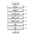
- FIG. 1 is a flowchart illustrating an example of a method for manufacturing a turbine blade according to the first embodiment.
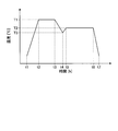
- FIG. 2 is a graph showing an example of a change over time in heating temperature when brazing and solution treatment are continuously performed.
- FIG. 3 is a flowchart illustrating an example of a method for manufacturing a turbine blade according to the second embodiment.
- FIG. 4 is a graph showing an example of the time change of the heating temperature in the brazing process.
- FIG. 5 is a flowchart showing an example of a turbine blade manufacturing method according to a modification.
- FIG. 6 is a flowchart illustrating an example of a turbine blade manufacturing method according to a modification.
- FIG. 1 is a flowchart illustrating an example of a method for manufacturing a turbine blade according to the first embodiment.
- FIG. 2 is a graph showing an example of a change over time in heating temperature when brazing and solution treatment are continuously performed.
- FIG. 3 is a flowchart illustrating an example of a method for
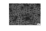
- FIG. 7 is a view showing a micrograph showing the precipitation state of the ⁇ ′ phase with respect to the base material of the turbine blade according to Comparative Example 1.
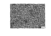
- FIG. 8 is a view showing a micrograph showing the precipitation state of the ⁇ ′ phase with respect to the base material of the turbine blade according to Comparative Example 2.
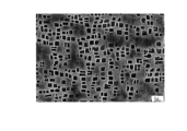
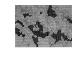
- FIG. 9 is a view showing a micrograph showing the precipitation state of the ⁇ ′ phase in the base material of the turbine blade according to the example.
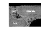
- FIG. 10 is a view showing a micrograph showing the brazed portion of the base material of the turbine blade according to Comparative Example 2 and the vicinity thereof.
- FIG. 11 is an enlarged micrograph showing a brazed portion of the base material of the turbine blade according to Comparative Example 2.
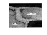
- FIG. 12 is a view showing a micrograph showing the brazed portion of the base material of the turbine blade according to the example and the vicinity thereof.
- FIG. 1 is a flowchart illustrating an example of a method for manufacturing a turbine blade according to the first embodiment.
- the turbine blade manufacturing method according to the first embodiment includes a step of forming a turbine blade base material such as a stationary blade or a moving blade of a gas turbine (step S ⁇ b> 10), and a base material A process of performing a hydrostatic pressure treatment (step S20), a process of forming a wear-resistant coat (first coat) on the surface of the base material (step S30), and an oxidation-resistant coat ( A step of forming a second coat) (step S40), a step of performing brazing treatment and solution treatment on the base material (step S50), and a step of performing aging treatment on the base material (step S60).
- a base material constituting a turbine blade such as a stationary blade or a moving blade is formed.
- a turbine blade for example, a moving blade with a shroud or the like can be cited.
- a plurality of shrouded rotor blades are arranged side by side in a predetermined direction, for example, the rotational direction of the rotor of the turbine, and have a contact surface.
- the base material which comprises a turbine blade is formed using materials, such as an alloy excellent in heat resistance, for example, Ni base alloy.
- the Ni-based alloy include Cr: 12.0% to 14.3%, Co: 8.5% to 11.0%, Mo: 1.0% to 3.5%, W: 3. 5% or more and 6.2% or less, Ta: 3.0% or more and 5.5% or less, Al: 3.5% or more and 4.5% or less, Ti: 2.0% or more and 3.2% or less, C: Examples include a Ni-based alloy having a composition of 0.04% or more and 0.12% or less, B: 0.005% or more and 0.05% or less, with the balance being Ni and inevitable impurities.
- the Ni-based alloy having the above composition may contain Zr: 0.001 ppm or more and 5 ppm or less.
- the Ni-based alloy having the above composition may contain Mg and / or Ca: 1 ppm or more and 100 ppm or less, Pt: 0.02% or more and 0.5% or less, Rh: 0.02% or more, and 0.0.
- One or two or more of 5% or less and Re: 0.02% or more and 0.5% or less may be contained, or both of them may be contained.
- the base material is formed by casting or forging using the above materials.
- a base material such as a conventional casting (CC), a unidirectional solidification (DS), and a single crystal (SC) can be formed.
- CC conventional casting
- DS unidirectional solidification
- SC single crystal
- the base material may be a unidirectionally solidified material or a single crystal material.
- the hot isostatic pressing (HIP) in step S20 is performed at a temperature of, for example, 1180 ° C. or higher and 1220 ° C. or lower, with the base material placed in an argon gas atmosphere. Thereby, it heats in the state in which the pressure was equally applied with respect to the whole surface of a base material. After the hot isostatic pressure treatment is completed, the temperature of the base material is lowered by stopping heating (slow cooling). In addition, you may perform the process similar to the solution treatment mentioned later after step S20.
- a wear-resistant coat (first coat) is formed on a portion of the base material corresponding to, for example, the contact surface 3 of the rotor blade 1 shown in FIG.
- a cobalt-based wear resistant material such as Trivalloy (registered trademark) 800 can be used as the wear resistant coat.
- the layer of the material can be formed on the base material corresponding to the contact surface 3 by a technique such as atmospheric pressure plasma spraying, high-speed flame spraying, low-pressure plasma spraying, or atmospheric plasma spraying.
- an oxidation resistant coat (second coat) is formed on the surface of the base material.
- the material for the oxidation resistant coating for example, an alloy material such as MCrAlY having higher oxidation resistance than the base material can be used.
- the above-mentioned alloy material or the like is sprayed onto the surface of the base material to form an oxidation resistant coat.
- a brazing process is performed on the base material, and after a slow cooling, a solution treatment is performed.
- the brazing process is a process in which the brazing material is melted and joined to the base material by heating the brazing material in the base material.
- the brazing material for example, a material such as Amdry (registered trademark) DF-6A is used.
- the liquidus temperature of the brazing material is, for example, about 1155 ° C.
- the amount of brazing material used for the brazing process is adjusted in advance by performing an experiment or the like.
- the heat treatment can be performed at a first temperature (T1) at which the brazing material can be melted, for example, a temperature of 1175 ° C. or higher and 1215 ° C. or lower.
- the solution treatment is a process in which the ⁇ ′ phase, which is an intermetallic compound, is dissolved and grown in the base material by heating the base material.
- the heat treatment can be performed at a second temperature (T2) lower than the heating temperature in the brazing treatment, for example, a temperature of 1100 ° C. or higher and 1140 ° C. or lower.
- FIG. 2 is a graph showing an example of the temporal change of the heating temperature in the heat treatment in step S50.
- the horizontal axis indicates time
- the vertical axis indicates temperature.
- a brazing process is first performed.
- a brazing material is placed in a base material, and the brazing material is put into a predetermined heating furnace, and a heater of the heating furnace is operated to start heating (time t1).
- the furnace temperature (heating temperature) of the heating furnace reaches the first temperature T1 (time t2)
- the temperature rise in the furnace is stopped and heat treatment is performed at the first temperature T1 for a predetermined time.
- the brazing material is melted and joined to the base material.
- the furnace temperature may be raised to a predetermined preheating temperature, and a heat treatment (preheat treatment) at the preheating temperature may be performed for a predetermined time.
- the preheating temperature is set to a temperature lower than the liquidus temperature of the brazing material, and can be set to 1100 ° C., for example.
- the temperature of the base material is reduced at a rate of about 3 ° C./min to 20 ° C./min.
- the temperature is lowered to a third temperature T3 lower than the second temperature T2 (slow cooling).
- the cooling rate may be adjusted by supplying a cooling gas into the heating furnace.
- 3rd temperature T3 it can be set as the temperature of 980 degreeC or more and 1020 degrees C or less, for example.
- step S50 is completed by taking out the base material from the heating furnace.
- step S50 diffuses the surface of the wear-resistant coating and the oxidation-resistant coating base material, and improves the adhesion between the surface of the base material and each coat.
- the aging treatment in step S60 by heating the base material subjected to the solution treatment, the ⁇ ′ phase grown by the solution treatment is further grown in the base material, and the ⁇ ′ phase generated by the solution treatment is also produced. A ⁇ ′ phase having a smaller diameter is precipitated. This small-diameter ⁇ ′ phase increases the strength of the base material. Therefore, the aging treatment finally adjusts the strength and ductility of the base material by precipitating a small-diameter ⁇ ′ phase and increasing the strength of the base material.
- the temperature can be set to 830 ° C. or higher and 870 ° C. or lower.
- the heater of the heating furnace is stopped, and the temperature of the base material is rapidly reduced at a temperature reduction rate of about 30 ° C./min, for example, by supplying a cooling gas into the heating furnace. (Rapid cooling).
- the base material is cooled by slow cooling and then the solution treatment is performed. This can be suppressed. Thereby, the quality improvement of a brazing part can be aimed at. Moreover, since the brazing blade manufacturing method according to the present embodiment continuously performs the brazing treatment and the solution treatment, it is possible to shorten the heat treatment time and simplify the process.
- FIG. 3 is a flowchart showing an example of a diffusion process in the method for manufacturing a turbine blade according to the second embodiment.
- the order of brazing processing is different from that of the first embodiment.
- the method for manufacturing a turbine blade includes a step of forming a base material of the turbine blade (step S110) and a step of performing a hot isostatic pressure process on the base material (step S120). ), A step of brazing the base material (step S130), a step of forming a wear-resistant coat (first coat) on the surface of the base material (step S140), and a surface of the base material and the wear-resistant coat It includes a step of forming an oxidation resistant coat (second coat) (Step S150), a step of performing a solution treatment on the base material (Step S160), and a step of performing an aging treatment on the base material (Step S170). Since step S110 and step S120 are the same as step S10 and step S20 in the first embodiment, description thereof will be omitted.
- FIG. 4 is a graph showing an example of a change over time in the heating temperature in the heat treatment in step S130.
- the horizontal axis of FIG. 4 indicates time, and the vertical axis indicates temperature.
- processing similar to the brazing processing and slow cooling in the first embodiment is performed (from time t1 to t3). By cooling with gradual cooling, generation of voids or the like in the brazed portion is suppressed.
- a third temperature T3 for example, a temperature of 980 ° C. or more and 1020 ° C. or less
- the temperature of the base material is set to, for example, 30 ° C. by supplying a cooling gas into the heating furnace.
- the temperature is rapidly decreased (rapid cooling) at a temperature decrease rate of about min.
- rapid cooling By performing the rapid cooling, the cooling process is performed in a short time.
- time t8 After the furnace temperature reaches a predetermined temperature (time t8), the base material is taken out from the heating furnace, thereby completing step S130.
- Steps S140 and S150 perform the same processing as Steps S30 and S40 in the first embodiment.
- step S160 the base material after the oxidation resistant coating is formed is put into a predetermined heating furnace, and a solution treatment is performed at the second temperature T2 (for example, a temperature of 1100 ° C. or higher and 1140 ° C. or lower) as in the first embodiment. I do.
- the second temperature T2 for example, a temperature of 1100 ° C. or higher and 1140 ° C. or lower
- the heater of the heating furnace is stopped, and the temperature of the base material is rapidly reduced at a temperature reduction rate of about 30 ° C./min, for example, by supplying a cooling gas into the heating furnace (rapid cooling). .
- Step S170 performs the same processing as step S60 in the first embodiment.
- the base material is cooled by slow cooling and then the solution treatment is performed. This can be suppressed. Thereby, the quality improvement of a brazing part can be aimed at.
- the slow cooling after reaching a predetermined temperature (for example, the third temperature T3), the cooling process is performed in a short time by cooling with rapid cooling.
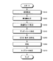
- FIG. 5 is a flowchart showing an example of a turbine blade manufacturing method according to a modification.
- the turbine blade manufacturing method according to the modification includes a step of forming a base material using a normal cast material (step S ⁇ b> 210) and a step of performing a hot isostatic pressure process on the base material (Ste S220), a step of forming a wear-resistant coat on the surface of the base material (Step S230), a step of forming an undercoat on the surface of the base material and the wear-resistant coat (Step S240), and a brazing process on the base material And a step of performing a solution treatment (step S250), a step of performing an aging treatment on the base material (step S260), and a step of forming a top coat on the base material (step S270).
- Steps S210 to S230 are the same as steps S10 and S20 in the first embodiment, and thus description thereof is omitted.
- an undercoat is formed on the surface of the base material.
- the undercoat is a part of a thermal barrier coating (TBC) for protecting the turbine blade from high temperature.
- TBC thermal barrier coating
- the undercoat prevents the base material from being oxidized and improves the adhesion of the topcoat.
- an alloy material such as MCrAlY having higher oxidation resistance than the base material can be used.
- the undercoat is formed by spraying the alloy material or the like on the surface of the base material.
- the surface of the base material Before forming the undercoat on the surface of the base material, the surface of the base material may be roughened by spraying alumina (Al 2 O 3 ) on the surface of the base material, for example. Thereby, the adhesion between the base material and the undercoat is improved by the anchor effect. Note that a cleaning process for cleaning the surface of the base material may be performed after the blasting process.
- alumina Al 2 O 3
- Steps S250 and S260 perform the same processing as Steps S250 and S260 in the first embodiment.
- the undercoat is diffused on the roughened surface of the base material, and the adhesion between the surface of the base material and the undercoat is improved.
- a top coat is formed on the surface of the undercoat.
- the top coat is a part of the thermal barrier coating and protects the surface of the base material from high temperature.
- a material having a low thermal conductivity such as ceramic is used.
- the ceramic for example, a material mainly containing zirconia is used.
- the above material is formed by atmospheric plasma spraying on the surface of the undercoat.
- the turbine blade manufacturing method performs brazing, solution treatment, and aging treatment before forming the top coat on the base material, it is possible to suppress the occurrence of spots or cracks in the top coat. As a result, it is possible to improve the quality of the brazed portion while suppressing the occurrence of spots and cracks in the thermal barrier coating.
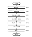
- FIG. 6 is a flowchart illustrating a turbine blade manufacturing method according to a modification.
- the manufacturing method of the turbine blade according to the modified example is the same as the example shown in FIG. 5 from step S210 to step S230, but after step S230, brazing processing and solution treatment are performed ( Step S250A) differs from the example shown in FIG. 5 in that an undercoat is formed after brazing and solution treatment (step S240A).
- a topcoat is formed without performing heat treatment (step S270A).
- an aging treatment is performed as in the example shown in FIG. 5 (step S260A).
- a plurality of base materials for turbine blades were cast using the Ni-based alloy having the composition described in the above embodiment.
- the plurality of base materials were formed as ordinary cast materials (CC materials).
- CC materials ordinary cast materials
- a material obtained by continuously performing brazing and solution treatment with the temperature change shown in FIG. 2 in the first embodiment was used as an example.
- the first temperature T1 was 1195 ° C.
- the second temperature T2 was 1120 ° C.
- the third temperature T3 was 1000 ° C.
- the aging treatment was performed at 850 ° C.
- the one subjected to the hot isostatic pressure treatment (and solution treatment), the brazing treatment, the solution treatment and the aging treatment was designated as Comparative Example 2.
- the brazing treatment was performed at 1195 ° C.
- the solution treatment was performed at 1120 ° C.
- the aging treatment was performed at 850 ° C. Further, after the brazing treatment, solution treatment and aging treatment, each was cooled by rapid cooling.
- FIG. 7 is a photomicrograph showing the precipitation state of the ⁇ ′ phase for the base material of the turbine blade according to Comparative Example 1.
- FIG. 8 is a photomicrograph showing the precipitation state of the ⁇ ′ phase with respect to the base material of the turbine blade according to Comparative Example 2.
- FIG. 9 is a micrograph showing the precipitation state of the ⁇ ′ phase in the base material of the turbine blade according to the example.
- the ⁇ ′ phase grown by the solution treatment and the small-diameter ⁇ ′ phase precipitated by the aging treatment exist in a well-balanced manner.
- the diameter of the ⁇ ′ phase grown in the solution treatment is smaller than that of the base material according to Comparative Example 1, It is in a state where sufficient ductility cannot be secured.
- the ⁇ ′ phase precipitates and grows during cooling of the brazing process.
- Comparative Example 2 since the brazing treatment is cooled rapidly, the ⁇ ′ phase does not grow sufficiently and the diameter is small.
- the brazing treatment by cooling the base material by slow cooling, it is possible to improve the quality of the brazed portion, and also by precipitation after the brazing treatment.
- the ⁇ ′ phase grown by the solution treatment and the small-diameter ⁇ ′ phase precipitated by the aging treatment are contained in a well-balanced manner.
- FIG. 10 is a photomicrograph showing the brazed portion of the base material of the turbine blade according to Comparative Example 2 and the vicinity thereof.
- FIG. 11 is a photomicrograph showing an enlarged view of the brazed portion of the base material of the turbine blade according to Comparative Example 2.
- FIG. 12 is a photomicrograph showing the brazed portion of the base material of the turbine blade according to the example and the vicinity thereof.
- the brazed portion of the base material of the turbine blade according to Comparative Example 2 is formed with many voids.
- the void is hardly seen in the brazed portion of the base material of the turbine blade according to the example.
- the quality of the brazed portion can be improved.
Landscapes
- Chemical & Material Sciences (AREA)
- Engineering & Computer Science (AREA)
- Mechanical Engineering (AREA)
- Materials Engineering (AREA)
- Metallurgy (AREA)
- Organic Chemistry (AREA)
- Physics & Mathematics (AREA)
- Plasma & Fusion (AREA)
- Chemical Kinetics & Catalysis (AREA)
- General Engineering & Computer Science (AREA)
- Thermal Sciences (AREA)
- Crystallography & Structural Chemistry (AREA)
- Combustion & Propulsion (AREA)
- Turbine Rotor Nozzle Sealing (AREA)
- Coating By Spraying Or Casting (AREA)
Priority Applications (4)
| Application Number | Priority Date | Filing Date | Title |
|---|---|---|---|
| DE112017005096.0T DE112017005096T5 (de) | 2016-10-07 | 2017-10-05 | Verfahren zur Herstellung einer Turbinenschaufel |
| CN201780044092.5A CN109715334B (zh) | 2016-10-07 | 2017-10-05 | 涡轮叶片的制造方法 |
| KR1020197002969A KR102152601B1 (ko) | 2016-10-07 | 2017-10-05 | 터빈 블레이드의 제조 방법 |
| US16/321,276 US20190168327A1 (en) | 2016-10-07 | 2017-10-05 | Method for producing turbine blade |
Applications Claiming Priority (2)
| Application Number | Priority Date | Filing Date | Title |
|---|---|---|---|
| JP2016198776A JP6746458B2 (ja) | 2016-10-07 | 2016-10-07 | タービン翼の製造方法 |
| JP2016-198776 | 2016-10-07 |
Publications (1)
| Publication Number | Publication Date |
|---|---|
| WO2018066644A1 true WO2018066644A1 (ja) | 2018-04-12 |
Family
ID=61831702
Family Applications (1)
| Application Number | Title | Priority Date | Filing Date |
|---|---|---|---|
| PCT/JP2017/036267 WO2018066644A1 (ja) | 2016-10-07 | 2017-10-05 | タービン翼の製造方法 |
Country Status (6)
Families Citing this family (7)
| Publication number | Priority date | Publication date | Assignee | Title |
|---|---|---|---|---|
| JP6746457B2 (ja) * | 2016-10-07 | 2020-08-26 | 三菱日立パワーシステムズ株式会社 | タービン翼の製造方法 |
| JP7398198B2 (ja) * | 2019-03-12 | 2023-12-14 | 三菱重工業株式会社 | タービン動翼及びコンタクト面製造方法 |
| CN111496339A (zh) * | 2020-06-03 | 2020-08-07 | 郑州机械研究所有限公司 | 蜂窝板制备方法及蜂窝板钎焊用夹具 |
| KR102278835B1 (ko) * | 2021-04-12 | 2021-07-19 | 주식회사 성일터빈 | 브레이징을 이용한 가스터빈 베인의 코어플러그 제조방법 |
| US11865622B2 (en) * | 2021-08-30 | 2024-01-09 | General Electric Company | Oxidation and wear resistant brazed coating |
| CN116638222A (zh) * | 2023-06-20 | 2023-08-25 | 北京航空航天大学 | 一种含锆钎料及其制备方法和应用 |
| CN117230392B (zh) * | 2023-11-09 | 2024-01-16 | 北京航空航天大学宁波创新研究院 | 一种Al-Mg-Si系铝合金与Al-Zn-Mg系铝合金的兼容热处理强化方法 |
Citations (8)
| Publication number | Priority date | Publication date | Assignee | Title |
|---|---|---|---|---|
| JP2002103031A (ja) * | 2000-09-29 | 2002-04-09 | Mitsubishi Heavy Ind Ltd | ろう付け方法 |
| JP2003034853A (ja) * | 2001-07-24 | 2003-02-07 | Mitsubishi Heavy Ind Ltd | Ni基合金の熱処理方法 |
| JP2003049253A (ja) * | 2001-05-14 | 2003-02-21 | Alstom (Switzerland) Ltd | ニッケルベース超合金製の単結晶製品中の亀裂又は隙間を接合又は修復する方法 |
| JP2006299378A (ja) * | 2005-04-25 | 2006-11-02 | National Institute For Materials Science | 熱処理装置と蒸着処理装置の複合装置 |
| JP2006299410A (ja) * | 2005-03-25 | 2006-11-02 | Osaka Prefecture | Ni3Si−Ni3Ti−Ni3Nb系複相金属間化合物,その製造方法,高温構造材料 |
| JP2012000739A (ja) * | 2010-06-21 | 2012-01-05 | Mitsubishi Heavy Ind Ltd | ろう付補修方法及びガスタービン高温部品 |
| JP2014055543A (ja) * | 2012-09-12 | 2014-03-27 | Toshiba Corp | トランジションピースの損傷補修方法およびトランジションピース |
| WO2014136235A1 (ja) * | 2013-03-07 | 2014-09-12 | 株式会社日立製作所 | 基材上へのアルミナイド皮膜の形成方法 |
Family Cites Families (14)
| Publication number | Priority date | Publication date | Assignee | Title |
|---|---|---|---|---|
| JPH04220167A (ja) * | 1990-12-19 | 1992-08-11 | Kanto Yakin Kogyo Kk | アルミニウムあるいはアルミニウム合金部材のろう付 け方法 |
| DE69800263T2 (de) * | 1997-01-23 | 2001-02-08 | Mitsubishi Heavy Industries, Ltd. | Nickelbasis Legierung aus stengelförmigen Kristallen mit guter Hochtemperaturbeständigkeit gegen interkristalline Korrosion, Verfahren zur Herstellung der Legierung, grosses Werkstück, sowie Verfahren zur Herstellung eines grossen Werkstückes aus dieser Legierung |
| US20100126014A1 (en) | 2008-11-26 | 2010-05-27 | General Electric Company | Repair method for tbc coated turbine components |
| CN101439430B (zh) * | 2008-12-30 | 2010-12-01 | 沈阳黎明航空发动机(集团)有限责任公司 | 一种钎焊方法 |
| JP2011214541A (ja) | 2010-04-01 | 2011-10-27 | Toshiba Ge Turbine Service Kk | タービン翼の補修方法および補修されたタービン翼 |
| CN102120292B (zh) * | 2011-03-18 | 2012-07-25 | 中国航空工业集团公司北京航空制造工程研究所 | 一种高温合金薄壁件裂纹真空钎焊修复方法 |
| JP2013068085A (ja) | 2011-09-20 | 2013-04-18 | Toshiba Corp | スキーラ付きガスタービン動翼の補修方法 |
| JP2013194694A (ja) | 2012-03-22 | 2013-09-30 | Toshiba Corp | ガスタービン動翼の補修方法およびガスタービン動翼 |
| JP5967534B2 (ja) * | 2012-08-17 | 2016-08-10 | 東北電力株式会社 | 熱遮蔽被膜の形成方法および熱遮蔽被膜被覆部材 |
| CN103111784B (zh) * | 2013-02-16 | 2015-06-03 | 大连宏海新能源发展有限公司 | 斯特林机加热头部件的钎焊定位装置及真空钎焊工艺 |
| US20150004362A1 (en) * | 2013-07-01 | 2015-01-01 | General Electric Company | Multilayered coatings with diamond-like carbon |
| CN204283884U (zh) * | 2014-11-18 | 2015-04-22 | 上海日立电器有限公司 | 一种用于转子压缩机的叶片 |
| CN104526287B (zh) * | 2015-01-12 | 2016-11-16 | 南昌航空大学 | 一种气动扳轴修复再制造方法 |
| ES2698523T3 (es) * | 2015-03-17 | 2019-02-05 | MTU Aero Engines AG | Procedimiento para producir un elemento de construcción a partir de un material compuesto con una matriz metálica y fases intermetálicas incorporadas |
-
2016
- 2016-10-07 JP JP2016198776A patent/JP6746458B2/ja active Active
-
2017
- 2017-10-05 CN CN201780044092.5A patent/CN109715334B/zh active Active
- 2017-10-05 KR KR1020197002969A patent/KR102152601B1/ko active Active
- 2017-10-05 US US16/321,276 patent/US20190168327A1/en not_active Abandoned
- 2017-10-05 WO PCT/JP2017/036267 patent/WO2018066644A1/ja active Application Filing
- 2017-10-05 DE DE112017005096.0T patent/DE112017005096T5/de active Pending
Patent Citations (8)
| Publication number | Priority date | Publication date | Assignee | Title |
|---|---|---|---|---|
| JP2002103031A (ja) * | 2000-09-29 | 2002-04-09 | Mitsubishi Heavy Ind Ltd | ろう付け方法 |
| JP2003049253A (ja) * | 2001-05-14 | 2003-02-21 | Alstom (Switzerland) Ltd | ニッケルベース超合金製の単結晶製品中の亀裂又は隙間を接合又は修復する方法 |
| JP2003034853A (ja) * | 2001-07-24 | 2003-02-07 | Mitsubishi Heavy Ind Ltd | Ni基合金の熱処理方法 |
| JP2006299410A (ja) * | 2005-03-25 | 2006-11-02 | Osaka Prefecture | Ni3Si−Ni3Ti−Ni3Nb系複相金属間化合物,その製造方法,高温構造材料 |
| JP2006299378A (ja) * | 2005-04-25 | 2006-11-02 | National Institute For Materials Science | 熱処理装置と蒸着処理装置の複合装置 |
| JP2012000739A (ja) * | 2010-06-21 | 2012-01-05 | Mitsubishi Heavy Ind Ltd | ろう付補修方法及びガスタービン高温部品 |
| JP2014055543A (ja) * | 2012-09-12 | 2014-03-27 | Toshiba Corp | トランジションピースの損傷補修方法およびトランジションピース |
| WO2014136235A1 (ja) * | 2013-03-07 | 2014-09-12 | 株式会社日立製作所 | 基材上へのアルミナイド皮膜の形成方法 |
Also Published As
| Publication number | Publication date |
|---|---|
| KR102152601B1 (ko) | 2020-09-08 |
| JP6746458B2 (ja) | 2020-08-26 |
| US20190168327A1 (en) | 2019-06-06 |
| CN109715334A (zh) | 2019-05-03 |
| JP2018059471A (ja) | 2018-04-12 |
| KR20190027371A (ko) | 2019-03-14 |
| CN109715334B (zh) | 2021-12-28 |
| DE112017005096T5 (de) | 2019-08-01 |
Similar Documents
| Publication | Publication Date | Title |
|---|---|---|
| WO2018066644A1 (ja) | タービン翼の製造方法 | |
| US8235275B1 (en) | Braze foil for high-temperature brazing and methods for repairing or producing components using a braze foil | |
| US8881965B2 (en) | Braze alloy for high-temperature brazing and methods for repairing or producing components using a braze alloy | |
| US7182581B2 (en) | Layer system | |
| CN101294251B (zh) | 燃气轮机叶片及其制造方法 | |
| JP2006062080A (ja) | 金属部品のクラック修繕方法および修繕された金属部品 | |
| US20100043929A1 (en) | Single crystal component and a method of heat treating a single crystal component | |
| US20100000976A1 (en) | Process for Repairing a Component Comprising a Directional Microstructure by Setting a Temperature Gradient During the Laser Heat Action, and a Component Produced by Such a Process | |
| WO2015122953A2 (en) | Use of spark plasma sintering for manufacturing superalloy compound components | |
| CN109477431B (zh) | 涡轮叶片的制造方法 | |
| JP2006144061A (ja) | 遮熱コーティング部材およびその形成方法 | |
| CN109415977B (zh) | 涡轮叶片的制造方法 | |
| JP4841931B2 (ja) | 耐熱金属材料の耐酸化性の改善方法および耐熱金属部材の製造方法 | |
| CN108779517A (zh) | 高抗氧化合金和使用所述合金的燃气涡轮机应用 | |
| CN1726297B (zh) | 从合金制备有改善的可焊性和/或机械加工性的部件的方法 | |
| JP2006016671A (ja) | Ni基合金部材とその製造法及びタービンエンジン部品並びに溶接材料とその製造法 | |
| JP2018091333A (ja) | 垂直亀裂遮熱コーティングを形成する方法および垂直亀裂遮熱コーティングを含む物品 | |
| KR101382141B1 (ko) | 고온 계면 안정성이 우수한 코팅층을 갖는 니켈기 합금 및 그 제조방법 | |
| JP2012157880A (ja) | 耐溶損性鋳物および金属溶湯接触部材 | |
| US20110171394A1 (en) | Method of making a combustion turbine component using thermally sprayed transient liquid phase forming layer | |
| KR101980177B1 (ko) | 합금분말을 이용한 단결정 초내열합금의 천이액상접합방법 | |
| CN116875930A (zh) | 铜合金/镍基合金梯度材料增材制造方法 | |
| JP2012157881A (ja) | 耐溶損性鋳物、その製造方法および金属溶湯接触部材 |
Legal Events
| Date | Code | Title | Description |
|---|---|---|---|
| 121 | Ep: the epo has been informed by wipo that ep was designated in this application |
Ref document number: 17858480 Country of ref document: EP Kind code of ref document: A1 |
|
| ENP | Entry into the national phase |
Ref document number: 20197002969 Country of ref document: KR Kind code of ref document: A |
|
| 122 | Ep: pct application non-entry in european phase |
Ref document number: 17858480 Country of ref document: EP Kind code of ref document: A1 |