WO2018066566A1 - ブラシレスモータの制御装置及び制御方法 - Google Patents
ブラシレスモータの制御装置及び制御方法 Download PDFInfo
- Publication number
- WO2018066566A1 WO2018066566A1 PCT/JP2017/036005 JP2017036005W WO2018066566A1 WO 2018066566 A1 WO2018066566 A1 WO 2018066566A1 JP 2017036005 W JP2017036005 W JP 2017036005W WO 2018066566 A1 WO2018066566 A1 WO 2018066566A1
- Authority
- WO
- WIPO (PCT)
- Prior art keywords
- brushless motor
- command value
- voltage
- rotational speed
- time
- Prior art date
- Legal status (The legal status is an assumption and is not a legal conclusion. Google has not performed a legal analysis and makes no representation as to the accuracy of the status listed.)
- Ceased
Links
Images



Classifications
-
- H—ELECTRICITY
- H02—GENERATION; CONVERSION OR DISTRIBUTION OF ELECTRIC POWER
- H02P—CONTROL OR REGULATION OF ELECTRIC MOTORS, ELECTRIC GENERATORS OR DYNAMO-ELECTRIC CONVERTERS; CONTROLLING TRANSFORMERS, REACTORS OR CHOKE COILS
- H02P6/00—Arrangements for controlling synchronous motors or other dynamo-electric motors using electronic commutation dependent on the rotor position; Electronic commutators therefor
- H02P6/08—Arrangements for controlling the speed or torque of a single motor
-
- G—PHYSICS
- G01—MEASURING; TESTING
- G01R—MEASURING ELECTRIC VARIABLES; MEASURING MAGNETIC VARIABLES
- G01R19/00—Arrangements for measuring currents or voltages or for indicating presence or sign thereof
- G01R19/165—Indicating that current or voltage is either above or below a predetermined value or within or outside a predetermined range of values
- G01R19/16533—Indicating that current or voltage is either above or below a predetermined value or within or outside a predetermined range of values characterised by the application
- G01R19/16538—Indicating that current or voltage is either above or below a predetermined value or within or outside a predetermined range of values characterised by the application in AC or DC supplies
- G01R19/16547—Indicating that current or voltage is either above or below a predetermined value or within or outside a predetermined range of values characterised by the application in AC or DC supplies voltage or current in AC supplies
-
- H—ELECTRICITY
- H02—GENERATION; CONVERSION OR DISTRIBUTION OF ELECTRIC POWER
- H02P—CONTROL OR REGULATION OF ELECTRIC MOTORS, ELECTRIC GENERATORS OR DYNAMO-ELECTRIC CONVERTERS; CONTROLLING TRANSFORMERS, REACTORS OR CHOKE COILS
- H02P23/00—Arrangements or methods for the control of AC motors characterised by a control method other than vector control
- H02P23/0004—Control strategies in general, e.g. linear type, e.g. P, PI, PID, using robust control
- H02P23/0027—Control strategies in general, e.g. linear type, e.g. P, PI, PID, using robust control using different modes of control depending on a parameter, e.g. the speed
-
- H—ELECTRICITY
- H02—GENERATION; CONVERSION OR DISTRIBUTION OF ELECTRIC POWER
- H02P—CONTROL OR REGULATION OF ELECTRIC MOTORS, ELECTRIC GENERATORS OR DYNAMO-ELECTRIC CONVERTERS; CONTROLLING TRANSFORMERS, REACTORS OR CHOKE COILS
- H02P27/00—Arrangements or methods for the control of AC motors characterised by the kind of supply voltage
- H02P27/04—Arrangements or methods for the control of AC motors characterised by the kind of supply voltage using variable-frequency supply voltage, e.g. inverter or converter supply voltage
- H02P27/06—Arrangements or methods for the control of AC motors characterised by the kind of supply voltage using variable-frequency supply voltage, e.g. inverter or converter supply voltage using DC to AC converters or inverters
- H02P27/08—Arrangements or methods for the control of AC motors characterised by the kind of supply voltage using variable-frequency supply voltage, e.g. inverter or converter supply voltage using DC to AC converters or inverters with pulse width modulation
- H02P27/085—Arrangements or methods for the control of AC motors characterised by the kind of supply voltage using variable-frequency supply voltage, e.g. inverter or converter supply voltage using DC to AC converters or inverters with pulse width modulation wherein the PWM mode is adapted on the running conditions of the motor, e.g. the switching frequency
-
- H—ELECTRICITY
- H02—GENERATION; CONVERSION OR DISTRIBUTION OF ELECTRIC POWER
- H02P—CONTROL OR REGULATION OF ELECTRIC MOTORS, ELECTRIC GENERATORS OR DYNAMO-ELECTRIC CONVERTERS; CONTROLLING TRANSFORMERS, REACTORS OR CHOKE COILS
- H02P29/00—Arrangements for regulating or controlling electric motors, appropriate for both AC and DC motors
- H02P29/60—Controlling or determining the temperature of the motor or of the drive
- H02P29/66—Controlling or determining the temperature of the rotor
-
- H—ELECTRICITY
- H02—GENERATION; CONVERSION OR DISTRIBUTION OF ELECTRIC POWER
- H02P—CONTROL OR REGULATION OF ELECTRIC MOTORS, ELECTRIC GENERATORS OR DYNAMO-ELECTRIC CONVERTERS; CONTROLLING TRANSFORMERS, REACTORS OR CHOKE COILS
- H02P6/00—Arrangements for controlling synchronous motors or other dynamo-electric motors using electronic commutation dependent on the rotor position; Electronic commutators therefor
- H02P6/14—Electronic commutators
- H02P6/16—Circuit arrangements for detecting position
- H02P6/18—Circuit arrangements for detecting position without separate position detecting elements
- H02P6/182—Circuit arrangements for detecting position without separate position detecting elements using back-emf in windings
-
- H—ELECTRICITY
- H02—GENERATION; CONVERSION OR DISTRIBUTION OF ELECTRIC POWER
- H02P—CONTROL OR REGULATION OF ELECTRIC MOTORS, ELECTRIC GENERATORS OR DYNAMO-ELECTRIC CONVERTERS; CONTROLLING TRANSFORMERS, REACTORS OR CHOKE COILS
- H02P6/00—Arrangements for controlling synchronous motors or other dynamo-electric motors using electronic commutation dependent on the rotor position; Electronic commutators therefor
- H02P6/28—Arrangements for controlling current
-
- H—ELECTRICITY
- H02—GENERATION; CONVERSION OR DISTRIBUTION OF ELECTRIC POWER
- H02P—CONTROL OR REGULATION OF ELECTRIC MOTORS, ELECTRIC GENERATORS OR DYNAMO-ELECTRIC CONVERTERS; CONTROLLING TRANSFORMERS, REACTORS OR CHOKE COILS
- H02P23/00—Arrangements or methods for the control of AC motors characterised by a control method other than vector control
- H02P23/14—Estimation or adaptation of motor parameters, e.g. rotor time constant, flux, speed, current or voltage
-
- H—ELECTRICITY
- H02—GENERATION; CONVERSION OR DISTRIBUTION OF ELECTRIC POWER
- H02P—CONTROL OR REGULATION OF ELECTRIC MOTORS, ELECTRIC GENERATORS OR DYNAMO-ELECTRIC CONVERTERS; CONTROLLING TRANSFORMERS, REACTORS OR CHOKE COILS
- H02P25/00—Arrangements or methods for the control of AC motors characterised by the kind of AC motor or by structural details
- H02P25/02—Arrangements or methods for the control of AC motors characterised by the kind of AC motor or by structural details characterised by the kind of motor
- H02P25/022—Synchronous motors
- H02P25/024—Synchronous motors controlled by supply frequency
- H02P25/026—Synchronous motors controlled by supply frequency thereby detecting the rotor position
-
- H—ELECTRICITY
- H02—GENERATION; CONVERSION OR DISTRIBUTION OF ELECTRIC POWER
- H02P—CONTROL OR REGULATION OF ELECTRIC MOTORS, ELECTRIC GENERATORS OR DYNAMO-ELECTRIC CONVERTERS; CONTROLLING TRANSFORMERS, REACTORS OR CHOKE COILS
- H02P25/00—Arrangements or methods for the control of AC motors characterised by the kind of AC motor or by structural details
- H02P25/02—Arrangements or methods for the control of AC motors characterised by the kind of AC motor or by structural details characterised by the kind of motor
- H02P25/022—Synchronous motors
- H02P25/03—Synchronous motors with brushless excitation
Definitions
- the present invention switches a plurality of energization modes for selecting a phase to be energized by pulse width modulation operation among a plurality of phases of a brushless motor by comparing an induced voltage of a non-energized phase with a threshold value to thereby rotate the rotational speed of the brushless motor.
- the present invention relates to a control device and control method to control.
- Patent Document 1 discloses two phases to be energized among a three-phase synchronous motor, an inverter connected to the three-phase synchronous motor, and a plurality of switching elements, and a three-phase winding of the three-phase synchronous motor. And a controller that selects and controls energization of the inverter by pulse width modulation operation in six energization modes, and detects the terminal potential of the non-energized phase (induced voltage, transformer electromotive force) and reference A drive system of a synchronous motor is disclosed, which sequentially switches the conduction mode according to a comparison result with a voltage.
- a brushless motor which is a drive source of an electric water pump for circulating cooling water of an internal combustion engine
- sensorless control that switches the energization mode based on the induced voltage of the non-energized phase If the load increases rapidly due to foreign matter mixing into the pump section while the speed is extremely low (for example, about 100 rpm to 200 rpm), the motor may stop without feedback control in time for the reduction in motor rotation speed. .
- the motor rotational speed is calculated from the switching cycle of the energization mode
- the motor stops with the latest value of the measurement data of the motor rotational speed exceeds the command value and the switching of the energization mode is interrupted
- the measurement data is In order to maintain the state higher than the command value without being updated, the input voltage of the motor is controlled to decrease, and the motor may continue to stop.
- the present invention has been made in view of the above problems, and it is an object of the present invention to provide a control device and control method of a brushless motor capable of preventing the motor from continuing to stop even if the load rapidly increases in an extremely low rotation range. Do.
- the control device for a brushless motor includes the steps of measuring the time when the induced voltage does not change or the time when the energization mode does not switch, and when the measurement time reaches a predetermined time. Increasing the input voltage of the
- the input voltage is increased to start the motor, so that the measurement data of the rotational speed is temporarily higher than the command value. Even if the motor stops, the motor can be prevented from continuing to stop.
- FIG. 1 is a circuit diagram showing configurations of a motor control device and a brushless motor according to an embodiment of the present invention. It is a functional block diagram of a control unit in an embodiment of the present invention. It is a flowchart which shows the implementation procedure of a rising process of the applied voltage in embodiment of this invention. It is a flowchart which shows the procedure of the process which raises applied voltage by correction
- FIG. 1 shows a cooling system of an internal combustion engine for a vehicle including an electric water pump driven by a brushless motor as an example of a control device and a control method of a brushless motor according to the present invention.
- a transmission 20 such as CVT (Continuously Variable Transmission), which is an example of a power transmission device, is connected to an output shaft of the internal combustion engine 10, and the output of the transmission 20 is transmitted to driving wheels of the vehicle (not shown).
- the cooling system of the internal combustion engine 10 is a water cooling type cooling device for circulating cooling water in the circulation passage, and the electric water pump 40 with the flow control valve 30 and the brushless motor 45 as drive sources, the radiator 50 and cylinder head side cooling
- the water passage 61, the cylinder block side cooling water passage 62, the heater core 91, the oil warmer & cooler 21 of the transmission 20, a piping group 70 connecting these, and the like are included.
- the cylinder head side cooling water passage 61 of the internal combustion engine 10 includes a cooling water inlet 13 provided at one end of the cylinder head 11 in the cylinder arrangement direction and a cooling water outlet 14 provided at the other end of the cylinder head 11 in the cylinder arrangement direction. It is connected and extended in the cylinder head 11. Further, the cylinder block side cooling water passage 62 of the internal combustion engine 10 branches from the cylinder head side cooling water passage 61 to reach the cylinder block 12 and extends into the cylinder block 12 and is provided in the cylinder block 12. It is a cooling water passage connected to 15.
- first cooling water pipe 71 is connected to the cooling water outlet 14 of the cylinder head 11, and the other end of the first cooling water pipe 71 is connected to the cooling water inlet 51 of the radiator 50.
- second cooling water pipe 72 is connected to the cooling water outlet 15 of the cylinder block side cooling water passage 62, and the other end of the second cooling water pipe 72 is connected to the four inlet ports 31 of the flow control valve 30. It is connected to the first inlet port 31 of -34.
- one end of the third cooling water pipe 73 is connected to the middle of the first cooling water pipe 71, and the other end is connected to the second inlet port 32 of the flow control valve 30.
- the oil warmer & cooler 21 is provided to adjust the temperature of the hydraulic fluid of the transmission 20.
- one end of the fourth cooling water pipe 74 is connected to the first cooling water pipe 71 between the cooling water outlet 14 and the connection point of the third cooling water pipe 73, and the other end is the third of the flow control valve 30. It is connected to the inlet port 33.
- the fourth cooling water pipe 74 is provided with various heat exchange devices such as a heater core 91 for warming the conditioned air in the vehicle air conditioner.
- the flow control valve 30 has one outlet port 35, one end of a sixth cooling water pipe 76 is connected to the outlet port 35, and the other end of the sixth cooling water pipe 76 is connected to the electric water pump 40. It is connected to the suction port 41.
- One end of a seventh cooling water pipe 77 is connected to the discharge port 42 of the electric water pump 40, and the other end of the seventh cooling water pipe 77 is connected to the cooling water inlet 13 of the cylinder head 11. Further, one end of the eighth cooling water pipe 78 is connected to the first cooling water pipe 71 on the downstream side of the portion to which the third cooling water pipe 73 and the fourth cooling water pipe 74 are connected, and the other end is the sixth It is connected to the cooling water pipe 76.
- Flow control valve 30 has four inlet ports 31-34 and one outlet port 35 as described above, and cooling water pipes 72, 73, 74, 75 are connected to inlet ports 31-34, respectively. .
- the flow rate control valve 30 circulates the cooling water pipes 72, 73, 74, 75 by controlling the opening areas of the cooling water pipes 72, 73, 74, 75, that is, the outlet areas of the cooling water circulation lines. Adjust the amount of cooling water. Even if all the inlet ports 31 to 34 of the flow control valve 30 are closed, the cooling water passing through the cylinder head side cooling water passage 61 can be circulated by bypassing the radiator 50 by the eighth cooling water pipe 78 It is configured as follows.
- the above-described electric water pump 40 and the flow control valve 30 are controlled by the control device 100.
- the control device 100 controls the discharge flow rate of the electric water pump 40 (in other words, the rotational speed of the brushless motor 45) and the flow rate control based on the coolant temperature of the internal combustion engine 10 detected by the water temperature sensors 81 and 82, and the like.
- the opening area of the inlet port 31-34 of the valve 30 is controlled.
- the water temperature sensor 82 of the water temperature sensors 81 and 82 can be omitted, and the present invention is not limited to the configuration provided with two water temperature sensors.
- the control device 100 controls the flow control valve 30 so that all the inlet ports 31 to 34 are closed, for example, at the cold machine start-up time when the coolant temperature of the internal combustion engine 10 is lower than the cold machine determination threshold. Is controlled to an extremely low rotation speed (eg, about 100 rpm to about 200 rpm). That is, at the time of cold start of the internal combustion engine 10, the cooling water which has flowed into the cylinder head side cooling water passage 61 is circulated without passing through other heat exchange devices including the radiator 50, and the circulating amount of the cooling water is minimized. Limited. Thus, the temperature rise of the cylinder head 11 is promoted, and the occurrence of temperature variation in the cooling water circulation path is suppressed. Thereafter, the control device 100 opens the inlet ports 31 to 34 as the temperature of the coolant in the internal combustion engine 10 rises, and increases the rotational speed of the electric water pump 40 to keep the temperature of the coolant within the appropriate temperature range. To be done.
- an extremely low rotation speed eg, about 100 rpm to about
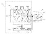
- FIG. 2 is a circuit diagram showing one aspect of a control unit of the brushless motor 45 which is a drive source of the electric water pump 40 and the brushless motor 45 in the control device 100.
- the control device 100 for controlling the brushless motor 45 includes a motor drive circuit 212 and a control unit 213.
- the control unit 213 includes an A / D converter 213a, a microprocessor (CPU, MPU, etc.), etc.
- a microcomputer 213b is provided.
- the brushless motor 45 is a three-phase DC brushless motor, and comprises star-connected U-phase, V-phase and W-phase three-phase windings 215u, 215v, 215w in a cylindrical stator, not shown, which is fixed.
- a permanent magnet rotor (rotor) 216 is rotatably provided in a space formed in the center of the rotor.
- the three-phase windings 215u, 215v, 215w are star-connected in the brushless motor 45 shown in FIG. 2, a brushless motor in which the three-phase windings 215u, 215v, 215w are delta-connected can be employed. .
- the motor drive circuit 212 has an inverter circuit 212 a in which switching elements 217 a to 217 f including reverse-parallel diodes 218 a to 218 f are bridge-connected in three phases, and a power supply circuit 219.
- the switching elements 217a to 217f are formed of, for example, FETs.
- the control terminals (gate terminals) of the switching elements 217a to 217f are connected to the control unit 213, and the control unit 213 controls on / off of the switching elements 217a to 217f by pulse width modulation (PWM) of triangular wave comparison method.
- PWM pulse width modulation
- the voltage (motor input voltage) applied to the brushless motor 45 is controlled.
- the control unit 213 compares each triangular wave (carrier) with a PWM timer (PWM duty) set according to the command duty ratio (command pulse width) to thereby select each switching element 217a.
- the timing to turn on / off the signal 217 f is detected.
- the value of the PWM timer is set to a larger value as the duty ratio increases, and is set to a maximum value at 100% duty and a minimum value (zero) at 0% duty.
- the brushless motor 45 does not have a sensor that detects rotor position information, and the control unit 213 performs drive control of the brushless motor 45 by a sensorless drive method that does not use a sensor that detects rotor position information.
- the unit 213 switches the sensorless drive method between the sine wave drive method and the rectangular wave drive method according to the motor rotation speed.
- the sine wave drive method is a method of driving a brushless motor 45 by adding a sine wave voltage to each phase.
- the control unit 213 obtains positional information of the rotor from an induced voltage (speed electromotive voltage) generated by rotation of the rotor, and during a detection period of the rotor position by the speed electromotive voltage. Then, the rotor position is estimated based on the motor rotational speed, the three-phase output set value is calculated from the estimated rotor position and the PWM duty, and the direction and strength of the current are controlled by the difference between the voltages of the phases. An alternating current is applied to each phase. The control unit 213 calculates the motor rotational speed based on the detection cycle of the rotor position.
- the rectangular wave drive method is a method of driving the brushless motor 45 by sequentially switching a selected pattern (energization mode) of two phases to which a pulse voltage is applied among the three phases for each predetermined rotor position.
- the control unit 213 compares the voltage (transformer electromotive voltage) induced in the non-energized phase (open phase) with the application of the pulse voltage to the energized phase with the threshold value.
- the position information is obtained, and the switching timing of the energization mode, which is the selection pattern of the energization phase, is detected based on the position information.
- the speed electromotive voltage detected for position detection in the sine wave drive system has a lower output level as the motor rotation speed decreases, and the accuracy of position detection decreases in the low rotation range.
- the control unit 213 controls the brushless motor 45 by the sine wave drive method in the high rotation area where the position information can be detected with sufficient accuracy by the sine wave drive method, that is, the area where the motor rotation speed is higher than the set value.
- the brushless motor 45 is controlled by the rectangular wave drive method.
- the low rotation area where the position information can not be detected with sufficient accuracy by the sine wave drive method includes an area where the motor rotational speed is lower than the set value, and the time when the motor is started. Furthermore, in PWM control of the brushless motor 45, the control unit 213 determines, for example, the duty ratio of PWM control according to the deviation between the detected value of the motor rotational speed and the target motor rotational speed (rotational speed command value), Bring the actual motor rotational speed closer to the target motor rotational speed.
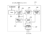
- FIG. 3 is a functional block diagram of the control unit 213 that performs sensorless control of the rectangular wave drive system.
- the control unit 213 includes a PWM generation unit 251, a gate signal switching unit 252, an energization mode determination unit 253, a comparison unit 254, a voltage threshold switching unit 255, a voltage threshold learning unit 256, and a non-energized phase voltage selection unit 257.
- the PWM generation unit 251 generates a PWM wave that is pulse width modulated by the triangular wave comparison method based on the applied voltage command (command voltage) corresponding to the deviation between the rotation speed command value and the rotation speed detection value.
- the conduction mode determination unit 253 is a device that outputs a mode command signal for determining the conduction mode in the motor drive circuit 212, and switches the conduction mode to six ways using the mode switching trigger signal output by the comparison unit 254 as a trigger.
- the energization mode indicates a selection pattern of two phases to which a pulse voltage is applied among the three phases of U phase, V phase and W phase of the brushless motor 45.
- a first conduction mode M1 for flowing current from the U phase to the V phase a second conduction mode M2 for flowing current from the U phase to the W phase, a second for flowing current from the V phase to the W phase 3) Conduction mode M3; Fourth conduction mode M4 to flow current from V phase to U phase; Fifth conduction mode M5 to flow current from W phase to U phase; flow current from W phase to V phase
- Six energization modes of the sixth energization mode M6 are set. Then, the conduction mode determining unit 253 outputs a mode command signal for instructing any one of the first to sixth conduction modes M1 to M6 according to the mode switching trigger signal output from the comparison unit 254.
- Gate signal switching unit 252 determines what kind of operation each switching element 217 a to 217 f of motor drive circuit 212 switches based on a mode command signal which is an output of energization mode determination unit 253, and according to the determination Six gate pulse signals are output to the motor drive circuit 212.
- Voltage threshold switching unit 255 sequentially switches and outputs a threshold to be compared with the induced voltage according to each conduction mode in detection control of switching timing of the conduction mode based on the induced voltage of the non-energized phase, and switches the threshold switching timing It is determined based on a mode command signal which is an output of the energization mode determination unit 253.
- the non-energized phase voltage selection unit 257 selects the detection value of the voltage of the non-energized phase from the three-phase terminal voltages Vu, Vv, Vw of the brushless motor 45 according to the mode command signal. It is a circuit which outputs to 256. Although the terminal voltage of the non-energized phase is strictly the voltage between the ground GND and the terminal, the voltage at the neutral point is detected in this embodiment, and the voltage between the neutral point and the ground GND and the terminal is detected. The difference between the voltage and the voltage is determined to obtain terminal voltages Vu, Vv and Vw.
- the comparing unit 254 compares the threshold output by the voltage threshold switching unit 255 with the voltage detection value (detection value of the induced voltage) of the non-energized phase output by the non-energized phase voltage selection unit 257.
- a switching timing in other words, it is detected whether or not a predetermined rotor position (magnetic pole position) for switching the conduction mode has been detected, and a mode switching trigger is output to the conduction mode determining unit 253 when the switching timing is detected.
- the voltage threshold learning unit 256 is a functional unit that updates and stores the threshold used to determine the switching timing of the energization mode.
- the voltage threshold learning unit 256 detects an induced voltage at a predetermined magnetic pole position that switches the conduction mode, and performs threshold learning processing to correct the threshold stored in the voltage threshold switching unit 255 based on the detection result. Do.
- the energization modes consist of six energization modes M1 to M6, and the control unit 213 sequentially switches these energization modes M1 to M6 at switching angle positions set at intervals of an electrical angle of 60 degrees.
- the brushless motor 45 is rotationally driven by sequentially switching two phases to which a pulse voltage (pulsed voltage) is applied among the three phases.
- the control unit 213 sets the third position when the angular position (magnetic pole position) of the rotor is 30 deg.
- the switching from the conduction mode M3 to the fourth conduction mode M4 is performed, and the switching from the fourth conduction mode M4 to the fifth conduction mode M5 is performed when the rotor angular position is 90 degrees, and the rotor angular position is 150 degrees.
- the sixth conduction mode M6 is switched to the first conduction mode M1, and the rotor angular position is Switching is performed from the first conduction mode M1 to the second conduction mode M2 when the angle is 270 deg, and from the second conduction mode M2 to the third conduction mode when the rotor angular position is 330 deg. To switch to de M3.
- the voltage threshold value switching unit 255 of the control unit 213 stores the induced voltage (transformer electromotive force) of the non-energized phase at the angular position of the rotor at which the energization mode is switched as a threshold.
- a threshold value corresponding to the current conduction mode at that time is output.
- the comparison unit 254 outputs a signal indicating that the angle for performing switching to the next conduction mode is detected when the induced voltage of the non-energized phase reaches the threshold value, and the conduction mode determination unit 253 determines based on the signal. Execute switching of energization mode.
- the control unit 213 turns on the switching element 217a (upper arm of U phase) of the U phase upper stage, for example, in the first conduction mode M1 in which current flows from U phase to V phase.
- the ON / OFF ratio of V phase lower stage switching element 217 d (V phase lower arm) while controlling, average applied voltage of U phase and V phase to flow current is variably controlled by PWM duty Do.
- the control unit 213 controls, for example, the switching elements 217 other than the switching element 217a in the upper U-phase and the switching element 217d in the V-phase lower in the first conduction mode M1 to be off. be able to.
- the control unit 213 (gate signal switching unit 252) performs PWM control of the inverter circuit 212a by a complementary control method of driving the upper arm of the conducting phase with the PWM wave of the reverse phase to the PWM wave that drives the lower arm of the conducting phase. can do.
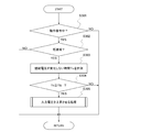
- step S301 the control unit 213 determines whether the rotation operation command state or stop command state of the brushless motor 45 is in effect.
- control unit 213 ends the present routine as it is for the stop command state and continues the stop operation state as it is, and proceeds to step S302 when it is the rotation operation command state.
- the control unit 213 determines whether the PWM control of the brushless motor 45 is performed by the rectangular wave drive method, in other words, the command value of the rotational speed of the brushless motor 45 adopts the rectangular wave drive method. It is determined whether or not it is within the low rotational speed range.
- the control unit 213 ends the present routine as it is and continues the drive control of the brushless motor 45 in the sine wave drive system.
- step S303 the control unit 213 measures the time during which the induced voltage of the non-energized phase does not change or the time during which the energization mode is not switched.
- the time during which the induced voltage of the non-energized phase does not change is the continuation time of the state in which the difference between the previous value and the current value of the detected value of the induced voltage of the non-energized phase sampled at predetermined intervals That is, the time during which the energization mode is not switched is an elapsed time from the previous switching of the energization mode.
- PWM control is performed on the brushless motor 45 by the rectangular wave drive method, if the load is rapidly increased due to foreign matter biting into the pump portion of the electric water pump 40, increase control of the applied voltage (input voltage) against rotation decrease However, the brushless motor 45 may stop in some cases (due to the response delay of the rotation feedback control).
- the switching timing of the energization mode which is the update timing of the rotational speed measurement value is not detected, and the rotational speed measurement value updated immediately before the stop is maintained as it is.
- the rotational speed measurement value is higher than the rotational speed command value, in the rotational speed feedback control by the control unit 213, the rotational speed of the brushless motor 45 is set even though the rotational speed measurement value is not updated.
- the applied voltage (rotational torque) of the brushless motor 45 is lowered, and the brushless motor 45 stopped by the rapid increase of the load continues to be stopped.
- the control unit 213 is required to increase the rotational torque in order to realize the rotational speed command value.
- the brushless motor 45 is maintained in the stopped state by the operation of reducing the rotational torque.
- the induced voltage of the non-energized phase does not change, and if the induced voltage does not change, the switching timing of the energization mode is not detected and the switching of the energization mode is not performed.
- the control unit 213 measures time in step S303 in order to determine whether the motor is in the stopped state due to the rapid increase of the load as described above and the brushless motor 45 continues to be stopped. Next, the control unit 213 proceeds to step S304, and determines whether the time measured in step S303 has reached a predetermined time (threshold) TSL.
- the predetermined time TSL is previously adapted as a value capable of detecting as soon as possible the state in which the brushless motor 45 continues to stop from the time when the induced voltage of the non-energized phase does not change or the time when the energization mode is not switched. It is done. Then, if the time measured in step S303 has not reached the predetermined time TSL, the control unit 213 determines that the brushless motor 45 is not in the state of continuing to stop, and terminates the present routine.
- the PWM control in the rectangular wave drive system which determines the applied voltage according to the difference between the measured value of the rotational speed and the rotational speed command is continued.
- step S303 determines that the brushless motor 45 continues to stop and proceeds to step S305.
- step S305 the control unit 213 corrects the setting process of the applied voltage based on the difference between the measured value of the rotational speed of the brushless motor 45 and the rotational speed command to obtain the voltage (input voltage) applied to the brushless motor 45. Raise it.
- the control unit 213 corrects the normal setting process to raise and change the voltage (input voltage) applied to the brushless motor 45 (applied voltage more than the normal setting process) To restart the brushless motor 45 stopped by the increase of the load.
- the control unit 213 can perform a process of temporarily increasing and correcting the rotational speed command value (target rotational speed) used for the rotational speed feedback control.
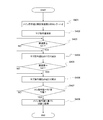
- the flowchart of FIG. 5 shows an aspect of the process of increasing and correcting the rotational speed command value as the process of increasing the applied voltage in step S305.
- step S401 the control unit 213 sets the higher one of the measured value of the rotational speed held without updating the value before the stop by the motor rotation stop and the rotational speed command value as the reference rotational speed. Select as NB.
- step S402 the control unit 213 proceeds to step S402, and temporarily adds the predetermined additional correction component NHOS to the reference rotational speed NB set in step S401 to temporarily increase the applied voltage and restart the motor. Set as the sub command value used for.
- the control unit 213 sets the sub-command value to a rotational speed higher than the reference rotational speed NB, the sub-command value is set to a rotational speed higher than the measured value at which updating is stopped.
- the applied voltage is increased by bringing the measured value close to the sub command value (in other words, in order to increase the motor rotational speed).
- the control unit 213 can generate a rotational torque that resists the rapidly increased load to restart the brushless motor 45 (allowing removal of trapped foreign matter), and the electric water pump 40 It can be suppressed that it is kept in the stopped state. Therefore, when the control unit 213 controls the electrically driven water pump 40 to an extremely low rotational speed, the electrically driven water pump may be operated even if the load rapidly increases due to the inclusion of foreign matter or the like and the electrically driven water pump 40 is stopped. 40 can be restarted immediately to continue cooling water circulation.
- the control unit 213 controls the internal combustion engine based on the detection result by the water temperature sensor 81, 82.
- the state of progress of warm-up 10 was accurately detected, and the control of the circulation path of the cooling water and the control of the discharge amount of the electric water pump 40 were appropriately performed, whereby foreign matter was mixed in the electric water pump 40 It is possible to suppress a decrease in the drivability of the internal combustion engine 10 at that time.
- control unit 213 can set the sub command value to a speed higher by a predetermined rotation speed than the main command value, as described above, the higher one of the measurement value of the rotation speed and the rotation speed command value Assuming that the reference rotational speed NB is a sub-command value that is higher than the reference rotational speed NB by a predetermined rotational speed, a sub-command value higher than the measurement value and not too high can be stably set.
- step S403 After the control unit 213 executes processing for increasing and correcting the rotational speed command value used for rotational speed feedback control in step S402, the process proceeds to step S403, and the rotational speed of the restarted brushless motor 45 is lower than the sub command value. It is determined whether or not the speed has increased to a first rotation speed N1 higher than the main command value. Then, the control unit 213 repeats the determination in step S403 until the rotational speed of the brushless motor 45 reaches the first rotational speed N1, thereby maintaining the sub command value as the initial value and the rotational speed of the brushless motor 45 When the first rotation speed N1 is reached, the process proceeds to step S404.
- step S404 the control unit 213 executes processing for setting the rotational speed reduced by the first decrease correction amount ⁇ N1 from the previous value of the sub command value as a new sub command value to gradually reduce the sub command value, To be used for rotational speed feedback control.
- step S405 the control unit 213 determines whether or not the sub command value subjected to the gradual reduction process has dropped to a second rotation speed N2 lower than the first rotation speed N1 and higher than the main command value. Determine.
- step S404 the control unit 213 returns to step S404, and continues the sub command value every predetermined time until the sub command value decreases to the second rotation speed N2.
- the process of decreasing by 1 decrease correction amount ⁇ N1 is repeated.
- step S405 the control unit 213 determines in step S405 that the sub command value has decreased to the second rotation speed N2
- step S406 reduces the previous value of the sub command value by the second decrease correction amount ⁇ N2.
- the processing of setting the rotational speed as a new sub command value is performed to gradually reduce the sub command value.
- the second decrease correction amount ⁇ N2 is set to a value the absolute value of which is smaller than the first decrease correction amount ⁇ N1, whereby the sub command value is reduced to the second rotation speed N2, the sub command value The reduction speed of the sub command value is slower than that of the second rotation speed N2.
- the control unit 213 proceeds to step S407, determines whether the sub command value has decreased to the main command value, and the sub command value is lower than the main command value. While it is high, the process returns to step S406, and the process of decreasing the sub command value by the second decrease correction amount ⁇ N2 is repeated at predetermined time intervals.
- control unit 213 gradually reduces the sub command value to the main command value, but carries out processing to switch the decrease speed of the sub command value to a slower speed on the way. Then, when the sub command value decreases to the main command value, the control unit 213 proceeds to step S408, cancels the control based on the sub command value, and returns to the control based on the main command value.
- the motor rotation speed approaches the initial value of the sub command value, and the motor rotation speed approaches the first rotation speed N1 (main command value while compensating for the movement of the brushless motor 45).
- N1 main command value while compensating for the movement of the brushless motor 45.
- the control unit 213 performs switching of the reduction speed of the sub command value only once to make the reduction speed gradually slower, but switches the reduction speed twice or more. be able to.
- the time chart of FIG. 6 exemplifies a change in rotational speed command value when the process shown in the flowchart of FIG. 5 is performed.
- the control unit 213 increases the rotational speed command value stepwise from the main command value. Perform the process.
- the brushless motor 45 is re-driven to update the rotational speed measurement value, and when the rotational speed measurement value rises to N1 at time t2, the control unit 213 controls the rotational speed command value to increase.
- the reduction process is started to gradually reduce the rotational speed command value (sub command value).
- the control unit 213 changes the reduction speed of the rotation speed command value later than before, and when it decreases to the main command value at time t4, it is based on the main command value. Return to normal control.
- the control unit 213 can perform a process of decreasing and correcting the rotational speed measurement value used for the rotational speed feedback control.
- the flowchart of FIG. 7 shows an aspect of the process of decreasing and correcting the rotational speed measurement value as the process of increasing the applied voltage in step S305.
- the control unit 213 measures the rotational speed as the elapsed time from reaching the predetermined time TSL becomes longer as the time when the induced voltage of the non-energized phase does not change or the time when the energizing mode does not change in step S501. Correct the value lower. In other words, the correction value for decreasing the rotational speed measurement value is changed to a larger value as the elapsed time after reaching the predetermined time TSL becomes longer. Then, in the next step S502, the control unit 213 determines the duty ratio of the PWM control based on the comparison between the corrected rotational speed measurement value and the rotational speed command value.
- step S503 the control unit 213 changes the induced voltage of the non-energized phase to change the energization mode, in other words, the brushless motor 45 is restarted. Determine if it has been. Then, when the brushless motor 45 is restarted, the control unit 213 proceeds to step S504, cancels the decrease correction of the rotational speed measurement value (or gradually reduces the decrease correction amount), and keeps the measurement result of the rotational speed as it is. Return to the normal control used.
- the control unit can not stop the rotational speed feedback control in time for the rapid increase of the load and the brushless motor 45 is stopped, and the rotational speed measurement value is not updated and remains higher than the command value.
- the rotational speed measurement value used for the rotational speed feedback control (PWM control) is forcibly and gradually reduced without detection of the position information of the brushless motor 45.
- the rotational speed measurement value used for the rotational speed feedback control becomes lower than the command value as time passes from a state higher than the command value, and the rotational speed measurement value becomes lower than the command value.
- the brushless motor 45 can be restarted.
- the control unit 213 can restart the brushless motor 45 and the electric water pump 40 It is suppressed to continue the stop state.
- the control unit 213 can perform a process of increasing and correcting the applied voltage command value (input voltage command value) determined by the rotational speed feedback control.
- the flowchart of FIG. 8 illustrates an aspect of a process of increasing and correcting the application voltage command value as the process of increasing the application voltage in step S305.
- the control unit 213 applies the applied voltage as the elapsed time from reaching the predetermined time TSL increases in time in which the induced voltage of the non-energized phase does not change or the time in which the energizing mode is not switched in step S601.
- the voltage correction value (voltage correction value> 0) for increasing and correcting the command value is set to a larger value.
- the correction value of the applied voltage command value has an upper limit value set in advance, and holds the upper limit value after reaching the upper limit value as time passes.
- control unit 213 proceeds to step S602 to add the voltage correction value set in step S601 to the applied voltage command value calculated based on the deviation between the measured value of the rotational speed of brushless motor 45 and the rotational speed command.
- the increase correction is performed, and the command duty ratio is determined based on the corrected applied voltage command value. Even if the measured value of the rotational speed and the rotational speed command value (in other words, the control deviation) are held constant by the increase correction of the applied voltage command value, the voltage (input The voltage (V) increases, and the brushless motor 45 will be restarted.
- step S603 the control unit 213 changes whether the induced voltage of the non-energized phase changes and the switching timing of the energization mode is detected, in other words, the brushless motor 45 restarts from the stop state Determine if it has been. Then, when the brushless motor 45 restarts and the induced voltage of the non-energized phase starts to change and switching of the energization mode is performed, the control unit 213 proceeds to step S604 and increases the applied voltage command value. The correction is canceled (or the increase correction amount of the applied voltage command value is gradually decreased), and the applied voltage command value determined by the rotational speed feedback control is used as it is to return to the normal control that determines the command duty ratio.
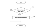
- step S701 the control unit 213 determines whether the stop of the brushless motor 45 and the restart by the process of increasing the applied voltage are repeated. For example, the control unit 213 increments the number of repetitions when step S305 is performed again within a predetermined time after stopping the process of increasing the applied voltage in step S305, and stops the process of increasing the applied voltage in step S305. After step S305 is not performed again within a predetermined time, the number of repetitions is reset to zero.
- the control unit 213 determines that the stop of the brushless motor 45 and the restart by the process of increasing the applied voltage are repeated. If the stop and restart of the brushless motor 45 are repeated at a predetermined frequency or more, the control unit 213 proceeds to step S702 to increase the lower limit value of the rotational speed command value to a speed higher than the initial value (reference value). to correct.
- the rotational speed command value used for control after canceling the process of increasing the applied voltage in step S305 is set to a value for repetition higher than the main command value.
- control unit 213 can change the lower limit value (command value for repetition time) to a higher rotational speed as the number of repetitions increases.
- the control unit 213 rotates the lower limit value instead of the rotational speed command value calculated based on the coolant temperature or the like when the rotational speed command value (main command value) calculated based on the coolant temperature or the like falls below the lower limit value. It is selected as a command value used for speed feedback control.
- the control unit 213 makes the lower limit value of the rotational speed command value higher and drives the brushless motor 45 to rotate at a higher rotational speed, so that when the load sharply increases, the response delay of the rotational speed feedback control causes the brushless motor to It is suppressed that 45 stops, so that repeated stop / restart is suppressed.
- the control unit 213 gradually increases and changes the lower limit value and then gradually decreases the lower limit value at a slower speed than at the increase change time (with a smaller step width than at the increase change time), and the excessively high rotational speed command value Can be suppressed.
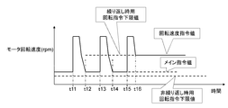
- the time chart of FIG. 10 exemplifies how the rotation command lower limit value is changed by the processing shown in the flowchart of FIG. 9.
- processing for increasing and correcting the rotation command value is performed as processing for increasing and correcting the applied voltage as the motor stops, and the motor is restarted by such processing, and the rotation command value is returned to the main command value at time t12.
- the rotation command value is increased again and corrected at time t13.
- the brushless motor 45 of the above embodiment is used as a drive source of the electric water pump 40, for example, similar operations and effects can be obtained by performing the same process on a brushless motor used as a drive source of an oil pump. It is obvious that the brushless motor 45 is not limited to the drive source of the electric water pump 40.
- the control unit 213 does not use the coolant temperature detected in the stop period and the predetermined period immediately after the restart for control, or the stop period. And the change of the cooling water temperature in the predetermined period immediately after restarting can be estimated, and cooling control can be performed based on an estimated value.
- control unit 213 can increase and correct the duty ratio command value based on the applied voltage command value, instead of increasing and correcting the applied voltage command value. That is, the control unit 213 can adopt various processes for increasing and changing the input voltage of the brushless motor 45 from the motor stop point when the time when the induced voltage does not change or the time when the energization mode does not switch reaches a predetermined time.
- the controller for a brushless motor in one aspect thereof, has a plurality of energization modes for selecting a phase to be energized by pulse width modulation operation among a plurality of phases of the brushless motor, and induces the plurality of energization modes as non-energized phases.
- the control device for controlling the rotational speed of the brushless motor by switching based on comparison of voltage and threshold value the time when the induced voltage does not change or the time when the energization mode does not change reaches a predetermined time
- a voltage control unit that raises the input voltage of the
- the voltage control unit temporarily outputs a command value of the rotational speed of the brushless motor when a time when the induced voltage does not change or a time when the energization mode does not switch reaches a predetermined time. Increase correction.
- the voltage control unit increases and corrects the higher rotational speed of the command value of the rotational speed of the brushless motor and the measurement data of the rotational speed of the brushless motor to increase the speed of the brushless motor. It is a command value used to control the rotational speed.
- the voltage control unit gradually decreases the increase correction amount of the rotational speed command value after the rotational speed of the brushless motor reaches a predetermined speed after increasing the rotational speed command value. To the command value before the increase correction. In still another preferred aspect, the voltage control unit raises the lower limit value of the command value when the increase correction of the command value of the rotational speed is repeated.
- the voltage control unit reduces and corrects measurement data of the rotational speed of the brushless motor when the time when the induced voltage does not change or the time when the energization mode does not switch reaches a predetermined time. Used to control the rotational speed.
- the voltage control unit is configured to set the input voltage of the brushless motor by controlling the rotational speed when the time when the induced voltage does not change or the time when the energization mode does not switch reaches a predetermined time. The correction voltage is added and increased.
- control method of the brushless motor has, in one aspect thereof, a plurality of energization modes for selecting a phase to be energized by pulse width modulation operation among a plurality of phases of the brushless motor, and the plurality of energization modes are non-energized phases
Landscapes
- Engineering & Computer Science (AREA)
- Power Engineering (AREA)
- Physics & Mathematics (AREA)
- General Physics & Mathematics (AREA)
- Control Of Motors That Do Not Use Commutators (AREA)
Abstract
本願発明は、ブラシレスモータの複数相のうちでパルス幅変調動作によって通電する相を選択する複数の通電モードを有し、前記複数の通電モードを非通電相の誘起電圧と閾値との比較に基づき切り替えて、前記ブラシレスモータの回転速度を制御する制御装置及び制御方法において、誘起電圧が変化しない時間又は通電モードが切り替わらない時間が所定時間に達したときにブラシレスモータの入力電圧を上昇させる。これにより、極低回転域で負荷が急増しても、ブラシレスモータが停止し続けることを抑止できる。
Description
本発明は、ブラシレスモータの複数相のうちでパルス幅変調動作によって通電する相を選択する複数の通電モードを非通電相の誘起電圧と閾値との比較により切り替えて、前記ブラシレスモータの回転速度を制御する制御装置及び制御方法に関する。
特許文献1には、三相同期電動機と、該三相同期電動機と接続し複数のスイッチング素子により構成されるインバータと、前記三相同期電動機の三相巻線のうち、通電する2つの相を選択し、6通りの通電モードにて、パルス幅変調動作によって前記インバータを通電制御する制御器と、を有し、非通電相の端子電位の検出値(誘起電圧、変圧器起電力)と基準電圧との比較結果に応じて前記通電モードを順次切り替える、同期電動機の駆動システムが開示されている。
例えば、内燃機関の冷却水を循環させる電動式ウォータポンプの駆動源であるブラシレスモータを、非通電相の誘起電圧に基づき通電モードを切り替えるセンサレス制御によって回転速度制御するシステムにおいて、回転速度の指令値が極低回転(例えば100rpm~200rpm程度)であるときにポンプ部への異物混入などによって負荷が急増すると、モータの回転速度の低下に対してフィードバック制御が間に合わずにモータが停止する場合がある。
ここで、モータ回転速度が通電モードの切り替え周期から演算される場合、モータ回転速度の計測データの最新値が指令値を上回る状態でモータが停止して通電モードの切り替えが途絶えると、計測データが更新されずに指令値よりも高い状態を保持するため、モータの入力電圧は減少制御され、モータが停止し続ける場合があった。
ここで、モータ回転速度が通電モードの切り替え周期から演算される場合、モータ回転速度の計測データの最新値が指令値を上回る状態でモータが停止して通電モードの切り替えが途絶えると、計測データが更新されずに指令値よりも高い状態を保持するため、モータの入力電圧は減少制御され、モータが停止し続ける場合があった。
本発明は上記問題点に鑑みなされたものであり、極低回転域で負荷が急増してもモータが停止し続けることを抑止できる、ブラシレスモータの制御装置及び制御方法を提供することを目的とする。
そのため、本願発明に係るブラシレスモータの制御装置は、その一態様として、誘起電圧が変化しない時間又は通電モードが切り替わらない時間が所定時間に達したときにブラシレスモータの入力電圧を上昇させる電圧制御部を備える。
また、本願発明に係るブラシレスモータの制御方法は、その一態様として、誘起電圧が変化しない時間又は通電モードが切り替わらない時間を計測するステップと、前記計測時間が所定時間に達したときにブラシレスモータの入力電圧を上昇させるステップと、を含む。
また、本願発明に係るブラシレスモータの制御方法は、その一態様として、誘起電圧が変化しない時間又は通電モードが切り替わらない時間を計測するステップと、前記計測時間が所定時間に達したときにブラシレスモータの入力電圧を上昇させるステップと、を含む。
上記発明によると、誘起電圧が変化せずに通電モードが切り替わらない状態が継続すると、入力電圧を上昇させてモータの起動を図るので、仮に回転速度の計測データが指令値よりも高い状態でモータが停止しても、モータがそのまま停止し続けることを抑止できる。
以下に本発明の実施の形態を説明する。
図1は、本発明に係るブラシレスモータの制御装置及び制御方法の一例として、ブラシレスモータで駆動される電動式ウォータポンプを含む車両用内燃機関の冷却システムを示す。
図1は、本発明に係るブラシレスモータの制御装置及び制御方法の一例として、ブラシレスモータで駆動される電動式ウォータポンプを含む車両用内燃機関の冷却システムを示す。
内燃機関10の出力軸には動力伝達装置の一例としてのCVT(Continuously Variable Transmission)などの変速機20が接続され、変速機20の出力が図示省略した車両の駆動輪に伝達される。
内燃機関10の冷却システムは、冷却水を循環通路内に循環させる水冷式冷却装置であり、流量制御弁30、ブラシレスモータ45を駆動源とする電動式ウォータポンプ40、ラジエータ50、シリンダヘッド側冷却水通路61、シリンダブロック側冷却水通路62、ヒータコア91、変速機20のオイルウォーマー&クーラー21、これらを接続する配管群70などを含んで構成される。
内燃機関10の冷却システムは、冷却水を循環通路内に循環させる水冷式冷却装置であり、流量制御弁30、ブラシレスモータ45を駆動源とする電動式ウォータポンプ40、ラジエータ50、シリンダヘッド側冷却水通路61、シリンダブロック側冷却水通路62、ヒータコア91、変速機20のオイルウォーマー&クーラー21、これらを接続する配管群70などを含んで構成される。
内燃機関10のシリンダヘッド側冷却水通路61は、シリンダヘッド11の気筒配列方向の一方端に設けた冷却水入口13とシリンダヘッド11の気筒配列方向の他方端に設けた冷却水出口14とを接続してシリンダヘッド11内に延設される。
また、内燃機関10のシリンダブロック側冷却水通路62は、シリンダヘッド側冷却水通路61から分岐してシリンダブロック12に至り、シリンダブロック12内に延設されてシリンダブロック12に設けた冷却水出口15に接続される冷却水通路である。
また、内燃機関10のシリンダブロック側冷却水通路62は、シリンダヘッド側冷却水通路61から分岐してシリンダブロック12に至り、シリンダブロック12内に延設されてシリンダブロック12に設けた冷却水出口15に接続される冷却水通路である。
シリンダヘッド11の冷却水出口14には、第1冷却水配管71の一端が接続され、第1冷却水配管71の他端は、ラジエータ50の冷却水入口51に接続される。
一方、シリンダブロック側冷却水通路62の冷却水出口15には、第2冷却水配管72の一端が接続され、第2冷却水配管72の他端は、流量制御弁30の4つの入口ポート31-34のうちの第1入口ポート31に接続される。
一方、シリンダブロック側冷却水通路62の冷却水出口15には、第2冷却水配管72の一端が接続され、第2冷却水配管72の他端は、流量制御弁30の4つの入口ポート31-34のうちの第1入口ポート31に接続される。
また、第3冷却水配管73は、一端が第1冷却水配管71の途中に接続され、他端が流量制御弁30の第2入口ポート32に接続され、この第3冷却水配管73の途中には、変速機20の作動油の温度を調整するオイルウォーマー&クーラー21が設けられる。
更に、第4冷却水配管74は、一端が冷却水出口14と第3冷却水配管73の接続点との間の第1冷却水配管71に接続され、他端が流量制御弁30の第3入口ポート33に接続される。この第4冷却水配管74には、車両空調装置において空調空気を暖めるヒータコア91などの各種の熱交換デバイスが設けられる。
更に、第4冷却水配管74は、一端が冷却水出口14と第3冷却水配管73の接続点との間の第1冷却水配管71に接続され、他端が流量制御弁30の第3入口ポート33に接続される。この第4冷却水配管74には、車両空調装置において空調空気を暖めるヒータコア91などの各種の熱交換デバイスが設けられる。
第5冷却水配管75は、一端がラジエータ50の冷却水出口52に接続され、他端が流量制御弁30の第4入口ポート34に接続される。
流量制御弁30は、1つの出口ポート35を有し、この出口ポート35には第6冷却水配管76の一端が接続され、第6冷却水配管76の他端は、電動式ウォータポンプ40の吸込口41に接続される。
流量制御弁30は、1つの出口ポート35を有し、この出口ポート35には第6冷却水配管76の一端が接続され、第6冷却水配管76の他端は、電動式ウォータポンプ40の吸込口41に接続される。
そして、電動式ウォータポンプ40の吐出口42には第7冷却水配管77の一端が接続され、第7冷却水配管77の他端はシリンダヘッド11の冷却水入口13に接続される。
また、第8冷却水配管78の一端は、第3冷却水配管73、第4冷却水配管74が接続される部分よりも下流側の第1冷却水配管71に接続され、他端は第6冷却水配管76に接続される。
また、第8冷却水配管78の一端は、第3冷却水配管73、第4冷却水配管74が接続される部分よりも下流側の第1冷却水配管71に接続され、他端は第6冷却水配管76に接続される。
流量制御弁30は、前述したように4つの入口ポート31-34と1つの出口ポート35とを有し、入口ポート31-34には冷却水配管72,73,74,75がそれぞれ接続される。そして、流量制御弁30は、各冷却水配管72,73,74,75の開口面積、つまり、各冷却水循環ラインの出口面積を制御することで、冷却水配管72,73,74,75を循環する冷却水量を調整する。
なお、流量制御弁30の入口ポート31-34が全て閉じられても、シリンダヘッド側冷却水通路61を経由した冷却水を第8冷却水配管78によってラジエータ50をバイパスさせて循環させることができるよう構成されている。
なお、流量制御弁30の入口ポート31-34が全て閉じられても、シリンダヘッド側冷却水通路61を経由した冷却水を第8冷却水配管78によってラジエータ50をバイパスさせて循環させることができるよう構成されている。
上記の電動式ウォータポンプ40及び流量制御弁30は、制御装置100によって制御される。
制御装置100は、水温センサ81,82で検出される内燃機関10の冷却水温度などに基づき、電動式ウォータポンプ40の吐出流量(換言すれば、ブラシレスモータ45の回転速度)、及び、流量制御弁30の入口ポート31-34の開口面積を制御する。なお、例えば、水温センサ81,82のうちの水温センサ82を省略することができ、水温センサを2つ備える構成に限定されるものではない。
制御装置100は、水温センサ81,82で検出される内燃機関10の冷却水温度などに基づき、電動式ウォータポンプ40の吐出流量(換言すれば、ブラシレスモータ45の回転速度)、及び、流量制御弁30の入口ポート31-34の開口面積を制御する。なお、例えば、水温センサ81,82のうちの水温センサ82を省略することができ、水温センサを2つ備える構成に限定されるものではない。
制御装置100は、例えば、内燃機関10の冷却水温度が冷機判定閾値よりも低い冷機始動時に、入口ポート31-34が全て閉じるように流量制御弁30を制御し、また、電動式ウォータポンプ40の回転速度を極低回転速度(例えば100rpm~200rpm程度)に制御する。
つまり、内燃機関10の冷機始動時には、シリンダヘッド側冷却水通路61に流入した冷却水は、ラジエータ50を含む他の熱交換デバイスを経由することなく循環され、かつ、冷却水の循環量が最小限に抑制される。これにより、シリンダヘッド11の温度上昇が促進され、かつ、冷却水循環経路内で温度のばらつきが生じることが抑制される。
その後、制御装置100は、内燃機関10の冷却水温度の上昇に伴って入口ポート31-34を開口させるとともに電動式ウォータポンプ40の回転速度を増加させ、冷却水温度が適正温度範囲内に保持されるようにする。
つまり、内燃機関10の冷機始動時には、シリンダヘッド側冷却水通路61に流入した冷却水は、ラジエータ50を含む他の熱交換デバイスを経由することなく循環され、かつ、冷却水の循環量が最小限に抑制される。これにより、シリンダヘッド11の温度上昇が促進され、かつ、冷却水循環経路内で温度のばらつきが生じることが抑制される。
その後、制御装置100は、内燃機関10の冷却水温度の上昇に伴って入口ポート31-34を開口させるとともに電動式ウォータポンプ40の回転速度を増加させ、冷却水温度が適正温度範囲内に保持されるようにする。
図2は、電動式ウォータポンプ40の駆動源であるブラシレスモータ45、及び、制御装置100におけるブラシレスモータ45の制御部の一態様を示す回路図である。
ブラシレスモータ45を制御する制御装置100は、モータ駆動回路212と制御ユニット213とを備え、制御ユニット213は、A/D変換器213aやマイクロプロセッサ(CPU,MPUなど)などを含んで構成されるマイクロコンピュータ213bを備える。
ブラシレスモータ45を制御する制御装置100は、モータ駆動回路212と制御ユニット213とを備え、制御ユニット213は、A/D変換器213aやマイクロプロセッサ(CPU,MPUなど)などを含んで構成されるマイクロコンピュータ213bを備える。
ブラシレスモータ45は、3相DCブラシレスモータであり、スター結線されるU相、V相及びW相の3相巻線215u、215v、215wを、図示省略した円筒状の固定子に備え、該固定子の中央部に形成した空間に永久磁石回転子(ロータ)216を回転可能に備える。
なお、図2に示したブラシレスモータ45は、3相巻線215u、215v、215wがスター結線されるが、3相巻線215u、215v、215wがデルタ結線されるブラシレスモータを採用することができる。
モータ駆動回路212は、逆並列のダイオード218a~218fを含んでなるスイッチング素子217a~217fを3相ブリッジ接続したインバータ回路212aと、電源回路219とを有する。スイッチング素子217a~217fは例えばFETで構成される。
なお、図2に示したブラシレスモータ45は、3相巻線215u、215v、215wがスター結線されるが、3相巻線215u、215v、215wがデルタ結線されるブラシレスモータを採用することができる。
モータ駆動回路212は、逆並列のダイオード218a~218fを含んでなるスイッチング素子217a~217fを3相ブリッジ接続したインバータ回路212aと、電源回路219とを有する。スイッチング素子217a~217fは例えばFETで構成される。
スイッチング素子217a~217fの制御端子(ゲート端子)は、制御ユニット213に接続され、制御ユニット213は、スイッチング素子217a~217fのオン、オフを三角波比較方式のパルス幅変調(PWM)によって制御してブラシレスモータ45に印加する電圧(モータ入力電圧)を制御する。
三角波比較方式のPWM制御において、制御ユニット213は、三角波(キャリア)と、指令デューティ比(指令パルス幅)に応じて設定されるPWMタイマ(PWMデューティ)とを比較することで、各スイッチング素子217a~217fをオン/オフさせるタイミングを検出する。
三角波比較方式のPWM制御において、制御ユニット213は、三角波(キャリア)と、指令デューティ比(指令パルス幅)に応じて設定されるPWMタイマ(PWMデューティ)とを比較することで、各スイッチング素子217a~217fをオン/オフさせるタイミングを検出する。
なお、PWMタイマの値は、デューティ比が大きいほど大きな値に設定され、デューティ100%では最大値、デューティ0%では最小値(零)に設定される。
ブラシレスモータ45は回転子の位置情報を検出するセンサを備えず、制御ユニット213は、ブラシレスモータ45の駆動制御を回転子の位置情報を検出するセンサを用いないセンサレス駆動方式によって行い、更に、制御ユニット213は、センサレスでの駆動方式をモータ回転速度に応じて正弦波駆動方式と矩形波駆動方式とに切り替える。
ブラシレスモータ45は回転子の位置情報を検出するセンサを備えず、制御ユニット213は、ブラシレスモータ45の駆動制御を回転子の位置情報を検出するセンサを用いないセンサレス駆動方式によって行い、更に、制御ユニット213は、センサレスでの駆動方式をモータ回転速度に応じて正弦波駆動方式と矩形波駆動方式とに切り替える。
正弦波駆動方式は、各相に正弦波電圧を加えてブラシレスモータ45を駆動する方式である。
この正弦波駆動方式では、制御ユニット213は、回転子が回転することによって発生する誘起電圧(速度起電圧)から回転子の位置情報を得る一方、速度起電圧による回転子位置の検出周期の間で、モータ回転速度に基づき回転子位置を推定し、推定した回転子位置とPWMデューティとから3相出力設定値を算出し、相間電圧の差で電流の向きと強さとを制御して3相交流電流を各相に流す。
なお、制御ユニット213は、モータ回転速度を回転子位置の検出周期に基づき算出する。
この正弦波駆動方式では、制御ユニット213は、回転子が回転することによって発生する誘起電圧(速度起電圧)から回転子の位置情報を得る一方、速度起電圧による回転子位置の検出周期の間で、モータ回転速度に基づき回転子位置を推定し、推定した回転子位置とPWMデューティとから3相出力設定値を算出し、相間電圧の差で電流の向きと強さとを制御して3相交流電流を各相に流す。
なお、制御ユニット213は、モータ回転速度を回転子位置の検出周期に基づき算出する。
また、矩形波駆動方式は、3相のうちでパルス電圧を印加する2相の選択パターン(通電モード)を所定の回転子位置毎に順次切り替えることでブラシレスモータ45を駆動する方式である。
この矩形波駆動方式では、制御ユニット213は、通電相に対するパルス状の電圧印加によって非通電相(開放相)に誘起される電圧(変圧器起電圧)と閾値とを比較することで回転子の位置情報を得て、係る位置情報に基づき通電相の選択パターンである通電モードの切り替えタイミングを検出する。
この矩形波駆動方式では、制御ユニット213は、通電相に対するパルス状の電圧印加によって非通電相(開放相)に誘起される電圧(変圧器起電圧)と閾値とを比較することで回転子の位置情報を得て、係る位置情報に基づき通電相の選択パターンである通電モードの切り替えタイミングを検出する。
ここで、正弦波駆動方式において位置検出のために検出する速度起電圧は、モータ回転速度の低下に伴って出力レベルが低下し、低回転域では位置検出の精度が低下する。一方、矩形波駆動方式において位置検出のために検出する誘起電圧は、モータ停止状態を含む低回転域においても検出可能であり、低回転域でも位置検出の精度を維持できる。
そこで、制御ユニット213は、正弦波駆動方式で位置情報を十分な精度で検出できる高回転領域、つまり、設定値よりもモータ回転速度が高い領域では、正弦波駆動方式でブラシレスモータ45を制御し、正弦波駆動方式では十分な精度で位置情報を検出できない低回転領域では、矩形波駆動方式でブラシレスモータ45を制御する。
そこで、制御ユニット213は、正弦波駆動方式で位置情報を十分な精度で検出できる高回転領域、つまり、設定値よりもモータ回転速度が高い領域では、正弦波駆動方式でブラシレスモータ45を制御し、正弦波駆動方式では十分な精度で位置情報を検出できない低回転領域では、矩形波駆動方式でブラシレスモータ45を制御する。
なお、正弦波駆動方式では十分な精度で位置情報を検出できない低回転領域には、設定値よりもモータ回転速度が低い領域、及び、モータの起動時が含まれる。
更に、制御ユニット213は、ブラシレスモータ45のPWM制御において、例えば、モータ回転速度の検出値と目標モータ回転速度(回転速度指令値)との偏差に応じてPWM制御のデューティ比を決定して、実際のモータ回転速度を目標モータ回転速度に近づける。
更に、制御ユニット213は、ブラシレスモータ45のPWM制御において、例えば、モータ回転速度の検出値と目標モータ回転速度(回転速度指令値)との偏差に応じてPWM制御のデューティ比を決定して、実際のモータ回転速度を目標モータ回転速度に近づける。
以下では、制御ユニット213による矩形波駆動方式でのブラシレスモータ45の駆動制御の一態様を詳述する。
図3は、矩形波駆動方式のセンサレス制御を実施する制御ユニット213の機能ブロック図である。
制御ユニット213は、PWM発生部251、ゲート信号切替部252、通電モード決定部253、比較部254、電圧閾値切替部255、電圧閾値学習部256、非通電相電圧選択部257を備えている。
図3は、矩形波駆動方式のセンサレス制御を実施する制御ユニット213の機能ブロック図である。
制御ユニット213は、PWM発生部251、ゲート信号切替部252、通電モード決定部253、比較部254、電圧閾値切替部255、電圧閾値学習部256、非通電相電圧選択部257を備えている。
PWM発生部251は、回転速度指令値と回転速度検出値との偏差に応じた印加電圧指令(指令電圧)に基づき、三角波比較方式によってパルス幅変調されたPWM波を生成する。
通電モード決定部253は、モータ駆動回路212における通電モードを決定するモード指令信号を出力するデバイスであり、比較部254が出力するモード切替トリガ信号をトリガとして通電モードを6通りに切り替える。
通電モード決定部253は、モータ駆動回路212における通電モードを決定するモード指令信号を出力するデバイスであり、比較部254が出力するモード切替トリガ信号をトリガとして通電モードを6通りに切り替える。
通電モードとは、ブラシレスモータ45のU相、V相、W相の3相のうちでパルス電圧を印加する2相の選択パターンを示す。
通電モードとして、U相からV相に向けて電流を流す第1通電モードM1、U相からW相に向けて電流を流す第2通電モードM2、V相からW相に向けて電流を流す第3通電モードM3、V相からU相に向けて電流を流す第4通電モードM4、W相からU相に向けて電流を流す第5通電モードM5、W相からV相に向けて電流を流す第6通電モードM6の6種類の通電モードが設定される。
そして、通電モード決定部253は、比較部254が出力するモード切替トリガ信号に応じて、第1通電モードM1~第6通電モードM6のいずれか1つを指令するモード指令信号を出力する。
通電モードとして、U相からV相に向けて電流を流す第1通電モードM1、U相からW相に向けて電流を流す第2通電モードM2、V相からW相に向けて電流を流す第3通電モードM3、V相からU相に向けて電流を流す第4通電モードM4、W相からU相に向けて電流を流す第5通電モードM5、W相からV相に向けて電流を流す第6通電モードM6の6種類の通電モードが設定される。
そして、通電モード決定部253は、比較部254が出力するモード切替トリガ信号に応じて、第1通電モードM1~第6通電モードM6のいずれか1つを指令するモード指令信号を出力する。
ゲート信号切替部252は、モータ駆動回路212の各スイッチング素子217a~217fがどのような動作でスイッチングするかを、通電モード決定部253の出力であるモード指令信号に基づいて決定し、該決定に従い6つのゲートパルス信号をモータ駆動回路212に出力する。
電圧閾値切替部255は、非通電相の誘起電圧に基づく通電モードの切り替えタイミングの検出制御において、誘起電圧と比較する閾値を各通電モードに対応させて順次切り替えて出力し、閾値の切り替えタイミングは、通電モード決定部253の出力であるモード指令信号に基づき決定される。
電圧閾値切替部255は、非通電相の誘起電圧に基づく通電モードの切り替えタイミングの検出制御において、誘起電圧と比較する閾値を各通電モードに対応させて順次切り替えて出力し、閾値の切り替えタイミングは、通電モード決定部253の出力であるモード指令信号に基づき決定される。
非通電相電圧選択部257は、モード指令信号に従い、ブラシレスモータ45の3相端子電圧Vu,Vv,Vwの中から非通電相の電圧の検出値を選択し、比較部254及び電圧閾値学習部256に出力する回路である。
尚、非通電相の端子電圧は、厳密にはグランドGND-端子間の電圧であるが、本実施形態では、中性点の電圧を検出し、この中性点の電圧とグランドGND-端子間電圧との差を求めて、端子電圧Vu,Vv,Vwとする。
尚、非通電相の端子電圧は、厳密にはグランドGND-端子間の電圧であるが、本実施形態では、中性点の電圧を検出し、この中性点の電圧とグランドGND-端子間電圧との差を求めて、端子電圧Vu,Vv,Vwとする。
比較部254は、電圧閾値切替部255が出力する閾値と、非通電相電圧選択部257が出力する非通電相の電圧検出値(誘起電圧の検出値)とを比較することで、通電モードの切り替えタイミング、換言すれば、通電モードを切り替える所定の回転子位置(磁極位置)になったか否かを検出し、切り替えタイミングを検出したときに通電モード決定部253に向けてモード切替トリガを出力する。
また、電圧閾値学習部256は、通電モードの切り替えタイミングの判定に用いる閾値を更新して記憶する機能部である。
また、電圧閾値学習部256は、通電モードの切り替えタイミングの判定に用いる閾値を更新して記憶する機能部である。
非通電相の誘起電圧は、ブラシレスモータ45の製造ばらつき、電圧検出回路の検出ばらつきなどによって変動するため、閾値として固定値を用いると通電モードの切り替えタイミングを誤って判定する可能性がある。
そこで、電圧閾値学習部256は、通電モードの切り替えを行う所定磁極位置での誘起電圧を検出し、当該検出結果に基づいて電圧閾値切替部255が記憶する閾値を修正する閾値の学習処理を実施する。
そこで、電圧閾値学習部256は、通電モードの切り替えを行う所定磁極位置での誘起電圧を検出し、当該検出結果に基づいて電圧閾値切替部255が記憶する閾値を修正する閾値の学習処理を実施する。
通電モードは、前述のように6通りの通電モードM1~M6からなり、制御ユニット213は、これらの通電モードM1~M6を電気角60deg間隔で設定される切り替え角度位置で順次切り替え、ブラシレスモータ45の3相のうちパルス電圧(パルス状の電圧)を印加する2相を順次切り替えることでブラシレスモータ45を回転駆動する。
制御ユニット213は、例えば、U相のコイルの角度位置を回転子(磁極)の基準位置(角度=0deg)としたときに、回転子の角度位置(磁極位置)が30degであるときに第3通電モードM3から第4通電モードM4への切り替えを行い、回転子角度位置が90degであるときに第4通電モードM4から第5通電モードM5への切り替えを行い、回転子角度位置が150degであるときに第5通電モードM5から第6通電モードM6への切り替えを行い、回転子角度位置が210degであるときに第6通電モードM6から第1通電モードM1への切り替えを行い、回転子角度位置が270degであるときに第1通電モードM1から第2通電モードM2への切り替えを行い、回転子角度位置が330degであるときに第2通電モードM2から第3通電モードM3への切り替えを行う。
ここで、制御ユニット213の電圧閾値切替部255は、通電モードの切り替えを行う回転子の角度位置での非通電相の誘起電圧(変圧器起電力)を閾値として更新可能に記憶していて、そのときの通電モードに応じた閾値を出力する。
比較部254は、非通電相の誘起電圧が閾値に達したときに次の通電モードへの切り替えを実施する角度を検出したことを示す信号を出力し、係る信号に基づき通電モード決定部253は通電モードの切り替えを実行する。
比較部254は、非通電相の誘起電圧が閾値に達したときに次の通電モードへの切り替えを実施する角度を検出したことを示す信号を出力し、係る信号に基づき通電モード決定部253は通電モードの切り替えを実行する。
そして、制御ユニット213(ゲート信号切替部252)は、例えばU相からV相に向けて電流を流す第1通電モードM1では、U相上段のスイッチング素子217a(U相の上アーム)をオンに制御する一方で、V相下段のスイッチング素子217d(V相の下アーム)のオン/オフ比率をPWM制御することで、電流を流すU相及びV相の平均印加電圧をPWMデューティによって可変に制御する。
ここで、制御ユニット213(ゲート信号切替部252)は、例えば、第1通電モードM1で、U相上段のスイッチング素子217a及びV相下段のスイッチング素子217d以外のスイッチング素子217についてはオフに制御することができる。
また、制御ユニット213(ゲート信号切替部252)は、通電相の上アームを、通電相の下アームを駆動するPWM波と逆位相のPWM波で駆動する相補制御方式でインバータ回路212aをPWM制御することができる。
ここで、制御ユニット213(ゲート信号切替部252)は、例えば、第1通電モードM1で、U相上段のスイッチング素子217a及びV相下段のスイッチング素子217d以外のスイッチング素子217についてはオフに制御することができる。
また、制御ユニット213(ゲート信号切替部252)は、通電相の上アームを、通電相の下アームを駆動するPWM波と逆位相のPWM波で駆動する相補制御方式でインバータ回路212aをPWM制御することができる。
[電圧上昇処理]
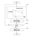
次に、矩形波駆動方式でブラシレスモータ45をセンサレス制御している状態で負荷が急増したときの制御ユニット213の対応処理(電圧制御部としてのソフトウェア機能)を、図4のフローチャートに基づき説明する。
まず、制御ユニット213は、ステップS301で、ブラシレスモータ45の回転動作指令状態であるか停止指令状態であるかを判別する。
次に、矩形波駆動方式でブラシレスモータ45をセンサレス制御している状態で負荷が急増したときの制御ユニット213の対応処理(電圧制御部としてのソフトウェア機能)を、図4のフローチャートに基づき説明する。
まず、制御ユニット213は、ステップS301で、ブラシレスモータ45の回転動作指令状態であるか停止指令状態であるかを判別する。
そして、制御ユニット213は、停止指令状態であれば本ルーチンをそのまま終了させて停止操作状態をそのまま継続させ、回転動作指令状態であればステップS302に進む。
ステップS302で、制御ユニット213は、矩形波駆動方式でブラシレスモータ45をPWM制御している状態であるか否か、換言すれば、ブラシレスモータ45の回転速度の指令値が矩形波駆動方式を採用する低回転速度領域内であるか否かを判別する。
ステップS302で、制御ユニット213は、矩形波駆動方式でブラシレスモータ45をPWM制御している状態であるか否か、換言すれば、ブラシレスモータ45の回転速度の指令値が矩形波駆動方式を採用する低回転速度領域内であるか否かを判別する。
ここで、正弦波駆動方式でブラシレスモータ45をPWM制御している状態である場合、換言すれば、ブラシレスモータ45の回転速度の指令値が正弦波駆動方式を採用する高回転速度領域内である場合、制御ユニット213は、本ルーチンをそのまま終了させて正弦波駆動方式でのブラシレスモータ45の駆動制御を継続する。
一方、矩形波駆動方式でブラシレスモータ45をPWM制御している状態である場合、換言すれば、ブラシレスモータ45の回転速度の指令値が矩形波駆動方式を採用する低回転速度領域内である場合、制御ユニット213は、ステップS303に進む。
そして、制御ユニット213は、ステップS303にて、非通電相の誘起電圧が変化しない時間、又は、通電モードが切り替わらない時間の計測を行う。
そして、制御ユニット213は、ステップS303にて、非通電相の誘起電圧が変化しない時間、又は、通電モードが切り替わらない時間の計測を行う。
非通電相の誘起電圧が変化しない時間とは、所定時間毎にサンプリングされる非通電相の誘起電圧の検出値の前回値と今回値との差が所定値以下になっている状態の継続時間であり、通電モードが切り替わらない時間とは、前回の通電モードの切り替えからの経過時間である。
矩形波駆動方式でブラシレスモータ45をPWM制御している状態で、電動式ウォータポンプ40のポンプ部に異物が噛み込むなどして負荷が急増すると、回転低下に対する印加電圧(入力電圧)の増大制御が間に合わず(回転フィードバック制御の応答遅れにより)、ブラシレスモータ45が停止してしまう場合がある。
矩形波駆動方式でブラシレスモータ45をPWM制御している状態で、電動式ウォータポンプ40のポンプ部に異物が噛み込むなどして負荷が急増すると、回転低下に対する印加電圧(入力電圧)の増大制御が間に合わず(回転フィードバック制御の応答遅れにより)、ブラシレスモータ45が停止してしまう場合がある。
そして、ブラシレスモータ45が停止すると回転速度計測値の更新タイミングである通電モードの切り替えタイミングが検知されなくなることで、停止直前に更新された回転速度計測値がそのまま維持されることになる。
このときに、回転速度の指令値よりも回転速度計測値が高い状態であると、制御ユニット213による回転速度フィードバック制御では、回転速度計測値が更新されないにも関わらずブラシレスモータ45の回転速度を下げようとしてブラシレスモータ45の印加電圧(回転トルク)を下げる操作を行い、負荷の急増によって停止したブラシレスモータ45は停止状態を維持し続けることになる。
このときに、回転速度の指令値よりも回転速度計測値が高い状態であると、制御ユニット213による回転速度フィードバック制御では、回転速度計測値が更新されないにも関わらずブラシレスモータ45の回転速度を下げようとしてブラシレスモータ45の印加電圧(回転トルク)を下げる操作を行い、負荷の急増によって停止したブラシレスモータ45は停止状態を維持し続けることになる。
つまり、ポンプ部への異物の噛み込みなどによって電動式ウォータポンプ40の負荷が増大した場合、回転速度指令値を実現するために回転トルクを増大させる要求があるのに、逆に、制御ユニット213によって回転トルクを下げる操作が実施されることで、ブラシレスモータ45は停止状態を維持することになる。
そして、ブラシレスモータ45が停止状態を維持すると、非通電相の誘起電圧が変化せず、誘起電圧が変化しなければ通電モードの切り替え時期が検出されず通電モードの切り替えは実施されない。
そして、ブラシレスモータ45が停止状態を維持すると、非通電相の誘起電圧が変化せず、誘起電圧が変化しなければ通電モードの切り替え時期が検出されず通電モードの切り替えは実施されない。
制御ユニット213は、上記のように負荷の急増などに伴うモータ停止状態であってブラシレスモータ45が停止し続けている状態であるか否かを判断するために、ステップS303で時間計測を行う。
次いで、制御ユニット213は、ステップS304に進み、ステップS303で計測した時間が所定時間(閾値)TSLに達したか否かを判断する。
次いで、制御ユニット213は、ステップS304に進み、ステップS303で計測した時間が所定時間(閾値)TSLに達したか否かを判断する。
前記所定時間TSLは、非通電相の誘起電圧が変化しない時間、又は、通電モードが切り替わらない時間から、ブラシレスモータ45が停止し続けている状態を可及的速やかに検出できる値として、予め適合されている。
そして、ステップS303で計測した時間が所定時間TSLに達していない場合、制御ユニット213は、ブラシレスモータ45が停止し続けている状態ではないと判断し、本ルーチンを終了させることで、ブラシレスモータ45の回転速度の計測値と回転速度指令との差に応じて印加電圧を決定する矩形波駆動方式でのPWM制御を継続する。
そして、ステップS303で計測した時間が所定時間TSLに達していない場合、制御ユニット213は、ブラシレスモータ45が停止し続けている状態ではないと判断し、本ルーチンを終了させることで、ブラシレスモータ45の回転速度の計測値と回転速度指令との差に応じて印加電圧を決定する矩形波駆動方式でのPWM制御を継続する。
一方、ステップS303で計測した時間が所定時間TSLに達した場合、制御ユニット213は、ブラシレスモータ45が停止し続けている状態であると判断してステップS305に進む。
ステップS305で、制御ユニット213は、ブラシレスモータ45の回転速度の計測値と回転速度指令との差に基づく印加電圧の設定処理を補正することで、ブラシレスモータ45に印加する電圧(入力電圧)を上昇させる。
ステップS305で、制御ユニット213は、ブラシレスモータ45の回転速度の計測値と回転速度指令との差に基づく印加電圧の設定処理を補正することで、ブラシレスモータ45に印加する電圧(入力電圧)を上昇させる。
つまり、ブラシレスモータ45の回転速度の計測値が更新されない状態で、回転速度の計測値と回転速度指令値との差(制御偏差)に基づく通常の設定処理によって印加電圧を決定しても、停止状態のブラシレスモータ45を起動させることができないので、制御ユニット213は、通常の設定処理を補正してブラシレスモータ45に印加する電圧(入力電圧)を上昇変化させる(通常の設定処理よりも印加電圧を高くする)ことで、負荷の増大によって停止したブラシレスモータ45を再起動させる。
[回転速度指令値の増大補正]
ステップS305における印加電圧を上昇させる処理として、制御ユニット213は、回転速度フィードバック制御に用いる回転速度指令値(目標回転速度)を一時的に増大補正する処理を実施することができる。
図5のフローチャートは、ステップS305の印加電圧の上昇処理として、回転速度指令値を増大補正する処理の一態様を示す。
ステップS305における印加電圧を上昇させる処理として、制御ユニット213は、回転速度フィードバック制御に用いる回転速度指令値(目標回転速度)を一時的に増大補正する処理を実施することができる。
図5のフローチャートは、ステップS305の印加電圧の上昇処理として、回転速度指令値を増大補正する処理の一態様を示す。
まず、制御ユニット213は、ステップS401にて、モータ回転停止によって停止前の値が更新されずに保持されている回転速度の計測値と、回転速度指令値とのうちの高い方を基準回転速度NBとして選択する。
次いで、制御ユニット213は、ステップS402に進み、ステップS401にて設定した基準回転速度NBに所定の加算補正分NHOSを加算した結果を、印加電圧を上昇させてモータを再起動させるために一時的に用いるサブ指令値として設定する。
次いで、制御ユニット213は、ステップS402に進み、ステップS401にて設定した基準回転速度NBに所定の加算補正分NHOSを加算した結果を、印加電圧を上昇させてモータを再起動させるために一時的に用いるサブ指令値として設定する。
そして、冷却水温度などから設定される回転速度指令値(メイン指令値)に基づく印加電圧の設定処理から、サブ指令値(サブ指令値=NB+NHOS)と回転速度の計測値との偏差に基づき印加電圧を決定する処理に移行する。
なお、サブ指令値に基づく回転速度フィードバック制御は、後述するサブ指令値を漸減させる処理によってサブ指令値がメイン指令値に一致するようになった時点でキャンセルされ、冷却水温度などから設定される回転速度指令値(メイン指令値)に基づく印加電圧の設定処理に戻る。
なお、サブ指令値に基づく回転速度フィードバック制御は、後述するサブ指令値を漸減させる処理によってサブ指令値がメイン指令値に一致するようになった時点でキャンセルされ、冷却水温度などから設定される回転速度指令値(メイン指令値)に基づく印加電圧の設定処理に戻る。
例えば、回転速度の計測値が回転速度指令値(メイン指令値)よりも高い状態で負荷が急増してモータが停止し、指令値よりも高い状態で計測値が更新されなくなった場合、制御ユニット213は、基準回転速度NBとして回転速度の計測値を選択する。
そして、制御ユニット213は、サブ指令値を基準回転速度NBよりも高い回転速度に設定するから、サブ指令値は、更新が停止している計測値よりも高い回転速度に設定されることになり、サブ指令値を用いる回転速度フィードバック制御では、サブ指令値に計測値を近づけようとして(換言すれば、モータ回転速度を上げようとして)印加電圧を上昇させることになる。
そして、制御ユニット213は、サブ指令値を基準回転速度NBよりも高い回転速度に設定するから、サブ指令値は、更新が停止している計測値よりも高い回転速度に設定されることになり、サブ指令値を用いる回転速度フィードバック制御では、サブ指令値に計測値を近づけようとして(換言すれば、モータ回転速度を上げようとして)印加電圧を上昇させることになる。
これにより、制御ユニット213は、急増した負荷に抗する回転トルクを発生させてブラシレスモータ45を再起動させることができ(噛み込んだ異物の除去を図ることができ)、電動式ウォータポンプ40が停止状態に維持されてしまうことを抑止できる。
したがって、制御ユニット213は、電動式ウォータポンプ40を極低回転速度に制御しているときに、異物の混入などによって負荷が急増して電動式ウォータポンプ40が停止しても、電動式ウォータポンプ40を直ぐに再起動させて冷却水の循環を継続させることができる。
したがって、制御ユニット213は、電動式ウォータポンプ40を極低回転速度に制御しているときに、異物の混入などによって負荷が急増して電動式ウォータポンプ40が停止しても、電動式ウォータポンプ40を直ぐに再起動させて冷却水の循環を継続させることができる。
そして、電動式ウォータポンプ40が停止状態を維持することを抑止できれば、冷却水が滞留することによるヒートスポットの発生を抑止でき、制御ユニット213は、水温センサ81,82による検出結果に基づき内燃機関10の暖機進行状態を精度良く検知して、冷却水の循環経路の制御や電動式ウォータポンプ40の吐出量の制御を適切に行え、以って、電動式ウォータポンプ40に異物が混入したときの内燃機関10の運転性の低下を抑制できる。
なお、制御ユニット213は、サブ指令値を、メイン指令値よりも所定回転速度だけ高い速度に設定することができるが、上記のように、回転速度の計測値と回転速度指令値との高い方を基準回転速度NBとし、この基準回転速度NBよりも所定回転速度だけ高い速度をサブ指令値とすれば、計測値よりも高くかつ高過ぎないサブ指令値を安定して設定できる。
なお、制御ユニット213は、サブ指令値を、メイン指令値よりも所定回転速度だけ高い速度に設定することができるが、上記のように、回転速度の計測値と回転速度指令値との高い方を基準回転速度NBとし、この基準回転速度NBよりも所定回転速度だけ高い速度をサブ指令値とすれば、計測値よりも高くかつ高過ぎないサブ指令値を安定して設定できる。
制御ユニット213は、ステップS402で、回転速度フィードバック制御に用いる回転速度指令値を増大補正する処理を実施すると、次いでステップS403に進み、再起動したブラシレスモータ45の回転速度がサブ指令値よりも低くメイン指令値よりも高い第1回転速度N1にまで上昇したか否かを判別する。
そして、制御ユニット213は、ブラシレスモータ45の回転速度が第1回転速度N1に達するまでステップS403の判別を繰り返すことで、サブ指令値を初期値のままに保持し、ブラシレスモータ45の回転速度が第1回転速度N1に達すると、ステップS404に進む。
そして、制御ユニット213は、ブラシレスモータ45の回転速度が第1回転速度N1に達するまでステップS403の判別を繰り返すことで、サブ指令値を初期値のままに保持し、ブラシレスモータ45の回転速度が第1回転速度N1に達すると、ステップS404に進む。
ステップS404で、制御ユニット213は、サブ指令値の前回値から第1減少補正分ΔN1だけ低下させた回転速度を新たなサブ指令値とする処理を実施してサブ指令値を漸減させ、この漸減されるサブ指令値が回転速度フィードバック制御に用いられるようにする。
次いで、次のステップS405で、制御ユニット213は、漸減処理されるサブ指令値が、前記第1回転速度N1よりも低くメイン指令値よりも高い第2回転速度N2にまで低下したか否かを判別する。
次いで、次のステップS405で、制御ユニット213は、漸減処理されるサブ指令値が、前記第1回転速度N1よりも低くメイン指令値よりも高い第2回転速度N2にまで低下したか否かを判別する。
サブ指令値が第2回転速度N2よりも高い場合、制御ユニット213は、ステップS404に戻り、サブ指令値が第2回転速度N2にまで低下するまでの間、所定時間毎にサブ指令値を第1減少補正分ΔN1だけ低下させる処理を繰り返す。
そして、制御ユニット213は、ステップS405で、サブ指令値が第2回転速度N2にまで低下したことを判別すると、ステップS406に進み、サブ指令値の前回値から第2減少補正分ΔN2だけ低下させた回転速度を新たなサブ指令値とする処理を実施し、サブ指令値を漸減させる。
そして、制御ユニット213は、ステップS405で、サブ指令値が第2回転速度N2にまで低下したことを判別すると、ステップS406に進み、サブ指令値の前回値から第2減少補正分ΔN2だけ低下させた回転速度を新たなサブ指令値とする処理を実施し、サブ指令値を漸減させる。
ここで、第2減少補正分ΔN2は、絶対値が第1減少補正分ΔN1よりも小さい値に設定され、これにより、サブ指令値が第2回転速度N2にまで低下した後は、サブ指令値が第2回転速度N2に低下するまでよりもサブ指令値の減少速度が遅くなる。
制御ユニット213は、ステップS406でサブ指令値の減少速度を切り替えると、ステップS407に進み、サブ指令値がメイン指令値にまで低下したか否かを判別し、サブ指令値がメイン指令値よりも高い間は、ステップS406に戻って所定時間毎にサブ指令値を第2減少補正分ΔN2だけ低下させる処理を繰り返す。
制御ユニット213は、ステップS406でサブ指令値の減少速度を切り替えると、ステップS407に進み、サブ指令値がメイン指令値にまで低下したか否かを判別し、サブ指令値がメイン指令値よりも高い間は、ステップS406に戻って所定時間毎にサブ指令値を第2減少補正分ΔN2だけ低下させる処理を繰り返す。
つまり、制御ユニット213は、サブ指令値をメイン指令値まで漸減させるが、その途中でサブ指令値の減少速度をより遅い速度に切り替える処理を実施する。
そして、サブ指令値がメイン指令値にまで低下すると、制御ユニット213は、ステップS408に進み、サブ指令値に基づく制御をキャンセルし、メイン指令値に基づく制御に復帰させる。
そして、サブ指令値がメイン指令値にまで低下すると、制御ユニット213は、ステップS408に進み、サブ指令値に基づく制御をキャンセルし、メイン指令値に基づく制御に復帰させる。
上記のようにしてサブ指令値を漸減させれば、サブ指令値の初期値にモータ回転速度を近づける制御によってブラシレスモータ45の動き出しを補償しつつ、回転速度が第1回転速度N1(メイン指令値<N1<サブ指令値の初期値)まで上昇するとサブ指令値の漸減を開始することで、ブラシレスモータ45の回転速度が過剰に高くなることを抑制できる。
また、サブ指令値をメイン指令値にまで漸減させるときに、漸減開始直後は速い速度でサブ指令値を低下させ、メイン指令値に近づくとサブ指令値の減少速度を遅くするので、ブラシレスモータ45の回転速度が過剰に高くなることを抑制しつつ、異物の混入状態で急激に指令値が低下して回転トルクが急減することでモータ回転が不安定になることを抑制できる。
なお、図5のフローチャートに示す処理で、制御ユニット213は、サブ指令値の減少速度の切り替えを1回だけ実施して減少速度を段階的により遅くするが、減少速度の切替えを2回以上行うことができる。
なお、図5のフローチャートに示す処理で、制御ユニット213は、サブ指令値の減少速度の切り替えを1回だけ実施して減少速度を段階的により遅くするが、減少速度の切替えを2回以上行うことができる。
図6のタイムチャートは、図5のフローチャートに示す処理を実施するときの回転速度指令値の変化を例示する。
時刻t1で、非通電相の誘起電圧が変化しない時間、又は、通電モードが切り替わらない時間が所定時間TSLに達すると、制御ユニット213は、回転速度指令値をメイン指令値からステップ的に増大させる処理を実施する。
時刻t1で、非通電相の誘起電圧が変化しない時間、又は、通電モードが切り替わらない時間が所定時間TSLに達すると、制御ユニット213は、回転速度指令値をメイン指令値からステップ的に増大させる処理を実施する。
その後、ブラシレスモータ45が再駆動されて回転速度計測値が更新されるようになり、時刻t2で回転速度計測値がN1にまで上昇すると、制御ユニット213は、回転速度指令値の増大補正値の減少処理を開始し、回転速度指令値(サブ指令値)を漸減させる。
そして、回転速度指令値がN2まで低下すると、制御ユニット213は、それまでよりも回転速度指令値の減少速度を遅く変更し、時刻t4にてメイン指令値にまで低下すると、メイン指令値に基づく通常制御に復帰する。
そして、回転速度指令値がN2まで低下すると、制御ユニット213は、それまでよりも回転速度指令値の減少速度を遅く変更し、時刻t4にてメイン指令値にまで低下すると、メイン指令値に基づく通常制御に復帰する。
[回転速度計測値の減少補正]
また、ステップS305における印加電圧を上昇させる処理として、制御ユニット213は、回転速度フィードバック制御に用いる回転速度計測値を減少補正する処理を実施することができる。
図7のフローチャートは、ステップS305の印加電圧の上昇処理として、回転速度計測値を減少補正する処理の一態様を示す。
また、ステップS305における印加電圧を上昇させる処理として、制御ユニット213は、回転速度フィードバック制御に用いる回転速度計測値を減少補正する処理を実施することができる。
図7のフローチャートは、ステップS305の印加電圧の上昇処理として、回転速度計測値を減少補正する処理の一態様を示す。
図7のフローチャートにおいて、制御ユニット213は、ステップS501で、非通電相の誘起電圧が変化しない時間又は通電モードが切り替わらない時間が前記所定時間TSLに達してからの経過時間が長くなるほど回転速度計測値をより低く補正する。換言すれば、回転速度計測値を減少補正するための補正値を、所定時間TSLに達してからの経過時間が長くなるほどより大きな値に変更する。
そして、次のステップS502で、制御ユニット213は、補正した回転速度計測値と回転速度指令値との比較に基づきPWM制御のデューティ比を決定する。
そして、次のステップS502で、制御ユニット213は、補正した回転速度計測値と回転速度指令値との比較に基づきPWM制御のデューティ比を決定する。
更に、ステップS503で、制御ユニット213は、非通電相の誘起電圧が変化するようになって、通電モードの切り替えが実施されるようになったか否か、換言すれば、ブラシレスモータ45が再起動したか否かを判別する。
そして、ブラシレスモータ45が再起動すると、制御ユニット213は、ステップS504に進み、回転速度計測値の減少補正をキャンセルし(若しくは、減少補正量を徐々に小さくし)、回転速度の計測結果をそのまま用いた通常制御に復帰させる。
そして、ブラシレスモータ45が再起動すると、制御ユニット213は、ステップS504に進み、回転速度計測値の減少補正をキャンセルし(若しくは、減少補正量を徐々に小さくし)、回転速度の計測結果をそのまま用いた通常制御に復帰させる。
係る構成によると、急激な負荷の増大に回転速度フィードバック制御が間に合わずブラシレスモータ45が停止し、回転速度計測値が更新されずに指令値よりも高い値のままになっていても、制御ユニット213は、回転速度フィードバック制御(PWM制御)に用いる回転速度計測値を、ブラシレスモータ45の位置情報の検出がない状態で強制的に徐々に低下させる。
これにより、回転速度フィードバック制御に用いる回転速度計測値が指令値よりも高い状態から時間経過に伴って指令値よりも低くなり、回転速度計測値が指令値よりも低くなることで、制御ユニット213は回転速度フィードバック制御によって回転速度計測値を指令値にまで上昇させようとするため、ブラシレスモータ45を再起動させることができる。
これにより、回転速度フィードバック制御に用いる回転速度計測値が指令値よりも高い状態から時間経過に伴って指令値よりも低くなり、回転速度計測値が指令値よりも低くなることで、制御ユニット213は回転速度フィードバック制御によって回転速度計測値を指令値にまで上昇させようとするため、ブラシレスモータ45を再起動させることができる。
したがって、指令値よりも高い回転速度の計測値がそのまま保持される状態でブラシレスモータ45が停止しても、制御ユニット213は、ブラシレスモータ45を再起動させることができ、電動式ウォータポンプ40が停止状態を継続することが抑止される。
[印加電圧指令値の増大補正]
また、ステップS305における印加電圧を上昇させる処理として、制御ユニット213は、回転速度フィードバック制御により決定した印加電圧指令値(入力電圧指令値)を増大補正する処理を実施することができる。
図8のフローチャートは、ステップS305の印加電圧の上昇処理として、印加電圧指令値を増大補正する処理の一態様を示す。
また、ステップS305における印加電圧を上昇させる処理として、制御ユニット213は、回転速度フィードバック制御により決定した印加電圧指令値(入力電圧指令値)を増大補正する処理を実施することができる。
図8のフローチャートは、ステップS305の印加電圧の上昇処理として、印加電圧指令値を増大補正する処理の一態様を示す。
図8のフローチャートにおいて、制御ユニット213は、ステップS601で、非通電相の誘起電圧が変化しない時間又は通電モードが切り替わらない時間が前記所定時間TSLに達してからの経過時間が長くなるほど、印加電圧指令値を増大補正するための電圧補正値(電圧補正値>0)をより大きな値に設定する。
但し、印加電圧指令値の補正値は、予め上限値が設定されていて、時間経過に伴って上限値に達した後は上限値を保持するものとする。
但し、印加電圧指令値の補正値は、予め上限値が設定されていて、時間経過に伴って上限値に達した後は上限値を保持するものとする。
次いで、制御ユニット213は、ステップS602に進み、ブラシレスモータ45の回転速度の計測値と回転速度指令との偏差に基づき演算した印加電圧指令値に、ステップS601で設定した電圧補正値を加算して増大補正し、補正後の印加電圧指令値に基づき指令デューティ比を決定する。
係る印加電圧指令値の増大補正によって、回転速度の計測値及び回転速度指令値(換言すれば、制御偏差)が一定に保持される状態であっても、ブラシレスモータ45に印加される電圧(入力電圧)が増大し、ブラシレスモータ45は再起動されることになる。
係る印加電圧指令値の増大補正によって、回転速度の計測値及び回転速度指令値(換言すれば、制御偏差)が一定に保持される状態であっても、ブラシレスモータ45に印加される電圧(入力電圧)が増大し、ブラシレスモータ45は再起動されることになる。
次のステップS603で、制御ユニット213は、非通電相の誘起電圧が変化し、通電モードの切り替えタイミングが検出されるようになったか否か、換言すれば、ブラシレスモータ45が停止状態から再起動したか否かを判別する。
そして、ブラシレスモータ45が再起動して、非通電相の誘起電圧が変化し始め、通電モードの切り替えが実施されるようになると、制御ユニット213は、ステップS604に進み、印加電圧指令値の増大補正をキャンセルし(若しくは、印加電圧指令値の増大補正量を徐々に小さくし)、回転速度フィードバック制御によって決定された印加電圧指令値をそのまま用いて指令デューティ比を決定する通常制御に復帰させる。
そして、ブラシレスモータ45が再起動して、非通電相の誘起電圧が変化し始め、通電モードの切り替えが実施されるようになると、制御ユニット213は、ステップS604に進み、印加電圧指令値の増大補正をキャンセルし(若しくは、印加電圧指令値の増大補正量を徐々に小さくし)、回転速度フィードバック制御によって決定された印加電圧指令値をそのまま用いて指令デューティ比を決定する通常制御に復帰させる。
[回転速度指令値の下限値の増大補正]
ところで、制御ユニット213が、ステップS305における印加電圧を上昇させる処理を実施してブラシレスモータ45を再起動させることができても、例えば異物を除去できていない状態では、印加電圧を上昇させる処理をキャンセルすることで再度ブラシレスモータ45が停止し、ブラシレスモータ45の停止と、印加電圧を上昇させる処理による再起動とが繰り返されてしまう場合がある。
そこで、制御ユニット213は、ブラシレスモータ45の停止、再起動が繰り返されることを抑制するための処理として、図9のフローチャートに示した、回転速度指令値の下限値の増大補正処理(換言すれば、繰り返し抑制のための指令値の増大補正処理)を実施することができる。
図9のフローチャートにおいて、制御ユニット213は、ステップS701で、ブラシレスモータ45の停止と印加電圧を上昇させる処理による再起動とが繰り返されているか否かを判別する。
例えば、制御ユニット213は、ステップS305の印加電圧を上昇させる処理を停止した後から所定時間内に再度ステップS305を実施したときに繰り返し回数をインクリメントし、ステップS305の印加電圧を上昇させる処理を停止した後から所定時間内に再度ステップS305を実施しなかったときには繰り返し回数を零にリセットする。
例えば、制御ユニット213は、ステップS305の印加電圧を上昇させる処理を停止した後から所定時間内に再度ステップS305を実施したときに繰り返し回数をインクリメントし、ステップS305の印加電圧を上昇させる処理を停止した後から所定時間内に再度ステップS305を実施しなかったときには繰り返し回数を零にリセットする。
そして、制御ユニット213は、前記繰り返し回数が所定回数(所定回数>2)に達したときに、ブラシレスモータ45の停止と印加電圧を上昇させる処理による再起動とが繰り返されていると判断する。
ブラシレスモータ45の停止と再起動とが所定以上の頻度で繰り返されている場合、制御ユニット213は、ステップS702に進み、回転速度指令値の下限値を初期値(基準値)より高い速度に増大補正する。換言すれば、ステップS305の印加電圧を上昇させる処理をキャンセルした後の制御に用いる回転速度指令値を、メイン指令値よりも高い繰り返し時用の値に設定する。
ブラシレスモータ45の停止と再起動とが所定以上の頻度で繰り返されている場合、制御ユニット213は、ステップS702に進み、回転速度指令値の下限値を初期値(基準値)より高い速度に増大補正する。換言すれば、ステップS305の印加電圧を上昇させる処理をキャンセルした後の制御に用いる回転速度指令値を、メイン指令値よりも高い繰り返し時用の値に設定する。
ここで、制御ユニット213は、前記繰り返し回数が多くなるほど下限値(繰り返し時用の指令値)をより高い回転速度に変更することができる。
制御ユニット213は、冷却水温度などに基づき演算した回転速度指令値(メイン指令値)が前記下限値を下回る場合、冷却水温度などに基づき演算した回転速度指令値に代えて前記下限値を回転速度フィードバック制御に用いる指令値として選択する。
制御ユニット213は、冷却水温度などに基づき演算した回転速度指令値(メイン指令値)が前記下限値を下回る場合、冷却水温度などに基づき演算した回転速度指令値に代えて前記下限値を回転速度フィードバック制御に用いる指令値として選択する。
制御ユニット213が、回転速度指令値の下限値をより高くし、より高い回転速度でブラシレスモータ45を回転駆動させることで、負荷が急激に増大したときに回転速度フィードバック制御の応答遅れによってブラシレスモータ45が停止してしまうことが抑制され、以って、停止/再起動が繰り返されることが抑制される。
なお、制御ユニット213は、下限値をステップ的に増大変更した後に、下限値を増大変更時よりも遅い速度で(増大変更時よりも小さいステップ幅で)漸減させ、過剰に高い回転速度指令値に保持されることを抑制することができる。
なお、制御ユニット213は、下限値をステップ的に増大変更した後に、下限値を増大変更時よりも遅い速度で(増大変更時よりも小さいステップ幅で)漸減させ、過剰に高い回転速度指令値に保持されることを抑制することができる。
図10のタイムチャートは、図9のフローチャートに示した処理によって回転指令下限値が変更される様子を例示する。
時刻t11で、モータ停止に伴って印加電圧を増大補正する処理として回転指令値を増大補正する処理が実施され、係る処理によってモータが再起動し、時刻t12で回転指令値をメイン指令値に戻したもののモータが再度停止したため、時刻t13にて再度回転指令値が増大補正される。
時刻t11で、モータ停止に伴って印加電圧を増大補正する処理として回転指令値を増大補正する処理が実施され、係る処理によってモータが再起動し、時刻t12で回転指令値をメイン指令値に戻したもののモータが再度停止したため、時刻t13にて再度回転指令値が増大補正される。
その後、モータが再起動し、時刻t14で回転指令値をメイン指令値に戻したもののモータが再度停止したため、時刻t15にて再度回転指令値が増大補正されるが、停止/再起動の繰り返し状態であることが検知されて回転指令値の下限値が増大補正され、時刻t16にて通常制御に復帰したときの回転指令値は、メイン指令値よりも高い下限値に設定される。
上記実施形態で説明した各技術的思想は、矛盾が生じない限りにおいて、適宜組み合わせて使用することができる。
つまり、回転速度指令値の増大補正、回転速度計測値の減少補正、印加電圧指令値の増大補正のうちの複数を並行して実施することができる。
つまり、回転速度指令値の増大補正、回転速度計測値の減少補正、印加電圧指令値の増大補正のうちの複数を並行して実施することができる。
また、好ましい実施形態を参照して本発明の内容を具体的に説明したが、本発明の基本的技術思想及び教示に基づいて、当業者であれば、種々の変形態様を採り得ることは自明である。
上記実施形態のブラシレスモータ45は、電動式ウォータポンプ40の駆動源として用いられるが、例えば、オイルポンプの駆動源として用いられるブラシレスモータについても同様の処理を実施することで同様の作用効果が得られることは明らかであり、ブラシレスモータ45は電動式ウォータポンプ40の駆動源に限定されない。
上記実施形態のブラシレスモータ45は、電動式ウォータポンプ40の駆動源として用いられるが、例えば、オイルポンプの駆動源として用いられるブラシレスモータについても同様の処理を実施することで同様の作用効果が得られることは明らかであり、ブラシレスモータ45は電動式ウォータポンプ40の駆動源に限定されない。
また、電動式ウォータポンプ40が一旦停止して再起動したときに、制御ユニット213は、停止期間及び再起動直後の所定期間において検出された冷却水温度を制御に用いないようにしたり、停止期間及び再起動直後の所定期間における冷却水温度の変化を推定し、推定値に基づいて冷却制御を行うことができる。
また、制御ユニット213は、印加電圧指令値の増大補正に代えて印加電圧指令値に基づくデューティ比指令値を増大補正することができる。つまり、制御ユニット213は、誘起電圧が変化しない時間又は通電モードが切り替わらない時間が所定時間に達したときに、ブラシレスモータ45の入力電圧をモータ停止時点から上昇変化させる種々の処理を採用できる。
ここで、上述した実施形態から把握し得る技術的思想について、以下に記載する。
ブラシレスモータの制御装置は、その一態様において、ブラシレスモータの複数相のうちでパルス幅変調動作によって通電する相を選択する複数の通電モードを有し、前記複数の通電モードを非通電相の誘起電圧と閾値との比較に基づき切り替えて、前記ブラシレスモータの回転速度を制御する制御装置において、前記誘起電圧が変化しない時間又は前記通電モードが切り替わらない時間が所定時間に達したときに前記ブラシレスモータの入力電圧を上昇させる電圧制御部を備える。
ブラシレスモータの制御装置は、その一態様において、ブラシレスモータの複数相のうちでパルス幅変調動作によって通電する相を選択する複数の通電モードを有し、前記複数の通電モードを非通電相の誘起電圧と閾値との比較に基づき切り替えて、前記ブラシレスモータの回転速度を制御する制御装置において、前記誘起電圧が変化しない時間又は前記通電モードが切り替わらない時間が所定時間に達したときに前記ブラシレスモータの入力電圧を上昇させる電圧制御部を備える。
前記制御装置の好ましい態様において、前記電圧制御部は、前記誘起電圧が変化しない時間又は前記通電モードが切り替わらない時間が所定時間に達したときに前記ブラシレスモータの回転速度の指令値を一時的に増大補正する。
別の好ましい態様では、前記電圧制御部は、前記ブラシレスモータの回転速度の指令値と、前記ブラシレスモータの回転速度の計測データとのより高い方の回転速度を増大補正して、前記ブラシレスモータの回転速度の制御に用いる指令値とする。
別の好ましい態様では、前記電圧制御部は、前記ブラシレスモータの回転速度の指令値と、前記ブラシレスモータの回転速度の計測データとのより高い方の回転速度を増大補正して、前記ブラシレスモータの回転速度の制御に用いる指令値とする。
さらに別の好ましい態様では、前記電圧制御部は、前記回転速度の指令値を増大させた後に前記ブラシレスモータの回転速度が所定速度に達した後に前記回転速度の指令値の増大補正量を漸減させて増大補正前の指令値に戻す。
さらに別の好ましい態様では、前記電圧制御部は、前記回転速度の指令値の増大補正が繰り返されるときに前記指令値の下限値を上昇させる。
さらに別の好ましい態様では、前記電圧制御部は、前記回転速度の指令値の増大補正が繰り返されるときに前記指令値の下限値を上昇させる。
さらに別の好ましい態様では、前記電圧制御部は、前記誘起電圧が変化しない時間又は前記通電モードが切り替わらない時間が所定時間に達したときに、前記ブラシレスモータの回転速度の計測データを減少補正して前記回転速度の制御に用いる。
さらに別の好ましい態様では、前記電圧制御部は、前記誘起電圧が変化しない時間又は前記通電モードが切り替わらない時間が所定時間に達したときに、前記回転速度の制御による前記ブラシレスモータの入力電圧に補正電圧を付加して増大させる。
さらに別の好ましい態様では、前記電圧制御部は、前記誘起電圧が変化しない時間又は前記通電モードが切り替わらない時間が所定時間に達したときに、前記回転速度の制御による前記ブラシレスモータの入力電圧に補正電圧を付加して増大させる。
また、ブラシレスモータの制御方法は、その一態様において、ブラシレスモータの複数相のうちでパルス幅変調動作によって通電する相を選択する複数の通電モードを有し、前記複数の通電モードを非通電相の誘起電圧と閾値との比較に基づき切り替えて、前記ブラシレスモータの回転速度を制御する方法であって、前記誘起電圧が変化しない時間又は前記通電モードが切り替わらない時間を計測するステップと、前記計測時間が所定時間に達したときに前記ブラシレスモータの入力電圧を上昇させるステップと、を含む。
40…電動式ウォータポンプ、45…ブラシレスモータ、100…制御装置、212…モータ駆動回路、213…制御ユニット、213a…A/D変換器、213b…マイクロコンピュータ、215u,215v,215w…巻線、216…永久磁石回転子、217a~217f…スイッチング素子
Claims (8)
- ブラシレスモータの複数相のうちでパルス幅変調動作によって通電する相を選択する複数の通電モードを有し、前記複数の通電モードを非通電相の誘起電圧と閾値との比較に基づき切り替えて、前記ブラシレスモータの回転速度を制御する制御装置において、
前記誘起電圧が変化しない時間又は前記通電モードが切り替わらない時間が所定時間に達したときに前記ブラシレスモータの入力電圧を上昇させる電圧制御部を備えた、ブラシレスモータの制御装置。 - 前記電圧制御部は、前記誘起電圧が変化しない時間又は前記通電モードが切り替わらない時間が所定時間に達したときに前記ブラシレスモータの回転速度の指令値を一時的に増大補正する、請求項1記載のブラシレスモータの制御装置。
- 前記電圧制御部は、前記ブラシレスモータの回転速度の指令値と、前記ブラシレスモータの回転速度の計測データとのより高い方の回転速度を増大補正して、前記ブラシレスモータの回転速度の制御に用いる指令値とする、請求項2記載のブラシレスモータの制御装置。
- 前記電圧制御部は、前記回転速度の指令値を増大させた後に前記ブラシレスモータの回転速度が所定速度に達した後に前記回転速度の指令値の増大補正量を漸減させて増大補正前の指令値に戻す、請求項2記載のブラシレスモータの制御装置。
- 前記電圧制御部は、前記回転速度の指令値の増大補正が繰り返されるときに前記指令値の下限値を上昇させる、請求項2記載のブラシレスモータの制御装置。
- 前記電圧制御部は、前記誘起電圧が変化しない時間又は前記通電モードが切り替わらない時間が所定時間に達したときに、前記ブラシレスモータの回転速度の計測データを減少補正して前記回転速度の制御に用いる、請求項1記載のブラシレスモータの制御装置。
- 前記電圧制御部は、前記誘起電圧が変化しない時間又は前記通電モードが切り替わらない時間が所定時間に達したときに、前記回転速度の制御による前記ブラシレスモータの入力電圧に補正電圧を付加して増大させる、請求項1記載のブラシレスモータの制御装置。
- ブラシレスモータの複数相のうちでパルス幅変調動作によって通電する相を選択する複数の通電モードを有し、前記複数の通電モードを非通電相の誘起電圧と閾値との比較に基づき切り替えて、前記ブラシレスモータの回転速度を制御する制御する方法であって、
前記誘起電圧が変化しない時間又は前記通電モードが切り替わらない時間を計測するステップと、
前記計測時間が所定時間に達したときに前記ブラシレスモータの入力電圧を上昇させるステップと、
を含む、ブラシレスモータの制御方法。
Priority Applications (3)
| Application Number | Priority Date | Filing Date | Title |
|---|---|---|---|
| CN201780003349.2A CN108156835B (zh) | 2016-10-04 | 2017-10-03 | 无刷马达的控制装置以及控制方法 |
| DE112017005029.4T DE112017005029T5 (de) | 2016-10-04 | 2017-10-03 | Steuervorrichtung und Verfahren für bürstenlosen Motor |
| US15/759,695 US10447182B2 (en) | 2016-10-04 | 2017-10-03 | Control device and method for brushless motor |
Applications Claiming Priority (2)
| Application Number | Priority Date | Filing Date | Title |
|---|---|---|---|
| JP2016196679A JP6661509B2 (ja) | 2016-10-04 | 2016-10-04 | ブラシレスモータの制御装置及び制御方法 |
| JP2016-196679 | 2016-10-04 |
Publications (1)
| Publication Number | Publication Date |
|---|---|
| WO2018066566A1 true WO2018066566A1 (ja) | 2018-04-12 |
Family
ID=61831070
Family Applications (1)
| Application Number | Title | Priority Date | Filing Date |
|---|---|---|---|
| PCT/JP2017/036005 Ceased WO2018066566A1 (ja) | 2016-10-04 | 2017-10-03 | ブラシレスモータの制御装置及び制御方法 |
Country Status (5)
| Country | Link |
|---|---|
| US (1) | US10447182B2 (ja) |
| JP (1) | JP6661509B2 (ja) |
| CN (1) | CN108156835B (ja) |
| DE (1) | DE112017005029T5 (ja) |
| WO (1) | WO2018066566A1 (ja) |
Families Citing this family (6)
| Publication number | Priority date | Publication date | Assignee | Title |
|---|---|---|---|---|
| EP3427910B1 (en) * | 2017-07-14 | 2020-08-19 | Braun GmbH | Method for determining the time behavior of a cyclic motor process during use of an electrical hair removal device and hair removal device |
| EP3750670B1 (en) * | 2018-03-28 | 2023-03-29 | Nanjing Chervon Industry Co., Ltd. | Electric power tool and control method therefor |
| JP7392362B2 (ja) * | 2019-09-30 | 2023-12-06 | ニデックパワートレインシステムズ株式会社 | モータ駆動装置及び電動オイルポンプ装置 |
| JP7530817B2 (ja) * | 2020-12-17 | 2024-08-08 | ミネベアミツミ株式会社 | モータ駆動制御装置、ファンシステム、およびモータの異常判定方法 |
| CN113364359B (zh) * | 2021-05-13 | 2024-07-05 | 联合汽车电子有限公司 | 无位置传感器控制方法、装置及存储介质 |
| CN115370458B (zh) * | 2021-05-18 | 2023-08-15 | 广州汽车集团股份有限公司 | 发动机冷却系统、方法、车辆控制系统、车辆和存储介质 |
Citations (4)
| Publication number | Priority date | Publication date | Assignee | Title |
|---|---|---|---|---|
| JP2004353624A (ja) * | 2003-05-30 | 2004-12-16 | Aisin Seiki Co Ltd | 電動液体ポンプの制御方法および装置 |
| JP2007202294A (ja) * | 2006-01-26 | 2007-08-09 | Valeo Thermal Systems Japan Corp | センサレス・ブラシレスモータの駆動制御方法及びその装置 |
| JP2008029122A (ja) * | 2006-07-21 | 2008-02-07 | Aisan Ind Co Ltd | センサレスブラシレスモータの制御装置 |
| JP2015015788A (ja) * | 2013-07-03 | 2015-01-22 | 株式会社ジェイテクト | ブラシレスモータの制御装置 |
Family Cites Families (11)
| Publication number | Priority date | Publication date | Assignee | Title |
|---|---|---|---|---|
| ATE463073T1 (de) * | 2007-07-26 | 2010-04-15 | Baumueller Nuernberg Gmbh | System zur lage- und geschwindigkeitsermittlung bei einem permanentmagnet-läufer einer elektrischen maschine |
| JP5175569B2 (ja) | 2008-02-07 | 2013-04-03 | ルネサスエレクトロニクス株式会社 | 同期電動機の駆動システム |
| JP2009261041A (ja) * | 2008-04-11 | 2009-11-05 | Hitachi Ltd | 同期モータおよび同期モータの制御方法 |
| US8710788B2 (en) * | 2010-03-23 | 2014-04-29 | Hitachi Automotive Systems, Ltd. | Brushless motor drive apparatus and drive method |
| JP5970227B2 (ja) * | 2012-04-17 | 2016-08-17 | 日立オートモティブシステムズ株式会社 | 同期電動機の駆動システム |
| JP5597683B2 (ja) * | 2012-09-21 | 2014-10-01 | 本田技研工業株式会社 | 電源装置 |
| JP6145274B2 (ja) * | 2013-01-18 | 2017-06-07 | 日立オートモティブシステムズ株式会社 | ブラシレスモータの駆動装置 |
| JP6030466B2 (ja) * | 2013-02-06 | 2016-11-24 | 日立オートモティブシステムズ株式会社 | ブラシレスモータの駆動装置 |
| JP6372981B2 (ja) * | 2013-08-23 | 2018-08-15 | 日本電産サーボ株式会社 | モータ駆動装置 |
| JP6203594B2 (ja) * | 2013-10-09 | 2017-09-27 | 株式会社三社電機製作所 | アーク溶接機用電源装置 |
| BR112018003257B1 (pt) * | 2015-08-28 | 2023-04-25 | Panasonic intellectual property Management co., Ltd | Refrigerador |
-
2016
- 2016-10-04 JP JP2016196679A patent/JP6661509B2/ja active Active
-
2017
- 2017-10-03 DE DE112017005029.4T patent/DE112017005029T5/de active Pending
- 2017-10-03 WO PCT/JP2017/036005 patent/WO2018066566A1/ja not_active Ceased
- 2017-10-03 US US15/759,695 patent/US10447182B2/en active Active
- 2017-10-03 CN CN201780003349.2A patent/CN108156835B/zh active Active
Patent Citations (4)
| Publication number | Priority date | Publication date | Assignee | Title |
|---|---|---|---|---|
| JP2004353624A (ja) * | 2003-05-30 | 2004-12-16 | Aisin Seiki Co Ltd | 電動液体ポンプの制御方法および装置 |
| JP2007202294A (ja) * | 2006-01-26 | 2007-08-09 | Valeo Thermal Systems Japan Corp | センサレス・ブラシレスモータの駆動制御方法及びその装置 |
| JP2008029122A (ja) * | 2006-07-21 | 2008-02-07 | Aisan Ind Co Ltd | センサレスブラシレスモータの制御装置 |
| JP2015015788A (ja) * | 2013-07-03 | 2015-01-22 | 株式会社ジェイテクト | ブラシレスモータの制御装置 |
Also Published As
| Publication number | Publication date |
|---|---|
| DE112017005029T5 (de) | 2019-08-01 |
| JP2018061330A (ja) | 2018-04-12 |
| JP6661509B2 (ja) | 2020-03-11 |
| US10447182B2 (en) | 2019-10-15 |
| CN108156835B (zh) | 2021-05-11 |
| US20190052198A1 (en) | 2019-02-14 |
| CN108156835A (zh) | 2018-06-12 |
Similar Documents
| Publication | Publication Date | Title |
|---|---|---|
| CN108156835B (zh) | 无刷马达的控制装置以及控制方法 | |
| JP6170455B2 (ja) | ブラシレスモータの制御装置及び制御方法 | |
| CN102811006B (zh) | 无刷电机的驱动装置及驱动方法 | |
| JP5952502B2 (ja) | 3相ブラシレスモータの駆動装置 | |
| CN102201768B (zh) | 无刷电机的驱动装置及驱动方法 | |
| JP5438081B2 (ja) | ブラシレスモータの駆動装置 | |
| CN103023395B (zh) | 无刷电机的驱动装置 | |
| JP6030466B2 (ja) | ブラシレスモータの駆動装置 | |
| WO2018173503A1 (ja) | ブラシレスモータの駆動装置及び駆動方法 | |
| JP5561792B2 (ja) | ブラシレスモータの駆動装置 | |
| JP5886095B2 (ja) | ブラシレスモータの駆動装置 | |
| JP6058449B2 (ja) | ブラシレスモータの駆動装置 | |
| JP5852088B2 (ja) | ブラシレスモータの駆動装置 | |
| JP6297868B2 (ja) | ブラシレスモータの制御装置及び制御方法 | |
| JP6159852B2 (ja) | ブラシレスモータの駆動装置 | |
| JP5960783B2 (ja) | ブラシレスモータの駆動装置 | |
| US12375014B2 (en) | Brushless motor control device and brushless motor control method |
Legal Events
| Date | Code | Title | Description |
|---|---|---|---|
| 121 | Ep: the epo has been informed by wipo that ep was designated in this application |
Ref document number: 17858403 Country of ref document: EP Kind code of ref document: A1 |
|
| 122 | Ep: pct application non-entry in european phase |
Ref document number: 17858403 Country of ref document: EP Kind code of ref document: A1 |