WO2018066543A1 - 電動車 - Google Patents
電動車 Download PDFInfo
- Publication number
- WO2018066543A1 WO2018066543A1 PCT/JP2017/035930 JP2017035930W WO2018066543A1 WO 2018066543 A1 WO2018066543 A1 WO 2018066543A1 JP 2017035930 W JP2017035930 W JP 2017035930W WO 2018066543 A1 WO2018066543 A1 WO 2018066543A1
- Authority
- WO
- WIPO (PCT)
- Prior art keywords
- electric vehicle
- operation unit
- user
- state
- handle
- Prior art date
- Legal status (The legal status is an assumption and is not a legal conclusion. Google has not performed a legal analysis and makes no representation as to the accuracy of the status listed.)
- Ceased
Links
Images


Classifications
-
- B—PERFORMING OPERATIONS; TRANSPORTING
- B62—LAND VEHICLES FOR TRAVELLING OTHERWISE THAN ON RAILS
- B62K—CYCLES; CYCLE FRAMES; CYCLE STEERING DEVICES; RIDER-OPERATED TERMINAL CONTROLS SPECIALLY ADAPTED FOR CYCLES; CYCLE AXLE SUSPENSIONS; CYCLE SIDECARS, FORECARS, OR THE LIKE
- B62K15/00—Collapsible or foldable cycles
-
- B—PERFORMING OPERATIONS; TRANSPORTING
- B62—LAND VEHICLES FOR TRAVELLING OTHERWISE THAN ON RAILS
- B62K—CYCLES; CYCLE FRAMES; CYCLE STEERING DEVICES; RIDER-OPERATED TERMINAL CONTROLS SPECIALLY ADAPTED FOR CYCLES; CYCLE AXLE SUSPENSIONS; CYCLE SIDECARS, FORECARS, OR THE LIKE
- B62K5/00—Cycles with handlebars, equipped with three or more main road wheels
- B62K5/02—Tricycles
- B62K5/027—Motorcycles with three wheels
-
- B—PERFORMING OPERATIONS; TRANSPORTING
- B62—LAND VEHICLES FOR TRAVELLING OTHERWISE THAN ON RAILS
- B62K—CYCLES; CYCLE FRAMES; CYCLE STEERING DEVICES; RIDER-OPERATED TERMINAL CONTROLS SPECIALLY ADAPTED FOR CYCLES; CYCLE AXLE SUSPENSIONS; CYCLE SIDECARS, FORECARS, OR THE LIKE
- B62K13/00—Cycles convertible to, or transformable into, other types of cycles or land vehicle
-
- B—PERFORMING OPERATIONS; TRANSPORTING
- B62—LAND VEHICLES FOR TRAVELLING OTHERWISE THAN ON RAILS
- B62K—CYCLES; CYCLE FRAMES; CYCLE STEERING DEVICES; RIDER-OPERATED TERMINAL CONTROLS SPECIALLY ADAPTED FOR CYCLES; CYCLE AXLE SUSPENSIONS; CYCLE SIDECARS, FORECARS, OR THE LIKE
- B62K17/00—Cycles not otherwise provided for
Definitions
- the present invention relates to an electric vehicle.
- an electric vehicle described in Patent Document 1 has a drive wheel and a driven wheel arranged at intervals in the traveling direction, and has a luggage storage part and is arranged between the drive wheel and the driven wheel and rotatably supports the drive wheel and the driven wheel.
- the electric vehicle is configured to be switchable between a sitting state in which the user sits on the seat and grips the handle and a loading state in which the user descends from the seat to the ground and grips the handle. .
- the stay is pivotably connected to the deck, and is closed so that the stay and the deck overlap when the electric vehicle is transported (folded state). Thereby, smooth conveyance of an electric vehicle is attained.
- Patent Document 1 Although there is no mention of an operation for switching an electric vehicle between a use state such as a sitting and riding state and a folded state, it is doubtful that excellent operability is required for the switching. There is no room.
- An object of the present invention is to provide an electric vehicle that can further improve operability when switching between a use state and a folded state.
- An electric vehicle that solves the above-described problems has a deck and a stay that is pivotally connected to the deck, a main body that supports the driving wheel and the driven wheel, and a handle that is supported by the stay and is conveyed.
- a loop-shaped handle wherein the grip portion at the time of transport is configured to rotate the handle, the deck, and the stay relative to each other at a center portion in a vehicle width direction of a portion of the handle that is separated from the stay.
- a lock member configured to regulate, and configured to release the restriction of the relative rotation by the lock member so that the electric vehicle can be switched between a use state and a folded state.
- An unlocking member An unlocking member; an unlocking operation unit that is installed in the handle part at the time of conveyance and configured to output an operation signal indicating an intention to release the restriction of the relative rotation; and When a force, and a control unit configured to output a driving signal for releasing the restriction of the relative rotation to the unlocking member.
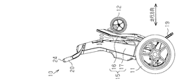
- the electric vehicle 10 includes a pair of driving wheels 11 and a driven wheel 12 that are arranged at intervals in the traveling direction.
- the pair of drive wheels 11 are provided at an interval in the vehicle width direction.
- the electric vehicle 10 includes a main body 15 having a deck 16 and a stay 17.
- the deck 16 constitutes a footrest portion or a luggage rest portion of a user who gets on.
- a first end portion of the deck 16 is connected to a lower end portion of the stay 17 so that the deck 16 can rotate around an axis O ⁇ b> 1 extending in the vehicle width direction with respect to the stay 17.
- the lower end portion of the stay 17 is widened on both sides in the vehicle width direction to form a pair of holder portions 17a.
- Both drive wheels 11 are arranged on both outer sides in the vehicle width direction of the lower end portion of the stay 17, that is, on the front end side of both holder portions 17 a, and are rotatable around an axis O 2 extending in the vehicle width direction at the lower end portion of the stay 17. It is supported.
- the driven wheel 12 is disposed below the deck 16.
- a bearing member 18 is provided at a second end portion of the deck 16 away from the stay 17, and the driven wheel 12 is rotatably supported by the bearing member 18.
- the bearing member 18 can rotate around an axis extending in the vertical direction with respect to the deck 16, and thus the deck 16 can be swiveled in the traveling direction.
- a loop-shaped handle 20 extending upward and on both sides in the vehicle width direction is supported so as to be rotatable around an axis extending in the vertical direction. That is, the handle 20 includes a connecting portion 21 into which the upper end of the stay 17 is fitted in a rotatable state, and a pair of handle portions 22 and 23 connected to both ends of the connecting portion 21 in the vehicle width direction. Both handle parts 22 and 23 have a substantially V shape, and extend away from the connecting part 21 in the vehicle width direction, and extend obliquely upward so as to approach each other. The tips of both grip portions 22 and 23 are connected to each other via a transport grip portion 24 extending in the vehicle width direction. The conveyance handle 24 is located at the center in the vehicle width direction of the part of the handle 20 on the side away from the stay 17.
- a substantially saddle-shaped seat 40 is connected to an intermediate portion in the vertical direction (longitudinal direction) of the stay 17 so as to be rotatable around an axis O3 extending in the vehicle width direction.
- a substantially disc-shaped mechanical first lock mechanism 31 as a lock member is disposed adjacent to the deck 16 on the holder portion 17a on one side (left side in FIG. 1).
- the first locking mechanism 31 is disposed coaxially with the axis O1, and is in a locked state that restricts the relative rotation of the deck 16 and the stay 17 around the axis O1, and the relative relationship between the deck 16 and the stay 17 around the axis O1. And an unlocked state allowing rotation.
- the first lock mechanism 31 is basically configured to maintain the locked state regardless of the angle formed by the deck 16 and the stay 17.
- the first lock mechanism 31 has a lock release actuator 32 as a lock release member.
- the unlocking actuator 32 includes, for example, an electric motor, and switches the first lock mechanism 31 to the unlocked state in response to the input of the drive signal. That is, the first lock mechanism 31 rotates the deck 16 and the stay 17 relative to each other. Release the restricted state.
- the unlock actuator 32 also allows the first lock mechanism 31 to be switched to the locked state in response to the stop of the input of the drive signal.
- Both holder parts 17a accommodate a pair of electric motors 33 that rotate and drive both drive wheels 11 around the axis O2. Further, a pair of electric or electromagnetic braking mechanisms 34 that reduce or stop the rotation of the electric motors 33 are accommodated in the holder portions 17a.
- the electric vehicle 10 can be driven straight along the traveling direction by the two electric motors 33 being rotationally driven together with the corresponding drive wheels 11 at the same rotational speed. For example, the electric vehicle 10 travels straight in the traveling direction in which the drive wheels 11 precede the driven wheels 12 (hereinafter also referred to as “forward traveling direction”) because the two electric motors 33 rotate forward at the same rotational speed. To do.
- the electric vehicle 10 has a traveling direction in which the drive wheels 11 follow the driven wheels 12 (hereinafter, also referred to as “reverse traveling direction”) by rotating both electric motors 33 at the same rotational speed. Go straight.
- the electric vehicle 10 can be turned by rotating both electric motors 33 together with the corresponding drive wheels 11 at different rotational speeds.
- the electric vehicle 10 can be decelerated or stopped by driving both braking mechanisms 34.
- a substantially disc-shaped mechanical second locking mechanism 41 is disposed adjacent to the seat 40 in the middle portion of the stay 17 in the vertical direction (longitudinal direction).
- the second lock mechanism 41 is disposed substantially coaxially with the axis O3, and is in a locked state that restricts relative rotation of the stay 17 and the seat 40 around the axis O3, and the stay 17 and the seat 40 around the axis O3. And an unlocked state allowing relative rotation.
- the second lock mechanism 41 is basically configured to maintain the locked state regardless of the angle formed by the seat 40 and the stay 17.
- a lock release lever 49 is connected to an intermediate portion in the vertical direction (longitudinal direction) of the stay 17 so as to be rotatable around the axis O3.
- the lock release lever 49 is formed in a substantially gate shape that sandwiches the seat 40 including the second lock mechanism 41 in the vehicle width direction, and is normally held at an initial position extending substantially along the stay 17.
- the lock release lever 49 is linked to the second lock mechanism 41.
- the electric vehicle 10 can be switched to various modes that realize postures according to the use by changing at least one angle of the deck 16 and the seat 40 with respect to the stay 17.
- FIG. 3 shows a seat riding mode (a sitting state or a boarding enabled state) which is one of the usage states of the electric vehicle 10.
- the “use state” means a state where the electric vehicle 10 is deployed so that it can be used by a user, that is, a state where the deck 16 and the stay 17 are open with respect to each other.
- the stay 17 is inclined so as to go in the reverse running direction as it goes upward, and the seat 40 extends substantially horizontally from the stay 17 in the reverse running direction.
- the rotation position of the sheet 40 at this time is referred to as a development position (or a fully open position).
- the user U In this seat riding mode, the user U is seated on the seat 40 in the forward running direction and grasps the handle 20, and takes the posture where the soles of both feet sandwiching the stay 17 in the vehicle width direction are on the deck 16. Thereby, the user U can move by electric power while sitting on the electric vehicle 10. It goes without saying that the stay 17 is positioned on the side preceding the deck 16 in the traveling direction (that is, the forward traveling direction) in the seat riding mode.
- FIG. 4 shows a cart mode (loading bed state) which is one of the usage states of the electric vehicle 10.
- the stay 17 is inclined so as to go in the reverse traveling direction as it goes upward, but the seat 40 extends downward substantially along the stay 17.
- the rotation position of the seat 40 at this time is referred to as a storage position (or a fully closed position).
- the user U takes a posture of standing in the reverse traveling direction and holding the handle 20 at a position ahead of the electric vehicle 10 in the forward traveling direction. As a result, the user U can move manually with the load B on the deck 16.
- the traveling direction in the cart mode (that is, the reverse traveling direction) is set to be opposite to the traveling direction in the seat riding mode (that is, the forward traveling direction).
- the electric motor 33 may be energized to drive both drive wheels 11. Thereby, when carrying a heavy load etc., the burden of the user U can be reduced.
- FIG. 5 shows a carry mode in which the electric vehicle 10 is folded.
- the electric vehicle 10 In the carry mode, the electric vehicle 10 is folded so that the deck 16 and the stay 17 overlap each other, and the seat 40 extends substantially along the stay 17 as in the cart mode.
- the user U grips the grip portion 24 at the time of conveyance in a state of being located on the opposite side of the deck 16 with respect to the stay 17. Thereby, the user U can carry the electric vehicle 10 while gripping the handle portion 24 at the time of conveyance and rolling the driving wheel 11.
- an arm-shaped stand 19 is connected to the first end of the deck 16, that is, the end on the side where the drive wheels 11 are located, so as to be rotatable around an axis extending in the vehicle width direction.
- the stand 19 supports the electric vehicle 10 in the carry mode in a standing posture in cooperation with the drive wheels 11 when the stand 19 is in a rotational position where the stand 16 is opened with respect to the deck 16 and can be brought into contact with the ground. Needless to say, the stand 19 is closed so that the tip does not contact the ground when the electric vehicle 10 is in use (seat riding mode or cart mode).
- the upper end portion of one handle portion 22 of the handle 20 is inserted into a cylindrical accelerator lever 26 that is substantially concentric with the handle portion 22.
- An accelerator lever 26 serving as an accelerator operation section is rotatable around its central axis and is held at a predetermined initial rotation position.
- the accelerator lever 26 is equipped with an electronic sensor having an acceleration sensing function, and is rotated by the user U from the initial rotation position, so that the movement speed (speed adjustment) according to the rotation angle.
- the operation signal (accelerator operation signal) is output.
- a push-type brake button 27 as a brake operation unit is provided at the upper end of the other handle portion 23 of the handle 20.
- the brake button 27 is equipped with an electronic switch having a braking sensing function, and is configured to output an operation signal (brake operation signal) for deceleration or stop when pressed by the user U. ing.
- a push-type selection switch 28 and a push-type trigger switch 29 are provided on the handle portion 24 of the handle 20 during conveyance.
- the selection switch 28 serving as a selection operation unit is arranged in the front part on the side where the handle part 22 is located in the handle part 24 during conveyance. This is because the user U standing in the reverse traveling direction at a position on the front side in the forward traveling direction with respect to the electric vehicle 10 in the cart mode can easily apply the thumb T of the right hand H to the selection switch 28. (See FIG. 1).
- the trigger switch 29 as the unlocking operation unit is disposed at the lower part of the center part in the vehicle width direction of the grip part 24 at the time of conveyance.
- the selection switch 28 and the push-type trigger switch 29 are disposed at different positions in the vehicle width direction, and are disposed at different positions in the circumferential direction of the grip portion 24 during conveyance.
- the selection switch 28 is operated to be pressed by the user U, and outputs an operation signal for selecting the type of usage (seat riding mode or the like). Specifically, the selection switch 28 sequentially advances the types of usage patterns in accordance with the number of operation signal outputs (that is, the number of pressing operations by the user U). Therefore, the operation signal (second operation signal) of the selection switch 28 also represents that the user U is in the boarding state or the non-boarding state.
- the trigger switch 29 outputs an operation signal indicating an intention to operate the unlocking actuator 32 so as to switch the first locking mechanism 31 to the unlocked state when pressed by the user U. More precisely, the simultaneous output of both operation signals from the selection switch 28 and the trigger switch 29 represents the intention to operate the unlocking actuator 32 to switch the first locking mechanism 31 to the unlocked state.
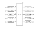
- the electric vehicle 10 includes an ECU (electronic control unit) 50 as a control unit installed at an appropriate location.
- the ECU 50 may include a microcomputer and / or dedicated hardware (an application specific integrated circuit: ASIC) that executes at least a part of various processes. That is, the ECU 50 includes 1) one or more processors (microcomputers) that operate according to a computer program (software), 2) one or more dedicated hardware circuits such as an ASIC, or 3) a combination thereof. It can be configured as a circuit.
- the ECU 50 is electrically connected to the accelerator lever 26 and inputs the aforementioned operation signal Ma of the accelerator lever 26.
- the ECU 50 is electrically connected to the brake button 27 and inputs the aforementioned operation signal Mb of the brake button 27. Further, the ECU 50 is electrically connected to the selection switch 28 and inputs the aforementioned operation signal Ms of the selection switch 28.
- the ECU 50 is electrically connected to the trigger switch 29 and inputs the aforementioned operation signal Mt of the trigger switch 29.
- the ECU 50 is electrically connected to a rotation operation amount sensor 56 installed at an appropriate location of the electric vehicle 10 (for example, the upper end portion of the stay 17).
- the rotation operation amount sensor 56 is an electronic sensor having a steering sensing function, and outputs a detection signal Mh representing the rotation operation amount of the handle 20 from a predetermined initial rotation position having a symmetrical attitude to the ECU 50. To do.
- the ECU 50 is electrically connected to both the electric motors 33 and individually controls the rotation direction and the rotation speed of the electric motors 33.
- the ECU 50 inputs the operation signal Ms from the selection switch 28, and determines the straight traveling direction corresponding to the forward movement and the reverse movement according to the type of usage pattern.
- the ECU 50 matches forward and reverse in the seat riding mode with the forward straight direction and the reverse straight direction, respectively.
- the ECU 50 matches the forward movement and the reverse movement in the cart mode with the reverse straight traveling direction and the forward straight traveling direction, respectively.
- the ECU 50 inputs the detection signal Mh from the rotation operation amount sensor 56 to determine the rotation ratio of both the electric motors 33. Specifically, the ECU 50 determines that the rotation ratio of both the electric motors 33 is 50:50 when the handle 20 is directed straight. When the steering wheel 20 is rotated in either the left or right direction, the ECU 50 determines whether the electric vehicle 10 is turned from the turning center in order to turn the electric vehicle 10 with a radius corresponding to the turning operation direction and the turning operation amount. The rotation ratio of both electric motors 33 is obtained so as to be proportional to the radius.
- the ECU 50 inputs the operation signal Ma from the accelerator lever 26 so that the ratio of the rotation speeds of the two electric motors 33 becomes the rotation ratio described above, and the average of both rotation speeds is the operation signal Ma from the accelerator lever 26.
- the rotational speeds of both electric motors 33 are determined so that the rotational speed is in accordance with the above.
- the ECU 50 rotates both the electric motors 33 together with the drive wheels 11 at the determined rotation speed. Needless to say, the rotational directions of the electric motors 33 and the like coincide with the moving direction of the electric vehicle 10 corresponding to forward or reverse in the usage pattern selected by the selection switch 28.
- the ECU 50 inputs the operation signal Ms from the selection switch 28 and the operation signal Mt from the trigger switch 29 at the same time, so as to basically switch the first lock mechanism 31 to the unlocked state,
- the drive signal described above is output.
- the unlocking actuator 32 switches the first lock mechanism 31 to the unlocked state, so that the electric vehicle 10 can be switched between the use state (seat riding mode or cart mode) and the carry mode. It becomes.
- the ECU 50 stops outputting the drive signal to the unlocking actuator 32 when at least one of the operation signal Ms from the selection switch 28 and the operation signal Mt from the trigger switch 29 is lost. Accordingly, the relative rotation between the deck 16 and the stay 17 is restricted regardless of the angle between the deck 16 and the stay 17.
- the user U when the electric vehicle 10 in the use state (seat riding mode or cart mode) is switched to the carry mode, the user U basically rotates the deck 16 and the stay 17 relative to each other until the folding of the electric vehicle 10 is completed.
- the selection switch 28 and the trigger switch 29 may be operated simultaneously by grasping the handle 20 (the handle portion 24 at the time of conveyance).
- the user U can fold the electric vehicle 10 while holding the handle 20 (the gripping part 24 at the time of transport) while bringing the deck 16 close to the stay 17.
- the user U can fold the electric vehicle 10 while bringing the stay 17 close to the deck 16. That is, the electric vehicle 10 may be standing or sleeping when the folding is completed.
- the user U when the electric vehicle 10 in the carry mode is switched to the use state (seat riding mode or cart mode), the user U similarly rotates the deck 16 and the stay 17 until the electric vehicle 10 is fully deployed.
- the selection switch 28 and the trigger switch 29 may be continuously operated by grasping the handle 20 (the grip part 24 at the time of conveyance). At this time, the user U can deploy the electric vehicle 10 while separating the stay 17 from the deck 16 while grasping the handle 20 (the grip part 24 at the time of conveyance).
- the user U can output the operation signal Mt and the like by operating the trigger switch 29 and the like while gripping the handle portion 24 at the time of conveyance of the handle 20.
- the ECU 50 outputs a drive signal to the unlock actuator 32, so that the restriction of the relative rotation by the first lock mechanism 31 is released.
- the user U holds the electric vehicle 10 between the use state (deployed state) and the folded state while relatively rotating the deck 16 and the stay 17 while supporting the stay 17 while holding the handle portion 24 during transportation. Can be switched.
- the user U operates the trigger switch 29 and switches the electric vehicle 10 between the use state (deployed state) and the folded state with a series of movements while holding the grip part 24 during transport. That is, it can be performed in one motion and the operability can be further improved.
- the output of the drive signal from the ECU 50 is executed when both operation signals Mt and Ms are output simultaneously. That is, the restriction of the relative rotation by the first lock mechanism 31 is released on the assumption that the user U is in a non-ride state. Therefore, the malfunction of the unlocking actuator 32 such that the restriction of the relative rotation by the first locking mechanism 31 is released while the user U is in the boarding state can be suppressed.
- the selection switch 28 and the trigger switch 29 are both installed in the transport handle 24 so that the user U can grasp the selection switch 28 and the trigger switch while holding the transport handle 24. 29 can be easily operated simultaneously in one motion, and the operability can be further improved while suppressing malfunction of the unlocking actuator 32.
- the accelerator lever 26 related to the movement speed operation (acceleration function) and the brake button 27 related to the deceleration or stop operation (forced brake function) are Installed on both sides in the vehicle width direction.
- the user U can share the operation of the accelerator lever 26 and the operation of the brake button 27 with the left and right hands holding the handle 20 (the grip portions 22 and 23). For this reason, the user U can be aware of both operations without releasing his hand from the handle 20, and can easily operate without making a mistake.
- the user U does not need to release his / her hand from the handle 20 at the time of speed adjustment or the like, that is, the user 20 can always hold the handle 20 with both hands, thereby further improving the operation stability of the vehicle.
- a single lever completes an operation related to traveling (“run”, “turn”, “stop”), such as a joystick, for example, S-shaped travel in a narrow path with obstacles
- traveling travel
- stop a joystick
- each operation of “run”, “bend”, and “stop” is shared by the handle 20 and the accelerator lever 26 and the brake button 27 that are integrated with the handle 20.
- the person U can easily understand the necessary operations and instructions intuitively.
- the steering angle instruction is realized by a turning operation from the initial turning position of the handle 20, an operation that matches the intended behavior of the electric vehicle 10 is possible.
- both the operability and the operational safety based on proper judgment of the state of the user U and the electric vehicle 10 can be realized by controlling the unlocking actuator 32 by the ECU 50.
- the lock can be released smoothly by the electric drive of the lock release actuator 32.
- the relative rotation of the deck 16 and the stay 17 when the electric vehicle 10 is switched between the use state (deployed state) and the carry mode is manually performed by the user U.
- the switching speed can be determined independently by the user U. Therefore, switching between the use state (deployed state) and the carry mode of the electric vehicle 10 can be performed at a speed suitable for the sense of the user U, and convenience can be improved.
- the transport handle portion 24 gripped by the user U when transporting the electric vehicle 10 in the carry mode is disposed at the center portion in the vehicle width direction of the handle 20, and for example, a seat ride It is continuous and integrated with both grip portions 23 gripped by the user U who rides on the electric vehicle 10 in the mode.
- the selection switch 28 and the trigger switch 29 provided in the grip part 24 at the time of conveyance see the electric vehicle 10 in the front (stand toward the reverse traveling direction at a position on the preceding side in the forward traveling direction than the electric vehicle 10).
- the thumb T of the right hand H of the user U and the other fingers F are arranged at portions that can be pressed or are easily pressed.
- the selection switch 28 and the trigger switch 29 are arranged at positions where the user can easily operate the switches 28 and 29 at the same time in a state where the user grips the handle portion 24 at the time of transportation of the electric vehicle 10 in the folded state. . Therefore, the user U can operate the selection switch 28 and the trigger switch 29 simultaneously without basically changing the way of gripping the handle 20. For this reason, for example, when the electric vehicle 10 is switched to the carry mode, the selection switch 28 and the trigger switch 29 are operated simultaneously (unlock instruction to the first lock mechanism 31) ⁇ the operation of the unlock actuator 32 (the lock of the first lock mechanism 31).
- the operation of lowering the stay 17 or raising the deck 16 when the electric vehicle 10 is folded can be further stabilized, and the stay 17 is always supported by the user's hand holding the handle portion 24 at the time of conveyance.
- the electric vehicle 10 can be held lightly.
- the handle 20 easily swings. Basically, the user U moves the handle portion 24, that is, the handle 20.
- the holding of the electric vehicle 10 during folding or subsequent conveyance can be further stabilized.
- the selection switch 28 and the trigger switch 29 are arranged so as to be very difficult to press even if the user U who is on the seat 40 tries to operate. That is, the selection switch 28 and the trigger switch 29 are arranged at positions where it is difficult to operate the switches 28 and 29 in a state where the user gets on the electric vehicle 10 in a state where the user can ride. Therefore, the possibility that the first lock mechanism 31 is released due to an erroneous operation can be reduced.
- the electric vehicle 10 can be made compact by switching to the carry mode when the electric vehicle 10 is conveyed.
- the ECU 50 stops the output of the operation signal Mt or the like while outputting the drive signal to the unlocking actuator 32, that is, when the operation of the trigger switch 29 or the like is stopped for some reason. The drive signal output is stopped. Accordingly, the relative rotation of the deck 16 and the stay 17 can be quickly controlled by the first lock mechanism 31 in accordance with the cancellation of the intention to cancel the control of the relative rotation of the deck 16 and the stay 17.
- the relative rotation between the deck 16 and the stay 17 is quickly performed by the first lock mechanism 31.
- the first lock mechanism 31 it is possible to prevent the stay 17 and the like from falling while the electric vehicle 10 is switched to the carry mode.
- the standing mode as in the cart mode, the stay 17 is inclined so as to go in the reverse traveling direction as it goes upward, and the seat 40 extends downward substantially along the stay 17.
- the user U holds the handle 20 in the forward running direction, puts one foot on the ground, and puts the opposite foot on the deck 16. Thereby, the user U can move by human power while kicking the ground with one foot.
- the rotation of the bearing member 18 around the axis extending in the vertical direction can be fixed manually or electrically so that the axis of the driven wheel 12 is fixed in a state extending in the vehicle width direction. It is preferable to provide an appropriate locking mechanism.
- the drive wheel 11 may be rotatably supported by the deck 16.
- a pair of driven wheel 12 may be provided at intervals in the vehicle width direction.
- the braking mechanism 34 may be built in the electric motor 33.
- the arrangement of the accelerator lever 26 and the brake button 27 on the handle 20 is arbitrary.
- the accelerator lever 26 and the brake button 27 may be collectively arranged on one side of the handle 20 in the vehicle width direction.
- At least one of the accelerator lever 26 and the brake button 27 may be disposed at an appropriate position of the electric vehicle 10 other than the handle 20.
- an instruction for the movement speed (speed adjustment) may be given by a speed input device such as a joystick installed at an appropriate position of the handle 20, for example.
- a speed input device such as a joystick installed at an appropriate position of the handle 20, for example.
- the selection switch 28 may be disposed at an appropriate position of the handle 20 other than the handle part 24 at the time of conveyance, or may be disposed at an appropriate position of the electric vehicle 10 other than the handle 20.
- the unlocking actuator 32 may be operated only by operating the trigger switch 29.
- the handle 20 may be fixed to the stay 17 so as not to rotate.
- the steering angle may be instructed by a direction input device such as a joystick installed at an appropriate position of the handle 20, for example.
- the first lock mechanism 31 allows the relative rotation of the deck 16 and the stay 17 only when the angle formed between the deck 16 and the stay 17 matches the angle corresponding to the fully opened state and the fully closed state. It may be configured to restrict movement.
- the selection switch 28 is used to select the type of usage of the electric vehicle 10 (seat riding mode, etc.) in the form of forward feeding according to the number of pressing operations. In this case, it is preferable to provide an appropriate notification device (such as a light emitting member or a utterance member) that notifies the user U of the type of usage of the electric vehicle 10 being selected.
- the selection switch 28 may be a switch that can individually select the mode of the electric vehicle 10.
- the ECU 50 controls all functions of the electric vehicle 10, but the functions may be controlled by a plurality of control devices. At this time, in the case where linkage is required between a plurality of control devices, a master-slave relationship may be defined between the control devices.
Landscapes
- Engineering & Computer Science (AREA)
- Mechanical Engineering (AREA)
- Motorcycle And Bicycle Frame (AREA)
- Automatic Cycles, And Cycles In General (AREA)
- Electric Propulsion And Braking For Vehicles (AREA)
Abstract
電動車は、デッキ及び該デッキに回動自在に連結されたステイを有する本体部と、ステイに支持され、搬送時把手部を有するループ状のハンドルと、デッキ及びステイの相対回動を規制するロック部材と、電動車を使用状態と折り畳み状態との間で切り替えることが可能になるようにロック部材による相対回動の規制を解除するロック解除部材と、搬送時把手部に設置され、前記相対回動の規制を解除する意思を表す操作信号を出力するロック解除操作部と、操作信号が出力されたとき、前記相対回動の規制を解除させる駆動信号をロック解除部材に出力する制御部と、を備える。
Description
本発明は、電動車に関するものである。
例えば特許文献1に記載された電動車が知られている。この電動車は、走行方向に間隔をあけて配置された駆動輪及び従動輪と、荷物置き部を有して駆動輪及び従動輪間に配置されそれら駆動輪及び従動輪を回転可能に支持するデッキ(フレーム)と、デッキに連結されて該デッキから上方に延びるステイと、ステイに支持されたシート及びハンドルとを備える。そして、電動車は、利用者がシートに着座してハンドルを握る座り乗り状態と、利用者がシートから地面に降りてハンドルを握る荷台状態との間で使用状態を切替可能に構成されている。
ステイは、デッキに回動自在に連結されており、電動車の運搬時にはステイ及びデッキが重なるように閉じられる(折り畳み状態)。これにより、電動車の円滑な運搬が可能となる。
上記特許文献1では、例えば電動車を座り乗り状態等の使用状態と折り畳み状態との間で切り替えるための操作について何ら言及されていないものの、その切り替えに際して優れた操作性が求められることは疑いの余地はない。
本発明の目的は、使用状態と折り畳み状態との間で切り替える際の操作性をより向上できる電動車を提供することにある。
上記課題を解決する電動車は、デッキ及び該デッキに回動自在に連結されたステイを有し、駆動輪及び従動輪を支持する本体部と、前記ステイに支持され、搬送時把手部を有するループ状のハンドルであって、前記搬送時把手部は、前記ハンドルにおいて、前記ステイから離間する側の部位の車幅方向中央部に位置する、ハンドルと、前記デッキ及び前記ステイの相対回動を規制するように構成されたロック部材と、前記電動車を使用状態と折り畳み状態との間で切り替えることが可能になるように前記ロック部材による前記相対回動の規制を解除するように構成されたロック解除部材と、前記搬送時把手部に設置され、前記相対回動の規制を解除する意思を表す操作信号を出力するように構成されたロック解除操作部と、前記操作信号が出力されたとき、前記相対回動の規制を解除させる駆動信号を前記ロック解除部材に出力するように構成された制御部と、を備える。
以下、電動車の一実施形態について説明する。
図1及び図2に示すように、電動車10は、走行方向に間隔をあけて配置された一対の駆動輪11と従動輪12とを備える。一対の駆動輪11は、車幅方向に間隔をあけて設けられている。また、電動車10は、デッキ16及びステイ17を有する本体部15を備える。デッキ16は、乗車する利用者の足載せ部、若しくは荷物載せ部を構成している。デッキ16がステイ17に対して車幅方向に延びる軸線O1の周りに回動自在となるように、デッキ16の第1端部がステイ17の下端部に連結されている。ステイ17の下端部は、車幅方向両側に拡幅されて一対のホルダ部17aを形成する。
図1及び図2に示すように、電動車10は、走行方向に間隔をあけて配置された一対の駆動輪11と従動輪12とを備える。一対の駆動輪11は、車幅方向に間隔をあけて設けられている。また、電動車10は、デッキ16及びステイ17を有する本体部15を備える。デッキ16は、乗車する利用者の足載せ部、若しくは荷物載せ部を構成している。デッキ16がステイ17に対して車幅方向に延びる軸線O1の周りに回動自在となるように、デッキ16の第1端部がステイ17の下端部に連結されている。ステイ17の下端部は、車幅方向両側に拡幅されて一対のホルダ部17aを形成する。
両駆動輪11は、ステイ17の下端部の車幅方向両外側、すなわち両ホルダ部17aの先端側に配置され、該ステイ17の下端部に車幅方向に延びる軸線O2の周りに回転可能に支持されている。従動輪12は、デッキ16の下方に配置されている。デッキ16におけるステイ17から離間した第2端部には軸受部材18が設けられ、この軸受部材18に従動輪12が回転可能に支持されている。軸受部材18はデッキ16に対し上下方向に延びる軸線の周りに回転可能であり、これにより、デッキ16は走行方向に対し旋回可能である。
ステイ17の上端には、上方及び車幅方向両側に広がるループ状のハンドル20が上下方向に延びる軸線の周りに回動自在に支持されている。すなわち、ハンドル20は、回動自在な状態でステイ17の上端が嵌挿される連結部21を有するとともに、該連結部21の車幅方向両端に接続される一対の把手部22,23を有する。両把手部22,23は略V字形状を有し、車幅方向において、連結部21から互いに離れるように延び、そして互いに近づくように斜め上方に延びている。両把手部22,23の先端同士は、車幅方向に延在する搬送時把手部24を介して接続されている。搬送時把手部24は、ハンドル20において、ステイ17から離間する側の部位の車幅方向中央部に位置する。
ステイ17の上下方向(長手方向)における中間部には、略サドル状のシート40が車幅方向に延びる軸線O3の周りに回動自在に連結されている。
片側(図1において左側)のホルダ部17aには、ロック部材としての略円盤状の機械式の第1ロック機構31がデッキ16に隣接して配置されている。この第1ロック機構31は軸線O1と同軸に配置され、軸線O1の周りでのデッキ16及びステイ17の相対回動を規制するロック状態と、軸線O1の周りでのデッキ16及びステイ17の相対回動を許容するロック解除状態とを有する。第1ロック機構31は、デッキ16とステイ17とがなす角度に関わらず、基本的にロック状態を保持するように構成されている。
片側(図1において左側)のホルダ部17aには、ロック部材としての略円盤状の機械式の第1ロック機構31がデッキ16に隣接して配置されている。この第1ロック機構31は軸線O1と同軸に配置され、軸線O1の周りでのデッキ16及びステイ17の相対回動を規制するロック状態と、軸線O1の周りでのデッキ16及びステイ17の相対回動を許容するロック解除状態とを有する。第1ロック機構31は、デッキ16とステイ17とがなす角度に関わらず、基本的にロック状態を保持するように構成されている。
第1ロック機構31は、ロック解除部材としてのロック解除アクチュエータ32を有する。このロック解除アクチュエータ32は例えば電動モータを含み、駆動信号の入力に応答して第1ロック機構31をロック解除状態に切り替える、すなわち、第1ロック機構31がデッキ16及びステイ17の相対回動を規制した状態を解除する。ロック解除アクチュエータ32はまた、駆動信号の入力の停止に応答して、第1ロック機構31のロック状態への切り替わりを許容する。
両ホルダ部17aには、軸線O2の周りに両駆動輪11をそれぞれ回転駆動する一対の電動モータ33が収容されている。さらに、両ホルダ部17aには、両電動モータ33の回転をそれぞれ減速又は停止させる一対の電気式又は電磁式のブレーキング機構34が収容されている。電動車10は、両電動モータ33が対応する駆動輪11と共に互いに同一の回転速度で回転駆動されることで、走行方向に沿って直進可能である。例えば電動車10は、両電動モータ33が互いに同一の回転速度で正転することで、駆動輪11が従動輪12に対して先行する走行方向(以下、「順走行方向」ともいう)に直進する。反対に、電動車10は、両電動モータ33が互いに同一の回転速度で逆転することで、駆動輪11が従動輪12に対して追従する走行方向(以下、「逆走行方向」ともいう)に直進する。また、電動車10は、両電動モータ33が対応する駆動輪11と共に互いに異なる回転速度で回転駆動されることで、旋回走行可能である。さらに、電動車10は、両ブレーキング機構34が駆動されることで減速又は停止可能である。
ステイ17の上下方向(長手方向)における中間部には、略円盤状の機械式の第2ロック機構41がシート40に隣接して配置されている。この第2ロック機構41は軸線O3と略同軸に配置され、軸線O3の周りでのステイ17及びシート40の相対回動を規制するロック状態と、軸線O3の周りでのステイ17及びシート40の相対回動を許容するロック解除状態とを有する。第2ロック機構41は、シート40とステイ17とがなす角度に関わらず、基本的にロック状態を保持するように構成されている。
また、ステイ17の上下方向(長手方向)における中間部には、ロック解除レバー49が軸線O3の周りに回動自在に連結されている。このロック解除レバー49は、第2ロック機構41を含むシート40を車幅方向に挟む略門型に形成されており、通常はステイ17に略沿って上方に延びる初期位置に保持されている。ロック解除レバー49は、第2ロック機構41に連係されており、ステイ17から離れるように初期位置から回動操作されることで第2ロック機構41をロック解除状態に切り替えるとともに、回動操作の解放に伴い初期位置に復帰回動することで第2ロック機構41のロック状態への切り替わりを許容する。
電動車10は、ステイ17に対して、デッキ16及びシート40の少なくとも一つの角度を変更することで、その用途に合わせた姿勢を実現する各種モードへの切替えが可能である。
図3は、電動車10の使用状態の一つであるシート乗車モード(座り乗り状態或いは搭乗可能状態)を示す。なお、「使用状態」とは、電動車10が利用者によって使用可能なように展開された状態、すなわちデッキ16及びステイ17が互いに対して開いた状態を意味する。シート乗車モードでは、ステイ17が上方に向かうに従い逆走行方向に向かうように傾斜しており、シート40がステイ17から逆走行方向に向かって略水平に延びている。このときのシート40の回動位置を展開位置(又は全開位置)という。このシート乗車モードでは、利用者Uは、順走行方向に向いてシート40に着座しハンドル20を握るとともに、ステイ17を車幅方向に挟んだ両足の足裏をデッキ16においた姿勢を取る。これにより、利用者Uは、電動車10に座り乗りする状態で電動での移動が可能となる。ステイ17がシート乗車モードにおける走行方向(すなわち、順走行方向)においてデッキ16に対し先行する側に位置していることはいうまでもない。
図4は、電動車10の使用状態の一つであるカートモード(荷台状態)を示す。このカートモードでは、シート乗車モードと同様にステイ17が上方に向かうに従い逆走行方向に向かうように傾斜しているが、シート40はステイ17に略沿って下方に向かって延びている。このときのシート40の回動位置を格納位置(又は全閉位置)という。このカートモードでは、利用者Uは、電動車10よりも順走行方向における先行側の位置で逆走行方向に向いて立ってハンドル20を握る姿勢を取る。これにより、利用者Uは、デッキ16に荷物Bを載せた状態で人力での移動が可能となる。カートモードにおける走行方向(すなわち、逆走行方向)が、シート乗車モードにおける走行方向(すなわち、順走行方向)とは逆向きに設定されていることはいうまでもない。また、カートモードにおいて、電動モータ33を通電させて両駆動輪11を駆動させてもよい。これにより、重い荷物等を運ぶときには、利用者Uの負担を軽減することができる。
図5は、電動車10の折り畳み状態であるキャリーモードを示す。このキャリーモードでは、デッキ16及びステイ17が重なるように電動車10が折り畳まれており、カートモードと同様にシート40がステイ17に略沿って延びている。利用者Uは、ステイ17に対してデッキ16とは反対側に位置する状態で搬送時把手部24を掴む。これにより、利用者Uは、搬送時把手部24を掴んで駆動輪11を転動させつつ電動車10を運搬することが可能となる。
デッキ16の第1端部、すなわち駆動輪11が位置する側の端部には、例えばアーム状のスタンド19が車幅方向に延びる軸線の周りに回動自在に連結されている。このスタンド19は、デッキ16に対して開いてその先端が地面に接触可能な回動位置にあるときに、両駆動輪11と協働してキャリーモードにある電動車10を起立姿勢で支える。電動車10の使用状態(シート乗車モード又はカートモード)では、先端が地面に接触しないようにスタンド19を閉じておくことはいうまでもない。
図1に示すように、ハンドル20の一方の把手部22の上端部は、把手部22と略同心の筒状のアクセルレバー26に挿通されている。アクセル操作部としてのアクセルレバー26は、その中心軸線周りに回動自在であるとともに、所定の初期回動位置に保持されている。アクセルレバー26は、アクセレーション感知機能を有する電子センサを搭載しており、利用者Uにより初期回動位置から回動操作されることで、その回動角度に応じて移動速度(速度調整)についての操作信号(アクセル操作信号)を出力するように構成されている。一方、ハンドル20のもう一方の把手部23の上端部には、ブレーキ操作部としての押下式のブレーキボタン27が設置されている。このブレーキボタン27は、ブレーキング感知機能を有する電子スイッチを搭載しており、利用者Uにより押下操作されることで、減速若しくは停止についての操作信号(ブレーキ操作信号)を出力するように構成されている。
ハンドル20の搬送時把手部24には、押下式の選択スイッチ28及び押下式のトリガースイッチ29が設置されている。選択操作部としての選択スイッチ28は、搬送時把手部24において、把手部22が位置する側の前部に配置されている。これは、カートモードにおいて電動車10よりも順走行方向における先行側の位置で逆走行方向に向いて立つ利用者Uが、右手Hの親指Tを選択スイッチ28に無理なく当てられるようにするためである(図1参照)。ロック解除操作部としてのトリガースイッチ29は、搬送時把手部24における車幅方向中央部の下部に配置されている。これは、同じく電動車10よりも順走行方向における先行側の位置で逆走行方向に向いて立つ利用者Uが、右手Hの親指T以外の指Fで搬送時把手部24を握る際に指Fをトリガースイッチ29に無理なく当てられるようにするためである(図1参照)。あるいは、シート乗車モードにおいて順走行方向に向いてシート40に着座してハンドル20を握る利用者Uが、指F等をトリガースイッチ29に容易に当てられないようにするためである。選択スイッチ28及び押下式のトリガースイッチ29は、車幅方向において互いに異なる位置に配置されるとともに、搬送時把手部24の周方向において互いに異なる位置に配置されている。
選択スイッチ28は、利用者Uにより押下操作されることで、使用形態の種類(シート乗車モード等)の選択についての操作信号を出力する。具体的には、選択スイッチ28は、操作信号の出力回数(即ち利用者Uによる押下操作の回数)に応じて使用形態の種類を順送りする。従って、選択スイッチ28の操作信号(第2の操作信号)は、利用者Uが乗車状態及び非乗車状態のいずれかであることを表すものでもある。
一方、トリガースイッチ29は、利用者Uにより押下操作されることで、第1ロック機構31をロック解除状態に切り替えるべくロック解除アクチュエータ32を作動させる意思を表す操作信号を出力する。より厳密には、選択スイッチ28及びトリガースイッチ29からの両操作信号の同時出力が、第1ロック機構31をロック解除状態に切り替えるべくロック解除アクチュエータ32を作動させる意思を表すようになっている。
次に、電動車10の電気的構成について説明する。
図6に示すように、電動車10は、その適宜箇所に設置された制御部としてのECU(電子制御装置)50を備える。ECU50は、マイクロコンピュータ、及び/又は、各種処理のうち少なくとも一部の処理を実行する専用のハードウェア(特定用途向け集積回路:ASIC)を備えたものであってもよい。すなわち、ECU50は、1)コンピュータプログラム(ソフトウェア)に従って動作する1つ以上のプロセッサ(マイクロコンピュータ)、2)ASIC等の1つ以上の専用のハードウェア回路、或いは、3)それらの組み合わせ、を含む回路として構成することができる。
図6に示すように、電動車10は、その適宜箇所に設置された制御部としてのECU(電子制御装置)50を備える。ECU50は、マイクロコンピュータ、及び/又は、各種処理のうち少なくとも一部の処理を実行する専用のハードウェア(特定用途向け集積回路:ASIC)を備えたものであってもよい。すなわち、ECU50は、1)コンピュータプログラム(ソフトウェア)に従って動作する1つ以上のプロセッサ(マイクロコンピュータ)、2)ASIC等の1つ以上の専用のハードウェア回路、或いは、3)それらの組み合わせ、を含む回路として構成することができる。
ECU50は、アクセルレバー26に電気的に接続されており、該アクセルレバー26の前述の操作信号Maを入力する。また、ECU50は、ブレーキボタン27に電気的に接続されており、該ブレーキボタン27の前述の操作信号Mbを入力する。さらに、ECU50は、選択スイッチ28に電気的に接続されており、該選択スイッチ28の前述の操作信号Msを入力する。また、ECU50は、トリガースイッチ29に電気的に接続されており、該トリガースイッチ29の前述の操作信号Mtを入力する。
さらに、ECU50は、電動車10の適宜箇所(例えばステイ17の上端部)に設置された回動操作量センサ56に電気的に接続されている。この回動操作量センサ56は、ステアリング感知機能を有する電子センサであって、左右対称な姿勢である所定の初期回動位置からのハンドル20の回動操作量を表す検出信号MhをECU50に出力する。
また、ECU50は、両電動モータ33に電気的に接続されており、それら電動モータ33の回転方向及び回転速度を個別に制御する。
すなわち、ECU50は、選択スイッチ28からの操作信号Msを入力することで、使用形態の種類に応じて、前進及び後進に対応する直進方向を決定する。具体的には、ECU50は、例えばシート乗車モードにおける前進及び後進をそれぞれ順直進方向及び逆直進方向に一致させる。あるいは、ECU50は、カートモードにおける前進及び後進をそれぞれ逆直進方向及び順直進方向に一致させる。
すなわち、ECU50は、選択スイッチ28からの操作信号Msを入力することで、使用形態の種類に応じて、前進及び後進に対応する直進方向を決定する。具体的には、ECU50は、例えばシート乗車モードにおける前進及び後進をそれぞれ順直進方向及び逆直進方向に一致させる。あるいは、ECU50は、カートモードにおける前進及び後進をそれぞれ逆直進方向及び順直進方向に一致させる。
さらに、ECU50は、回動操作量センサ56からの検出信号Mhを入力することで、両電動モータ33の回転比率を決定する。具体的には、ECU50は、ハンドル20が直進方向を向いている場合には、両電動モータ33の回転比率を50:50と決定する。ECU50は、ハンドル20が左右のいずれかの方向に回動操作されている場合には、その回動操作方向及び回動操作量に応じた半径で電動車10を旋回させるべく、旋回中心からの半径に比例するように両電動モータ33の回転比率を求める。
また、ECU50は、アクセルレバー26からの操作信号Maを入力することで、両電動モータ33の回転速度の比率が前述の回転比率となるとともに両回転速度の平均がアクセルレバー26からの操作信号Maに応じた回転速度となるように両電動モータ33の回転速度をそれぞれ決定する。そして、ECU50は、その決定した回転速度で両電動モータ33を駆動輪11と共に回転させる。両電動モータ33等の回転方向が、選択スイッチ28で選択した使用形態における前進又は後進に対応する電動車10の移動方向に合致することはいうまでもない。
特に、ECU50は、選択スイッチ28からの操作信号Ms及びトリガースイッチ29からの操作信号Mtを同時に入力することで、基本的に第1ロック機構31をロック解除状態に切り替えるべく、ロック解除アクチュエータ32に前述の駆動信号を出力する。この駆動信号に応答してロック解除アクチュエータ32が第1ロック機構31をロック解除状態に切り替えることで、電動車10を使用状態(シート乗車モード又はカートモード)及びキャリーモードの間で切り替えることが可能となる。あるいは、ECU50は、選択スイッチ28からの操作信号Ms及びトリガースイッチ29からの操作信号Mtの少なくとも一つの入力がなくなることで、ロック解除アクチュエータ32への駆動信号の出力を停止する。これにより、デッキ16がステイ17との間になす角度に関わらず、デッキ16とステイ17との相対回動が規制される。
従って、使用状態(シート乗車モード又はカートモード)にある電動車10をキャリーモードに切り替える際、基本的に利用者Uは、電動車10の折り畳みが完了するまでデッキ16及びステイ17の相対回動を許容すべく、ハンドル20(搬送時把手部24)を握って選択スイッチ28及びトリガースイッチ29を同時操作し続ければよい。このとき、利用者Uは、ハンドル20(搬送時把手部24)を握りながらデッキ16をステイ17に近付けつつ電動車10を折り畳むことが可能である。あるいは、利用者Uは、デッキ16にステイ17を近付けつつ電動車10を折り畳むことが可能である。つまり、折り畳みが完了した段階で電動車10は立っていてもよいし、寝ていてもよい。
一方、例えば利用者Uの右手Hが何らかの事情でハンドル20(搬送時把手部24)から離れたり握りが緩んだりすると、電動車10の折り畳みが未完了であってもデッキ16及びステイ17の相対回動が速やかに規制される。
また、キャリーモードにある電動車10を使用状態(シート乗車モード又はカートモード)に切り替える際、利用者Uは、同様に電動車10の展開が完了するまでデッキ16及びステイ17の相対回動を許容すべく、ハンドル20(搬送時把手部24)を握って選択スイッチ28及びトリガースイッチ29を同時操作し続ければよい。このとき、利用者Uは、ハンドル20(搬送時把手部24)を握りながらデッキ16からステイ17を離しつつ電動車10を展開することが可能である。
一方、例えば利用者Uの右手Hが何らかの事情でハンドル20(搬送時把手部24)から離れたり握りが緩んだりすると、電動車10の展開が未完了であってもデッキ16及びステイ17の相対回動が速やかに規制される。
次に、本実施形態の作用とともに、その効果について説明する。
(1)本実施形態では、利用者Uは、ハンドル20の搬送時把手部24を握りながらトリガースイッチ29等を操作することで、操作信号Mt等を出力させることができる。それに応答して、ECU50が駆動信号をロック解除アクチュエータ32に出力することで、第1ロック機構31による前記相対回動の規制が解除される。これにより、利用者Uは、搬送時把手部24を握った状態でステイ17を支えながらデッキ16及びステイ17を相対回動させつつ電動車10を使用状態(展開状態)と折り畳み状態との間で切り替えることができる。このように、利用者Uは、搬送時把手部24を握ったまま、トリガースイッチ29の操作、及び使用状態(展開状態)と折り畳み状態との間での電動車10の切り替えを一連の動きですなわち1モーションで行うことができ、操作性をより向上できる。
(1)本実施形態では、利用者Uは、ハンドル20の搬送時把手部24を握りながらトリガースイッチ29等を操作することで、操作信号Mt等を出力させることができる。それに応答して、ECU50が駆動信号をロック解除アクチュエータ32に出力することで、第1ロック機構31による前記相対回動の規制が解除される。これにより、利用者Uは、搬送時把手部24を握った状態でステイ17を支えながらデッキ16及びステイ17を相対回動させつつ電動車10を使用状態(展開状態)と折り畳み状態との間で切り替えることができる。このように、利用者Uは、搬送時把手部24を握ったまま、トリガースイッチ29の操作、及び使用状態(展開状態)と折り畳み状態との間での電動車10の切り替えを一連の動きですなわち1モーションで行うことができ、操作性をより向上できる。
(2)本実施形態では、ECU50からの駆動信号の出力は、両操作信号Mt,Msが同時に出力されたときに実行される。つまり、利用者Uが非乗車状態にあることを前提に、第1ロック機構31による前記相対回動の規制が解除される。従って、利用者Uが乗車状態のまま第1ロック機構31による前記相対回動の規制が解除されるといったロック解除アクチュエータ32の誤作動を抑制できる。
(3)本実施形態では、選択スイッチ28及びトリガースイッチ29が共に搬送時把手部24に設置されることで、利用者Uは、搬送時把手部24を握った状態で選択スイッチ28及びトリガースイッチ29を容易に1モーションで同時操作でき、ロック解除アクチュエータ32の誤作動を抑制しながらも操作性をより向上できる。
(4)本実施形態では、移動速度の操作(アクセレーション機能)に係るアクセルレバー26と減速又は停止の操作(強制ブレーキ機能)に係るブレーキボタン27とが、ハンドル20において搬送時把手部24の車幅方向両側にそれぞれ設置される。これにより、利用者Uは、ハンドル20(把手部22,23)を握る左右の手でアクセルレバー26の操作とブレーキボタン27の操作とを分担できる。このため、利用者Uは、ハンドル20から手を離すことなく両操作を意識でき、間違うことなく容易に操作できる。
また、利用者Uは、速度調整等の際にハンドル20から手を離す必要がないことで、即ち常に両手でハンドル20を保持できることで、車両の操作安定性をより向上できる。
(5)例えばジョイスティックなどのように、走行(「走る」、「曲がる」、「止まる」)に係る操作を一つのレバーで完結させる場合、例えば狭く障害物の存在する通路におけるS字走行のように瞬時に加減速と操舵とが求められる状況において、所要の速度及び操舵角度を指示することが非常に困難であった。これは、速度及び操舵角度の指示が当該レバーの位置(座標値)での指示になるため、利用者Uが直感的に理解して指示することが困難なためである。これに対し、本実施形態では、「走る」、「曲がる」、「止まる」の各操作がハンドル20並びにこれに一体化されたアクセルレバー26及びブレーキボタン27の各々に分担されることで、利用者Uは、必要な操作及び指示を直感的に理解して容易に実行できる。特に、操舵角度の指示を、ハンドル20の初期回動位置からの回動操作によって実現したことで、意図する電動車10の挙動に合致する操作が可能である。
(5)例えばジョイスティックなどのように、走行(「走る」、「曲がる」、「止まる」)に係る操作を一つのレバーで完結させる場合、例えば狭く障害物の存在する通路におけるS字走行のように瞬時に加減速と操舵とが求められる状況において、所要の速度及び操舵角度を指示することが非常に困難であった。これは、速度及び操舵角度の指示が当該レバーの位置(座標値)での指示になるため、利用者Uが直感的に理解して指示することが困難なためである。これに対し、本実施形態では、「走る」、「曲がる」、「止まる」の各操作がハンドル20並びにこれに一体化されたアクセルレバー26及びブレーキボタン27の各々に分担されることで、利用者Uは、必要な操作及び指示を直感的に理解して容易に実行できる。特に、操舵角度の指示を、ハンドル20の初期回動位置からの回動操作によって実現したことで、意図する電動車10の挙動に合致する操作が可能である。
(6)本実施形態では、ECU50によりロック解除アクチュエータ32を駆動制御することで、利用者Uや電動車10の状態の適正な判断に基づく操作性と操作安全性との両立を実現できる。あるいは、仮に電動車10の状態によって第1ロック機構31のロック解除に要する操作力が過大になったとしても、ロック解除アクチュエータ32の電動駆動によって円滑にロック解除できる。
(7)本実施形態では、電動車10を使用状態(展開状態)及びキャリーモードの間で切り替える際のデッキ16及びステイ17の相対回動が利用者Uによる手動操作で行われることで、例えばその切替速度を利用者Uによって主体的に決めることができる。従って、電動車10の使用状態(展開状態)及びキャリーモードの間の切り替えを利用者Uの感覚に適した速度で行うことができ、利便性を高めることができる。
(8)本実施形態では、キャリーモードにある電動車10を搬送する際に利用者Uが握る搬送時把手部24は、ハンドル20の車幅方向中央部に配置されているとともに、例えばシート乗車モードにある電動車10に搭乗する利用者Uが握る両把手部23と連続し且つ一体化されている。そして、搬送時把手部24に設けられた選択スイッチ28及びトリガースイッチ29は、電動車10を正面に見る(電動車10よりも順走行方向における先行側の位置で逆走行方向に向いて立つ)利用者Uの右手Hの親指T及びそれ以外の指Fがそれぞれ押下可能な若しくは押下し易い部位に配置されている。すなわち、選択スイッチ28及びトリガースイッチ29は、利用者が折り畳み状態にある電動車10の搬送時把手部24を手で握った状態で両スイッチ28,29を同時に操作し易い位置に配置されている。従って、利用者Uは、基本的にハンドル20の握り方を変えることなく選択スイッチ28及びトリガースイッチ29の同時操作が可能である。このため、例えば電動車10をキャリーモードに切り替える際、選択スイッチ28及びトリガースイッチ29の同時操作(第1ロック機構31に対するロック解除指示)→ロック解除アクチュエータ32の作動(第1ロック機構31のロック解除)→電動車10の折り畳み→選択スイッチ28等の操作解放(第1ロック機構31に対するロック指示)→ロック解除アクチュエータ32の作動停止(第1ロック機構31のロック動作)→キャリーモードへの切替完了→電動車10の搬送、と繋がる一連の動きにおいて、ハンドル20から手を離すことなく1モーションで操作できる。
また、電動車10の折り畳み時におけるステイ17の引き下げ又はデッキ16の引き上げの操作をより安定化でき、ステイ17が常に上方の搬送時把手部24を握る利用者の手で支持されることで、軽微に電動車10を保持できる。特に、回動自在なハンドル20に対して偏心した荷重が入力されると該ハンドル20が容易に揺動することになるが、基本的に利用者Uは搬送時把手部24、即ちハンドル20の車幅方向中央部を握ることで、電動車10の折り畳み時やその後の搬送時の保持をより安定化できる。
一方、選択スイッチ28及びトリガースイッチ29は、例えばシート40に搭乗している利用者Uが操作しようとしても非常に押下しにくい配置になっている。すなわち、選択スイッチ28及びトリガースイッチ29は、利用者が搭乗可能状態にある電動車10に乗った状態で各スイッチ28,29を操作し難い位置に配置されている。そのため、誤操作によって第1ロック機構31が解除される可能性を低減できる。
(9)本実施形態では、電動車10を搬送する際にキャリーモードに切り替えることで電動車10をコンパクト化できる。
(10)本実施形態では、ECU50は、駆動信号をロック解除アクチュエータ32に出力する状態で操作信号Mt等の出力が停止されたとき、即ち何らかの事情でトリガースイッチ29等の操作が中止されたとき、駆動信号の出力を停止する。従って、デッキ16とステイ17との相対回動の規制を解除する意思の取り消しに合わせて速やかに第1ロック機構31によりそれらの相対回動を規制できる。例えば、利用者Uの右手Hが何らかの事情でハンドル20(搬送時把手部24)から離れたり握りが緩んだりした場合に、速やかに第1ロック機構31によりデッキ16とステイ17との相対回動を規制でき、ひいては電動車10をキャリーモードに切替中にステイ17等が落下することを防止できる。
(10)本実施形態では、ECU50は、駆動信号をロック解除アクチュエータ32に出力する状態で操作信号Mt等の出力が停止されたとき、即ち何らかの事情でトリガースイッチ29等の操作が中止されたとき、駆動信号の出力を停止する。従って、デッキ16とステイ17との相対回動の規制を解除する意思の取り消しに合わせて速やかに第1ロック機構31によりそれらの相対回動を規制できる。例えば、利用者Uの右手Hが何らかの事情でハンドル20(搬送時把手部24)から離れたり握りが緩んだりした場合に、速やかに第1ロック機構31によりデッキ16とステイ17との相対回動を規制でき、ひいては電動車10をキャリーモードに切替中にステイ17等が落下することを防止できる。
なお、上記実施形態は以下のように変更してもよい。
・前記実施形態において、電動車10を使用状態(展開状態)の一つである立ち乗りモードに切り替えてもよい。この立ち乗りモードでは、カートモードと同様に、ステイ17が上方に向かうに従い逆走行方向に向かうように傾斜しているとともに、シート40がステイ17に略沿って下方に向かって延びている。この立ち乗りモードでは、利用者Uは、順走行方向に向いてハンドル20を握るとともに、片側の足を地面に置き、且つ逆側の足をデッキ16に置く姿勢を取る。これにより、利用者Uは、片側の足で地面を蹴りながら人力での移動が可能となる。なお、立ち乗りモードの採用にあたっては、従動輪12の軸線が車幅方向に延びる状態で固定されるように、上下方向に延びる軸線周りでの軸受部材18の回転を手動又は電動で固定可能な適宜のロック機構を設けることが好ましい。
・前記実施形態において、電動車10を使用状態(展開状態)の一つである立ち乗りモードに切り替えてもよい。この立ち乗りモードでは、カートモードと同様に、ステイ17が上方に向かうに従い逆走行方向に向かうように傾斜しているとともに、シート40がステイ17に略沿って下方に向かって延びている。この立ち乗りモードでは、利用者Uは、順走行方向に向いてハンドル20を握るとともに、片側の足を地面に置き、且つ逆側の足をデッキ16に置く姿勢を取る。これにより、利用者Uは、片側の足で地面を蹴りながら人力での移動が可能となる。なお、立ち乗りモードの採用にあたっては、従動輪12の軸線が車幅方向に延びる状態で固定されるように、上下方向に延びる軸線周りでの軸受部材18の回転を手動又は電動で固定可能な適宜のロック機構を設けることが好ましい。
・前記実施形態において、駆動輪11は、デッキ16に回転自在に支持されていてもよい。
・前記実施形態において、一対の従動輪12が車幅方向に間隔をあけて設けられていてもよい。
・前記実施形態において、一対の従動輪12が車幅方向に間隔をあけて設けられていてもよい。
・前記実施形態において、ブレーキング機構34は、電動モータ33に内蔵されていてもよい。
・前記実施形態において、ハンドル20におけるアクセルレバー26及びブレーキボタン27の各々の配置は任意である。例えばアクセルレバー26及びブレーキボタン27は、共にハンドル20の車幅方向片側に集約配置されていてもよい。
・前記実施形態において、ハンドル20におけるアクセルレバー26及びブレーキボタン27の各々の配置は任意である。例えばアクセルレバー26及びブレーキボタン27は、共にハンドル20の車幅方向片側に集約配置されていてもよい。
・前記実施形態において、アクセルレバー26及びブレーキボタン27の少なくとも一方は、ハンドル20以外の電動車10の適宜箇所に配置されていてもよい。
・前記実施形態において、アクセルレバー26に代えて、移動速度(速度調整)の指示を、例えばハンドル20の適宜箇所に設置されたジョイスティックなどの速度入力装置で行ってもよい。同様に、ブレーキボタン27に代えて、減速又は停止の指示を、例えばハンドル20の適宜箇所に設置されたジョイスティックなどの速度入力装置で行ってもよい。
・前記実施形態において、アクセルレバー26に代えて、移動速度(速度調整)の指示を、例えばハンドル20の適宜箇所に設置されたジョイスティックなどの速度入力装置で行ってもよい。同様に、ブレーキボタン27に代えて、減速又は停止の指示を、例えばハンドル20の適宜箇所に設置されたジョイスティックなどの速度入力装置で行ってもよい。
・前記実施形態において、選択スイッチ28は、搬送時把手部24以外のハンドル20の適宜箇所に配置されていてもよいし、ハンドル20以外の電動車10の適宜箇所に配置されていてもよい。
・前記実施形態において、トリガースイッチ29の操作のみでロック解除アクチュエータ32を作動させるようにしてもよい。
・前記実施形態において、ハンドル20は、ステイ17に回動不能に固定されていてもよい。この場合、操舵角度の指示は、例えばハンドル20の適宜箇所に設置されたジョイスティックなどの方向入力装置で行えばよい。
・前記実施形態において、ハンドル20は、ステイ17に回動不能に固定されていてもよい。この場合、操舵角度の指示は、例えばハンドル20の適宜箇所に設置されたジョイスティックなどの方向入力装置で行えばよい。
・前記実施形態において、第1ロック機構31は、デッキ16がステイ17との間になす角度が全開状態及び全閉状態に相当する角度に一致する場合にのみ、デッキ16及びステイ17の相対回動を規制するように構成されてもよい。
・前記実施形態においては、電動車10の使用形態の種類(シート乗車モード等)を押下操作の回数に応じて順送りするかたちで選択させる選択スイッチ28を採用した。この場合、選択中の電動車10の使用形態の種類を利用者Uに報知する適宜の報知機器(発光部材、発声部材等)を設けることが好ましい。また、選択スイッチ28は、電動車10のモードを個別に選択可能なスイッチであってもよい。
・前記実施形態においては、電動車10の全ての機能の制御をECU50で担うようにしたが、それらの機能の制御を複数の制御装置で分担するようにしてもよい。このとき、複数の制御装置の間で連係を要する場合には、それら制御装置の間でマスタースレーブの関係を規定しておけばよい。
Claims (10)
- 電動車であって、
デッキ及び該デッキに回動自在に連結されたステイを有し、駆動輪及び従動輪を支持する本体部と、
前記ステイに支持され、搬送時把手部を有するループ状のハンドルであって、前記搬送時把手部は、前記ハンドルにおいて、前記ステイから離間する側の部位の車幅方向中央部に位置する、ハンドルと、
前記デッキ及び前記ステイの相対回動を規制するように構成されたロック部材と、
前記電動車を使用状態と折り畳み状態との間で切り替えることが可能になるように前記ロック部材による前記相対回動の規制を解除するように構成されたロック解除部材と、
前記搬送時把手部に設置され、前記相対回動の規制を解除する意思を表す操作信号を出力するように構成されたロック解除操作部と、
前記操作信号が出力されたとき、前記相対回動の規制を解除させる駆動信号を前記ロック解除部材に出力するように構成された制御部と、を備えた、電動車。 - 請求項1に記載の電動車において、
前記ロック解除操作部は、利用者が前記折り畳み状態にある電動車の前記搬送時把手部を手で握った状態で前記ロック解除操作部を操作し易い位置に配置されている、電動車。 - 請求項1又は2に記載の電動車において、
前記使用状態は、利用者が電動車に乗ることが可能な搭乗可能状態を含み、
前記ロック解除操作部は、利用者が前記搭乗可能状態にある電動車に乗った状態で前記ロック解除操作部を操作し難い位置に配置されている、電動車。 - 請求項1に記載の電動車において、
利用者が非乗車状態にあることを表す第2の操作信号を出力するように構成された選択操作部を備え、
前記制御部は、前記操作信号及び前記第2の操作信号が同時に出力されたときに前記駆動信号を出力するように構成される、電動車。 - 請求項4に記載の電動車において、
前記選択操作部は、前記搬送時把手部に設置された、電動車。 - 請求項5に記載の電動車において、
前記ロック解除操作部及び前記選択操作部は、利用者が前記折り畳み状態にある電動車の前記搬送時把手部を手で握った状態で前記ロック解除操作部及び前記選択操作部を同時に操作し易い位置に配置されている、電動車。 - 請求項5又は6に記載の電動車において、
前記使用状態は、利用者が電動車に乗ることが可能な搭乗可能状態を含み、
前記ロック解除操作部及び前記選択操作部は、利用者が前記搭乗可能状態にある電動車に乗った状態で前記ロック解除操作部及び前記選択操作部を操作し難い位置に配置されている、電動車。 - 請求項5~7のいずれか一項に記載の電動車において、
前記ロック解除操作部及び前記選択操作部は、車幅方向において互いに異なる位置に配置されるとともに、前記搬送時把手部の周方向において互いに異なる位置に配置されている、電動車。 - 請求項1~8のいずれか一項に記載の電動車において、
電動車の移動速度についての操作信号であるアクセル操作信号を出力するように構成されたアクセル操作部と、
電動車の減速又は停止についての操作信号であるブレーキ操作信号を出力するように構成されたブレーキ操作部と、を備え、
前記アクセル操作部及び前記ブレーキ操作部は、前記ハンドルにおいて前記搬送時把手部の車幅方向両側にそれぞれ設置された、電動車。 - 請求項1~9のいずれか一項に記載の電動車において、
前記制御部は、前記駆動信号を前記ロック解除部材に出力する状態で前記操作信号の出力が停止されたとき、前記駆動信号の出力を停止するように構成される、電動車。
Priority Applications (1)
| Application Number | Priority Date | Filing Date | Title |
|---|---|---|---|
| CN201780054164.4A CN109789910A (zh) | 2016-10-07 | 2017-10-03 | 电动车 |
Applications Claiming Priority (2)
| Application Number | Priority Date | Filing Date | Title |
|---|---|---|---|
| JP2016-199198 | 2016-10-07 | ||
| JP2016199198A JP6747229B2 (ja) | 2016-10-07 | 2016-10-07 | 電動車 |
Publications (1)
| Publication Number | Publication Date |
|---|---|
| WO2018066543A1 true WO2018066543A1 (ja) | 2018-04-12 |
Family
ID=61831880
Family Applications (1)
| Application Number | Title | Priority Date | Filing Date |
|---|---|---|---|
| PCT/JP2017/035930 Ceased WO2018066543A1 (ja) | 2016-10-07 | 2017-10-03 | 電動車 |
Country Status (3)
| Country | Link |
|---|---|
| JP (1) | JP6747229B2 (ja) |
| CN (1) | CN109789910A (ja) |
| WO (1) | WO2018066543A1 (ja) |
Cited By (1)
| Publication number | Priority date | Publication date | Assignee | Title |
|---|---|---|---|---|
| USD1033279S1 (en) | 2022-08-22 | 2024-07-02 | Three Oceans, LLC | Scooter |
Citations (5)
| Publication number | Priority date | Publication date | Assignee | Title |
|---|---|---|---|---|
| JP2000153793A (ja) * | 1998-11-20 | 2000-06-06 | Yamaha Motor Co Ltd | 歩行補助車両 |
| CN202029972U (zh) * | 2011-03-11 | 2011-11-09 | 郑炳辉 | 行李自行车结构 |
| JP2016508091A (ja) * | 2012-11-26 | 2016-03-17 | グリーン ライド リミテッドGreen Ride Ltd. | 折り畳み式電動スクータ |
| JP2016159778A (ja) * | 2015-03-02 | 2016-09-05 | アイシン精機株式会社 | 電動車 |
| JP2016202483A (ja) * | 2015-04-21 | 2016-12-08 | スズキ株式会社 | 電動車両 |
Family Cites Families (3)
| Publication number | Priority date | Publication date | Assignee | Title |
|---|---|---|---|---|
| FR2962403B1 (fr) * | 2010-07-07 | 2015-03-27 | Raoul Parienti | Tricycle ultraleger motorise electriquement |
| CN104260808A (zh) * | 2014-09-23 | 2015-01-07 | 江苏新日电动车股份有限公司 | 一种滑行骑行两用电动车 |
| CN105501368B (zh) * | 2015-12-12 | 2018-02-09 | 罗轶 | 踩折滑板车 |
-
2016
- 2016-10-07 JP JP2016199198A patent/JP6747229B2/ja active Active
-
2017
- 2017-10-03 CN CN201780054164.4A patent/CN109789910A/zh active Pending
- 2017-10-03 WO PCT/JP2017/035930 patent/WO2018066543A1/ja not_active Ceased
Patent Citations (5)
| Publication number | Priority date | Publication date | Assignee | Title |
|---|---|---|---|---|
| JP2000153793A (ja) * | 1998-11-20 | 2000-06-06 | Yamaha Motor Co Ltd | 歩行補助車両 |
| CN202029972U (zh) * | 2011-03-11 | 2011-11-09 | 郑炳辉 | 行李自行车结构 |
| JP2016508091A (ja) * | 2012-11-26 | 2016-03-17 | グリーン ライド リミテッドGreen Ride Ltd. | 折り畳み式電動スクータ |
| JP2016159778A (ja) * | 2015-03-02 | 2016-09-05 | アイシン精機株式会社 | 電動車 |
| JP2016202483A (ja) * | 2015-04-21 | 2016-12-08 | スズキ株式会社 | 電動車両 |
Cited By (1)
| Publication number | Priority date | Publication date | Assignee | Title |
|---|---|---|---|---|
| USD1033279S1 (en) | 2022-08-22 | 2024-07-02 | Three Oceans, LLC | Scooter |
Also Published As
| Publication number | Publication date |
|---|---|
| JP6747229B2 (ja) | 2020-08-26 |
| CN109789910A (zh) | 2019-05-21 |
| JP2018058546A (ja) | 2018-04-12 |
Similar Documents
| Publication | Publication Date | Title |
|---|---|---|
| CN101835680B (zh) | 同轴两轮车 | |
| WO2018066542A1 (ja) | 電動車 | |
| CN102414077B (zh) | 移动体 | |
| CN213465685U (zh) | 电动车辆的操作装置 | |
| JP6687234B2 (ja) | 移動装置 | |
| JP2015047944A (ja) | 手動推進車両 | |
| JP5151779B2 (ja) | 同軸二輪車 | |
| JP6648407B2 (ja) | 電動車 | |
| JP6747229B2 (ja) | 電動車 | |
| JP6115486B2 (ja) | 移動体 | |
| JP7530576B2 (ja) | 小型電動車両 | |
| JP6183172B2 (ja) | 乗り物 | |
| JP7205054B2 (ja) | 電動移動体 | |
| JP5316052B2 (ja) | 走行装置 | |
| JP6883406B2 (ja) | 車両用操作装置 | |
| JP6245115B2 (ja) | 倒立型移動体及びその制御方法 | |
| JP7137664B1 (ja) | 乗物 | |
| JP2005323692A (ja) | 電動車椅子 | |
| JP7602723B2 (ja) | 小型電動車両 | |
| JP6355976B2 (ja) | 乗員姿勢保持装置 | |
| JP2010172414A (ja) | 移乗支援装置 | |
| CN120117024A (zh) | 车辆用操舵装置 | |
| JP2023032682A (ja) | 着座阻止用構造物及び当該着座阻止用構造物を保持する自転車又は電動アシスト自転車 | |
| JP2011056980A (ja) | 同軸二輪車およびその制御方法 | |
| JP2016124419A (ja) | 倒立型移動体及びその制御方法 |
Legal Events
| Date | Code | Title | Description |
|---|---|---|---|
| 121 | Ep: the epo has been informed by wipo that ep was designated in this application |
Ref document number: 17858381 Country of ref document: EP Kind code of ref document: A1 |
|
| NENP | Non-entry into the national phase |
Ref country code: DE |
|
| 122 | Ep: pct application non-entry in european phase |
Ref document number: 17858381 Country of ref document: EP Kind code of ref document: A1 |