WO2018066508A1 - ガラス樹脂積層体の製造方法及びガラス樹脂積層体 - Google Patents
ガラス樹脂積層体の製造方法及びガラス樹脂積層体 Download PDFInfo
- Publication number
- WO2018066508A1 WO2018066508A1 PCT/JP2017/035814 JP2017035814W WO2018066508A1 WO 2018066508 A1 WO2018066508 A1 WO 2018066508A1 JP 2017035814 W JP2017035814 W JP 2017035814W WO 2018066508 A1 WO2018066508 A1 WO 2018066508A1
- Authority
- WO
- WIPO (PCT)
- Prior art keywords
- glass
- resin laminate
- glass sheet
- resin
- resin layer
- Prior art date
- Legal status (The legal status is an assumption and is not a legal conclusion. Google has not performed a legal analysis and makes no representation as to the accuracy of the status listed.)
- Ceased
Links
Images













Classifications
-
- B—PERFORMING OPERATIONS; TRANSPORTING
- B32—LAYERED PRODUCTS
- B32B—LAYERED PRODUCTS, i.e. PRODUCTS BUILT-UP OF STRATA OF FLAT OR NON-FLAT, e.g. CELLULAR OR HONEYCOMB, FORM
- B32B17/00—Layered products essentially comprising sheet glass, or glass, slag, or like fibres
- B32B17/06—Layered products essentially comprising sheet glass, or glass, slag, or like fibres comprising glass as the main or only constituent of a layer, next to another layer of a specific material
- B32B17/10—Layered products essentially comprising sheet glass, or glass, slag, or like fibres comprising glass as the main or only constituent of a layer, next to another layer of a specific material of synthetic resin
-
- B—PERFORMING OPERATIONS; TRANSPORTING
- B32—LAYERED PRODUCTS
- B32B—LAYERED PRODUCTS, i.e. PRODUCTS BUILT-UP OF STRATA OF FLAT OR NON-FLAT, e.g. CELLULAR OR HONEYCOMB, FORM
- B32B38/00—Ancillary operations in connection with laminating processes
- B32B38/0004—Cutting, tearing or severing, e.g. bursting; Cutter details
-
- B—PERFORMING OPERATIONS; TRANSPORTING
- B32—LAYERED PRODUCTS
- B32B—LAYERED PRODUCTS, i.e. PRODUCTS BUILT-UP OF STRATA OF FLAT OR NON-FLAT, e.g. CELLULAR OR HONEYCOMB, FORM
- B32B38/00—Ancillary operations in connection with laminating processes
- B32B38/0012—Mechanical treatment, e.g. roughening, deforming, stretching
-
- B—PERFORMING OPERATIONS; TRANSPORTING
- B32—LAYERED PRODUCTS
- B32B—LAYERED PRODUCTS, i.e. PRODUCTS BUILT-UP OF STRATA OF FLAT OR NON-FLAT, e.g. CELLULAR OR HONEYCOMB, FORM
- B32B38/00—Ancillary operations in connection with laminating processes
- B32B38/18—Handling of layers or the laminate
-
- B—PERFORMING OPERATIONS; TRANSPORTING
- B32—LAYERED PRODUCTS
- B32B—LAYERED PRODUCTS, i.e. PRODUCTS BUILT-UP OF STRATA OF FLAT OR NON-FLAT, e.g. CELLULAR OR HONEYCOMB, FORM
- B32B38/00—Ancillary operations in connection with laminating processes
- B32B38/18—Handling of layers or the laminate
- B32B38/1825—Handling of layers or the laminate characterised by the control or constructional features of devices for tensioning, stretching or registration
-
- B—PERFORMING OPERATIONS; TRANSPORTING
- B32—LAYERED PRODUCTS
- B32B—LAYERED PRODUCTS, i.e. PRODUCTS BUILT-UP OF STRATA OF FLAT OR NON-FLAT, e.g. CELLULAR OR HONEYCOMB, FORM
- B32B7/00—Layered products characterised by the relation between layers; Layered products characterised by the relative orientation of features between layers, or by the relative values of a measurable parameter between layers, i.e. products comprising layers having different physical, chemical or physicochemical properties; Layered products characterised by the interconnection of layers
- B32B7/04—Interconnection of layers
- B32B7/12—Interconnection of layers using interposed adhesives or interposed materials with bonding properties
-
- C—CHEMISTRY; METALLURGY
- C03—GLASS; MINERAL OR SLAG WOOL
- C03B—MANUFACTURE, SHAPING, OR SUPPLEMENTARY PROCESSES
- C03B33/00—Severing cooled glass
- C03B33/02—Cutting or splitting sheet glass or ribbons; Apparatus or machines therefor
- C03B33/023—Cutting or splitting sheet glass or ribbons; Apparatus or machines therefor the sheet or ribbon being in a horizontal position
- C03B33/033—Apparatus for opening score lines in glass sheets
-
- C—CHEMISTRY; METALLURGY
- C03—GLASS; MINERAL OR SLAG WOOL
- C03B—MANUFACTURE, SHAPING, OR SUPPLEMENTARY PROCESSES
- C03B33/00—Severing cooled glass
- C03B33/02—Cutting or splitting sheet glass or ribbons; Apparatus or machines therefor
- C03B33/023—Cutting or splitting sheet glass or ribbons; Apparatus or machines therefor the sheet or ribbon being in a horizontal position
- C03B33/037—Controlling or regulating
-
- C—CHEMISTRY; METALLURGY
- C03—GLASS; MINERAL OR SLAG WOOL
- C03B—MANUFACTURE, SHAPING, OR SUPPLEMENTARY PROCESSES
- C03B33/00—Severing cooled glass
- C03B33/07—Cutting armoured, multi-layered, coated or laminated, glass products
Definitions
- the present invention relates to a method for producing a glass resin laminate in which a glass sheet and a resin layer are laminated and integrated with an adhesive layer, and a glass resin laminate.
- glass is excellent in weather resistance, chemical resistance, and scratch resistance, but has a drawback of being easily damaged by physical impact and thermal shock.
- a glass resin laminate in which a resin plate (resin layer) is bonded to one surface or both surfaces of a glass sheet has been proposed.
- the resin is inferior in weather resistance, chemical resistance, and scratch resistance to glass, but has an advantage that it has a lower specific gravity than glass and is resistant to physical impact. Therefore, in the glass resin laminate, the disadvantages of the glass sheet and the resin layer can be compensated for by each advantage, and the weight can be significantly reduced compared to a glass plate having the same thickness. Can do.
- Patent Document 1 includes cleaving a mother glass resin laminate including a glass sheet (thin glass) having a thickness of 100 ⁇ m or less and a resin layer disposed on one side or both sides of the glass sheet.
- a method for producing a flexible film is disclosed. This manufacturing method includes a step of providing a groove from the outer surface side of the resin layer and a step of cleaving the mother glass resin laminate along the groove.
- channel is formed only in a resin layer with a blade or a laser beam, without forming in a glass sheet.
- Patent Document 2 discloses a method of cutting a mother glass resin laminate using photolithography.
- etching is performed on a predetermined portion of the glass sheet (glass plate) in the mother glass resin laminate through a number of steps such as resist film coating, pre-baking, exposure, development and rinsing, post-baking, etching, and resist film removal.
- a removal part is formed, and the glass resin laminated body of a predetermined dimension is formed by cut
- the present invention aims to provide a method for producing a glass resin laminate and a glass resin laminate, which can be favorably cleaved without damaging the glass sheet and can reduce the production cost.
- the present invention is for solving the above problems, and is a method for producing a glass resin laminate by cutting a mother glass resin laminate obtained by laminating a glass sheet and a resin layer, A step of applying a bending stress to the glass sheet by bending the mother glass resin laminate, a step of cutting the glass sheet to which the bending stress has been applied, and a step of cutting the resin layer after the cutting of the glass sheet. And.
- bending stress can be applied to the glass sheet by curving the mother glass resin laminate.
- a glass sheet can be cleaved easily. Since the cleaving of the glass sheet is performed before the cutting of the resin layer, a good cleaved surface formed by the cleaving is not damaged by the cutting of the resin layer.
- this invention can cut
- the step of cleaving the glass sheet cleaves the glass sheet by forming an initial crack in the glass sheet after applying bending stress to the glass sheet. It is desirable to do.
- the said glass substrate laminated body is equipped with the support body which curves the said mother glass resin laminated body by raising the said mother glass resin laminated body from the downward direction in contact with the said resin layer,
- the said support body Is preferably a cutting tool capable of cutting the resin layer.
- the support is constituted by a cutting tool and the mother glass resin laminate is supported by the support, the resin layer can be immediately cut after the glass sheet is cut. Thereby, it becomes possible to cut
- the glass sheet has a protruding portion that protrudes outward from the end portion of the resin layer. According to this configuration, the glass sheet can be easily cleaved by forming the initial crack in the protruding portion when cleaving the glass sheet.
- the support is cut with respect to the resin layer by sliding with respect to the resin layer.
- the resin layer can be cut accurately and quickly by sliding the support as a cutting tool.
- the method further includes a step of stretching the resin layer after the step of cleaving the glass sheet, and the resin layer is cut after the resin layer is stretched.
- the possibility that the glass sheet and the cutting tool come into contact with each other can be further reduced by stretching the resin layer.
- the present invention is for solving the above-mentioned problem, and is a glass resin laminate produced by cutting a mother glass resin laminate obtained by laminating a glass sheet and a resin layer, and the resin layer Has a protruding portion in which an end portion of the resin layer protrudes from an end portion of the glass sheet, and a laminated portion laminated with the glass sheet, and the protruding portion includes a thickness of the laminated portion. Is characterized by the presence of thin portions. Thereby, the edge part of a glass sheet can be protected by the edge part of the resin layer which protruded so that it might be extended thinly by plastic deformation.
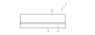
- FIG. 1 is a side view of the glass resin laminate according to the first embodiment.
- FIG. 2 is a plan view showing a cutting apparatus for a mother glass resin laminate according to the first embodiment.
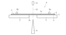
- FIG. 3 is a side view showing a cutting device for the mother glass resin laminate.
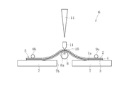
- FIG. 4 is a side view showing one step of a method for producing a glass resin laminate.
- FIG. 5 is a side view showing one step of a method for producing a glass resin laminate.
- FIG. 6 is a plan view showing one step of a method for producing a glass resin laminate.
- FIG. 7 is a side view showing one step of a method for producing a glass resin laminate.
- FIG. 8 is a side view showing one step of a method for producing a glass resin laminate.
- FIG. 1 is a side view of the glass resin laminate according to the first embodiment.
- FIG. 2 is a plan view showing a cutting apparatus for a mother glass resin laminate according to the first embodiment.
- FIG. 3 is a side view showing
- FIG. 9 is a side view showing one step of the method for producing a glass resin laminate.
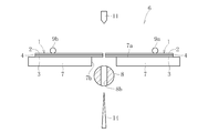
- FIG. 10 is a plan view showing a cutting device for a mother glass resin laminate according to the second embodiment.
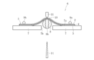
- FIG. 11 is a side view showing a cutting device for a mother glass resin laminate.
- FIG. 12 is a side view showing one step of a method for producing a glass resin laminate.
- FIG. 13 is a side view showing one step of a method for producing a glass resin laminate.
- FIG. 14 is a side view showing one step of a method for producing a glass resin laminate.
- FIG. 15 is a side view showing one step of a method for producing a glass resin laminate.
- FIG. 16 is a side view showing one step of a method for producing a glass resin laminate.
- FIG. 17 is a side view showing the mother glass resin laminate cutting apparatus according to the third embodiment.
- FIG. 18 is a side view showing one step of a method for producing a glass resin laminate.
- FIG. 19 is a side view showing one step of a method for producing a glass resin laminate.
- FIG. 20 is a side view showing one step of a method for producing a glass resin laminate.
- FIG. 21 is a side view of the glass resin laminate according to the fourth embodiment.
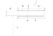
- FIG. 22 is a side view showing a mother glass resin laminate according to the fourth embodiment.
- FIG. 23 is a side view showing the mother glass resin laminate cutting apparatus according to the fourth embodiment.
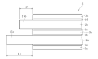
- FIG. 24 is a side view showing another example of the glass resin laminate.
- 25 is a side view showing a mother glass resin laminate for producing the glass resin laminate of FIG. FIG.
- FIG. 26 is a side view showing another example of the glass resin laminate.
- 27 is a side view showing a mother glass resin laminate for producing the glass resin laminate of FIG.
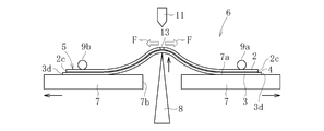
- FIG. 28 is a side view showing one step of the method for producing a glass resin laminate according to the fifth embodiment.
- FIG. 29 is a side view showing one step of a method for producing a glass resin laminate.
- FIG. 30 is an enlarged view of the vicinity of the cut end surface of the glass resin laminate of FIG.
- or FIG. 9 shows 1st embodiment of the manufacturing method of the glass resin laminated body which concerns on this invention.
- the glass resin laminate 1 includes a glass sheet 2, a resin layer 3, and an adhesive layer 4.
- the glass sheet 2 is preferably silicate glass or silica glass, more preferably borosilicate glass, soda lime glass, or aluminosilicate glass, and even more preferably alkali-free glass. When alkali-free glass is used, transparency is improved and deterioration due to alkali elution can be prevented.
- the glass sheet 2 can use what was shape
- the thickness of the glass sheet 2 is preferably 0.01 mm to 0.5 mm, more preferably 0.05 mm to 0.3 mm, and most preferably 0.05 mm to 0.2 mm.
- the resin layer 3 is not particularly limited, such as colored or colorless, transparent or translucent.
- Copolymers, ethylene-vinyl alcohol copolymers, ethylene-methacrylic acid copolymers, acrylics, polycarbonates, and the like can be used.
- the thickness of the resin layer 3 is preferably 0.01 mm to 1 mm, more preferably 0.015 mm to 0.5 mm, and most preferably 0.02 mm to 0.05 mm.
- the adhesive layer 4 is preferably transparent.
- a double-sided pressure-sensitive adhesive sheet, a thermoplastic adhesive sheet, a thermally crosslinkable adhesive sheet, an energy curable liquid adhesive, or the like can be used.
- the adhesive layer 4 includes, for example, an optically transparent adhesive sheet, an ethylene vinyl acetate copolymer (EVA), a thermoplastic polyurethane resin (TPU), a cycloolefin polymer (COP), an acrylic thermoplastic adhesive sheet, and an ultraviolet ray.
- EVA ethylene vinyl acetate copolymer
- TPU thermoplastic polyurethane resin
- COP cycloolefin polymer
- acrylic thermoplastic adhesive sheet and an ultraviolet ray.
- a curable adhesive, a thermosetting adhesive, or a room temperature curable adhesive can be used.
- the heel adhesive layer 4 may have an ultraviolet shielding function.
- the thickness of the adhesive layer 4 is preferably 0.005 mm to 0.5 mm, more preferably 0.01 mm to 0.1 mm, and
- a large glass sheet 2 and a resin sheet (resin layer 3) having a size substantially equal to that of the glass sheet 2 are laminated via an adhesive layer 4.
- the rectangular mother glass resin laminated body 5 (refer FIG. 2) is formed (mother glass resin laminated body formation process).
- the mother glass resin laminate 5 is not limited to a rectangular shape, but may be formed in a square shape or other shapes.
- the glass sheet, resin layer, and adhesive layer which are the components of the mother glass resin laminated body 5 it attaches
- the mother glass resin laminate 5 is cut by the cutting device 6 to form a plurality of glass resin laminates 1 (cutting step).
- the cutting device 6 includes a table (mounting table) 7 on which the mother glass resin laminate 5 is placed, a support 8 that supports a part of the mother glass resin laminate 5, and A plurality of (two in the illustrated example) pressing members 9 a and 9 b configured to sandwich a part of the mother glass resin laminate 5 together with the mounting table 7, and an initial crack 10 on the glass sheet 2 of the mother glass resin laminate 5.
- a crack imparting member 11 for forming In the mother glass resin laminate 5, virtual cutting lines 12 are set.
- the mounting table 7 includes a surface (mounting surface) 7a on which the mother glass resin laminate 5 is mounted and a slit 7b through which the support body 8 passes in the vertical direction.
- the support body 8 is configured to have a pointed shape. That is, the support 8 is configured as a knife (cutting tool) capable of cutting the resin layer 3.
- the support 8 is configured as a long member that is longer than the width (length) of the portion to be cut in the mother glass resin laminate 5. Further, the support 8 is configured to be movable in the vertical direction by a lifting device (not shown), and is configured to be movable in the horizontal direction by a moving mechanism (not shown).
- the holding members 9a and 9b are formed of a columnar or cylindrical elastic body.
- the pressing members 9a and 9b can be configured to be movable in the vertical direction and can be configured to be rotatable about the axis thereof.
- the holding members 9a and 9b include a first holding member 9a arranged on one end portion side of the mother glass resin laminate 5 and a second holding member 9b arranged on the other end portion side of the mother glass resin laminate 5. Including.
- the crack imparting member 11 has a pointed shape.
- the crack imparting member 11 is arranged above the mounting table 7 and is configured to be movable in the vertical direction and the horizontal direction.
- the mother glass resin laminate 5 is placed on the mounting table 7 with the support 8 and the crack imparting member 11 placed at predetermined standby positions. Put the body 5 on it.
- the resin layer 3 of the mother glass resin laminate 5 is set to face downward, and the resin layer 3 is brought into contact with the mounting surface 7 a of the mounting table 7. Thereafter, a part of the mother glass resin laminate 5 is pressed by the pressing members 9a and 9b.
- the support 8 in the standby position is raised and brought into contact with the mother glass resin laminate 5 so as to coincide with the planned cutting line 12.
- the support 8 protrudes upward from the mounting surface 7 a of the mounting table 7 through the slit 7 b of the mounting table 7.
- a part (middle portion) of the mother glass resin laminate 5 is lifted by the support 8 and is separated from the mounting table 7.
- the mother glass resin laminated body 5 is curved so that a part thereof is convex upward.
- the separation distance of the mounting table 7 (the slit width of the slit 7b) may be narrowed according to the degree of curvature of the mother glass resin laminate 5.
- bending stress is applied to the glass sheet 2 of the mother glass resin laminate 5 (bending stress applying step). Further, the tensile stress acts symmetrically with respect to the planned cutting line 12 on the mother glass resin laminate 5 by the support 8 and the pressing members 9a and 9b.
- the support body 8 that is a knife only supports the resin layer 3 of the mother glass resin laminate 5 and does not cut the resin layer 3. The support 8 is raised at a low speed so that the resin layer 3 is not cut, and the mother glass resin laminate 5 is curved.
- the crack imparting member 11 at the standby position is lowered and brought into contact with the glass sheet 2 of the mother glass resin laminate 5.
- the crack imparting member 11 is disposed such that the tip end (lower end) thereof coincides with the planned cutting line 12 in plan view.
- the crack imparting member 11 descends from the standby position and contacts the curved glass sheet 2.
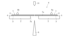
- the initial crack 10 is formed in the glass sheet 2 (giving process of the initial crack 10). Since bending stress is applied to the glass sheet 2, the initial crack 10 propagates along the planned cutting line 12. Thereby, the glass sheet 2 is cut along the planned cutting line 12 (see the cutting process of the glass sheet 2, see FIG. 6). In the portion where the glass sheet 2 is cleaved, a slight gap 13 is formed between the cut surfaces.
- the support 8 is moved along its longitudinal direction (horizontal direction).
- the support body 8 which is a knife slides while maintaining contact with the resin layer 3 of the mother glass resin laminate 5 by moving in the longitudinal direction.
- the support 8 may move in the longitudinal direction while moving upward, or may move in the longitudinal direction without moving upward.
- the support 8 is bonded to the resin layer 3 and the adhesive by the weight of the mother glass resin laminate 5, the tensile stress acting on the mother glass resin laminate 5, and the frictional force on the mother glass resin laminate 5 when the support 8 moves.
- Layer 4 is cut (see FIG. 8).
- the support 8 is lowered and returned to the standby position.
- the two glass resin laminates 1 formed by cutting the mother glass resin laminate 5 remain.
- the glass resin laminate 1 can be subjected to finishing steps such as a polishing step and a cleaning step. Further, the two glass resin laminates 1 can be used as new mother glass resin laminates 5 and the cutting process can be repeated in the same manner as described above to produce a smaller glass resin laminate 1.
- the mother glass resin laminate 5 is curved by the support 8 to apply bending stress to the glass sheet 2.
- the glass sheet 2 is cleaved along the planned cutting line 12.
- the fractured face of the glass sheet 2 can be configured in a good shape. Since the cleaving of the glass sheet 2 is performed before the resin layer 3 is cut, the glass sheet 2 is not damaged by the cutting of the resin layer 3. And this method can cut the mother glass resin laminated body 5 easily and rapidly, without passing through complicated processes like photolithography. Thereby, the manufacturing cost of the glass resin laminated body 1 can be reduced as much as possible.
- the support body 8 is comprised with a knife and the bending stress is given to the glass sheet 2 by supporting the mother glass resin laminated body 5 with this support body 8, it will cut
- the structure of the cutting device 6 differs from 1st embodiment.
- the support 8 is configured by a knife.
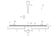
- the cutting device 6 is configured separately from the support 8 that can move in the vertical direction and the support 8. And a knife (cutting tool) 14 disposed above the support 8.
- the support 8 is formed in a cylindrical shape. With this configuration, the support 8 has a curved support surface that can support the mother glass resin laminate 5.
- the support body 8 has a groove portion 8a into which the knife 14 can be inserted.
- the knife 14 is configured to be movable in the vertical direction with its blade directed downward.
- Other configurations are the same as those of the first embodiment, and in the second embodiment, components common to the first embodiment are denoted by the same reference numerals as those of the first embodiment.
- the mother body is placed in a state where the support 8, the crack imparting member 11, and the knife 14 are arranged at predetermined standby positions (see FIGS. 10 and 11).
- the glass resin laminate 5 is placed on the mounting table 7
- a part of the mother glass resin laminate 5 is pressed by the pressing members 9a and 9b.
- the mother glass resin laminate 5 is placed on the mounting table 7 so that the resin layer 3 is in contact with the mounting surface 7a of the mounting table 7, as in the first embodiment.
- the support 8 is lifted from the standby position, passes through the slit 7b of the mounting table 7, and protrudes upward from the mounting surface 7a. Thereby, the support body 8 lifts up part (middle part) of the mother glass resin laminated body 5.
- FIG. The mother glass resin laminate 5 is curved so as to be convex upward by being supported by the support 8. Thereby, bending stress is applied to the glass sheet 2.
- the crack imparting member 11 at the standby position is moved, placed on the planned cutting line 12 of the glass sheet 2, and lowered to contact the glass sheet 2. Thereby, the initial crack 10 is formed in the glass sheet 2 (refer FIG. 13). Due to the action of bending stress applied to the glass sheet 2, the initial crack 10 propagates along the planned cutting line 12. Thereby, the glass sheet 2 is cleaved along the planned cutting line 12. Thereafter, the crack imparting member 11 rises and returns to the standby position (see FIG. 14).
- the knife 14 at the standby position is lowered to cut the resin layer 3.
- the knife 14 contacts the resin layer 3 through the gap 13 generated by cleaving the glass sheet 2.
- the knife 14 does not damage the fractured surface of the glass sheet 2.
- the knife 14 may be moved in the longitudinal direction and slid with respect to the resin layer 3. Since the knife 14 is inserted into the groove 8 a of the support 8 when cutting the resin layer 3, it does not contact the support 8.
- the knife 14 rises and returns to the standby position.
- the mother glass resin laminated body 5 is cut
- FIGS. 17 to 20 show a third embodiment of a method for producing a glass resin laminate.
- the structure of the cutting device 6 differs from 1st embodiment and 2nd embodiment.
- the cutting device 6 has the support body 8 provided with the groove portion 8a and the knife (cutting tool) 14 disposed above the support body 8, but in this embodiment, It has the support body 8 provided with the hole 8b, and the knife (cutting tool) 14 arrange
- the support 8 is formed in a columnar shape and has a curved support surface that can support the mother glass resin laminate 5.
- the support 8 has a hole 8b through which the knife 14 can pass.
- the hole 8b penetrates the support 8 in the radial direction.
- the penetration direction of the hole 8b coincides with the vertical direction (vertical direction).
- the knife 14 is configured to be movable in the vertical direction with its blade directed upward.
- Other configurations are the same as those in the first embodiment and the second embodiment, and in the third embodiment, the same reference numerals as those in the first embodiment are attached to the components common to the first embodiment and the second embodiment. is doing.
- the mother glass resin laminate 5 is formed in a state where the support 8, the crack imparting member 11 and the knife 14 are arranged at predetermined standby positions (see FIG. 17).
- the body 5 is placed on the mounting table 7
- a part of the mother glass resin laminate 5 is pressed by the pressing members 9a and 9b.
- the mother glass resin laminate 5 is placed on the mounting table 7 so that the resin layer 3 is in contact with the mounting surface 7a of the mounting table 7, as in the first and second embodiments. .
- the support body 8 is lifted from the standby position, passes through the slit 7b of the mounting table 7, and protrudes upward from the mounting surface 7a. Thereby, the support body 8 lifts up part (middle part) of the mother glass resin laminated body 5.
- FIG. The mother glass resin laminate 5 is curved so as to be convex upward by being supported by the support 8. Thereby, bending stress is applied to the glass sheet 2.
- the crack imparting member 11 at the standby position is lowered and brought into contact with the glass sheet 2. Thereby, the initial crack 10 is formed in the glass sheet 2 (refer FIG. 18). Due to the action of bending stress applied to the glass sheet 2, the initial crack 10 propagates along the planned cutting line 12. Thereby, the glass sheet 2 is cleaved along the planned cutting line 12. Thereafter, the crack imparting member 11 rises and returns to the standby position (see FIG. 19).
- the knife 14 at the standby position rises and cuts the resin layer 3.
- the knife 14 is inserted into the hole 8 b of the support 8 from the lower side, and the tip thereof contacts the resin layer 3.
- the resin layer 3 is cut by further raising the knife 14.
- the knife 14 may be moved in the longitudinal direction and slid with respect to the resin layer 3. Since the knife 14 is inserted into the hole 8b of the support 8 when cutting the resin layer 3, it does not contact the support 8.
- the knife 14 descends and returns to the standby position. Thereafter, the support 8 is lowered and returned to the standby position.
- the mother glass resin laminated body 5 is cut
- the glass resin laminate 1 includes a single glass sheet 2 and two resin layers 3a and 3b. Specifically, as shown in FIG. 21, the glass resin laminate 1 includes a first resin layer 3 a laminated on one surface of the glass sheet 2 and a second resin laminated on the other surface of the glass sheet 2. It has the resin layer 3b, the 1st contact bonding layer 4a which adhere
- the mother glass resin laminate 5 for producing the glass resin laminate 1 is a first resin having an area smaller than the area of the glass sheet 2 on both sides of the large glass sheet 2 as shown in FIG.
- the layer 3a and the second resin layer 3b are laminated. Since the glass sheet 2 is larger than the resin layers 3a and 3b, the glass sheet 2 has a portion (protrusion) 15 protruding outward from the end of each resin layer 3a and 3b at one end thereof.
- the mother glass resin laminate 5 is curved by bringing the support 8 into contact with the upper surface of the mother glass resin laminate 5 and further lowering it.
- the cutting device 6 includes a support 8 configured as a knife, a crack imparting member 11, and a plurality of (two pairs in the illustrated example) roller pairs 16a as holding members for the mother glass resin laminate 5. 16b.
- the cutting device 6 includes a support 8 disposed above the mother glass resin laminate 5 and a crack imparting member 11 disposed below the mother glass resin laminate 5.
- the mother glass resin laminate 5 is held (clamped) by the roller pairs 16a and 16b, and then the support 8 in the standby position is moved downward. And contact with the second resin layer 3 b of the mother glass resin laminate 5.
- the support 8 is further moved downward, the mother glass resin laminate 5 is pushed down by the support 8 as shown by a two-dot chain line in FIG. .
- the crack imparting member 11 rises and comes into contact with the glass sheet 2 of the mother glass resin laminate 5 to form the initial crack 10. At this time, the crack imparting member 11 comes into contact with the protruding portion 15 in the glass sheet 2 of the mother glass resin laminate 5. Thereby, the crack provision member 11 can form the initial stage crack 10 in the glass sheet 2, without contacting the 2nd resin layer 3b.
- the initial crack 10 is propagated along the planned cutting line 12 to cleave the glass sheet 2.
- the support body 8 is moved down and moved in the longitudinal direction, and is slid with respect to the second resin layer 3b to cut the second resin layer 3b. Thereafter, the first resin layer 3a is cut in the same manner.
- the mother glass resin laminated body 5 is cut
- FIGS. 24 to 27 show other examples of the glass resin laminate and the mother glass resin laminate.
- the glass resin laminate 1 includes two layers of glass sheets 2a and 2b and two layers of resin layers 3a and 3b.
- the glass resin laminate 1 and the mother glass resin laminate 5 are a first glass sheet 2a, a second glass sheet 2b, and a first resin layer 3a fixed to one surface of the first glass sheet 2a.
- a second resin layer 3b provided between the other surface of the first glass sheet 2a and the second glass sheet 2b; a first adhesive layer 4a that bonds the first glass sheet 2a and the first resin layer 3a; The second adhesive layer 4b that bonds the other surface of the first glass sheet 2a and the second resin layer 3b, and the third adhesive layer 4c that bonds the second resin layer 3b and the second glass sheet 2b. .
- the 1st glass sheet 2a of the mother glass resin laminated body 5 has the protrusion part 15 in the edge part similarly to 3rd embodiment.
- the second glass sheet 2 b of the mother glass resin laminate 5 does not have the protruding portion 15. In order to cut this mother glass resin laminate 5, it is desirable to cleave the first glass sheet 2a after cleaving the second glass sheet 2b.
- the glass resin laminate 1 has two glass sheets 2a and 2b and three resin layers 3a to 3c.
- the glass resin laminate 1 and the mother glass resin laminate 5 include a first glass sheet 2a and a second glass sheet 2b, a first resin layer 3a to a third resin layer 3c, and each glass sheet 2a, 2b and resin layers 3a to 3c are bonded to each other, and first adhesive layer 4a to fourth adhesive layer 4d.
- the first glass sheet 2a of the mother glass resin laminate 5 has a portion (first protruding portion) 15a that protrudes outward from the end portions of the resin layers 3a to 3c.
- the second glass sheet 2b of the mother glass resin laminate 5 has a portion (second protruding portion) 15b that protrudes outward from the end portions of the resin layers 3a to 3c.
- the protrusion length L1 of the first protrusion 15a is larger than the protrusion length L2 of the second protrusion 15b.
- or FIG. 30 shows 5th embodiment of the manufacturing method of a glass resin laminated body.
- the mother glass resin laminate according to the present embodiment includes a single glass sheet 2, a single resin layer 3, and an adhesive layer 4 that joins the glass sheet 2 and the resin layer 3.
- the area of the resin layer 3 is larger than the area of the glass sheet 2. Therefore, the peripheral edge of the resin layer 3 protrudes from the glass sheet 2. Specifically, the end 3 d of the resin layer 3 protrudes from the end 2 c of the glass sheet 2.
- the pair of mounting tables 7 in the cutting device 6 are configured to be movable in the horizontal direction. That is, the cutting device 6 holds one end portion of the mother glass resin laminate 5 by the holding member 9a corresponding to one mounting table 7, and the mother glass resin by the pressing member 9b corresponding to the other mounting table 7. The other end of the stacked body 5 is held.
- the cutting device 6 applies a tensile force F to the mother glass resin laminate 5 by moving the pair of mounting tables 7 so as to be separated from each other in this holding state. Thereby, a tensile stress can be applied to the planned cutting portion (portion supported by the support 8) of the mother glass resin laminate 5 in a direction perpendicular to the cutting direction (advancing direction of the support 8).
- FIG. 28 shows the cutting device 6 after the cleaving process of the glass sheet 2.
- a gap 13 is formed in the glass sheet 2 of the mother glass resin laminate 5 by cleaving.
- the support body 8 also serving as a knife supports the resin layer 3 of the mother glass resin laminate 5. From this state, the cutting device 6 raises the support 8 and separates the pair of mounting tables 7 together with the pressing members 9a and 9b in the horizontal direction.
- the resin layer 3 is stretched by the mounting table 7 and the support 8 and is plastically deformed.
- the end 3e of the resin layer 3 formed by the cutting is more than the end 2d of the glass sheet 2 as shown in FIG. Will also protrude. Furthermore, the protruding portion 3a1 of the resin layer 3 protruding from the end 2d of the glass sheet 2 is thinner than the thickness of the laminated portion 3a2 of the resin layer 3 with the glass sheet 2 due to the plastic deformation described above.
- the glass resin laminate 1 formed as described above can protect the peripheral portion of the glass sheet 2 by the resin layer 3 protruding from the glass sheet 2.
- the present invention is not limited to this configuration.
- the step of stretching the resin layer 3 may be performed only by raising the support 8 or only by moving the mounting table 7. Further, the resin layer 3 may be stretched by lowering the mounting table 7 together with the pressing members 9a and 9b.
- the cutting device 6 may be provided with a clamp mechanism capable of gripping the mother glass resin laminate 5, and the resin layer 3 may be stretched by the clamp mechanism.
- an example in which the resin layer 3 is stretched so as to be plastically deformed has been shown.
- the present invention is not limited to this, and the resin layer 3 may be stretched so as to be elastically deformed and cut. In this case, after the resin layer 3 is cut, the end portion 3e of the resin layer 3 is projected from the end portion 2d of the glass sheet 2 by performing processing such as grinding on the end portion 2d of the glass sheet 2 at the cut portion. Can do.
- this invention is not limited to the structure of the said embodiment, It is not limited to the above-mentioned effect.
- the present invention can be variously modified without departing from the gist of the present invention.
- the glass resin laminate 1 according to the present invention is not limited to the above embodiment, and includes three or more layers of glass sheets 2 and four or more layers of resin layers 3. That is, the present invention is applied to the glass resin laminate 1 and the mother glass resin laminate 5 having at least one glass sheet 2 and at least one resin layer 3.
- the glass sheet in the mother glass resin laminate 5 in which the resin layers 3 are bonded to both surfaces of the glass sheet 2 (first glass sheet 2a, second glass sheet 2b), the glass sheet Although the protrusion 15 (15a, 15b) is formed at the end of 2, even the mother glass resin laminate 5 that does not form the protrusion 15 can form the initial crack 10 in the glass sheet 2. .
- the end face of the glass sheet 2 and the end face of the resin layer 3 are configured to be flush with each other, but the initial crack 10 can be formed by bringing the crack imparting member 11 into contact with the end face of the glass sheet 2. .
- the glass sheet 2 may be cleaved by applying a bending stress to the mother glass resin laminate 5 after forming the initial crack 10 on the horizontal glass sheet 2 by the crack applying member 11.
- the present invention is not limited to these examples.
- the inventor produced glass resin laminates according to Examples 1 to 6 and Comparative Examples 1 and 2.
- the thickness of the glass sheet is set to 100 ⁇ m
- the thickness of the resin layer is set to 38 ⁇ m
- the thickness of the adhesive layer is set to 25 ⁇ m.
- Table 1 shows the conditions and determination results (cutting quality) of each example.
- the glass resin laminate according to Example 1 has a single glass sheet (glass layer) and a single resin layer (corresponding to the example of FIG. 1).
- a cylindrical bar having a diameter of 5 mm was used as the support, and the mother glass resin laminate was bent. Specifically, the mother glass resin laminate is lifted by this support and is bent so as to be convex upward, and an initial crack is formed in the glass sheet and then cut, and then the resin is prepared using a knife prepared separately from the support. The layers were cut to produce a glass resin laminate. In Example 1, a good cut surface could be obtained, and the cutting quality was “ ⁇ ” (good).
- the glass resin laminate according to Example 2 has a single glass sheet (glass layer) and a single resin layer.
- a knife was used as the support, and the mother glass resin laminate was lifted by this support and curved so as to be convex upward. Thereafter, initial cracks were formed in the glass sheet and cleaved, and the resin layer was cut with this knife to produce a glass resin laminate.
- a very good cut surface could be obtained, and the cutting quality was “ ⁇ ” (best).
- the glass resin laminate according to Example 3 has a single glass sheet (glass layer) and two resin layers bonded to both surfaces of the glass sheet (corresponding to the example in FIG. 21).
- a knife was used as the support, and the mother glass resin laminate was lifted by this support and curved so as to be convex upward. Thereafter, an initial crack was formed in the glass sheet and cleaved, and the glass resin laminate was produced by cutting the two resin layers with this knife. In Example 3, a very good cut surface could be obtained, and the cutting quality was “ ⁇ ” (best).
- the glass resin laminate according to Example 4 has a two-layer glass sheet (glass layer) and a two-layer resin layer (corresponding to the example of FIG. 24).
- the mother glass resin laminate the one illustrated in FIG. 25 was used.
- a knife was used as the support, and the mother glass resin laminate was pushed down by this support and curved so as to be convex downward.
- the initial crack was formed in the protrusion part of the 1st glass sheet, and the said 1st glass sheet was cleaved. Thereafter, an initial crack was formed in the second glass sheet, and the second glass sheet was cleaved.
- the two resin layers were cut with a knife supporting the mother glass resin laminate, and a glass resin laminate was produced. In Example 4, a very good cut surface could be obtained, and the cutting quality was “ ⁇ ” (best).
- the glass resin laminate according to Example 5 has a two-layer glass sheet (glass layer) and a two-layer resin layer (corresponding to the example of FIG. 24).
- the mother glass resin laminate the one illustrated in FIG. 25 was used.
- a knife was used as the support, and the mother glass resin laminate was lifted by this support and curved so as to be convex upward.
- An initial crack was formed in the second glass sheet, and the second glass sheet was cleaved.
- the initial crack was formed in the protrusion part of the 1st glass sheet, and the said 1st glass sheet was cleaved.
- the two resin layers were cut with a knife supporting the mother glass resin laminate, and a glass resin laminate was produced.
- a very good cut surface could be obtained, and the cutting quality was “ ⁇ ” (best).
- the glass resin laminate according to Example 6 has a single glass sheet (glass layer) and a single resin layer.
- the mother glass resin laminate the one illustrated in FIG. 28 was used.
- a knife was used as the support, and the mother glass resin laminate was lifted by this support and curved so as to be convex upward. Thereafter, an initial crack is formed in the glass sheet and cleaved.
- the resin layer in the vicinity of the planned cutting portion is stretched by applying a tensile stress to the planned cutting portion, and then the resin layer is cut with a knife to obtain a glass resin laminate.
- Manufactured In Example 6, a very good cut surface could be obtained, and the cutting quality was “ ⁇ ” (best).
- the glass resin laminate according to Comparative Example 1 has a single glass sheet (glass layer) and a single resin layer.
- the glass sheet was cleaved with a scribe tool.
- the cutting quality of Comparative Example 1 was set to “x” (most defective).
- the glass resin laminate according to Comparative Example 2 has a single glass sheet (glass layer) and a single resin layer.
- Comparative Example 2 after the resin layer of the mother glass resin laminate was cut with a knife, bending stress was applied to the mother glass resin laminate, an initial crack was formed in the glass sheet, and the glass sheet was cleaved. In Comparative Example 2, the glass sheet was damaged when the resin layer was cut, and the scratch remained in the manufactured glass resin laminate. For this reason, the cutting quality of Comparative Example 2 was set to “ ⁇ ” (defective).
Landscapes
- Chemical & Material Sciences (AREA)
- Engineering & Computer Science (AREA)
- Materials Engineering (AREA)
- Organic Chemistry (AREA)
- Mechanical Engineering (AREA)
- Laminated Bodies (AREA)
- Re-Forming, After-Treatment, Cutting And Transporting Of Glass Products (AREA)
- Processing Of Stones Or Stones Resemblance Materials (AREA)
- Perforating, Stamping-Out Or Severing By Means Other Than Cutting (AREA)
- Nonmetal Cutting Devices (AREA)
- Joining Of Glass To Other Materials (AREA)
Abstract
Description

2 ガラスシート
2a ガラスシート(第一ガラスシート)
2b ガラスシート(第二ガラスシート)
3 樹脂層
3a 樹脂層(第一樹脂層)
3a1 突出部
3a2 積層部
3b 樹脂層(第二樹脂層)
3c 樹脂層(第三樹脂層)
5 マザーガラス樹脂積層体
8 支持体
10 初期クラック
Claims (7)
- ガラスシートと樹脂層とを積層してなるマザーガラス樹脂積層体を切断することにより、ガラス樹脂積層体を製造する方法であって、
前記マザーガラス樹脂積層体を湾曲させることにより前記ガラスシートに曲げ応力を付与する工程と、前記曲げ応力を付与した前記ガラスシートを割断する工程と、前記ガラスシートの割断後に前記樹脂層を切断する工程と、を備えることを特徴とする、ガラス樹脂積層体の製造方法。 - 前記ガラスシートを割断する工程は、前記ガラスシートに曲げ応力を付与した後に、前記ガラスシートに初期クラックを形成することにより、前記ガラスシートを割断する請求項1に記載のガラス樹脂積層体の製造方法。
- 前記樹脂層に接触して前記マザーガラス樹脂積層体を下方から持ち上げることにより、前記マザーガラス樹脂積層体を湾曲させる支持体を備え、
前記支持体は、前記樹脂層を切断可能な切断具である請求項1又は2に記載のガラス樹脂積層体の製造方法。 - 前記ガラスシートは、前記樹脂層の端部よりも外方に突出する突出部を有する請求項1から3のいずれか1項に記載のガラス樹脂積層体の製造方法。
- 前記支持体は、前記樹脂層に対して摺動することにより、前記樹脂層を切断する請求項3に記載のガラス樹脂積層体の製造方法。
- 前記ガラスシートを割断する工程の後に、前記樹脂層を引き伸ばす工程をさらに備え、前記樹脂層を引き伸ばした後に前記樹脂層を切断する請求項1から5のいずれか1項に記載のガラス樹脂積層体の製造方法。
- ガラスシートと樹脂層とを積層してなるマザーガラス樹脂積層体を切断することにより製造されたガラス樹脂積層体であって、
前記樹脂層は、前記ガラスシートの端部から前記樹脂層の端部が突出している突出部と、前記ガラスシートと積層されている積層部とを有し、
前記突出部には、前記積層部の厚さよりも薄い部分が存在することを特徴とするガラス樹脂積層体。
Priority Applications (3)
| Application Number | Priority Date | Filing Date | Title |
|---|---|---|---|
| JP2018543889A JP6963754B2 (ja) | 2016-10-05 | 2017-10-02 | ガラス樹脂積層体の製造方法及びガラス樹脂積層体 |
| KR1020197008994A KR102322397B1 (ko) | 2016-10-05 | 2017-10-02 | 유리 수지 적층체의 제조 방법 및 유리 수지 적층체 |
| CN201780059751.2A CN109790059B (zh) | 2016-10-05 | 2017-10-02 | 玻璃树脂层叠体的制造方法及玻璃树脂层叠体 |
Applications Claiming Priority (2)
| Application Number | Priority Date | Filing Date | Title |
|---|---|---|---|
| JP2016197121 | 2016-10-05 | ||
| JP2016-197121 | 2016-10-05 |
Publications (1)
| Publication Number | Publication Date |
|---|---|
| WO2018066508A1 true WO2018066508A1 (ja) | 2018-04-12 |
Family
ID=61831103
Family Applications (1)
| Application Number | Title | Priority Date | Filing Date |
|---|---|---|---|
| PCT/JP2017/035814 Ceased WO2018066508A1 (ja) | 2016-10-05 | 2017-10-02 | ガラス樹脂積層体の製造方法及びガラス樹脂積層体 |
Country Status (5)
| Country | Link |
|---|---|
| JP (1) | JP6963754B2 (ja) |
| KR (1) | KR102322397B1 (ja) |
| CN (1) | CN109790059B (ja) |
| TW (1) | TWI744390B (ja) |
| WO (1) | WO2018066508A1 (ja) |
Cited By (4)
| Publication number | Priority date | Publication date | Assignee | Title |
|---|---|---|---|---|
| WO2022102470A1 (ja) * | 2020-11-13 | 2022-05-19 | 日東電工株式会社 | 複層構造体及びその製造方法 |
| WO2022153859A1 (ja) * | 2021-01-12 | 2022-07-21 | 日本電気硝子株式会社 | ガラスフィルムの製造方法 |
| WO2023120246A1 (ja) * | 2021-12-23 | 2023-06-29 | 日本電気硝子株式会社 | 積層体の製造方法 |
| WO2024106215A1 (ja) * | 2022-11-16 | 2024-05-23 | 日本電気硝子株式会社 | ガラス物品の製造方法、及びガラス物品の製造装置 |
Families Citing this family (1)
| Publication number | Priority date | Publication date | Assignee | Title |
|---|---|---|---|---|
| KR20220015838A (ko) * | 2020-07-31 | 2022-02-08 | 코닝 인코포레이티드 | 유리 라미네이트 기판의 절단 장치 및 절단 방법 |
Citations (7)
| Publication number | Priority date | Publication date | Assignee | Title |
|---|---|---|---|---|
| JPH07291648A (ja) * | 1994-04-27 | 1995-11-07 | Sumitomo Chem Co Ltd | 合わせガラスの切断方法 |
| JP2003255362A (ja) * | 2002-03-05 | 2003-09-10 | Citizen Watch Co Ltd | セルとその製造方法およびそのセルを用いた液晶光学素子 |
| JP2006321679A (ja) * | 2005-05-19 | 2006-11-30 | Glass Assist:Kk | 合わせ板ガラスの切断方法および切断用加熱器具 |
| JP2012201573A (ja) * | 2011-03-28 | 2012-10-22 | Asahi Glass Co Ltd | 脆性板の切断装置および切断方法 |
| JP2014097905A (ja) * | 2012-11-13 | 2014-05-29 | Nippon Electric Glass Co Ltd | ガラス板積層体及びその製造方法 |
| JP2015083336A (ja) * | 2013-10-25 | 2015-04-30 | 三星ダイヤモンド工業株式会社 | 脆性材料基板の分断方法並びに分断装置 |
| JP2015101044A (ja) * | 2013-11-27 | 2015-06-04 | 日本電気硝子株式会社 | 化学強化ガラス樹脂積層体及びその製造方法 |
Family Cites Families (8)
| Publication number | Priority date | Publication date | Assignee | Title |
|---|---|---|---|---|
| JP2004354836A (ja) * | 2003-05-30 | 2004-12-16 | Casio Comput Co Ltd | ガラス基板分断方法及びその装置 |
| AU2003277938A1 (en) * | 2003-11-06 | 2005-05-26 | Peter Lisec | Device for cutting glass and for removing a coating thereon |
| CN102672741B (zh) * | 2008-01-15 | 2015-06-03 | 三星钻石工业股份有限公司 | 切刀 |
| KR102022754B1 (ko) * | 2012-06-15 | 2019-09-18 | 가부시키가이샤 토쿄 세이미쯔 | 다이싱 장치 및 다이싱 방법 |
| JP2014159352A (ja) | 2013-02-20 | 2014-09-04 | Nitto Denko Corp | 可撓性フィルムの製造方法 |
| JP5995097B2 (ja) | 2013-04-30 | 2016-09-21 | 日本電気硝子株式会社 | 複合板の切断方法 |
| JP6548425B2 (ja) * | 2014-03-31 | 2019-07-24 | 日鉄ケミカル&マテリアル株式会社 | フレキシブルデバイスの製造方法及びフレキシブルデバイス並びにフレキシブルデバイス製造装置 |
| JP2016013928A (ja) * | 2014-06-12 | 2016-01-28 | 日本電気硝子株式会社 | ガラスパネル体の切断方法 |
-
2017
- 2017-10-02 KR KR1020197008994A patent/KR102322397B1/ko active Active
- 2017-10-02 WO PCT/JP2017/035814 patent/WO2018066508A1/ja not_active Ceased
- 2017-10-02 CN CN201780059751.2A patent/CN109790059B/zh active Active
- 2017-10-02 JP JP2018543889A patent/JP6963754B2/ja active Active
- 2017-10-05 TW TW106134328A patent/TWI744390B/zh active
Patent Citations (7)
| Publication number | Priority date | Publication date | Assignee | Title |
|---|---|---|---|---|
| JPH07291648A (ja) * | 1994-04-27 | 1995-11-07 | Sumitomo Chem Co Ltd | 合わせガラスの切断方法 |
| JP2003255362A (ja) * | 2002-03-05 | 2003-09-10 | Citizen Watch Co Ltd | セルとその製造方法およびそのセルを用いた液晶光学素子 |
| JP2006321679A (ja) * | 2005-05-19 | 2006-11-30 | Glass Assist:Kk | 合わせ板ガラスの切断方法および切断用加熱器具 |
| JP2012201573A (ja) * | 2011-03-28 | 2012-10-22 | Asahi Glass Co Ltd | 脆性板の切断装置および切断方法 |
| JP2014097905A (ja) * | 2012-11-13 | 2014-05-29 | Nippon Electric Glass Co Ltd | ガラス板積層体及びその製造方法 |
| JP2015083336A (ja) * | 2013-10-25 | 2015-04-30 | 三星ダイヤモンド工業株式会社 | 脆性材料基板の分断方法並びに分断装置 |
| JP2015101044A (ja) * | 2013-11-27 | 2015-06-04 | 日本電気硝子株式会社 | 化学強化ガラス樹脂積層体及びその製造方法 |
Cited By (5)
| Publication number | Priority date | Publication date | Assignee | Title |
|---|---|---|---|---|
| WO2022102470A1 (ja) * | 2020-11-13 | 2022-05-19 | 日東電工株式会社 | 複層構造体及びその製造方法 |
| WO2022153859A1 (ja) * | 2021-01-12 | 2022-07-21 | 日本電気硝子株式会社 | ガラスフィルムの製造方法 |
| WO2023120246A1 (ja) * | 2021-12-23 | 2023-06-29 | 日本電気硝子株式会社 | 積層体の製造方法 |
| JP2023094076A (ja) * | 2021-12-23 | 2023-07-05 | 日本電気硝子株式会社 | 積層体の製造方法 |
| WO2024106215A1 (ja) * | 2022-11-16 | 2024-05-23 | 日本電気硝子株式会社 | ガラス物品の製造方法、及びガラス物品の製造装置 |
Also Published As
| Publication number | Publication date |
|---|---|
| KR20190066006A (ko) | 2019-06-12 |
| KR102322397B1 (ko) | 2021-11-05 |
| TWI744390B (zh) | 2021-11-01 |
| TW201821284A (zh) | 2018-06-16 |
| CN109790059B (zh) | 2021-11-16 |
| JP6963754B2 (ja) | 2021-11-10 |
| JPWO2018066508A1 (ja) | 2019-07-18 |
| CN109790059A (zh) | 2019-05-21 |
Similar Documents
| Publication | Publication Date | Title |
|---|---|---|
| JP6963754B2 (ja) | ガラス樹脂積層体の製造方法及びガラス樹脂積層体 | |
| JP5029523B2 (ja) | ガラス積層体、支持体付き表示装置用パネル、表示装置用パネル、表示装置およびこれらの製造方法 | |
| US9212080B2 (en) | Glass film cleaving method and glass film laminate | |
| US20220259092A1 (en) | Method for dividing composite material | |
| KR102953361B1 (ko) | 복합재의 분단 방법 | |
| US12338160B2 (en) | Method for dividing composite material | |
| CN104552629A (zh) | 破断装置以及分断方法 | |
| CN101251669A (zh) | 液晶面板显示单元的制造方法及其结构 | |
| KR20200135614A (ko) | 유리 기판 절단 방법 및 도광판 제조 방법 | |
| US10246374B2 (en) | Method for manufacturing glass film laminate, glass film laminate, and method for manufacturing electronic device | |
| JP2019156651A (ja) | ガラス基板切断装置およびこれを用いた液晶パネルの製造方法 | |
| CN104552630B (zh) | 弹性支撑板、破断装置以及分断方法 | |
| KR102400550B1 (ko) | 합착 기판의 절단 시스템 | |
| JP6222439B2 (ja) | ガラスフィルムの割断方法及びフィルム状ガラスの製造方法 | |
| KR101877462B1 (ko) | 디스플레이 패널 절단 방법 | |
| WO2023120246A1 (ja) | 積層体の製造方法 | |
| JP6079249B2 (ja) | ガラス板−樹脂板積層体 | |
| JP2023089634A (ja) | シート材の分断方法 | |
| WO2017018136A1 (ja) | ガラスフィルムの製造方法、及びガラスフィルムを含む電子デバイスの製造方法 | |
| JP2022166863A (ja) | 積層体および積層体の製造方法 | |
| KR101696719B1 (ko) | 단차부가 있는 취성 합착패널의 스크라이빙 방법 | |
| TWI887666B (zh) | 玻璃板的製造方法以及刻劃裝置 | |
| JP2024004015A (ja) | シート材の分断方法及びシート材の分断装置 | |
| CN104039719B (zh) | 玻璃薄膜的切割方法 | |
| JP2008071616A (ja) | 有機el素子パネルとその製造方法 |
Legal Events
| Date | Code | Title | Description |
|---|---|---|---|
| 121 | Ep: the epo has been informed by wipo that ep was designated in this application |
Ref document number: 17858346 Country of ref document: EP Kind code of ref document: A1 |
|
| ENP | Entry into the national phase |
Ref document number: 2018543889 Country of ref document: JP Kind code of ref document: A |
|
| ENP | Entry into the national phase |
Ref document number: 20197008994 Country of ref document: KR Kind code of ref document: A |
|
| NENP | Non-entry into the national phase |
Ref country code: DE |
|
| 122 | Ep: pct application non-entry in european phase |
Ref document number: 17858346 Country of ref document: EP Kind code of ref document: A1 |