WO2018062186A1 - ハニカム構造体とその製造方法及び排ガス浄化フィルタ - Google Patents
ハニカム構造体とその製造方法及び排ガス浄化フィルタ Download PDFInfo
- Publication number
- WO2018062186A1 WO2018062186A1 PCT/JP2017/034758 JP2017034758W WO2018062186A1 WO 2018062186 A1 WO2018062186 A1 WO 2018062186A1 JP 2017034758 W JP2017034758 W JP 2017034758W WO 2018062186 A1 WO2018062186 A1 WO 2018062186A1
- Authority
- WO
- WIPO (PCT)
- Prior art keywords
- cell
- cells
- honeycomb structure
- plugged
- incomplete
- Prior art date
- Legal status (The legal status is an assumption and is not a legal conclusion. Google has not performed a legal analysis and makes no representation as to the accuracy of the status listed.)
- Ceased
Links
Images


Classifications
-
- B—PERFORMING OPERATIONS; TRANSPORTING
- B01—PHYSICAL OR CHEMICAL PROCESSES OR APPARATUS IN GENERAL
- B01D—SEPARATION
- B01D46/00—Filters or filtering processes specially modified for separating dispersed particles from gases or vapours
- B01D46/24—Particle separators, e.g. dust precipitators, using rigid hollow filter bodies
- B01D46/2403—Particle separators, e.g. dust precipitators, using rigid hollow filter bodies characterised by the physical shape or structure of the filtering element
- B01D46/2418—Honeycomb filters
- B01D46/2451—Honeycomb filters characterized by the geometrical structure, shape, pattern or configuration or parameters related to the geometry of the structure
- B01D46/2459—Honeycomb filters characterized by the geometrical structure, shape, pattern or configuration or parameters related to the geometry of the structure of the plugs
-
- F—MECHANICAL ENGINEERING; LIGHTING; HEATING; WEAPONS; BLASTING
- F01—MACHINES OR ENGINES IN GENERAL; ENGINE PLANTS IN GENERAL; STEAM ENGINES
- F01N—GAS-FLOW SILENCERS OR EXHAUST APPARATUS FOR MACHINES OR ENGINES IN GENERAL; GAS-FLOW SILENCERS OR EXHAUST APPARATUS FOR INTERNAL-COMBUSTION ENGINES
- F01N3/00—Exhaust or silencing apparatus having means for purifying, rendering innocuous, or otherwise treating exhaust
- F01N3/02—Exhaust or silencing apparatus having means for purifying, rendering innocuous, or otherwise treating exhaust for cooling, or for removing solid constituents of, exhaust
- F01N3/021—Exhaust or silencing apparatus having means for purifying, rendering innocuous, or otherwise treating exhaust for cooling, or for removing solid constituents of, exhaust by means of filters
- F01N3/022—Exhaust or silencing apparatus having means for purifying, rendering innocuous, or otherwise treating exhaust for cooling, or for removing solid constituents of, exhaust by means of filters characterised by specially adapted filtering structure, e.g. honeycomb, mesh or fibrous
- F01N3/0222—Exhaust or silencing apparatus having means for purifying, rendering innocuous, or otherwise treating exhaust for cooling, or for removing solid constituents of, exhaust by means of filters characterised by specially adapted filtering structure, e.g. honeycomb, mesh or fibrous the structure being monolithic, e.g. honeycombs
-
- B—PERFORMING OPERATIONS; TRANSPORTING
- B01—PHYSICAL OR CHEMICAL PROCESSES OR APPARATUS IN GENERAL
- B01D—SEPARATION
- B01D39/00—Filtering material for liquid or gaseous fluids
- B01D39/14—Other self-supporting filtering material ; Other filtering material
- B01D39/20—Other self-supporting filtering material ; Other filtering material of inorganic material, e.g. asbestos paper, metallic filtering material of non-woven wires
-
- B—PERFORMING OPERATIONS; TRANSPORTING
- B01—PHYSICAL OR CHEMICAL PROCESSES OR APPARATUS IN GENERAL
- B01D—SEPARATION
- B01D46/00—Filters or filtering processes specially modified for separating dispersed particles from gases or vapours
-
- B—PERFORMING OPERATIONS; TRANSPORTING
- B01—PHYSICAL OR CHEMICAL PROCESSES OR APPARATUS IN GENERAL
- B01D—SEPARATION
- B01D46/00—Filters or filtering processes specially modified for separating dispersed particles from gases or vapours
- B01D46/0001—Making filtering elements
-
- B—PERFORMING OPERATIONS; TRANSPORTING
- B01—PHYSICAL OR CHEMICAL PROCESSES OR APPARATUS IN GENERAL
- B01D—SEPARATION
- B01D46/00—Filters or filtering processes specially modified for separating dispersed particles from gases or vapours
- B01D46/24—Particle separators, e.g. dust precipitators, using rigid hollow filter bodies
- B01D46/2403—Particle separators, e.g. dust precipitators, using rigid hollow filter bodies characterised by the physical shape or structure of the filtering element
- B01D46/2418—Honeycomb filters
- B01D46/2451—Honeycomb filters characterized by the geometrical structure, shape, pattern or configuration or parameters related to the geometry of the structure
- B01D46/247—Honeycomb filters characterized by the geometrical structure, shape, pattern or configuration or parameters related to the geometry of the structure of the cells
-
- B—PERFORMING OPERATIONS; TRANSPORTING
- B01—PHYSICAL OR CHEMICAL PROCESSES OR APPARATUS IN GENERAL
- B01D—SEPARATION
- B01D46/00—Filters or filtering processes specially modified for separating dispersed particles from gases or vapours
- B01D46/24—Particle separators, e.g. dust precipitators, using rigid hollow filter bodies
- B01D46/2403—Particle separators, e.g. dust precipitators, using rigid hollow filter bodies characterised by the physical shape or structure of the filtering element
- B01D46/2418—Honeycomb filters
- B01D46/2451—Honeycomb filters characterized by the geometrical structure, shape, pattern or configuration or parameters related to the geometry of the structure
- B01D46/2474—Honeycomb filters characterized by the geometrical structure, shape, pattern or configuration or parameters related to the geometry of the structure of the walls along the length of the honeycomb
-
- B—PERFORMING OPERATIONS; TRANSPORTING
- B01—PHYSICAL OR CHEMICAL PROCESSES OR APPARATUS IN GENERAL
- B01D—SEPARATION
- B01D46/00—Filters or filtering processes specially modified for separating dispersed particles from gases or vapours
- B01D46/24—Particle separators, e.g. dust precipitators, using rigid hollow filter bodies
- B01D46/2403—Particle separators, e.g. dust precipitators, using rigid hollow filter bodies characterised by the physical shape or structure of the filtering element
- B01D46/2418—Honeycomb filters
- B01D46/2451—Honeycomb filters characterized by the geometrical structure, shape, pattern or configuration or parameters related to the geometry of the structure
- B01D46/2482—Thickness, height, width, length or diameter
-
- B—PERFORMING OPERATIONS; TRANSPORTING
- B01—PHYSICAL OR CHEMICAL PROCESSES OR APPARATUS IN GENERAL
- B01D—SEPARATION
- B01D46/00—Filters or filtering processes specially modified for separating dispersed particles from gases or vapours
- B01D46/24—Particle separators, e.g. dust precipitators, using rigid hollow filter bodies
- B01D46/2403—Particle separators, e.g. dust precipitators, using rigid hollow filter bodies characterised by the physical shape or structure of the filtering element
- B01D46/2418—Honeycomb filters
- B01D46/2451—Honeycomb filters characterized by the geometrical structure, shape, pattern or configuration or parameters related to the geometry of the structure
- B01D46/2484—Cell density, area or aspect ratio
-
- B—PERFORMING OPERATIONS; TRANSPORTING
- B01—PHYSICAL OR CHEMICAL PROCESSES OR APPARATUS IN GENERAL
- B01D—SEPARATION
- B01D46/00—Filters or filtering processes specially modified for separating dispersed particles from gases or vapours
- B01D46/24—Particle separators, e.g. dust precipitators, using rigid hollow filter bodies
- B01D46/2403—Particle separators, e.g. dust precipitators, using rigid hollow filter bodies characterised by the physical shape or structure of the filtering element
- B01D46/2418—Honeycomb filters
- B01D46/2451—Honeycomb filters characterized by the geometrical structure, shape, pattern or configuration or parameters related to the geometry of the structure
- B01D46/2486—Honeycomb filters characterized by the geometrical structure, shape, pattern or configuration or parameters related to the geometry of the structure characterised by the shapes or configurations
- B01D46/249—Quadrangular e.g. square or diamond
-
- B—PERFORMING OPERATIONS; TRANSPORTING
- B01—PHYSICAL OR CHEMICAL PROCESSES OR APPARATUS IN GENERAL
- B01D—SEPARATION
- B01D53/00—Separation of gases or vapours; Recovering vapours of volatile solvents from gases; Chemical or biological purification of waste gases, e.g. engine exhaust gases, smoke, fumes, flue gases, aerosols
- B01D53/34—Chemical or biological purification of waste gases
- B01D53/92—Chemical or biological purification of waste gases of engine exhaust gases
- B01D53/94—Chemical or biological purification of waste gases of engine exhaust gases by catalytic processes
-
- B—PERFORMING OPERATIONS; TRANSPORTING
- B28—WORKING CEMENT, CLAY, OR STONE
- B28B—SHAPING CLAY OR OTHER CERAMIC COMPOSITIONS; SHAPING SLAG; SHAPING MIXTURES CONTAINING CEMENTITIOUS MATERIAL, e.g. PLASTER
- B28B11/00—Apparatus or processes for treating or working the shaped or preshaped articles
- B28B11/003—Apparatus or processes for treating or working the shaped or preshaped articles the shaping of preshaped articles, e.g. by bending
- B28B11/006—Making hollow articles or partly closed articles
- B28B11/007—Using a mask for plugging
-
- B—PERFORMING OPERATIONS; TRANSPORTING
- B28—WORKING CEMENT, CLAY, OR STONE
- B28B—SHAPING CLAY OR OTHER CERAMIC COMPOSITIONS; SHAPING SLAG; SHAPING MIXTURES CONTAINING CEMENTITIOUS MATERIAL, e.g. PLASTER
- B28B3/00—Producing shaped articles from the material by using presses; Presses specially adapted therefor
- B28B3/20—Producing shaped articles from the material by using presses; Presses specially adapted therefor wherein the material is extruded
- B28B3/26—Extrusion dies
- B28B3/269—For multi-channeled structures, e.g. honeycomb structures
-
- C—CHEMISTRY; METALLURGY
- C04—CEMENTS; CONCRETE; ARTIFICIAL STONE; CERAMICS; REFRACTORIES
- C04B—LIME, MAGNESIA; SLAG; CEMENTS; COMPOSITIONS THEREOF, e.g. MORTARS, CONCRETE OR LIKE BUILDING MATERIALS; ARTIFICIAL STONE; CERAMICS; REFRACTORIES; TREATMENT OF NATURAL STONE
- C04B38/00—Porous mortars, concrete, artificial stone or ceramic ware; Preparation thereof
- C04B38/0006—Honeycomb structures
- C04B38/0012—Honeycomb structures characterised by the material used for sealing or plugging (some of) the channels of the honeycombs
-
- F—MECHANICAL ENGINEERING; LIGHTING; HEATING; WEAPONS; BLASTING
- F01—MACHINES OR ENGINES IN GENERAL; ENGINE PLANTS IN GENERAL; STEAM ENGINES
- F01N—GAS-FLOW SILENCERS OR EXHAUST APPARATUS FOR MACHINES OR ENGINES IN GENERAL; GAS-FLOW SILENCERS OR EXHAUST APPARATUS FOR INTERNAL-COMBUSTION ENGINES
- F01N3/00—Exhaust or silencing apparatus having means for purifying, rendering innocuous, or otherwise treating exhaust
- F01N3/02—Exhaust or silencing apparatus having means for purifying, rendering innocuous, or otherwise treating exhaust for cooling, or for removing solid constituents of, exhaust
- F01N3/021—Exhaust or silencing apparatus having means for purifying, rendering innocuous, or otherwise treating exhaust for cooling, or for removing solid constituents of, exhaust by means of filters
- F01N3/022—Exhaust or silencing apparatus having means for purifying, rendering innocuous, or otherwise treating exhaust for cooling, or for removing solid constituents of, exhaust by means of filters characterised by specially adapted filtering structure, e.g. honeycomb, mesh or fibrous
-
- F—MECHANICAL ENGINEERING; LIGHTING; HEATING; WEAPONS; BLASTING
- F01—MACHINES OR ENGINES IN GENERAL; ENGINE PLANTS IN GENERAL; STEAM ENGINES
- F01N—GAS-FLOW SILENCERS OR EXHAUST APPARATUS FOR MACHINES OR ENGINES IN GENERAL; GAS-FLOW SILENCERS OR EXHAUST APPARATUS FOR INTERNAL-COMBUSTION ENGINES
- F01N3/00—Exhaust or silencing apparatus having means for purifying, rendering innocuous, or otherwise treating exhaust
- F01N3/08—Exhaust or silencing apparatus having means for purifying, rendering innocuous, or otherwise treating exhaust for rendering innocuous
- F01N3/10—Exhaust or silencing apparatus having means for purifying, rendering innocuous, or otherwise treating exhaust for rendering innocuous by thermal or catalytic conversion of noxious components of exhaust
- F01N3/24—Exhaust or silencing apparatus having means for purifying, rendering innocuous, or otherwise treating exhaust for rendering innocuous by thermal or catalytic conversion of noxious components of exhaust characterised by constructional aspects of converting apparatus
- F01N3/28—Construction of catalytic reactors
- F01N3/2803—Construction of catalytic reactors characterised by structure, by material or by manufacturing of catalyst support
-
- B—PERFORMING OPERATIONS; TRANSPORTING
- B01—PHYSICAL OR CHEMICAL PROCESSES OR APPARATUS IN GENERAL
- B01D—SEPARATION
- B01D2255/00—Catalysts
- B01D2255/90—Physical characteristics of catalysts
- B01D2255/915—Catalyst supported on particulate filters
- B01D2255/9155—Wall flow filters
-
- B—PERFORMING OPERATIONS; TRANSPORTING
- B01—PHYSICAL OR CHEMICAL PROCESSES OR APPARATUS IN GENERAL
- B01D—SEPARATION
- B01D2279/00—Filters adapted for separating dispersed particles from gases or vapours specially modified for specific uses
- B01D2279/30—Filters adapted for separating dispersed particles from gases or vapours specially modified for specific uses for treatment of exhaust gases from IC Engines
-
- B—PERFORMING OPERATIONS; TRANSPORTING
- B01—PHYSICAL OR CHEMICAL PROCESSES OR APPARATUS IN GENERAL
- B01D—SEPARATION
- B01D46/00—Filters or filtering processes specially modified for separating dispersed particles from gases or vapours
- B01D46/24—Particle separators, e.g. dust precipitators, using rigid hollow filter bodies
- B01D46/2403—Particle separators, e.g. dust precipitators, using rigid hollow filter bodies characterised by the physical shape or structure of the filtering element
- B01D46/2418—Honeycomb filters
- B01D46/2451—Honeycomb filters characterized by the geometrical structure, shape, pattern or configuration or parameters related to the geometry of the structure
- B01D46/2486—Honeycomb filters characterized by the geometrical structure, shape, pattern or configuration or parameters related to the geometry of the structure characterised by the shapes or configurations
- B01D46/2494—Octagonal
-
- B—PERFORMING OPERATIONS; TRANSPORTING
- B01—PHYSICAL OR CHEMICAL PROCESSES OR APPARATUS IN GENERAL
- B01D—SEPARATION
- B01D53/00—Separation of gases or vapours; Recovering vapours of volatile solvents from gases; Chemical or biological purification of waste gases, e.g. engine exhaust gases, smoke, fumes, flue gases, aerosols
- B01D53/34—Chemical or biological purification of waste gases
- B01D53/92—Chemical or biological purification of waste gases of engine exhaust gases
- B01D53/94—Chemical or biological purification of waste gases of engine exhaust gases by catalytic processes
- B01D53/9445—Simultaneously removing carbon monoxide, hydrocarbons or nitrogen oxides making use of three-way catalysts [TWC] or four-way-catalysts [FWC]
- B01D53/945—Simultaneously removing carbon monoxide, hydrocarbons or nitrogen oxides making use of three-way catalysts [TWC] or four-way-catalysts [FWC] characterised by a specific catalyst
-
- B—PERFORMING OPERATIONS; TRANSPORTING
- B28—WORKING CEMENT, CLAY, OR STONE
- B28B—SHAPING CLAY OR OTHER CERAMIC COMPOSITIONS; SHAPING SLAG; SHAPING MIXTURES CONTAINING CEMENTITIOUS MATERIAL, e.g. PLASTER
- B28B11/00—Apparatus or processes for treating or working the shaped or preshaped articles
- B28B11/24—Apparatus or processes for treating or working the shaped or preshaped articles for curing, setting or hardening
- B28B11/243—Setting, e.g. drying, dehydrating or firing ceramic articles
-
- B—PERFORMING OPERATIONS; TRANSPORTING
- B28—WORKING CEMENT, CLAY, OR STONE
- B28B—SHAPING CLAY OR OTHER CERAMIC COMPOSITIONS; SHAPING SLAG; SHAPING MIXTURES CONTAINING CEMENTITIOUS MATERIAL, e.g. PLASTER
- B28B3/00—Producing shaped articles from the material by using presses; Presses specially adapted therefor
- B28B3/20—Producing shaped articles from the material by using presses; Presses specially adapted therefor wherein the material is extruded
- B28B2003/203—Producing shaped articles from the material by using presses; Presses specially adapted therefor wherein the material is extruded for multi-channelled structures, e.g. honeycomb structures
-
- C—CHEMISTRY; METALLURGY
- C04—CEMENTS; CONCRETE; ARTIFICIAL STONE; CERAMICS; REFRACTORIES
- C04B—LIME, MAGNESIA; SLAG; CEMENTS; COMPOSITIONS THEREOF, e.g. MORTARS, CONCRETE OR LIKE BUILDING MATERIALS; ARTIFICIAL STONE; CERAMICS; REFRACTORIES; TREATMENT OF NATURAL STONE
- C04B2111/00—Mortars, concrete or artificial stone or mixtures to prepare them, characterised by specific function, property or use
- C04B2111/00474—Uses not provided for elsewhere in C04B2111/00
- C04B2111/00793—Uses not provided for elsewhere in C04B2111/00 as filters or diaphragms
-
- F—MECHANICAL ENGINEERING; LIGHTING; HEATING; WEAPONS; BLASTING
- F01—MACHINES OR ENGINES IN GENERAL; ENGINE PLANTS IN GENERAL; STEAM ENGINES
- F01N—GAS-FLOW SILENCERS OR EXHAUST APPARATUS FOR MACHINES OR ENGINES IN GENERAL; GAS-FLOW SILENCERS OR EXHAUST APPARATUS FOR INTERNAL-COMBUSTION ENGINES
- F01N2330/00—Structure of catalyst support or particle filter
- F01N2330/06—Ceramic, e.g. monoliths
-
- F—MECHANICAL ENGINEERING; LIGHTING; HEATING; WEAPONS; BLASTING
- F01—MACHINES OR ENGINES IN GENERAL; ENGINE PLANTS IN GENERAL; STEAM ENGINES
- F01N—GAS-FLOW SILENCERS OR EXHAUST APPARATUS FOR MACHINES OR ENGINES IN GENERAL; GAS-FLOW SILENCERS OR EXHAUST APPARATUS FOR INTERNAL-COMBUSTION ENGINES
- F01N2330/00—Structure of catalyst support or particle filter
- F01N2330/30—Honeycomb supports characterised by their structural details
- F01N2330/34—Honeycomb supports characterised by their structural details with flow channels of polygonal cross section
-
- Y—GENERAL TAGGING OF NEW TECHNOLOGICAL DEVELOPMENTS; GENERAL TAGGING OF CROSS-SECTIONAL TECHNOLOGIES SPANNING OVER SEVERAL SECTIONS OF THE IPC; TECHNICAL SUBJECTS COVERED BY FORMER USPC CROSS-REFERENCE ART COLLECTIONS [XRACs] AND DIGESTS
- Y02—TECHNOLOGIES OR APPLICATIONS FOR MITIGATION OR ADAPTATION AGAINST CLIMATE CHANGE
- Y02T—CLIMATE CHANGE MITIGATION TECHNOLOGIES RELATED TO TRANSPORTATION
- Y02T10/00—Road transport of goods or passengers
- Y02T10/10—Internal combustion engine [ICE] based vehicles
- Y02T10/12—Improving ICE efficiencies
Definitions
- the present disclosure relates to a honeycomb structure having a single plug filter structure, a method for manufacturing the honeycomb structure, and an exhaust gas purification filter using the honeycomb structure.
- An exhaust pipe of an internal combustion engine such as an automobile engine is provided with an exhaust gas purification filter that collects particulate matter contained in the exhaust gas (that is, Particulate Matter: hereinafter referred to as PM as appropriate).
- the exhaust gas purification filter is composed of a honeycomb structure having a porous cell wall and a large number of cells surrounded by the cell wall.
- the honeycomb structure generally has a plug filter structure in which the inside of the cell is an exhaust gas passage and a large number of parallel cells are alternately sealed at the upstream or downstream end face of the exhaust gas flow. .
- the exhaust gas flows into the cell opened on the upstream side, the particulate matter is removed while passing through the cell wall, and is discharged from the cell opened on the downstream side.
- Patent Document 1 has a porous wall that defines a plurality of cells, some of the cells are substantially blocked at the exhaust gas inflow end surface, and the remaining cells from the inflow side end surface to the outflow side.
- a honeycomb structure that penetrates to the end face is disclosed.
- the exhaust gas contains a small amount of ash (that is, Ash) derived from impurities (for example, S, Ca, etc.) in engine oil and fuel.
- Ash derived from impurities
- the single plug filter structure has an advantage that ash can be discharged from the opened cell and ash accumulation can be suppressed.
- An object of the present disclosure is to allow the gas to flow through the cell walls partitioning between adjacent cells even on the downstream side of the gas flow, and to improve the collection performance of the particulate matter in the inflowing gas. It is an object of the present invention to provide a structure, a manufacturing method thereof, and an exhaust gas purification filter using the structure.
- a porous cell wall that divides the inside of the cylindrical outer shell that is open at both ends; A large number of cells surrounded by the cell walls and forming a gas flow path extending in the axial direction of the cylindrical skin; A honeycomb structure having a plug portion that alternately closes a large number of the cells on the upstream end face of the gas flow path, A large number of the cells consist of a plugged cell having the plug portion and a penetrating cell not having the plug portion, The plugged cell and the penetrating cell are each an incomplete cell having an incomplete cell cross-sectional shape, the entire periphery being surrounded by the cell wall, the cylindrical outer skin, and the cell wall.
- the incomplete cell is the plug incomplete cell that is the plugged cell, and the cell cross-sectional area A1 thereof is smaller than the cell cross-sectional area B of the through-complete cell that is the complete cell-shaped through-cell.
- the incompletely plugged cell is a closed cell in which the entire cell extending in the axial direction is closed.
- Another aspect of the present disclosure is a method for manufacturing the above honeycomb structure, Using an extrusion die having an extrusion groove having a shape corresponding to the cell wall and the cylindrical outer skin, supplying a molding material of the honeycomb structure to the extrusion groove, and extruding the honeycomb structure, On one end face side of the obtained honeycomb formed body, a plugging step of filling the plug portion forming material into the cells to be the plugged cells; In the cell that becomes the closed cell among the incomplete cells, simultaneously with the plugging step, or after the plugging step, the plugging step of filling the entire material in the axial direction with the forming material of the plug portion, And a method for manufacturing a honeycomb structure.
- the extrusion mold used in the molding step is in a method for manufacturing a honeycomb structure in which a portion corresponding to the closed cell in the extruded groove is closed.
- the honeycomb structure is provided in an exhaust gas pipe of an internal combustion engine, and the honeycomb structure is disposed in the exhaust gas pipe so that the gas flow path and the axial direction coincide with each other.
- the exhaust gas purification filter In the exhaust gas purification filter.
- the honeycomb structure of the above aspect has a plugged cell in which the upstream side of the gas flow is blocked by a plug portion, and a part of the incomplete cell among the plugged cells is a closed cell in which no gas flow path is formed. .
- part of the gas that has flowed into the through-cell passes through the cell wall and flows into the plugged cell due to a pressure difference generated between adjacent plugged cells.
- no pressure difference occurs between adjacent plugged cells and through-cells.
- the pressure of the through cell adjacent to the cell is kept relatively high. Therefore, the honeycomb structure can maintain the inflow of gas from the through cell to the plugged cell not only on the upstream side of the gas flow but also on the downstream side.
- the honeycomb structure is suitably used for an exhaust gas purification filter, and allows the particulate matter in the exhaust gas to permeate the cell walls by allowing the exhaust gas to pass from the through-cells to the adjacent plugged cells on the downstream side of the exhaust gas flow. Collect.
- an exhaust gas purification filter in which the particulate matter collection rate is improved as compared with the conventional honeycomb structure having a single plug structure.
- Such a honeycomb structure uses an extrusion die having an extrusion groove portion, and fills the plug forming material into the incomplete cell of the honeycomb formed body simultaneously with or after the formation of the plug portion, thereby closing the cell. Can be formed. Or it can also manufacture by using the extrusion die which obstruct
- the gas can flow through the cell walls partitioning between adjacent cells even on the downstream side of the gas flow, and the collection performance of the particulate matter in the inflowing gas Can be provided, and a manufacturing method thereof and an exhaust gas purification filter using the honeycomb structure can be provided.
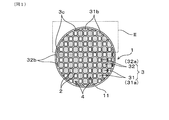
- FIG. 1 is an upstream end view showing a cell shape and closed cell arrangement of a honeycomb structure in Embodiment 1.
- FIG. 2 is an enlarged view of a main part of the upstream end view of the honeycomb structure according to the first embodiment, and is an enlarged view of a II part in FIG.
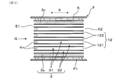
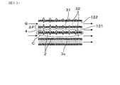
- FIG. 3 is an axial cross-sectional view of the honeycomb structure according to the first embodiment.
- FIG. 4 is a partially enlarged cross-sectional view of the honeycomb structure in the axial direction in Embodiment 1 and its both end views, FIG.
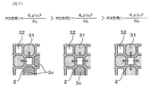
- FIG. 5 is an enlarged cross-sectional view of the main part in the axial direction of the honeycomb structure according to the first embodiment, and shows the gas flow from the adjacent through cell to the plugged cell in comparison with the conventional configuration having no closed cell.
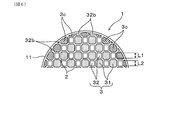
- Figure FIG. 6 is an enlarged view of the main part of the upstream end view showing the cell shape of the honeycomb structure and the closed cell arrangement in the second embodiment.
- FIG. 7 is a diagram for explaining the relationship between the presence / absence of a closed cell and the pressure in the cell in Embodiment 2, and is a partially enlarged sectional view in the axial direction of the honeycomb structure, FIG.
- FIG. 8 is an overall schematic configuration diagram showing an example of an exhaust gas purification apparatus for an internal combustion engine including an exhaust gas purification filter to which a honeycomb structure is applied in the first embodiment.
- FIG. 9 is an overall schematic configuration diagram showing another example of the exhaust gas purification apparatus for an internal combustion engine including the exhaust gas purification filter to which the honeycomb structure is applied in the first embodiment.
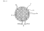
- FIG. 10 is an upstream end view showing the cell shape and closed cell arrangement of the honeycomb structure in Embodiment 3.
- FIG. 11 is a partially enlarged cross-sectional view in the axial direction of the honeycomb structure according to the third embodiment.
- FIG. 12 is an upstream end view showing the cell shape of the honeycomb structure and the closed cell arrangement in Embodiment 4.
- FIG. 13 is a partially enlarged cross-sectional view in the axial direction of the honeycomb structure showing a change in the wall permeation flow rate of the honeycomb structure having the closed cells in Test Example 1
- FIG. 14 is a partially enlarged cross-sectional view in the axial direction of the honeycomb structure showing a change in the wall permeation flow rate of the honeycomb structure having no closed cells in Test Example 1
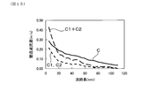
- FIG. 15 is a diagram showing the relationship between the substrate length and the wall permeation flow rate in the honeycomb structure having the closed cells and the honeycomb structure not having the closed cells in Test Example 1
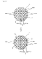
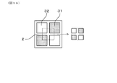
- FIG. 16 is a partially enlarged view of the upstream end face of the honeycomb structure for explaining the analysis range of the simulation in the test example
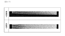
- FIG. 17 is a drawing-substituting photograph showing the axial sectional structure of the honeycomb structure of Example 2 and the particulate matter collection performance in comparison with the honeycomb structure of Comparative Example 1.
- the honeycomb structure 1 has a cylindrical shape as a whole, and has a cylindrical outer skin 11 having both ends open, and a porous cell wall 2 that partitions the cylindrical outer skin 11. And a large number of cells 3 surrounded by the cell wall 2.
- a large number of cells 3 form gas flow paths 12 extending in the axial direction X of the cylindrical outer skin 11.
- the honeycomb structure 1 has a single plug structure, and has plug portions 4 that alternately block a large number of cells 3 on the end surface on the upstream side (for example, the left end side in FIG. 3) of the gas flow path 12.
- the large number of cells 3 are divided into a plugged cell 31 having a plug portion 4 and a through cell 32 having no plug portion 4.
- the honeycomb structure 1 is surrounded by a cylindrical outer skin 11 and a cell wall 2 at the outermost peripheral part, and has a large number of incomplete cell cross-sectional shapes. It has an incomplete cell 3b.
- a large number of incomplete cells 3 b include incompletely plugged cells 31 b that are plugged cells 31 and through incomplete cells 32 b that are through cells 32.
- the entire cell 3a is a predetermined cell shape whose entire periphery is surrounded by the cell wall 2.
- the plugged cell 31 is a complete cell-shaped plugged cell (that is, the plugged complete cell 31a), and the through-cell 32 is a complete cell-shaped through-cell (that is, , Through-through complete cell 32a).
- the incomplete cell 3b is at least the plugged incomplete cell 31b of the plugged incomplete cell 31b, the cell cross sectional area A1 being smaller than the cell cross sectional area B of the penetrating complete cell 32a.
- the incompletely plugged cell 31b whose cell cross-sectional area A1 is equal to or larger than the cell cross-sectional area B of the penetrating complete cell 32a does not block the entire cell. Details of the closed cell 3c will be described later.
- the honeycomb structure 1 is disposed, for example, in the middle of an exhaust gas conduit of an internal combustion engine (not shown) as a filter base material of the exhaust gas purification filter F shown in FIG.
- the exhaust gas purification filter F is coaxially accommodated in a cylindrical case 5, and an exhaust gas G inlet 51 and an exhaust gas G outlet 52 are provided at both ends of the case 5.
- a cylindrical mat member F1 is interposed between the case 5 and the honeycomb structure 1.
- the internal combustion engine is, for example, a diesel engine or a gasoline engine for automobiles, and the exhaust gas purification filter F collects particulate matter in the exhaust gas G discharged to an exhaust gas pipe (not shown).
- a polygonal lattice-like cell wall 2 is disposed inside a cylindrical outer skin 11 having a circular cross section on the end face of the honeycomb structure 1, and a large number of cells 3 are , Having a polygonal cross-sectional shape.
- the cell shapes and cell cross-sectional areas of the large number of cells 3 may be the same or different. In this embodiment, it is composed of two types of cells having different cell shapes and cell cross-sectional areas, one of which is a plugged cell 31 and the other is a penetrating cell 32 which are arranged alternately.
- the penetrating cell 32 has, for example, a quadrangular cell shape
- the plugged cell 31 has a polygonal shape equal to or greater than a quadrangle, for example, an octagonal cell shape, and is disposed so as to surround each other.
- a quadrangle for example, an octagonal cell shape
- the cell cross-sectional area A of the plugged complete cell 31a and the cell cross-sectional area B of the penetrating complete cell 32a are set such that A ⁇ B.
- the plugging cell 31 is formed larger than the through-cell 32, and the cell cross-sectional area A of the octagonal cell forming the plugging cell 31 and the cell cross-sectional area B of the through-complete cell 32a are A> B Are in a relationship.
- the quadrangular cell forming the penetrating cell 32 has a smaller cell cross-sectional area than the octagonal cell forming the plugged cell 31.
- the quadrangular cells forming the penetrating cell 32 are, for example, all squares having the same length L2 on each side, and the plugging cell 31 includes four adjacent adjoining sides of the square penetrating cell 32.
- An octagonal cell shape having a long side and four short sides shorter than the length L1 of these long sides can be obtained.
- the plugging cell 31 is adjacent to the four penetrating cells 32 via the four long sides and is adjacent to the four plugging cells 31 via the four short sides arranged between the four long sides. All the octagonal cells forming the plugging cell 31 are plugged at the upstream end face to form the plug portion 4. At this time, not only a complete octagonal cell but also an incomplete octagonal cell in which a part of the octagon is missing, the plug portion 4 is formed and becomes an incompletely plugged cell 31b.
- gas flow paths 12 extending in the axial direction X are formed inside the large number of cells 3.
- the gas flow path 12 includes a plugged gas flow path 121 formed inside the plugged cell 31 and a through gas flow path 122 formed inside the through cell 32.
- the upstream end opens to the inlet 51 of the exhaust gas G and the downstream end opens to the outlet 52, and the exhaust gas G flows from the left to the right in the drawing.
- the plugging gas channel 121 is plugged at the upstream end, and only the downstream end opens to the outlet 52.
- the flow path length L in the axial direction X of the gas flow path 12 is equal to the axial length of the honeycomb structure 1, and the plugged gas flow path 121 has a shorter flow path length by the plugging length Pf of the plug portion 4. It has become. Further, the hydraulic diameter a of the plugging gas channel 121 is longer than the hydraulic diameter b of the through gas channel 122.
- the cell wall 2 of the honeycomb structure 1 is a porous wall made of a ceramic material, and pores formed therein communicate with each other, and the exhaust gas G flowing into the through gas flow path 122 is converted into a plugging gas flow. Permeate to the path 121 side. Then, the particulate matter contained in the exhaust gas G can be collected in the pores of the cell wall 2 while passing through the inside of the cell wall 2.
- a catalyst component can be supported on at least a part of the surface of the cell wall 2. For example, an oxidation catalyst may be supported to purify components such as CO and HC contained in the exhaust gas G. .
- the closed cell 3c will be described.
- closed cells 3c that are plugged over the entire length in the axial direction X are formed on the outermost peripheral portion of the honeycomb structure 1 at least for the incompletely plugged cells 31b.
- the honeycomb structure 1 includes an incompletely plugged cell 31b and an incompletely penetrating cell 32b inside the tubular outer shell 11, respectively.
- the plug incomplete cell has a cell cross sectional area A1 smaller than the cell cross sectional area B of the penetrating complete cell 32a among at least some of the incomplete plugged cells 31b.
- 31b is a blocked cell 3c in which the entire cell is blocked (that is, A1 ⁇ B).
- the closed cell 3 c can be formed using the same ceramic material as that of the plug portion 4.
- the exhaust gas G flows from the through cell 32 to the internal through gas flow path 122 at the upstream end face of the honeycomb structure 1.
- the upstream pressure in the plugging gas flow path 121 is higher than the pressure in the plugging gas flow path 121 where the exhaust gas G does not flow. Due to the pressure difference between the adjacent plugging gas channel 121 and the through gas channel 122, the exhaust gas G further passes through the porous cell wall 2 and flows into the adjacent plugging gas channel 121. At that time, particulate matter in the exhaust gas G is collected in the cell wall 2.
- the through gas flow path 122 is surrounded by the four plugged gas flow paths 122, and the exhaust gas G permeates the cell walls 2 in the four directions.
- the flow rate of the exhaust gas G decreases, and the differential pressure between adjacent cells decreases toward the downstream side, and the differential pressure becomes substantially zero at the downstream end face.
- the exhaust gas G does not pass through the cell wall 2 between the closed cell 3c and the cell wall 2 in the three directions. It will be transparent. In this case, even on the downstream side, the flow rate in the through gas flow path 122 does not decrease greatly, and the exhaust gas can permeate the cell wall 2 due to the differential pressure between adjacent cells.
- the gas permeation flow rate of the cell wall 2 is generated by the differential pressure of pipe friction between adjacent cells, and the theoretical formula of this differential pressure ⁇ P is generally expressed by the following formula 1.
- ⁇ P [(fL ⁇ (v 2 ) 2 / 2d 2 ] ⁇ [(fL ⁇ (v 1 ) 2 / 2d 1 ]
- f pipe friction coefficient
- L flow path length of gas flow path 12
- ⁇ exhaust gas density
- v 1 flow rate in plugging gas flow path 121
- v 2 flow speed in through gas flow path 122
- D 1 hydraulic diameter of the plugging gas passage 121
- d 2 hydraulic diameter of the through gas passage 122.
- Equation 1 From Equation 1, it can be seen that the differential pressure ⁇ P is proportional to the square of the flow velocity difference in the cell, and the differential pressure ⁇ P increases as the flow velocity in the through gas passage 122 increases. That is, by providing the closed cell 3c, it is possible to suppress the flow rate of the through gas flow path 122 from being greatly reduced and increase the gas permeation flow rate.
- the collection rate (unit: mass%) per honeycomb structure 1 can be expressed by the following formula 2.
- Collection rate 100 ⁇ [mass of collected particulate matter] / [mass of inflowing particulate matter]
- the differential pressure ⁇ P increases as the hydraulic diameter d 1 of the plugging gas flow path 121 is larger than the hydraulic diameter d 2 of the through gas flow path 122. That is, when the cell cross-sectional area A of the plugged complete cell 31a is larger than the cell cross-sectional area B of the penetrating complete cell 32a, the gas permeation flow rate increases and the effect of improving the collection rate is easily obtained.
- the flow rate of the exhaust gas G tends to be higher at the central portion of the honeycomb structure 1 and less at the outer peripheral portion of the honeycomb structure 1, so that the flow rate of the outer peripheral portion is maintained, so that efficient collection is achieved. It becomes possible and the effect of improving the collection rate is high.
- the ratio A / B of the cell cross-sectional area A of the plugged complete cell 31a and the cell cross-sectional area B of the penetrating complete cell 32a is set in the range of 1.1 to 5. .
- the ratio A / B is 1.1 or more, the differential pressure ⁇ P between the plugged cell 31 and the penetrating cell 32 can be increased to increase the collection rate.
- the cell cross-sectional area B of the penetrating complete cell 32a is relatively small, the pressure loss is likely to increase. Therefore, it is desirable to suppress the increase in pressure loss by setting the ratio A / B to 5 or less.
- the strength of the honeycomb structure 1 is relatively lowered, and handling at the time of storage in the case 51 (that is, canning) is possible. It becomes difficult. Even in such a case, since the outermost peripheral portion is reinforced by filling the incompletely plugged cell 31b, there is an advantage that the mechanical strength is increased and the canning property is improved.
- Embodiment 2 As shown in Embodiment 2 in FIG. 6, at the outermost periphery of the honeycomb structure 1, all of the plurality of incompletely plugged cells 31b are plugged over the entire length in the axial direction X, You can also That is, in addition to the incompletely plugged cell 31b where the cell cross-sectional area A1 is smaller than the cell cross-sectional area B of the through-through complete cell 32a, the cell cross-sectional area A1 is the same as the cell cross-sectional area B of the through-through complete cell 32a.
- the larger clogged cell 31b is also a closed cell 3c in which the entire cell is closed.
- the incomplete penetration cell 32b is left open at both ends.
- the cell side length of the large number of cells 3 is preferably such that the length L1 of the long side of the plugged cell 31 is equal to or longer than the length L2 of one side of the penetrating cell 32 (that is, L1 ⁇ L2).
- the cell wall 2 in contact with the through cell 32 is effectively used, gas permeation from the through cell 32 to the plugged cell 31 is promoted, and the collection rate can be further improved.
- the inner peripheral shape of the large number of cells 3 can be a polygonal corner having an R shape.
- the inner peripheral corner portion of the penetrating cell 32 may be formed in an R shape.
- the inner peripheral corner portion R of the plugged cell 31 is preferably larger than the inner peripheral corner portion R of the penetrating cell 32.
- the outer peripheral strength tends to decrease at a portion where the incompletely plugged cell 31b is present, which has a cell cross-sectional area A1 larger than that of the through-cell 32, but the strength against external pressure can be achieved by closing the entire portion. Will improve. Thereby, canning property improves more.
- the incompletely penetrated cells 32b may be the closed cells 3c. Also in this case, the mechanical strength is further improved as the number of closed cells 3c increases. However, since the incomplete penetrating cell 32b into which the exhaust gas G flows is blocked at the upstream end face of the honeycomb structure 1, the opening area on the upstream side of the honeycomb structure 1 is not reduced more than necessary.
- the incomplete penetrating cell 32b as the closed cell 3c may be appropriately selected as long as the desired exhaust gas flow rate and strength are compatible.
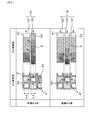
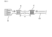
- an exhaust gas purification filter F including a honeycomb structure 1 having a single plug structure is disposed in the middle of an exhaust gas pipe E1 of an engine E, which is an internal combustion engine, and contains exhaust gas containing particulate matter.
- An exhaust gas purification device for purifying G is configured.
- the optimum configuration of the honeycomb structure 1 should be selected. Is desirable.
- the S / C catalyst 6 (that is, the start catalyst catalyst) is disposed upstream of the exhaust gas line E1, and the U / F position (that is, the vehicle floor downstream of the S / C catalyst 6)
- An exhaust gas purification filter F is disposed at the under floor position.
- the exhaust gas temperature is relatively low because the U / F position is downstream of, for example, a predetermined distance d (for example, 100 cm) from the S / C catalyst 6, and the exhaust gas purification filter F is heated and heated. Then, regeneration control for burning and removing the collected particulate matter is performed.
- the collection performance can be maintained by periodically heating and regenerating while improving the collection rate and strength of the exhaust gas purification filter F, and good regeneration efficiency can be obtained.
- the exhaust gas purification apparatus shown in FIG. 9 is a tandem type comprising a catalyst (for example, an oxidation catalyst or a three-way catalyst) 61 disposed upstream of the exhaust gas pipe E1 and an exhaust gas purification filter F disposed downstream thereof.
- a catalyst unit is provided.
- the catalyst 61 and the exhaust gas purification filter F are arranged close to each other, when the exhaust gas G flows from the catalyst 61 into the exhaust gas purification filter F in a high temperature state, the collected particulate matter can be spontaneously combusted. Is possible.
- the exhaust gas purification apparatus shown in FIG. 8 is also implemented, for example, by allowing the collected particulate matter to be spontaneously combusted by making the distance between the exhaust gas purification filter F and the S / C catalyst 6 shorter than 100 cm.
- the configuration of form 2 can also be adopted.
- the honeycomb structure 1 is configured by two types of cells 3 having different cell shapes and cell cross-sectional areas. However, as shown in the third embodiment in FIGS. It can also be constituted by one type of cell 3 having the same cell cross-sectional area.
- a large number of cells 3 constituting the honeycomb structure 1 are preferably polygonal, and here have a rectangular cell shape.
- plug portions 4 are arranged in a staggered manner on the upstream end face to form plugged cells 31, and the rest are penetrating cells 32.
- the hydraulic diameter a of the plugging gas channel 121 is equal to the hydraulic diameter b of the through gas channel 122.
- a plurality of incomplete cells 3b that is, incompletely plugged cells 31b and incompletely penetrated cells 32b are formed in the outermost peripheral portion of the honeycomb structure 1. .
- all the plugging incomplete cells 31b are plugged over the full length of the axial direction X, and let it be the obstruction
- the cell cross-sectional area A1 of the incompletely plugged cell 31b is always smaller than the cell cross-sectional area B of the penetrating complete cell 32a (that is, A1 ⁇ B).
- the incomplete penetration cell 32b is left open at both ends.
- the other configuration is the same as that of the first embodiment, and the description is omitted.
- the inter-cell differential pressure can be increased, and the particulate matter collection rate can be improved. Even if the cell cross-sectional area A of the plugged complete cell 31a and the cell cross-sectional area B of the penetrating complete cell 32a are the same, the cell difference is caused by the pressure difference between the plugged cell 31 having the plug portion 4 at the upstream end and the penetrating cell 32. The mechanism through which the exhaust gas G permeates the wall 2 is the same, and the pressure difference is maintained on the downstream side by the closed cell 3c.
- the entire honeycomb structure 1 can be effectively used to improve the collection rate. Moreover, the intensity
- Embodiment 4 As shown in FIG. 12 as Embodiment 4, in the honeycomb structure 1 of Embodiment 3, at least part of the incomplete penetrating cells 32b may be closed cells 3c.
- all the through incomplete cells 32b are the closed cells 3c.
- the through-complete cell 32b can be the closed cell 3c, and the mechanical strength increases with the increase of the closed cell 3c. Will improve.
- the other configuration is the same as that of the third embodiment, and the description is omitted.
- the inter-cell differential pressure can be further increased and the particulate matter collection rate can be improved.
- the outermost peripheral part of the honeycomb structure 1 since all the plugged incomplete cells 31b become the closed cells 3c, the strength against the external pressure is further improved, and the canning property is further improved.
- the honeycomb structure 1 having the above-described configuration can be manufactured by the following method. That is, the manufacturing method of the honeycomb structure 1 is as follows. Using an extrusion die having an extrusion groove having a shape corresponding to the cell wall 2 and the cylindrical outer skin 11, supplying a molding material of the honeycomb structure 1 to the extrusion groove, and extruding the honeycomb structure 1; On one end face side of the obtained honeycomb formed body, a plugging step of filling the plug 3 with the forming material of the plug portion 4 in the cells 3 to be plugged cells 31; In the incomplete cell 3b, a cell that becomes the closed cell 3c includes a plugging step that fills the entire material in the axial direction X with the forming material of the plug portion 4 simultaneously with the plugging step or after the plugging step.
- the extrusion mold used in the molding step can be a mold in which an extrusion groove portion corresponding to the honeycomb structure 1 to be manufactured is formed.
- the extrusion groove portion is composed of an annular groove formed in a portion corresponding to the cylindrical outer skin 11 and a polygonal lattice-like groove corresponding to a portion corresponding to the cell wall 2 inside thereof. It is formed so as to penetrate between both end faces.
- the honeycomb structure 1 in a state where all the cells 3 are penetrated can be obtained.
- the plugging cell 31 having the plug part 4 is formed by plugging the predetermined portion, and at least a part of the cell is filled with the material for forming the plug part 4 to form the plugged cell 3c. can do.
- the honeycomb structure 1 can be manufactured by changing the structure of the forming die without having the closing step. That is, Using an extrusion die having an extrusion groove having a shape corresponding to the cell wall 2 and the cylindrical outer skin 11, supplying a molding material of the honeycomb structure 1 to the extrusion groove, and extruding the honeycomb structure 1; A plugging step of filling the plug 3 with the forming material of the plug portion 4 in the cells 3 to be plugged cells 31 on one end face side of the obtained honeycomb formed body, The mold used in the molding process has an incomplete cell-shaped opening that penetrates between both end faces of the mold at a portion corresponding to the closed cell 3c in the extruded groove.
- the basic structure of the extrusion mold is the same as that of the above method, and the extrusion groove is formed in an annular groove formed in a portion corresponding to the cylindrical outer skin 11 and a portion corresponding to the cell wall 2 inside thereof. It consists of corresponding polygonal lattice grooves. Among them, for the portion corresponding to the closed cell 3c, the inner part surrounded by the groove is also an opening, and an opening corresponding to the shape of each closed cell 3c is formed. Thereby, in the molding step, the closed cell 3c is formed simultaneously with the extrusion molding. Thereafter, in the plugging process, the honeycomb structure 1 is obtained by forming the plug portions 4 in the portions corresponding to the plugged cells 31 for the completely shaped cells 3.
- Examples of the ceramic material used as the forming material of the honeycomb structure 1 include cordierite, silicon carbide, silicon-silicon carbide based composite material, mullite, alumina, spinel, silicon carbide-cordierite based composite material, lithium aluminum silicate, and aluminum titanate. At least one selected from the group consisting of is preferably used. Among these, cordierite having a small thermal expansion coefficient and excellent thermal shock resistance is preferable.
- the cordierite forming raw material is not particularly limited. For example, silica, talc, kaolin, calcined kaolin, alumina, aluminum hydroxide, magnesium hydroxide, etc., a plurality of ceramics that react with each other by firing to form cordierite. It is desirable to use raw materials.
- Such a ceramic raw material is mixed with a solvent such as water, a thickener, a dispersant and the like to obtain a molding material.
- a solvent such as water, a thickener, a dispersant and the like
- an organic binder, a pore former, a surfactant and the like can be added.
- the molding material thus adjusted to clay is kneaded to prepare clay.
- the obtained clay is formed into a honeycomb shape in the forming step.
- an extrusion mold produced to have a desired cell shape, cell wall thickness W, and cell density is used to extrude the kneaded material to obtain a honeycomb formed body.
- the cells 3 corresponding to the plugged cells 31 are plugged with the plug portion forming material that becomes the plug portions 4 on one end surface that becomes the inflow end surface of the honeycomb formed body.
- the plugged cell 31 can be plugged by masking the cell 3 to be the penetrating cell 32 in advance and immersing one end face in the plug forming material.
- the plug forming material is filled into the desired cell 3 as the plugged cell 3c in the plugging incomplete cell 31b at the outermost periphery.
- the plug portion forming material can be the same material as the ceramic material constituting the honeycomb structure 1.
- the filling method is not particularly limited, and, for example, a method of injecting a slurry-like plug portion forming material into a desired cell 3 from the inflow end surface side to the outflow end surface side of the desired cell 3 using a syringe or the like. Can be adopted. Or you may use the method of inject
- the extrusion mold may be devised so that the space between both end faces is completely filled at the time of extrusion molding. Thereby, a part or all of the incompletely plugged cell 31b can form the closed cell 3c plugged over the entire length in the axial direction X.
- the drying method is not particularly limited, and examples thereof include hot air drying, microwave drying, dielectric drying, reduced pressure drying, vacuum drying, and freeze drying. Among these, it is preferable to perform dielectric drying, microwave drying, or hot air drying alone or in combination.
- the drying conditions are preferably a drying temperature of 30 to 150 ° C. and a drying time of 1 minute to 2 hours.
- the firing temperature should just be more than the sintering temperature of the ceramic material used as the honeycomb structure 1, and can be suitably determined according to the ceramic material used.
- the firing temperature is preferably 1380 ° C. to 1450 ° C., more preferably 1400 ° C. to 1440 ° C.
- the firing time is preferably about 3 to 10 hours.
- the honeycomb structure 1 obtained in this way can adjust the porosity due to the pores inside the cell wall 2 by the pore former added to the ceramic material.
- the porosity of the cell wall 2 is not particularly limited, but is preferably 50% to 80%, and more preferably 55% to 70%, for example. If it is less than 50%, the collection performance may be remarkably deteriorated. If it is more than 80%, the strength of the honeycomb structure 1 is lowered, so that canning may be difficult. When the porosity is 55% to 70%, and more preferably 55% to 67%, the collection rate can be stably 35% by mass or more. Moreover, since the strength of the honeycomb structure 1 is also improved, canning is facilitated.
- the thickness of the cell wall 2 is not particularly limited, but is preferably, for example, 0.1 mm to 0.4 mm, and more preferably 0.12 mm to 0.38 mm. If the cell wall 2 is thinner than 0.1 mm, the strength of the honeycomb structure 1 may be reduced. If the cell wall 2 is thicker than 0.4 mm, the collection performance may be reduced and the pressure loss may be increased. Further, when the exhaust gas purification filter F is used for a diesel engine having a relatively large amount of PM in the exhaust gas G, the cell density usually tends to be reduced. Therefore, the thickness of the cell wall 2 is set to 0.20 to 0. .38 mm is preferable in order to improve the balance between strength and collection performance.
- the thickness of the cell wall 2 should be 0.12 to 0.30 mm. It is preferable for improving the balance of the collection performance.
- the thickness of the cell wall 2 can be measured by, for example, a method of observing a cross section in the axial direction X of the honeycomb structure 1 with a microscope.
- the cell density of the honeycomb structure 1 (that is, the number of cells per unit area in the cross section orthogonal to the axial direction X) is not particularly limited, but is, for example, 15 cells / cm 2 to 100 cells / cm 2. Is preferred. When it is less than 15 cells / cm 2 , the collection performance may be deteriorated, and when it is more than 100 cells / cm 2 , particulate matter may be deposited near the upstream end face, and pressure loss may be increased. Further, in the case of a diesel engine, it is more preferably 20 cells / cm 2 to 70 cells / cm 2 , and in the case of a gasoline engine, 30 cells / cm 2 to 100 cells / cm 2 . More preferably. Since the exhaust gas G discharged from the gasoline engine has a small amount of PM, the risk of the cells 3 being blocked is low, and the cell density can be increased to improve the collection performance.
- the average pore diameter of the cell wall 2 is not particularly limited, but is preferably 5 ⁇ m to 50 ⁇ m, for example, and more preferably 10 ⁇ m to 30 ⁇ m. If it is smaller than 5 ⁇ m, the pressure loss may increase even when the amount of particulate matter deposited is small. If it is larger than 50 ⁇ m, the honeycomb structure 1 tends to become brittle, and the particulate matter enters the cell walls 2. May result in depth filtration. When the average pore diameter of the partition walls is 10 ⁇ m or more, for example, even when an oxidation catalyst is supported, the permeation resistance when passing through the cell wall 2 is difficult to increase.
- the average pore diameter of the cell wall 2 can be measured by, for example, a mercury porosimeter.
- the cylindrical outer skin 11 and the plug portion 4 of the honeycomb structure 1 are also formed using a ceramic material.
- the thickness of the cylindrical outer skin 11 is not particularly limited, but is preferably 0.2 mm to 2 mm, for example. If it is thinner than 0.2 mm, cells near the outer periphery are likely to be chipped, and the strength may be lowered. If it is thicker than 2 mm, pressure loss may increase.
- the plugging length Pf of the plug portion 4 is not particularly limited, but is preferably 0.5 mm to 10 mm, for example. By setting the thickness to 0.5 mm or more, the upstream end face of the cell 3 can be sufficiently blocked, and by setting the thickness to 10 mm or less, an increase in the heat capacity is suppressed, and the regeneration efficiency when performing heating regeneration is maintained. Can do.
- the shape of the honeycomb structure 1 is not particularly limited, but a columnar shape, a columnar shape with an elliptical bottom surface, a polygonal columnar shape such as a square, pentagonal, hexagonal shape, or the like is preferable.
- the honeycomb structure 1 preferably has a column shape in which the extending direction of the cells 3 is the axial direction X.
- the size of the honeycomb structure 1 is not particularly limited, but the flow path length L of the gas flow path 12 formed in the cell 3 is preferably 40 mm to 200 mm.
- the flow path length L of the exhaust gas purification filter F is in this range, the exhaust gas G can be processed with excellent collection performance without increasing the pressure loss. If it is shorter than 40 mm, the collection performance is not sufficiently improved as compared with the conventional honeycomb structure, and the effect of the closed cell 3c in which the outermost peripheral incomplete cell 3b is completely filled may not be obtained. On the other hand, if it is longer than 200 mm, further improvement in the collection performance cannot be expected, but rather the pressure loss may increase.
- the flow path length L is more preferably 60 mm to 130 mm, and it is easy to obtain the effect of completely filling the outermost peripheral imperfect cell 3b to form the closed cell 3c.
- the relationship between the flow path length L, which is the axial length of the honeycomb structure 1, and the collection performance was examined as follows. About the base material model shown in FIGS. 13 and 14, the simulation is performed to analyze how the gas flow velocity flowing into the gas flow path 12 in the base material changes from the upstream side to the downstream side in the axial direction X. The results are shown in FIG.
- the substrate model of FIG. 13 is the honeycomb structure 1 having the closed cells 3c in the symmetrical cell structure of the third embodiment, and was compared with the substrate model of FIG. 14 having a conventional structure without the closed cells 3c.
- the analysis software is Star CCM + Vol. Using 10.02, the basic principle of calculation is based on the Naviestokes equation. The boundary conditions were as follows. ⁇ Mesh size: 0.5mm ⁇ Thickness layer thickness: 0.1mm ⁇ Frism layer: 2 -Number of meshes: 350,000
- each of two plugged cells 31 and penetrating cells 32 arranged alternately around the intersection of lattice-shaped cell walls 2 was used as an analysis range.
- one of the two plugged cells 31 is a closed cell 3c.
- the gas permeation to the plugged cell 31 side when the gas was introduced into the inlet side of the through-cell 32 under the following conditions was examined for the total length in the axial direction X.
- the wall permeate gas flow that permeates the cell wall 2 varies greatly depending on whether or not the through cell 32 is adjacent to the closed cell 3c.
- the through cell 32 adjacent to the closed cell 3c has no gas flow because one of the cell walls 2 located on both sides is on the closed cell 3c side, so that no PM flow occurs.
- Only the other cell wall 2 that is, the solid line: c in the figure
- the penetrating cell 32 has two cell walls 2 communicating with the plugging cell 31 on both sides thereof (that is, dotted lines: c1, c2 in the figure). Both contribute to PM collection, but the wall permeate gas flow becomes smaller toward the downstream side.
- the sum of the wall permeation flow speeds passing through the two cell walls 2 on both sides of the through-cell 32 (that is, the broken line in the figure: c1 + c2) is blocked.
- the wall permeation flow rate from the through cell 32 adjacent to the cell 3c to the plugged cell 31 side (that is, c in the figure) is exceeded.
- the difference between the two quickly shrinks and further reverses. For example, when the substrate length is 20 cm, the wall permeation flow rate is larger in the case of the closed cell 3 c than in the total of the two cell walls 2.
- the base material length is 40 cm
- the total amount of wall permeation gas from the upstream side is equal, and the longer the base material length is, the longer the base material length is, for example, 40 cm.
- the material length is 60 cm or more, the effect of the closed cell 3c is sufficiently large.
- the cordierite honeycomb structure 1 having the asymmetric cell structure of the second embodiment was manufactured by the above-described method, and an evaluation test was performed.
- the honeycomb structure 1 has a cylindrical shape with an outer diameter ⁇ : 130 mm ⁇ flow path length L: 100 mm, and has a single plug structure in which one end face side is closed with a plug portion 4.
- Example 1 the ratio A / B of the cell cross-sectional area of the octagonal plugged cell 31 to the square penetrating cell 32 was 1.05.
- the cell cross-sectional area A1 is smaller than the cell cross-sectional area B of the penetrating complete cell 32a (that is, the small cross-sectional area in the table) and equal to or greater than (ie, the large cross-section in the table).
- Both of the cells of area) were the closed cells 3c, and the honeycomb structure 1 was completely filled with the plug portion forming material. The specific method will be described next.
- a cordierite forming raw material was prepared by blending raw material powders such as silica, talc, kaolin, alumina, and aluminum hydroxide so as to have a cordierite composition.
- the cordierite forming raw material has a final composition after firing of SiO 2 : 47 to 53% by mass, Al 2 O 3 : 32% to 38% by mass, and MgO: 12% to 16% by mass.
- the raw material composition is adjusted and mixed with a solvent such as water, a thickener, a dispersant, etc., and adjusted to a clay, and as other additives, an organic binder, a pore former,
- the molding raw material to which a surfactant or the like was added was kneaded to form clay.
- the honeycomb formed body has an asymmetric cell structure composed of a quadrangular cell serving as the penetrating cell 32 and an octagonal cell serving as the plugging cell 31 shown in the first and second embodiments, and a lattice shape corresponding to the cell wall 2.
- extrusion was integrally performed.
- a plug forming material was prepared by blending the same raw material powder as described above so as to have a cordierite composition.
- This plug part forming material was added to a solvent such as water or oil, and stirred together with a thickener, a dispersant and the like using a mixer to uniformly disperse to form a slurry.
- a masking tape was applied to both end faces of the obtained honeycomb molded body, and then the masking tape was partially removed, so that openings were formed only in the cells that would become plugged cells 31 on the end faces.
- the removal of the masking tape is performed by, for example, laser beam irradiation, the laser irradiation device is disposed opposite to the end face of the honeycomb formed body, the irradiation position can be arbitrarily moved by the control device, and irradiation is performed sequentially.
- the masking tape corresponding to the cell to be plugged was removed.
- the plug portion forming material slurry was filled into the incomplete cells 3 b to be the closed cells 3 b.
- the plug portion forming material in the form of slurry was injected into all the incomplete plugging cells 31b from the inflow end surface side to the outflow end surface side of the honeycomb formed body.
- honeycomb formed body was dried and fired at 1400 ° C. to 1440 ° C.
- the honeycomb molded body and the plug portion forming material are sintered, the plug portions 4 are formed on one end surface, and all of the plugged incompletely plugged cells 31b are closed cells 3c.
- cordierite honeycomb structure 1 having the symmetrical cell structure of Embodiments 3 and 4 was produced.
- the cell shape both the plugged cell 31 and the penetrating cell 32 were square, and the cell cross-sectional area ratio A / B was 1.0.
- the honeycomb formed body was formed by the method of Example 1, and the plug portion 4 was formed on one end face thereof.
- the plug portion forming material was added to the honeycomb structure 1 (Example 2) in which all of the incompletely plugged cells 31b were filled into the closed cells 3c and the incompletely plugged cells 31b.
- the incomplete penetrating cell 32b was filled with the plug portion forming material, and a honeycomb structure 1 (Example 3) was obtained in which all the incomplete cells 3b were closed cells 3c. Furthermore, for comparison, a honeycomb structure in which the closed cells 3c are not formed in the incompletely plugged cells 31b was manufactured and used as Comparative Example 1.
- the honeycomb structure 1 of Examples 2 to 3 and Comparative Example 1 thus obtained was subjected to the following test to evaluate the particulate matter collection rate.
- the exhaust gas purification filter F containing the honeycomb structure 1 is attached to the exhaust gas pipe E1 of the gasoline engine E, and the exhaust gas G containing particulate matter is circulated through the exhaust gas purification filter F.
- the temperature was 700 ° C. and the flow rate was 4 m 3 / min.
- Table 1 shows the collection rate (unit: mass%) calculated based on Equation 2 described above, together with the measured value (unit: MPa) of isostatic strength and the heat capacity.
- the heat capacity is the heat capacity when the honeycomb structure 1 having a single plug filter structure in which only the plug portion 4 is formed is set to the reference value 1, and a predetermined part or all of the incomplete cells 3b are set to the closed cells 3c. It was evaluated in three stages from A to C according to the increase ratio.
- the honeycomb structure 1 of Comparative Example 1 having a symmetrical cell structure without the closed cells 3c has a trapping rate of 33% by mass and an isostatic strength of 0.85 MPa.
- the collection rate was improved to 39% by mass, and the isostatic strength was improved to 1.4 MPa.
- all the heat capacities were B determination, and the large fall of the heat capacity by the obstruction
- Example 3 in which all of the incomplete cells 3b were closed, the collection rate was the same as 39% by mass and the heat capacity was C evaluation, but the isostatic strength was further improved to 1.8 MPa. . Therefore, when the regeneration control is not performed, by adopting the configuration of Example 4, the honeycomb structure 1 with further improved canning property can be obtained.
- FIG. 17 shows a comparison of the effects of the presence or absence of the closed cells 3c, and in the honeycomb structure 1 of Example 2, the particulate matter is collected over the entire length up to the downstream side of the gas flow path 12.
- the honeycomb structure 1 of Comparative Example 1 the cell wall 2 on the downstream side of the gas flow path 12 does not contribute to the collection of the particulate matter, and the closed cell 3c prevents the particulate matter. It can be seen that the collection performance is greatly improved.
- Example 4 to 10 Comparative Examples 2 to 3
- Table 2 for the honeycomb structure 1 of Example 1, the honeycomb structure in which the ratio A / B of the cell cross-sectional area was changed and part or all of the incomplete cells 3b were closed cells 3c. 1 was prepared analogously (Examples 4 to 10).
- Honeycomb structure 1 (Example 5) in which cells having both small and large cross-sectional areas are closed cells 3c (Example 5), and honeycomb structure 1 (Example 6) in which all incomplete cells 3b are closed cells 3c Obtained.
- the honeycomb structure 1 (Example 7) in which the cell cross-sectional area ratio A / B was 5.0 and only the small cross-sectional area cells of the incompletely plugged cells 31b were closed cells 3c.
- a honeycomb structure 1 (Example 8) in which cells having both a small cross-sectional area and a large cross-sectional area are closed cells 3c (Example 8), and a honeycomb structure 1 (Example 9) in which all incomplete cells 3b are closed cells 3c. Obtained.
- Example 5 a honeycomb structure 1 having the same configuration as in Example 5 was manufactured except that the cell cross-sectional area ratio A / B was set to 5.2, and Example 10 was obtained. Furthermore, for comparison, a honeycomb structure 1 having the same configuration as in Examples 4 and 7 was manufactured except that the closed cells 3c were not formed in the incompletely plugged cells 31b, which were referred to as Comparative Examples 2 and 3, respectively.
- Example 2 For the honeycomb structures 1 of Examples 4 to 10 and Comparative Examples 2 to 3, the particulate matter collection rate, isostatic strength, and heat capacity were evaluated in the same manner as Example 1. Moreover, the increase in the pressure loss (henceforth a pressure loss) by setting it as an asymmetrical cell structure was evaluated as follows. The pressure loss is evaluated in three stages of A to C according to the increase rate of pressure loss when the ratio A / B of the cell cross-sectional area is increased with the reference value 1 in the case of a symmetric cell structure, and the results are also shown in Table 1. .
- the comparative example 2 having no closed cell 3c has an asymmetric cell structure, whereby the collection rate is improved to 39% by mass, but the isostatic strength is reduced to 0.8 MPa. Yes.
- the collection rate was improved to 44 mass% to 49 mass%, and the isostatic strength was 1.0 MPa to 1 MPa. It is improved to .8 MPa.
- Comparative Example 3 in which the cell cross-sectional area ratio A / B is further increased, the collection rate is improved to 58% by mass, but the isostatic strength is further reduced to 0.7 MPa.
- the collection rate is improved to 61 mass% to 66 mass%, and the isostatic strength is improved to 0.9 MPa to 1.7 MPa.
- the ratio A / B of the cell cross-sectional area of the honeycomb structure 1 is 1.1 or more, the effect of improving the collection rate due to the asymmetric cell structure is high.
- the cell cross-sectional area ratio A / B is preferably 1.
- both the collection rate and strength can be improved while suppressing an increase in pressure loss.
- isostatic strength is further improved by closing all incomplete cells 3b as in the sixth and ninth embodiments.
- the present disclosure is not limited to the above embodiments, and can be applied to various embodiments without departing from the scope of the disclosure.
- the honeycomb structure 1 having a single plug structure has been described as an example applied to an exhaust gas purification filter F for an automobile engine.
- the present invention is not necessarily limited to an automobile, and may be various internal combustion engines or other types. It can also be used for exhaust gas purification.
Landscapes
- Chemical & Material Sciences (AREA)
- Geometry (AREA)
- Physics & Mathematics (AREA)
- Engineering & Computer Science (AREA)
- Chemical Kinetics & Catalysis (AREA)
- Ceramic Engineering (AREA)
- Mechanical Engineering (AREA)
- Combustion & Propulsion (AREA)
- Manufacturing & Machinery (AREA)
- General Engineering & Computer Science (AREA)
- Structural Engineering (AREA)
- Health & Medical Sciences (AREA)
- Life Sciences & Earth Sciences (AREA)
- Geology (AREA)
- Materials Engineering (AREA)
- Organic Chemistry (AREA)
- Analytical Chemistry (AREA)
- Oil, Petroleum & Natural Gas (AREA)
- Toxicology (AREA)
- General Chemical & Material Sciences (AREA)
- Environmental & Geological Engineering (AREA)
- Biomedical Technology (AREA)
- Filtering Materials (AREA)
- Processes For Solid Components From Exhaust (AREA)
- Filtering Of Dispersed Particles In Gases (AREA)
- Exhaust Gas Treatment By Means Of Catalyst (AREA)
- Press-Shaping Or Shaping Using Conveyers (AREA)
- Catalysts (AREA)
Priority Applications (1)
| Application Number | Priority Date | Filing Date | Title |
|---|---|---|---|
| US16/337,520 US10905992B2 (en) | 2016-09-30 | 2017-09-26 | Honeycomb structural body, method for manufacturing the same, and exhaust gas purification filter |
Applications Claiming Priority (2)
| Application Number | Priority Date | Filing Date | Title |
|---|---|---|---|
| JP2016-192453 | 2016-09-30 | ||
| JP2016192453A JP6724697B2 (ja) | 2016-09-30 | 2016-09-30 | ハニカム構造体とその製造方法及び排ガス浄化フィルタ |
Publications (1)
| Publication Number | Publication Date |
|---|---|
| WO2018062186A1 true WO2018062186A1 (ja) | 2018-04-05 |
Family
ID=61760632
Family Applications (1)
| Application Number | Title | Priority Date | Filing Date |
|---|---|---|---|
| PCT/JP2017/034758 Ceased WO2018062186A1 (ja) | 2016-09-30 | 2017-09-26 | ハニカム構造体とその製造方法及び排ガス浄化フィルタ |
Country Status (3)
| Country | Link |
|---|---|
| US (1) | US10905992B2 (enExample) |
| JP (1) | JP6724697B2 (enExample) |
| WO (1) | WO2018062186A1 (enExample) |
Cited By (2)
| Publication number | Priority date | Publication date | Assignee | Title |
|---|---|---|---|---|
| WO2021033541A1 (ja) * | 2019-08-20 | 2021-02-25 | 株式会社デンソー | 排ガス浄化フィルタ |
| CN113039004A (zh) * | 2018-11-16 | 2021-06-25 | 康宁股份有限公司 | 具有不同水力直径的通道阵列的蜂窝体及其制造方法 |
Families Citing this family (2)
| Publication number | Priority date | Publication date | Assignee | Title |
|---|---|---|---|---|
| JP7354036B2 (ja) * | 2020-03-23 | 2023-10-02 | 日本碍子株式会社 | ハニカム構造体 |
| US12049429B2 (en) * | 2021-09-27 | 2024-07-30 | Corning Incorporated | Honeycomb body with a cutout portion and method of manufacturing same |
Citations (6)
| Publication number | Priority date | Publication date | Assignee | Title |
|---|---|---|---|---|
| JPH07246341A (ja) * | 1994-03-11 | 1995-09-26 | Ngk Insulators Ltd | セラミックハニカム構造体 |
| WO2008126692A1 (ja) * | 2007-03-27 | 2008-10-23 | Ngk Insulators, Ltd. | 目封止ハニカム構造体 |
| JP2012184660A (ja) * | 2011-03-03 | 2012-09-27 | Ngk Insulators Ltd | ハニカム構造体及び排ガス浄化装置 |
| US20140208946A1 (en) * | 2013-01-29 | 2014-07-31 | Corning Incorporated | Partial wall-flow filter and method |
| JP2015175359A (ja) * | 2014-03-18 | 2015-10-05 | 日本碍子株式会社 | 排ガス浄化装置 |
| JP2016130510A (ja) * | 2015-01-09 | 2016-07-21 | 株式会社デンソー | 排ガスフィルタ |
Family Cites Families (5)
| Publication number | Priority date | Publication date | Assignee | Title |
|---|---|---|---|---|
| JP5282030B2 (ja) * | 2007-03-27 | 2013-09-04 | 日本碍子株式会社 | 目封止ハニカム構造体 |
| WO2011117964A1 (ja) * | 2010-03-23 | 2011-09-29 | イビデン株式会社 | ハニカム構造体 |
| WO2011117965A1 (ja) * | 2010-03-23 | 2011-09-29 | イビデン株式会社 | ハニカム構造体 |
| JP2014181143A (ja) * | 2013-03-18 | 2014-09-29 | Ngk Insulators Ltd | ハニカム構造体 |
| JP6251078B2 (ja) * | 2014-02-25 | 2017-12-20 | 日本碍子株式会社 | ハニカム構造体 |
-
2016
- 2016-09-30 JP JP2016192453A patent/JP6724697B2/ja not_active Expired - Fee Related
-
2017
- 2017-09-26 WO PCT/JP2017/034758 patent/WO2018062186A1/ja not_active Ceased
- 2017-09-26 US US16/337,520 patent/US10905992B2/en not_active Expired - Fee Related
Patent Citations (6)
| Publication number | Priority date | Publication date | Assignee | Title |
|---|---|---|---|---|
| JPH07246341A (ja) * | 1994-03-11 | 1995-09-26 | Ngk Insulators Ltd | セラミックハニカム構造体 |
| WO2008126692A1 (ja) * | 2007-03-27 | 2008-10-23 | Ngk Insulators, Ltd. | 目封止ハニカム構造体 |
| JP2012184660A (ja) * | 2011-03-03 | 2012-09-27 | Ngk Insulators Ltd | ハニカム構造体及び排ガス浄化装置 |
| US20140208946A1 (en) * | 2013-01-29 | 2014-07-31 | Corning Incorporated | Partial wall-flow filter and method |
| JP2015175359A (ja) * | 2014-03-18 | 2015-10-05 | 日本碍子株式会社 | 排ガス浄化装置 |
| JP2016130510A (ja) * | 2015-01-09 | 2016-07-21 | 株式会社デンソー | 排ガスフィルタ |
Cited By (4)
| Publication number | Priority date | Publication date | Assignee | Title |
|---|---|---|---|---|
| CN113039004A (zh) * | 2018-11-16 | 2021-06-25 | 康宁股份有限公司 | 具有不同水力直径的通道阵列的蜂窝体及其制造方法 |
| WO2021033541A1 (ja) * | 2019-08-20 | 2021-02-25 | 株式会社デンソー | 排ガス浄化フィルタ |
| JP2021032096A (ja) * | 2019-08-20 | 2021-03-01 | 株式会社デンソー | 排ガス浄化フィルタ |
| JP6992790B2 (ja) | 2019-08-20 | 2022-02-03 | 株式会社デンソー | 排ガス浄化フィルタ |
Also Published As
| Publication number | Publication date |
|---|---|
| JP6724697B2 (ja) | 2020-07-15 |
| JP2018051500A (ja) | 2018-04-05 |
| US20190224606A1 (en) | 2019-07-25 |
| US10905992B2 (en) | 2021-02-02 |
Similar Documents
| Publication | Publication Date | Title |
|---|---|---|
| CN103140269B (zh) | 蜂窝过滤器及其制造方法 | |
| JP6068067B2 (ja) | 目封止ハニカム構造体 | |
| US8888883B2 (en) | Ceramic honeycomb structures | |
| JP5864329B2 (ja) | ハニカム構造体 | |
| JP6059936B2 (ja) | ハニカムフィルタ | |
| JP6110751B2 (ja) | 目封止ハニカム構造体 | |
| JP5997025B2 (ja) | ハニカム触媒体 | |
| JP6120709B2 (ja) | ハニカム触媒体 | |
| WO2018062186A1 (ja) | ハニカム構造体とその製造方法及び排ガス浄化フィルタ | |
| JP6110750B2 (ja) | 目封止ハニカム構造体 | |
| US10918988B2 (en) | Honeycomb filter | |
| US11058983B2 (en) | Honeycomb filter | |
| CN204563774U (zh) | 蜂窝结构体 | |
| JP6144946B2 (ja) | ハニカムフィルタ | |
| JP6485162B2 (ja) | 排ガス浄化フィルタ | |
| CN116892435A (zh) | 蜂窝过滤器 | |
| JP6091282B2 (ja) | 触媒コートフィルタ及び触媒コートフィルタ用担体 | |
| JP2023002191A (ja) | ハニカムフィルタ | |
| JP2008104944A (ja) | ハニカムフィルタ | |
| US10173163B2 (en) | Honeycomb structure | |
| JP6068219B2 (ja) | ハニカムフィルタ | |
| JP6530217B2 (ja) | ハニカム構造体 | |
| JP2017001234A (ja) | 押出成形用金型 |
Legal Events
| Date | Code | Title | Description |
|---|---|---|---|
| 121 | Ep: the epo has been informed by wipo that ep was designated in this application |
Ref document number: 17856136 Country of ref document: EP Kind code of ref document: A1 |
|
| NENP | Non-entry into the national phase |
Ref country code: DE |
|
| 122 | Ep: pct application non-entry in european phase |
Ref document number: 17856136 Country of ref document: EP Kind code of ref document: A1 |