WO2018055978A1 - 脱臭装置及び塗布装置 - Google Patents
脱臭装置及び塗布装置 Download PDFInfo
- Publication number
- WO2018055978A1 WO2018055978A1 PCT/JP2017/030448 JP2017030448W WO2018055978A1 WO 2018055978 A1 WO2018055978 A1 WO 2018055978A1 JP 2017030448 W JP2017030448 W JP 2017030448W WO 2018055978 A1 WO2018055978 A1 WO 2018055978A1
- Authority
- WO
- WIPO (PCT)
- Prior art keywords
- odor
- support frame
- deodorizer body
- substrate
- deodorizer
- Prior art date
- Legal status (The legal status is an assumption and is not a legal conclusion. Google has not performed a legal analysis and makes no representation as to the accuracy of the status listed.)
- Ceased
Links
Images




Classifications
-
- B—PERFORMING OPERATIONS; TRANSPORTING
- B01—PHYSICAL OR CHEMICAL PROCESSES OR APPARATUS IN GENERAL
- B01D—SEPARATION
- B01D53/00—Separation of gases or vapours; Recovering vapours of volatile solvents from gases; Chemical or biological purification of waste gases, e.g. engine exhaust gases, smoke, fumes, flue gases, aerosols
- B01D53/34—Chemical or biological purification of waste gases
- B01D53/74—General processes for purification of waste gases; Apparatus or devices specially adapted therefor
-
- B—PERFORMING OPERATIONS; TRANSPORTING
- B05—SPRAYING OR ATOMISING IN GENERAL; APPLYING FLUENT MATERIALS TO SURFACES, IN GENERAL
- B05C—APPARATUS FOR APPLYING FLUENT MATERIALS TO SURFACES, IN GENERAL
- B05C11/00—Component parts, details or accessories not specifically provided for in groups B05C1/00 - B05C9/00
- B05C11/10—Storage, supply or control of liquid or other fluent material; Recovery of excess liquid or other fluent material
-
- B—PERFORMING OPERATIONS; TRANSPORTING
- B05—SPRAYING OR ATOMISING IN GENERAL; APPLYING FLUENT MATERIALS TO SURFACES, IN GENERAL
- B05C—APPARATUS FOR APPLYING FLUENT MATERIALS TO SURFACES, IN GENERAL
- B05C15/00—Enclosures for apparatus; Booths
-
- B—PERFORMING OPERATIONS; TRANSPORTING
- B05—SPRAYING OR ATOMISING IN GENERAL; APPLYING FLUENT MATERIALS TO SURFACES, IN GENERAL
- B05C—APPARATUS FOR APPLYING FLUENT MATERIALS TO SURFACES, IN GENERAL
- B05C21/00—Accessories or implements for use in connection with applying liquids or other fluent materials to surfaces, not provided for in groups B05C1/00 - B05C19/00
Definitions
- the present invention relates to a deodorizing apparatus provided in a waste liquid tray of a coating apparatus that forms a coating film on a substrate, and can suppress dust generation due to rubbing of a pipe that circulates odor and improve durability. And a coating device provided with the deodorizing device.
- a substrate such as a coating substrate
- a coating solution such as a resist solution is coated on a substrate such as glass
- the coating substrate is formed by a coating apparatus that applies a coating solution.
- the coating apparatus includes a stage 110 on which the substrate W is placed, and an applicator 100 that ejects a coating solution from a slit extending in one direction on the placed substrate W.
- a coating film is formed on the substrate W by relatively moving the substrate W while discharging the coating liquid from the container 100 (see, for example, Patent Document 1).
- the coating apparatus is generally provided with a maintenance device 101 so that the discharge state of the applicator 100 can be kept constant.
- the maintenance device 101 includes a cleaning device 102 and a waste liquid tray 103 that receives waste liquid (see FIG. 8).
- the maintenance device 101 reaches the coating device 100. It moves and is positioned so that the applicator 100 is positioned on the waste liquid tray 103. Then, when the cleaning device 102 moves along the slit of the applicator 100, the coating liquid adhering to the slit is wiped off, and the excess coating liquid wiped off falls on the waste liquid tray 103 and is collected.
- the waste liquid tray 103 is filled with odor because a solvent such as a cleaning liquid for cleaning the cleaning device 102 is stored for a long time in addition to an unnecessary coating liquid. Therefore, a deodorizing device 104 is installed in the waste liquid tray 103 so that odors filling the waste liquid tray 103 are exhausted. Specifically, as shown in FIG. 8, the deodorizing device 104 is provided adjacent to the waste liquid tray 103, and a deodorizer body 105 and a traveling device 106 that is common to the maintenance device 101 (waste liquid tray 103). , And an odor piping portion 107 for distributing odor from the deodorizer body 105, and the odor piping portion 107 is connected to an exhaust suction source (not shown).
- the deodorizer body 105 is formed with an odor suction port 108 that opens to the waste liquid tray 103 side, and is formed so that a suction force from the exhaust suction source is generated at the odor suction port 108 through the odor pipe portion 107. .
- the odor filling the waste liquid tray 103 is sucked from the odor suction port 108 and exhausted to the exhaust suction source through the odor pipe portion 107.
- the odor piping portion 107 is provided with an extra length bent in a U-shape, so that the deodorizer body 105 can follow even when the maintenance device 101 moves to the position of the applicator 100, and the traveling device 106 travels. At the same time, it is formed so that odor can be sucked.
- the deodorizing apparatus 104 has a problem in durability of the odor pipe 107 and a problem that particles are generated during traveling. That is, since the odor pipe portion 107 is bent in a U shape, the bent state changes due to the movement of the deodorizer body 105 accompanying the maintenance device 101. Therefore, in addition to the deterioration due to the bending of the odor pipe being accelerated by long-term operation, there is a problem that particles may be generated due to the odor pipe section 107 contacting and rubbing with other members (for example, the traveling device 106). there were.
- the odor pipe 107 may be accommodated in the cable bear (registered trademark). To accommodate the odor pipe 107 in the cable bear (registered trademark), the odor pipe 107 is used. There is a problem that the amount of odor sucked from the odor suction port 108 cannot be increased.
- the present invention provides a deodorizing device capable of suppressing dust generation due to rubbing of an odor pipe portion through which an odor is circulated without reducing the amount of odor, and improving durability, and a coating device including the deodorizing device.
- the purpose is to provide.
- a deodorizing apparatus of the present invention and a coating apparatus equipped with the deodorizing apparatus discharge a coating liquid from a coating device to a substrate transported to a stage surface to form a coating film on the substrate.
- a deodorizing device provided in the coating device to be formed which is provided so as to be movable in the substrate transport direction with respect to the applicator, and a deodorizer main body for deodorizing the odor of the waste liquid tray storing the waste liquid of the applicator;
- a duct portion, and the joint duct portion is configured to allow the deodorizer body and the support frame to communicate with each other, and the joint duct portion to be rotatable about an axis perpendicular to the stage surface.
- the support frame portion is provided with a differential absorption guide portion that allows the rotation support
- the deodorizer body and the support frame portion are connected by the joint duct portion, and the support frame portion is provided with the swing support portion.
- the joint duct part follows the deodorizer body.
- the differential absorption guide part is provided in the turning support part, when the deodorizer body moves from the state farthest from the support frame part and approaches the support frame part, the deodorizer body and the support frame part (swing support)
- the difference absorption guide part allows the swivel support part to be displaced in a direction perpendicular to the moving direction of the deodorizer body, so that the swivel support part of the deodorizer body and the support frame part is reduced.
- the distance between and can be kept constant. That is, the connected state can be maintained with the joint duct portion having a constant length.
- the length of the joint duct part can be kept constant regardless of the position of the deodorizer body, so that the joint duct part (equivalent to a conventional odor pipe) has a U-shape to provide extra length. There is no need to bend. Therefore, the durability of the joint duct portion can be improved and dust generation due to rubbing of the joint duct portion can be suppressed. Further, since it is not necessary to use a cable bear (registered trademark) and the installation space of the joint duct part is not limited, it is possible to avoid a decrease in odor amount due to a reduction in the diameter of the joint duct part.
- the communication duct part of the joint duct part may be configured by a straight pipe member having no posture change.
- joint duct portion may contain a pipe through which a liquid or gas flows.
- FIG. 1 is a perspective view schematically showing a coating apparatus 2 combined with the deodorizing apparatus of the present invention
- FIG. 2 is a front view of the coating apparatus 2 in FIG.
- the coating apparatus 2 includes a substrate transport apparatus 1 that transports a substrate W and a coating unit 21, and forms a coating film on the substrate W transported to the substrate transport apparatus 1. is there. That is, the coating film is formed on the substrate W by discharging the coating liquid from the coating unit 21 while transporting the substrate W by the substrate transport apparatus 1.
- the direction in which the substrate W is transported is the X-axis direction
- the X-axis direction corresponds to the transport direction.
- the direction orthogonal to the X-axis direction on the horizontal plane is defined as the Y-axis direction
- the Y-axis direction is also referred to as the river width direction.
- the description will be made with the direction orthogonal to both the X-axis direction and the Y-axis direction as the Z-axis direction.
- the application unit 21 applies a coating solution to the substrate W, and includes a frame portion 22 and an applicator 23.
- the frame portion 22 has support columns 22a arranged on both sides in the Y-axis direction of the levitation stage unit 10, and an applicator 23 is provided on the support column 22a.
- the support columns 22a are fixedly provided on both sides in the Y-axis direction (river width direction), so that the travel of the substrate holding unit 30 to be described later is prevented from being hindered. Is also arranged on the outside.
- the applicator 23 is spanned over these support
- the support 22a is provided with a lifting mechanism, and the applicator 23 can move in the Z direction by operating the lifting mechanism. That is, the applicator 23 can be moved toward and away from the floating stage unit 10 by the lifting mechanism.
- the applicator 23 is for discharging the coating liquid and is formed extending in one direction.
- the applicator 23 is formed with a slit nozzle 23a (see FIG. 2) extending in one direction so that the application liquid stored in the applicator 23 can be discharged from the slit nozzle 23a.
- the slit nozzle 23a is formed on a surface facing the levitation stage unit 10, and the applicator 23 is installed in a state where the slit nozzle 23a extends in the river width direction.
- the coating liquid is ejected from the slit nozzle 23a.
- a uniform coating film is continuously formed in the transport direction.
- a coating film having a uniform thickness is formed on the substrate W by moving the substrate W while discharging the coating liquid from the slit nozzle 23a.
- the substrate transport apparatus 1 transports the substrate W in one direction (in this embodiment, the X-axis direction, also referred to as the substrate transport direction) while floating.
- the substrate transport apparatus 1 includes a levitation stage unit 10 that floats the substrate W, and a substrate transport unit 3 that holds and transports the substrate W levitated on the levitation stage unit 10.
- the levitation stage unit 10 levitates the substrate W, and has an air levitation mechanism in the present embodiment.
- the levitation stage unit 10 is formed by providing a flat plate portion 12 on a base 11, and is formed by arranging a plurality of flat plate portions 12 along the X-axis direction. That is, the flat plate portion 12 has a smooth stage surface 12a (see FIG. 1), and the respective stage surfaces 12a are arranged so as to have a uniform height. An air layer is formed between the stage surface 12a and the substrate W to be transported, so that the substrate W can be floated to a predetermined height position.
- the flat plate portion 12 is formed with a fine jet port (not shown) and a suction port (not shown) that open to the stage surface 12a, and the jet port and the compressor are connected by piping, The suction port and the vacuum pump are connected by piping.
- the substrate W can be floated in a horizontal posture at a predetermined height from the stage surface 12a by balancing the air ejected from the ejection port and the suction force generated at the suction port. As a result, the substrate W can be transported in a state in which the planar posture (referred to as flatness) is maintained with high accuracy.
- the flat plate portion 12 of the floating stage portion 10 is formed so that its Y-axis direction dimension is smaller than the Y-axis direction dimension of the substrate W to be transported, and when the substrate W is placed on the stage surface 12a, the stage surface The end of the substrate W in the Y-axis direction protrudes from 12a.
- the protruding portion is held by a substrate transfer unit 3 described later, so that the substrate W can be transferred.
- the substrate transport unit 3 transports the floating substrate W, and includes a substrate holding unit 30 that holds the substrate W and a transport drive unit 31 that travels the substrate holding unit 30.
- the transport driving unit 31 is configured to move the substrate holding unit 30 in the transport direction, and includes a transport rail unit 31a that extends in the transport direction along the floating stage unit 10, and a base that travels on the transport rail unit 31a. It is formed with the part 31b. Specifically, bases 31c (see FIG. 2) provided so as to extend in the transport direction are disposed on both sides in the river width direction of the levitation stage unit 10, and transport rails 31a are provided on the respective bases 31c. It has been. That is, the conveyance rail part 31a is continuously provided along the levitation stage part 10 without interruption.
- the base portion 31b is a plate-like member formed in a concave shape, and is provided so as to cover the upper surface of the transport rail portion 31a, for example, as shown in FIG.
- the base portion 31b is provided so as to cover the transport rail portion 31a via an air pad, and the base portion 31b travels on the transport rail portion 31a by driving a linear motor (not shown). Yes. That is, by driving and controlling the linear motor, the base portion 31b can travel without contacting the transport rail portion 31a and can be stopped at a predetermined position.
- a substrate holding unit 30 is provided in the base portion 31b, and the substrate W is sucked and held by the substrate holding unit 30. That is, by driving and controlling the linear motor while the substrate W is attracted to the substrate holding unit 30, the substrate W can be moved along the floating stage unit 10 and can be stopped at a predetermined position. It has become.
- the coating device 2 is provided with a maintenance device 4 so that the applicator 23 can be appropriately maintained.
- the maintenance device 4 includes a cleaning device 41 and a waste liquid tray 42 and is provided on the floating stage unit 10.
- the waste liquid tray 42 has a shape extending in one direction, and is disposed so as to cross the floating stage unit 10 in the Y-axis direction.
- the waste liquid tray 42 has a shape capable of storing liquid, and is formed in a shape that is slightly larger than the applicator 23. That is, the waste liquid tray 42 is formed so as to receive a waste liquid such as a cleaning liquid and an excess coating liquid when the applicator 23 is disposed on the waste liquid tray 42 and a cleaning operation is performed by the cleaning device 41. .
- the waste liquid tray 42 is provided with a cleaning device 41.
- the cleaning device 41 is for cleaning the coating liquid adhering to the applicator 23.
- the cleaning device 41 has a cleaning block 42 a having a V-shaped groove, and the cleaning block 42 a is formed to be able to travel in the longitudinal direction of the waste liquid tray 42.
- a scraping member that contacts the slit nozzle 23a is provided in the V-shaped groove of the cleaning block 42a, and the cleaning liquid is discharged into the V-shaped groove. That is, in a state where the slit nozzle 23a is disposed in the V-shaped groove of the cleaning block 42a, the scraping member comes into contact with the side surface of the slit nozzle 23a.
- the scraping member is attached to the side surface of the slit nozzle 23a by moving in the longitudinal direction of the slit nozzle 23a while being in contact with the side surface of the slit nozzle 23a.
- the coating solution is softened with a cleaning solution and scraped off.
- the applicator 23 can be mechanically cleaned by the cleaning device 41.
- the scraped coating liquid and cleaning liquid fall onto the waste liquid tray 42, are temporarily stored in the waste liquid tray 42, and are finally discharged to the outside.
- the maintenance device 4 is provided with a traveling device 5 so that the maintenance device 4 can move in the direction of transporting the substrate W.
- the travel rail portion 51 that extends in the transport direction along the floating stage portion 10 and the travel base portion 52 that travels on the travel rail portion 51 are formed. Yes.
- the traveling rail portion 51 is disposed outside the conveyance rail portion 31 a on the base 31 c, and the traveling rail portion 51 is continuously provided along the floating stage portion 10.
- a traveling base portion 52 is provided via an air pad so as to cover the upper surface of the traveling rail portion 51, and the traveling base portion 52 moves over the traveling rail portion 51 by a linear motor (not shown). It is configured to run.
- the traveling base unit 52 can travel on the traveling rail unit 51 and stop at a predetermined position.
- the traveling base unit 52 is set so as to be able to stop at the maintenance position and the standby position. That is, at the maintenance position, the maintenance device 4 moves so that the waste liquid tray 42 of the maintenance device 4 is positioned directly below the applicator 23, and at the standby position, the maintenance device 4 moves to a predetermined location away from the maintenance position. Is set to
- the maintenance device 4 is provided with a deodorizing device 6, which deodorizes by sucking odor generated by a solvent such as cleaning liquid and coating liquid stored in the waste liquid tray 42. It is.
- the deodorizer 6 includes a deodorizer body 61 that deodorizes odors, a support frame portion 62 having an exhaust suction source, and a joint duct portion 63 that connects the deodorizer body 61 and the support frame portion 62. A suction force from the exhaust suction source is generated in the deodorizer body 61 through the joint duct portion 63, so that the odor of the waste liquid tray 42 is deodorized from the deodorizer body 61.
- the deodorizer main body 61 has a suction opening 61a for sucking odor, and is provided adjacent to the waste liquid tray 42 so that the suction opening 61a faces the waste liquid tray 42.
- the deodorizer main body 61 has a rectangular parallelepiped shape, and is integrally provided adjacent to the waste liquid tray 42. That is, the deodorizer main body 61 is fixed to the waste liquid tray 42, and the deodorizer main body 61 moves together with the waste liquid tray 42 when the maintenance device 4 moves.
- a suction opening 61a is provided on the wall surface 61b in contact with the waste liquid tray 42. In the present embodiment, five suction openings 61a are provided. In the example shown in FIG. 4, the suction openings 61 a are provided side by side in one direction (Y-axis direction) at a predetermined height position from the waste liquid tray 42.
- the suction force from the exhaust suction source is supplied to the deodorizer body 61 through the joint duct portion 63.
- a joint duct portion 63 is connected to both ends of the deodorizer body 61 in the Y-axis direction, and suction force from an exhaust suction source is supplied through the joint duct portion 63.
- two suction hoses 64 are connected to the joint duct portion 63, and a suction force is generated from the suction opening 61a through the suction hose 64. That is, the deodorizer body 61 is formed with a manifold portion 61c communicating with all the suction openings 61a, and four suction hoses 64 are connected to the manifold portion 61c.
- the suction hose 64 when a suction force is generated from the suction hose 64, a suction force is generated in the entire manifold portion 61c, and a suction force is generated from each suction opening 61a.
- the suction force supplied from the suction hose 64 increases in the vicinity of the suction hose 64.
- the suction hose 64 is connected to the manifold portion 61c so as to be arranged substantially evenly in the Y-axis direction, whereby the suction force supplied from the suction hose 64 becomes uniform in the Y-axis direction.
- the suction force becomes uniform over the entire manifold portion 61c. Therefore, the suction force generated in each suction opening 61a becomes uniform, and the odor generated from the waste tray can be sucked evenly over the entire waste tray.
- the support frame part 62 is a support
- FIG. The support frame 62 is fixed to the deodorizer body 61 and is fixed to the floor of a factory.
- the exhaust suction source provided in a factory is accommodated in the inside of the support frame part 62 of this embodiment, and the odor suck
- the upper surface portion 62a of the support frame portion 62 is formed in a planar shape, and the joint duct portion 63 is connected to the upper surface portion 62a.
- a differential absorption guide portion 7 (see FIG. 3) described later is provided on the upper surface portion 62 a of the support frame portion 62, and is connected to the flat plate block portion 71 of the differential absorption guide portion 7.
- the joint duct portion 63 connects the deodorizer body 61 and the support frame portion 62, and guides the odor sucked from the deodorizer body 61 to the exhaust suction source. That is, the joint duct part 63 distributes the odor sucked from the deodorizer body 61 to the support frame part 62 and exhausts the odor from the exhaust supply source of the support frame part 62.
- the joint duct portion 63 includes a communication duct portion 63a and turning support portions 63b arranged at both ends thereof.
- the communication duct portion 63a is formed of a pipe member extending in one direction, and connects the deodorizer body 61 and the support frame portion 62 in communication with each other via the turning support portion 63b.
- the communication duct portion 63a is made of a material with little posture change, and is made of stainless steel in the present embodiment. That is, there is no bending change like a resin tube member or a plastic tube, and the posture of connecting the deodorizer body 61 and the support frame portion 62 can be maintained. Thereby, problems such as rubbing due to contact with other members due to posture changes, deterioration due to bending, and the like can be avoided.
- the turning support portion 63b supports the communication duct portion 63a so as to be rotatable around an axis perpendicular to the stage surface 12a of the levitation stage portion 10 (in the present embodiment, around the Z axis).
- the turning support parts 63 b are provided at both ends of the communication duct part 63 a, and the end parts are connected to the support frame part 62.
- the swivel support portion 63b uses a swivel joint and has a fixed portion 63b1 extending in one direction and a swivel portion 63b2 formed in an L shape (see FIG. 3).
- the fixing portion 63b1 is connected to the deodorizer body 61 or the support frame portion 62
- the turning portion 63b2 is connected to the communication duct portion 63a.
- the fixed portion 63b1 of the turning support portion 63b is connected to the deodorizer body 61 or the other or the support frame portion 62 in a posture extending in the Z-axis direction, and one end of the turning portion 63b2 is connected to the fixed portion 63b1.
- the turning part 63b2 has a shape extending from the one end side in the Z-axis direction along the direction in which the fixing part 63b1 extends and extending 90 degrees in the middle.
- the turning support part 63b supports the communication duct part 63a so as to be rotatable around an axis perpendicular to the stage surface 12a of the levitation stage part 10 (around the center axis of the fixed part 63b1).
- the deodorizer body 61 when the maintenance device 4 is moved from the maintenance position to the standby position, the deodorizer body 61 is also moved accordingly, so that the deodorizer body 61 is moved in the substrate transport direction with respect to the support frame portion 62. It moves to the upstream side and the downstream side in the substrate transport direction.
- the turning portion 63b2 of the turning support portion 63b on the support frame portion 62 side rotates with respect to the fixed portion 63b1, so that one end portion of the turning portion 63b2 (the side connected to the communication duct portion 63a) is deodorized. It can always face the main body 61.
- the turning portion 63b2 of the turning support portion 63b on the deodorizer body 61 side rotates with respect to the fixed portion 63b1
- one end portion of the turning portion 63b2 (side connected to the communication duct portion 63a) is the support frame. It is possible to always face the portion 62.
- the maintenance device 4 deodorizer body 61
- the swivel portion 63b2 of the swivel support portion 63b rotates, so that the joint duct portion 63 deodorizes without changing its dimensions.
- the main body 61 can be followed.
- the differential absorption guide part 7 is provided in the turning support part 63b provided in the support frame part 62 (see FIG. 3).
- the differential absorption guide portion 7 allows the turning support portion 63b to be displaced in a direction orthogonal to the movement of the deodorizer body 61.
- the differential absorption guide portion 7 is provided on the upper surface portion 62 a of the support frame portion 62, and has a guide rail portion 72 and a flat plate block portion 71. That is, a guide rail portion 72 extending in one direction is installed on the upper surface portion 62a of the support frame portion 62 in a direction (Y axis direction) orthogonal to the transport direction (X axis direction) of the substrate W. 72 is formed so that the flat plate block 71 can move.
- the flat block part 71 when the flat block part 71 receives force in the X-axis direction, it is adjusted so that it can move on the guide rail part 72 smoothly. And the fixed part 63b1 of the turning support part 63b is attached to the flat block part 71, and the position of the turning support part 63b can be displaced to a Y-axis direction. As a result, the distance between the deodorizer body 61 and the turning support portion 63b of the support frame portion 62 can be kept constant regardless of the position of the deodorizer body 61 in the transport direction.
- the deodorizer main body 61 (maintenance device 4) is disposed at the standby position, and the communication duct portion 63 a of the joint duct portion 63 is at the standby position positioned upstream in the transport direction of the substrate W. It is installed in an extended state.
- the turning support part 63b on the support frame part 62 is disposed at a position close to the floating stage part 10 (FIG. 6A).
- the deodorizer body 61 (maintenance device 4) moves to the maintenance position directly below the applicator 23 in order to complete the application operation and perform the maintenance operation.
- the deodorizer main body 61 moves to the downstream side in the transport direction of the substrate W, so that the position of the swivel support portion 63 b of the deodorizer main body 61 and the swivel portion 63 b 2 of the support frame portion 62. Try to be close to each other.
- the communication duct part 63a is formed with stainless steel, when the turning support parts 63b try to come close to each other, a load is applied to the turning support part 63b as much as they approach, but the flat plate block part 71 of the differential absorption guide part 7 Receives the force with which the swivel support portions 63b try to approach each other, and moves to a position away from the levitation stage portion 10. That is, the turning support part 63b on the support frame part 62 moves to a position away from the floating stage part 10 in the Y-axis direction, and the distance between the turning support parts 63b is kept constant (FIG. 6B).
- the turning support parts 63b are now separated from each other, so that the turning support part 63b receives a tensile force from the communication duct part 63a. Therefore, when the flat plate block portion 71 of the differential absorption guide portion 7 moves to the levitation stage portion 10 side, the distance between the turning support portions 63b is kept constant (FIG. 6 (c)).
- the joint support portion 63 follows the deodorizer body 61 by turning the turning support portion 63b.
- the difference absorption guide part 7 is provided in the turning support part 63b, when the deodorizer body 61 moves from the state farthest from the support frame part 62 and approaches the support frame part 62, the deodorizer body 61 and Although the distance to the support frame portion 62 (the turning support portion 63b) is shortened, the difference absorption guide portion 7 allows the turning support portion 63b to be displaced in a direction orthogonal to the moving direction of the deodorizer body 61.
- the distance between the deodorizer body 61 and the turning support portion 63b of the support frame portion 62 can be kept constant. That is, the connected state can be maintained with the joint duct portion 63 having a constant length.
- the joint duct part 63 (corresponding to a conventional odor pipe) has a surplus length as in the past. There is no need to bend in a U-shape. Therefore, the durability of the joint duct portion 63 can be improved, and dust generation due to rubbing of the joint duct portion 63 can be suppressed.
- it is not necessary to use a cable bear (registered trademark) and the installation space of the joint duct part 63 is not limited, it is possible to avoid a decrease in odor amount due to the diameter reduction of the joint duct part 63.
- any pipe member that does not change in posture may be used.
- a pipe member made of metal such as aluminum can be used.
- a change in posture such as bending deformation causes friction or deterioration due to contact with other members. The problem can be avoided.
- the joint duct part 63 is used as an odor pipe
- the said embodiment demonstrated the case where the board
Landscapes
- Engineering & Computer Science (AREA)
- Environmental & Geological Engineering (AREA)
- Chemical & Material Sciences (AREA)
- Health & Medical Sciences (AREA)
- Biomedical Technology (AREA)
- Analytical Chemistry (AREA)
- General Chemical & Material Sciences (AREA)
- Oil, Petroleum & Natural Gas (AREA)
- Chemical Kinetics & Catalysis (AREA)
- Coating Apparatus (AREA)
Abstract
臭気量を低下させることなく、臭気を流通させる臭気配管部の擦れによる発塵を抑え、耐久性を向上させることができる脱臭装置及びその脱臭装置を備えた塗布装置を提供する。具体的には、ステージ面に搬送された基板に塗布膜を形成する塗布装置に設けられる脱臭装置であって、塗布器に対して移動可能に設けられ、廃液トレイの臭気を脱臭する脱臭器本体と、排気吸引源を有する支持フレーム部と、脱臭器本体と支持フレーム部とを連結し、前記脱臭器本体の臭気を排気吸引源に導くジョイントダクト部と、を有しており、ジョイントダクト部は、脱臭器本体と支持フレームとを連結する連通ダクト部と、連通ダクト部をステージ面に垂直な軸周りに回転可能に支持する旋回支持部とを有しており、支持フレーム部には、旋回支持部が脱臭器本体の移動方向と直交する方向に変位することを許容する差分吸収ガイド部が設けられている構成とする。
Description
本発明は、基板上に塗布膜を形成する塗布装置の廃液トレイに設けられる脱臭装置に関するものであり、臭気を流通させる配管の擦れによる発塵を抑え、耐久性を向上させることができる脱臭装置、及び、その脱臭装置を備えた塗布装置に関するものである。
液晶ディスプレイやプラズマディスプレイ等のフラットパネルディスプレイには、ガラス等の基板上にレジスト液等の塗布液が塗布されたもの(塗布基板という)が使用されている。この塗布基板は、塗布液を塗布する塗布装置によって形成されている。塗布装置は、図7に示すように、基板Wを載置するステージ110と、載置された基板Wに一方向に延びるスリットから塗布液を吐出する塗布器100とを有しており、塗布器100から塗布液を吐出させながら、基板Wを相対的に移動させることにより、基板W上に塗布膜が形成されるようになっている(例えば特許文献1参照)。
また、塗布装置は、一般に、メンテナンス装置101が設けられており、塗布器100の吐出状態を一定に保つことができるようになっている。このメンテナンス装置101には、清掃装置102と、廃液を受ける廃液トレイ103が設けられており(図8参照)、基板Wに塗布膜を形成する塗布動作を完了するとメンテナンス装置101が塗布器100まで移動し、廃液トレイ103上に塗布器100が位置するように位置決めされる。そして、清掃装置102が塗布器100のスリットに沿って移動することによりスリットに付着した塗布液が拭き取られ、拭き取られた余分な塗布液は、廃液トレイ103に落下して回収される。
この廃液トレイ103には、不要な塗布液に加え、清掃装置102を洗浄するための洗浄液等の溶剤が長時間貯留されるため臭気が充満する。そのため、廃液トレイ103には、脱臭装置104が設置されており、廃液トレイ103に充満する臭気が排気されるようになっている。具体的には、図8に示すように、脱臭装置104は、廃液トレイ103に隣接して設けられており、脱臭器本体105と、メンテナンス装置101(廃液トレイ103)と共通の走行装置106と、脱臭器本体105から臭気を流通させる臭気配管部107とを有しており、臭気配管部107は排気吸引源(不図示)に接続されている。脱臭器本体105には、廃液トレイ103側に開口する臭気吸引口108が形成されており、排気吸引源からの吸引力が臭気配管部107を通じて臭気吸引口108に発生するように形成されている。これにより、廃液トレイ103に充満する臭気は、臭気吸引口108から吸引され、臭気配管部107を通じて排気吸引源に排気されるようになっている。ここで、臭気配管部107は、U字に曲げた余長分が設けられており、メンテナンス装置101が塗布器100の位置まで移動しても脱臭器本体105が追従でき、走行装置106の走行とともに常に臭気を吸引できるように形成されている。
しかし、上記脱臭装置104では、臭気配管部107の耐久性に問題があり、また、走行中にパーティクルが発生するという問題があった。すなわち、臭気配管部107は、U字状に屈曲させて設けられているため、メンテナンス装置101に伴う脱臭器本体105の移動により屈曲状態が変化する。そのため、長期運転により臭気配管の屈曲による劣化が早まることに加え、臭気配管部107が他の部材(例えば、走行装置106)と接触して擦れることにより、パーティクルが発生する虞があるという問題があった。
また、他の部材との接触を防止するため、臭気配管部107をケーブルベア(登録商標)内に収容することも考えられるが、ケーブルベア(登録商標)内に収容するには臭気配管部107を小径にする必要があり、臭気吸引口108から吸引する臭気量を大きくすることができないという問題があった。
そこで、本発明は、臭気量を低下させることなく、臭気を流通させる臭気配管部の擦れによる発塵を抑え、耐久性を向上させることができる脱臭装置、及び、その脱臭装置を備えた塗布装置を提供することを目的としている。
上記課題を解決するために本発明の脱臭装置、及び、その脱臭装置を備えた塗布装置は、ステージ面に搬送された基板に対して塗布器から塗布液を吐出して基板上に塗布膜を形成する塗布装置に設けられる脱臭装置であって、前記塗布器に対して基板の搬送方向に移動可能に設けられ、前記塗布器の廃液を貯留する廃液トレイの臭気を脱臭する脱臭器本体と、前記脱臭器本体に対して固定して設けられ、排気吸引源を有する支持フレーム部と、前記脱臭器本体と前記支持フレーム部とを連結し、前記脱臭器本体の臭気を排気吸引源に導くジョイントダクト部と、を有しており、前記ジョイントダクト部は、前記脱臭器本体と前記支持フレームとを連通させる連通ダクト部と、前記連通ダクト部を前記ステージ面に垂直な軸周りに回転可能に支持する旋回支持部とを有しており、前記支持フレーム部には、前記旋回支持部が前記脱臭器本体の移動方向と直交する方向に変位することを許容する差分吸収ガイド部が設けられていることを特徴としている。
本発明によれば、脱臭器本体と、支持フレーム部とがジョイントダクト部で連結され、支持フレーム部に旋回支持部が設けられていることにより、脱臭器本体がメンテナンス装置とともに移動すると、旋回支持部が旋回することによりジョイントダクト部が脱臭器本体に追従する。また、旋回支持部には、差分吸収ガイド部が設けられているため、脱臭器本体が支持フレーム部から最も離れた状態から移動し支持フレーム部に接近すると脱臭器本体と支持フレーム部(旋回支持部)との距離が短くなるが、差分吸収ガイド部により旋回支持部が脱臭器本体の移動方向と直交する方向に変位することが許容されるため、脱臭器本体と支持フレーム部の旋回支持部との距離を一定に保つことができる。すなわち、ジョイントダクト部が長さを一定にした状態で連結状態を維持することができる。これにより、脱臭器本体がどの位置であってもジョイントダクト部の長さを一定できるため、従来のようにジョイントダクト部(従来の臭気配管に相当)に余長を持たせるためにU字状に屈曲させる必要がない。したがって、ジョイントダクト部の耐久性を向上させ、ジョイントダクト部の擦れによる発塵を抑えることができる。また、ケーブルベア(登録商標)を用いる必要がなくジョイントダクト部の設置スペースも限定されないことから、ジョイントダクト部の小径化による臭気量の低下を回避することができる。
また、前記ジョイントダクト部の連通ダクト部は、姿勢変化のない直線状の管部材で形成されている構成にしてもよい。
この構成によれば、姿勢変化のない(剛性の高い)金属製(例えば、ステンレス、アルミ等)の管部材を使用することができるため、樹脂製などで形成された管部材に比べて、姿勢変化による他の部材との接触による擦れ、撓みによる劣化等の問題を回避することができる。
また、前記ジョイントダクト部には、液体又は気体が流通する配管が収容されている構成にしてもよい。
この構成によれば、廃液トレイを含むメンテナンス装置に必要な液配管、エア配管等を収容することができ、別途ケーブルベア(登録商標)等の配管案内機構が不要になる。
本発明によれば、臭気量を低下させることなく、臭気を流通させる臭気配管部の擦れによる発塵を抑え、耐久性を向上させることができる。
以下、本発明の脱臭装置に係る実施の形態について図面を用いて説明する。
図1は、本発明の脱臭装置と組み合わされる塗布装置2を概略的に示す斜視図であり、図2は、図1における塗布装置2の正面図である。
図1、図2において、塗布装置2は、基板Wを搬送する基板搬送装置1と塗布ユニット21とを有しており、基板搬送装置1に搬送された基板Wに塗布膜を形成するものである。すなわち、基板搬送装置1で基板Wを搬送させつつ、塗布ユニット21から塗布液を吐出することにより基板W上に塗布膜が形成されるようになっている。
以下の説明では、基板Wが搬送される方向をX軸方向とし、X軸方向が搬送方向に相当する。また、X軸方向と水平面上で直交する方向をY軸方向とし、特にY軸方向を川幅方向ともいう。そして、X軸方向及びY軸方向の双方に直交する方向をZ軸方向として説明を進めることとする。
塗布ユニット21は、基板Wに塗布液を塗布するものであり、フレーム部22と塗布器23とを有している。フレーム部22は、浮上ステージ部10のY軸方向両側にそれぞれ配置される支柱22aを有しており、この支柱22aに塗布器23が設けられている。具体的には、支柱22aは、Y軸方向(川幅方向)両側に固定して設けられており、後述する基板保持部30の走行を妨げることのないように、基板保持部30の走行経路よりも外側に配置されている。そして、これらの支柱22aに塗布器23が架け渡されており、塗布器23が浮上ステージ部10を横切る状態で取り付けられている。また、支柱22aには昇降機構が設けられており、昇降機構を作動させることにより塗布器23がZ方向に移動できるようになっている。すなわち、昇降機構により塗布器23が浮上ステージ部10に対して接離動作できるようになっている。
塗布器23は、塗布液を吐出するものであり、一方向に延びて形成されている。この塗布器23は、一方向に延びるスリットノズル23a(図2参照)が形成されており、塗布器23内に貯留された塗布液をスリットノズル23aから吐出できるようになっている。具体的には、スリットノズル23aは、浮上ステージ部10と対向する面に形成されており、塗布器23はスリットノズル23aが川幅方向に延びる状態で設置されている。そして、搬送される基板Wに対して塗布器23を昇降させて基板Wとスリットノズル23aとの距離を所定の距離に合わせた状態で、スリットノズル23aから塗布液を吐出することにより、川幅方向に一様な塗布膜が搬送方向に連続的に形成されるようになっている。そして、スリットノズル23aから塗布液を吐出させつつ、基板Wを移動させることにより、基板W上には、均一厚さの塗布膜が形成されるようになっている。
また、基板搬送装置1は、基板Wを浮上させつつ、一方向(本実施形態ではX軸方向、基板搬送方向ともいう)に搬送させるものである。基板搬送装置1は、基板Wを浮上させる浮上ステージ部10と、浮上ステージ部10に浮上させた基板Wを保持し搬送させる基板搬送ユニット3とを有している。
浮上ステージ部10は、基板Wを浮上させるものであり、本実施形態ではエア浮上機構を有している。浮上ステージ部10は、基台11上に平板部12が設けられて形成されており、複数枚の平板部12がX軸方向に沿って配列されて形成されている。すなわち、平板部12は、平滑なステージ面12a(図1参照)を有しており、それぞれのステージ面12aが均一高さになるように配列されている。そして、ステージ面12aには、搬送させる基板Wとの間に空気層が形成されることにより基板Wを所定高さ位置に浮上させることができるようになっている。具体的には、平板部12には、ステージ面12aに開口する微小な噴出口(不図示)と吸引口(不図示)とが形成されており、噴出口とコンプレッサとが配管で接続され、吸引口と真空ポンプとが配管で接続されている。そして、噴出口から噴出されるエアと吸引口に発生する吸引力とをバランスさせることにより、基板Wがステージ面12aから所定高さに水平の姿勢で浮上させることができるようになっている。これにより、基板Wの平面姿勢(平面度という)を高精度に維持した状態で搬送できる
ようになっている。
ようになっている。
また、浮上ステージ部10の平板部12は、そのY軸方向寸法が搬送される基板WのY軸方向寸法よりも小さく形成されており、ステージ面12a上に基板Wを載置すると、ステージ面12aから基板WのY軸方向端部がはみ出した状態となる。このはみ出した部分を後述の基板搬送ユニット3で保持することにより、基板Wを搬送できるようになっている。
また、基板搬送ユニット3は、浮上状態の基板Wを搬送させるものであり、基板Wを保持する基板保持ユニット30と、基板保持ユニット30を走行させる搬送駆動部31とを有している。
搬送駆動部31は、基板保持ユニット30を搬送方向に移動させるように構成されており、浮上ステージ部10に沿って搬送方向に延びる搬送レール部31aと、この搬送レール部31a上を走行するベース部31bとで形成されている。具体的には、搬送方向に延びるように設けられた基台31c(図2参照)が浮上ステージ部10の川幅方向両側に配置されており、それぞれの基台31c上に搬送レール部31aが設けられている。すなわち、搬送レール部31aが浮上ステージ部10に沿って途切れることなく連続して設けられている。また、ベース部31bは、凹形状に形成された板状部材であり、例えば図2に示すように、搬送レール部31aの上面を覆うように設けられている。ベース部31bは、エアパッドを介して搬送レール部31aに覆うように設けられており、リニアモータ(不図示)を駆動させることにより、ベース部31bが搬送レール部31a上を走行するようになっている。すなわち、リニアモータを駆動制御することにより、ベース部31bが搬送レール部31a上を接触することなく走行し、所定の位置で停止できるようになっている。
また、ベース部31bには、基板保持ユニット30が設けられており、この基板保持ユニット30により基板Wが吸着保持されるようになっている。すなわち、基板保持ユニット30に基板Wを吸着させた状態でリニアモータを駆動制御することにより、基板Wを浮上ステージ部10に沿って移動させることができ、所定の位置で停止させることができるようになっている。
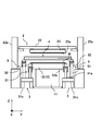
また、塗布装置2には、メンテナンス装置4が設けられており、塗布器23を適切に保つことができるようになっている。メンテナンス装置4は、図4に示すように、清掃装置41と廃液トレイ42を有しており、浮上ステージ部10上に設けられている。
廃液トレイ42は、一方向に延びる形状を有しており、浮上ステージ部10をY軸方向に横切るように配置されている。廃液トレイ42は、液体を貯留できる形状を有しており、塗布器23よりも一回り大きい形状に形成されている。すなわち、廃液トレイ42は、廃液トレイ42上に塗布器23が配置され清掃装置41による清掃動作が行われた場合に、洗浄液、及び、余分な塗布液等の廃液を受けるように形成されている。
廃液トレイ42には、清掃装置41が設けられている。この清掃装置41は、塗布器23に付着した塗布液を洗浄するものである。具体的には、清掃装置41は、V字溝を有する洗浄ブロック42aを有しており、この洗浄ブロック42aが廃液トレイ42の長手方向に走行できるように形成されている。また、洗浄ブロック42aのV字溝内には、スリットノズル23aに接触する掻き取り部材が設けられており、さらにV字溝内に洗浄液が吐出されるようになっている。すなわち、洗浄ブロック42aのV字溝にスリットノズル23aが配置された状態では、掻き取り部材がスリットノズル23aの側面に接触するようになっている。この状態で、洗浄液を吐出しつつ洗浄ブロック42aを走行させると、掻き取り部材がスリットノズル23aの側面に接触しつつスリットノズル23aの長手方向に移動することにより、スリットノズル23aの側面に付着した塗布液が洗浄液で軟化され掻き取られる。これにより、清掃装置41により塗布器23が機械的に清掃できるようになっている。そして、掻き取られた塗布液、及び、洗浄液は廃液トレイ42に落下し、廃液トレイ42で一時的に貯留され、最終的に外部に排出されるようになっている。
また、メンテナンス装置4には、走行装置5が設けられており、メンテナンス装置4が基板Wの搬送方向に移動できるようになっている。本実施形態では、図2,図3に示すように、浮上ステージ部10に沿って搬送方向に延びる走行レール部51と、この走行レール部51上を走行する走行ベース部52とで形成されている。具体的には、走行レール部51が基台31c上の搬送レール部31aの外側に配置され、この走行レール部51が浮上ステージ部10に沿って連続して設けられている。そして、走行レール部51上には、走行ベース部52が走行レール部51の上面を覆うようにエアパッドを介して設けられ、リニアモータ(不図示)により走行ベース部52が走行レール部51上を走行するように形成されている。すなわち、リニアモータを駆動制御することにより、走行ベース部52が走行レール部51上を走行し、所定の位置で停止できるようになっている。本実施形態では、走行ベース部52は、メンテナンス位置と待機位置とに停止できるように設定されている。すなわち、メンテナンス位置では、メンテナンス装置4の廃液トレイ42が塗布器23直下に位置するようにメンテナンス装置4が移動し、待機位置では、メンテナンス装置4がメンテナンス位置から離れた所定の場所に移動するように設定されている。
また、図4に示すように、メンテナンス装置4には、脱臭装置6が設けられており、廃液トレイ42に貯留される洗浄液、塗布液等の溶剤が発生する臭気を吸引することにより脱臭するものである。脱臭装置6は、臭気を脱臭する脱臭器本体61と、排気吸引源を有する支持フレーム部62と、脱臭器本体61と支持フレーム部62とを連結するジョイントダクト部63とを有しており、排気吸引源からの吸引力がジョイントダクト部63を通じて脱臭器本体61に発生させることにより、廃液トレイ42の臭気が脱臭器本体61から脱臭されるように形成されている。
脱臭器本体61は、臭気を吸引する吸引開口部61aを有しており、吸引開口部61aが廃液トレイ42上に臨むように廃液トレイ42と隣接して設けられている。具体的には、脱臭器本体61は、直方体形状を有しており、廃液トレイ42と隣接して一体的に設けられている。すなわち、脱臭器本体61は廃液トレイ42に固定されており、メンテナンス装置4が移動すると脱臭器本体61が廃液トレイ42と供に移動するようになっている。そして、廃液トレイ42と接する壁面61bには、吸引開口部61aが設けられており、本実施形態では、5つの吸引開口部61aが設けられている。図4に示す例では、吸引開口部61aは、廃液トレイ42から所定の高さ位置に一方向(Y軸方向)に並んで設けられている。
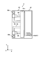
脱臭器本体61には、ジョイントダクト部63を通じて排気吸引源からの吸引力が供給される。脱臭器本体61のY軸方向両端部には、ジョイントダクト部63が連結されており、このジョイントダクト部63を通じて排気吸引源からの吸引力が供給されるようになっている。具体的には、ジョイントダクト部63には2本の吸引ホース64(図5参照)が接続されており、この吸引ホース64を通じて吸引開口部61aから吸引力が発生する。すなわち、脱臭器本体61には、すべての吸引開口部61aと連通するマニホールド部61cが形成されており、マニホールド部61cには4つの吸引ホース64が接続されている。これにより、吸引ホース64から吸引力が発生するとマニホールド部61c全体に吸引力が発生し、それぞれの吸引開口部61aから吸引力が発生するようになっている。ここで、吸引ホース64から供給される吸引力は、吸引ホース64付近では強くなる。そのため、吸引ホース64がマニホールド部61cに対してY軸方向にほぼ均等に並んで接続されることにより、吸引ホース64から供給される吸引力がY軸方向に亘って均一になり、さらにマニホールド部61cで集合させることにより、吸引力がマニホールド部61c全体に亘って均一になる。したがって、それぞれの吸引開口部61aに発生する吸引力が均一になり、廃棄トレイから発生する臭気を廃棄トレイ全体に亘って偏りなく吸引できるようになっている。
また、支持フレーム部62は、支柱部材であり、浮上ステージ部10の両側に1つずつ設置されている。この支持フレーム部62は、脱臭器本体61に対して固定して設けられており、工場の床面に固定して設けられている。そして、本実施形態の支持フレーム部62の内部には、工場に設けられる排気吸引源が収容されており、脱臭器本体61から吸引された臭気が排気吸引源を通じて排気される。すなわち、排気吸引源とジョイントダクト部63とが接続されており、脱臭器本体61から吸引された臭気がジョイントダクト部63を通じて排気吸引源から排気されるようになっている。ここで、支持フレーム部62の上面部62aは、平面状に形成されており、この上面部62aにジョイントダクト部63が接続されている。具体的には、支持フレーム部62の上面部62aには、後述する差分吸収ガイド部7(図3参照)が設けられており、差分吸収ガイド部7の平板ブロック部71に連結されている。
ジョイントダクト部63は、脱臭器本体61と支持フレーム部62とを連結するものであり、脱臭器本体61から吸引した臭気を排気吸引源に導くものである。すなわち、ジョイントダクト部63は、脱臭器本体61から吸引された臭気を支持フレーム部62に流通させ、臭気を支持フレーム部62の排気供給源から排気させる。このジョイントダクト部63は、連通ダクト部63aと、その両端に配置される旋回支持部63bとを有している。
連通ダクト部63aは、一方向に延びる管部材で形成されており、旋回支持部63bを介して脱臭器本体61と支持フレーム部62とを連通させて接続するものである。この連通ダクト部63aは、姿勢変化の少ない材料で形成されており、本実施形態ではステンレスで形成されている。すなわち、樹脂製の管部材やプラスチック製のチューブのような撓み変化がなく、脱臭器本体61と支持フレーム部62とを連結する姿勢を保つことができるように形成されている。これにより、姿勢変化による他の部材との接触による擦れ、撓みによる劣化等の問題を回避することができる。
旋回支持部63bは、連通ダクト部63aを浮上ステージ部10のステージ面12aに垂直な軸周り(本実施形態ではZ軸周り)に回転可能に支持するものである。旋回支持部63bは、連通ダクト部63aの両端部に設けられており、端部が支持フレーム部62に連結されている。この旋回支持部63bは、スイベルジョイントが用いられており、一方向に延びる形状の固定部63b1と、L字状に形成される旋回部63b2とを有している(図3参照)。本実施形態では、固定部63b1が脱臭器本体61、又は、支持フレーム部62に連結され、旋回部63b2が連通ダクト部63aに連結されている。
旋回支持部63bの固定部63b1は、Z軸方向に延びる姿勢で、脱臭器本体61、他又は、支持フレーム部62に連結されており、旋回部63b2は、その一方端が固定部63b1に対して中心軸周りに回転可能に接続されている。すなわち、旋回部63b2は、一方端側から固定部63b1の延びる方向に沿ってZ軸方向に延び、途中で90度向きを変えて延びる形状を有している。そして、旋回部63b2を固定部63b1に対して回転させると、旋回部63b2の他方端が固定部63b1の中心軸から一定距離離れた位置で外径側を向く姿勢で回転する。すなわち、旋回支持部63bは、連通ダクト部63aを浮上ステージ部10のステージ面12aに垂直な軸周り(固定部63b1の中心軸周り)に回転可能に支持している。これにより、脱臭器本体61が基板Wの搬送方向に移動しても、ジョイントダクト部63が脱臭器本体61に追従することができる。すなわち、図6に示すように、メンテナンス装置4がメンテナンス位置から待機位置に移動すると、それに伴って脱臭器本体61も移動することにより、支持フレーム部62に対して脱臭器本体61が基板搬送方向上流側及び基板搬送方向下流側に移動する。このとき、支持フレーム部62側の旋回支持部63bの旋回部63b2が固定部63b1に対して回転することにより、旋回部63b2の一方端部(連通ダクト部63aと連結される側)が脱臭器本体61に常に対向することができる。同様に、脱臭器本体61側の旋回支持部63bの旋回部63b2が固定部63b1に対して回転することにより、旋回部63b2の一方端部(連通ダクト部63aと連結される側)が支持フレーム部62に常に対向することができる。このように、メンテナンス装置4(脱臭器本体61)が基板Wの搬送方向に移動するに従って、旋回支持部63bの旋回部63b2が回転することにより、ジョイントダクト部63がその寸法を変えることなく脱臭器本体61に追従することができる。
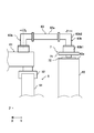
また、支持フレーム部62に設けられる旋回支持部63bには、差分吸収ガイド部7が設けられている(図3参照)。この差分吸収ガイド部7は、旋回支持部63bが脱臭器本体61の移動と直交する方向に変位することを許容するものである。この差分吸収ガイド部7は、支持フレーム部62の上面部62aに設けられており、ガイドレール部72と平板ブロック部71とを有している。すなわち、支持フレーム部62の上面部62aに、一方向に延びるガイドレール部72が基板Wの搬送方向(X軸方向)と直交する方向(Y軸方向)に設置されており、このガイドレール部72上を平板ブロック部71が移動できるように形成されている。本実施形態では、平板ブロック部71がX軸方向に力を受けると、スムーズにガイドレール部72上を移動できるように調節されている。そして、平板ブロック部71には、旋回支持部63bの固定部63b1が取り付けられており、旋回支持部63bの位置をY軸方向に変位できるようになっている。これにより、脱臭器本体61が搬送方向のどの位置にあっても、脱臭器本体61と支持フレーム部62の旋回支持部63bとの距離を一定に保つことができる。
すなわち、図6に示すように、脱臭器本体61(メンテナンス装置4)が待機位置に配置されており、ジョイントダクト部63の連通ダクト部63aが基板Wの搬送方向上流側に位置する待機位置に延びた状態で設置されている。この場合、支持フレーム部62上の旋回支持部63bは、浮上ステージ部10に近い位置に配置されている(図6(a))。
そして、塗布動作が完了しメンテナンス動作を行うために、脱臭器本体61(メンテナンス装置4)が塗布器23直下のメンテナンス位置に移動する。脱臭器本体61が基板Wの搬送方向下流側に移動すると、脱臭器本体61が支持フレーム部62に近づくため、脱臭器本体61の旋回支持部63bの位置と、支持フレーム部62の旋回部63b2の位置が互いに近接しようとする。そして、連通ダクト部63aがステンレスで形成されているため、旋回支持部63b同士が近接しようとすると、近接した分だけ旋回支持部63bに負荷がかかるが、差分吸収ガイド部7の平板ブロック部71が旋回支持部63b同士が近接しようとする力を受け、浮上ステージ部10から離れた位置に移動する。すなわち、支持フレーム部62上の旋回支持部63bが浮上ステージ部10からY軸方向に離れた位置に移動し旋回支持部63b同士の距離が一定に保たれる(図6(b))。そして、脱臭器本体61がさらに搬送方向下流側に移動すると、今度は旋回支持部63b同士が離れようとするため、旋回支持部63bは連通ダクト部63aから引張力を受ける。そのため、差分吸収ガイド部7の平板ブロック部71が浮上ステージ部10側に移動することにより、旋回支持部63b同士の距離が一定に保たれる(図6(c))。
このように、上記実施形態によれば、脱臭器本体61がメンテナンス装置4とともに移動すると、旋回支持部63bが旋回することによりジョイントダクト部63が脱臭器本体61に追従する。そして、旋回支持部63bには、差分吸収ガイド部7が設けられているため、脱臭器本体61が支持フレーム部62から最も離れた状態から移動し支持フレーム部62に接近すると脱臭器本体61と支持フレーム部62(旋回支持部63b)との距離が短くなるが、差分吸収ガイド部7により旋回支持部63bが脱臭器本体61の移動方向と直交する方向に変位することが許容されるため、脱臭器本体61と支持フレーム部62の旋回支持部63bとの距離を一定に保つことができる。すなわち、ジョイントダクト部63が長さを一定にした状態で連結状態を維持することができる。これにより、脱臭器本体61がどの位置であってもジョイントダクト部63の長さを一定できるため、従来のようにジョイントダクト部63(従来の臭気配管に相当)に余長を持たせるためにU字状に屈曲させる必要がない。したがって、ジョイントダクト部63の耐久性を向上させ、ジョイントダクト部63の擦れによる発塵を抑えることができる。また、ケーブルベア(登録商標)を用いる必要がなくジョイントダクト部63の設置スペースも限定されないことから、ジョイントダクト部63の小径化による臭気量の低下を回避することができる。
また、上記実施形態では、連通ダクト部63aにステンレス製の管部材を使用する例について説明したが、姿勢変化のない(剛性の高い)管部材であればよい。例えば、アルミ等の金属製の管部材を使用することができ、樹脂製などで形成された管部材に比べて、撓み変形などの姿勢変化により、他の部材との接触による擦れ、劣化等の問題を回避することができる。
また、上記実施形態では、ジョイントダクト部63を臭気が流通する臭気配管として使用しているが、臭気を流通させつつ、廃液トレイ42を含むメンテナンス装置4に必要な液配管、エア配管等を収容させる配管として使用してもよい。この場合には、従来必要であった液配管、エア配管を収容しつつ案内するケーブルベア(登録商標)を省くことができる。
また、上記実施形態では、基板Wが浮上搬送される場合について説明したが、搬送形態には特に限定せず、塗布器が固定され、その塗布器に対してメンテナンス装置が移動してメンテナンス動作を行う形態であれば、本発明の脱臭装置を適用することができる。
1 基板搬送装置
2 塗布装置
4 メンテナンス装置
6 脱臭装置
7 差分吸収ガイド部
10 浮上ステージ部
23 塗布器
42 廃液トレイ
61 脱臭器本体
62 支持フレーム部
63 ジョイントダクト部
63a 連通ダクト部
63b 旋回支持部
2 塗布装置
4 メンテナンス装置
6 脱臭装置
7 差分吸収ガイド部
10 浮上ステージ部
23 塗布器
42 廃液トレイ
61 脱臭器本体
62 支持フレーム部
63 ジョイントダクト部
63a 連通ダクト部
63b 旋回支持部
Claims (4)
- ステージ面に搬送された基板に対して塗布器から塗布液を吐出して基板上に塗布膜を形成する塗布装置に設けられる脱臭装置であって、
前記塗布器に対して基板の搬送方向に移動可能に設けられ、前記塗布器の廃液を貯留する廃液トレイの臭気を脱臭する脱臭器本体と、
前記脱臭器本体に対して固定して設けられ、排気吸引源を有する支持フレーム部と、
前記脱臭器本体と前記支持フレーム部とを連結し、前記脱臭器本体の臭気を排気吸引源に導くジョイントダクト部と、
を有しており、
前記ジョイントダクト部は、前記脱臭器本体と前記支持フレームとを連通させる連通ダクト部と、前記連通ダクト部を前記ステージ面に垂直な軸周りに回転可能に支持する旋回支持部とを有しており、
前記支持フレーム部には、前記旋回支持部が前記脱臭器本体の移動方向と直交する方向に変位することを許容する差分吸収ガイド部が設けられていることを特徴とする脱臭装置。 - 前記ジョイントダクト部の連通ダクト部は、姿勢変化のない直線状の管部材で形成されていることを特徴とする請求項1に記載の脱臭装置。
- 前記ジョイントダクト部には、液体又は気体が流通する配管が収容されていることを特徴とする請求項1又は2に記載の脱臭装置。
- 前記請求項1~3のいずれかに記載の脱臭装置を備えたことを特徴とする塗布装置。
Applications Claiming Priority (2)
| Application Number | Priority Date | Filing Date | Title |
|---|---|---|---|
| JP2016184050A JP2018047420A (ja) | 2016-09-21 | 2016-09-21 | 脱臭装置及び塗布装置 |
| JP2016-184050 | 2016-09-21 |
Publications (1)
| Publication Number | Publication Date |
|---|---|
| WO2018055978A1 true WO2018055978A1 (ja) | 2018-03-29 |
Family
ID=61690829
Family Applications (1)
| Application Number | Title | Priority Date | Filing Date |
|---|---|---|---|
| PCT/JP2017/030448 Ceased WO2018055978A1 (ja) | 2016-09-21 | 2017-08-25 | 脱臭装置及び塗布装置 |
Country Status (3)
| Country | Link |
|---|---|
| JP (1) | JP2018047420A (ja) |
| TW (1) | TW201825373A (ja) |
| WO (1) | WO2018055978A1 (ja) |
Cited By (1)
| Publication number | Priority date | Publication date | Assignee | Title |
|---|---|---|---|---|
| CN113103818A (zh) * | 2021-04-13 | 2021-07-13 | 福州金意工艺品有限公司 | 一种漆画的加工装置及其加工方法 |
Families Citing this family (2)
| Publication number | Priority date | Publication date | Assignee | Title |
|---|---|---|---|---|
| CN112844949A (zh) * | 2020-12-31 | 2021-05-28 | 上海爱声生物医疗科技有限公司 | 一种医用导管涂层涂覆设备 |
| CN113082970B (zh) * | 2021-03-11 | 2022-02-11 | 中铁城乡环保工程有限公司 | 用于处理市政设施恶臭气体的装置和方法 |
Citations (6)
| Publication number | Priority date | Publication date | Assignee | Title |
|---|---|---|---|---|
| JPH06248495A (ja) * | 1993-02-25 | 1994-09-06 | Trinity Ind Corp | 塗装処理装置 |
| JP2008062129A (ja) * | 2006-09-05 | 2008-03-21 | Tokushu Denkyoku Kk | 脱臭システム |
| JP2008183531A (ja) * | 2007-01-31 | 2008-08-14 | Matsushita Electric Ind Co Ltd | 塗装廃液の処理方法 |
| JP2011213435A (ja) * | 2010-03-31 | 2011-10-27 | Toray Eng Co Ltd | 搬送装置及び塗布システム |
| JP5311432B1 (ja) * | 2012-08-09 | 2013-10-09 | 有限会社 環境開発技研 | 塗装廃液処理方法及び塗装廃液処理装置 |
| JP2014180657A (ja) * | 2013-03-21 | 2014-09-29 | Fuji Heavy Ind Ltd | 気体処理装置 |
-
2016
- 2016-09-21 JP JP2016184050A patent/JP2018047420A/ja active Pending
-
2017
- 2017-08-25 WO PCT/JP2017/030448 patent/WO2018055978A1/ja not_active Ceased
- 2017-09-04 TW TW106130105A patent/TW201825373A/zh unknown
Patent Citations (6)
| Publication number | Priority date | Publication date | Assignee | Title |
|---|---|---|---|---|
| JPH06248495A (ja) * | 1993-02-25 | 1994-09-06 | Trinity Ind Corp | 塗装処理装置 |
| JP2008062129A (ja) * | 2006-09-05 | 2008-03-21 | Tokushu Denkyoku Kk | 脱臭システム |
| JP2008183531A (ja) * | 2007-01-31 | 2008-08-14 | Matsushita Electric Ind Co Ltd | 塗装廃液の処理方法 |
| JP2011213435A (ja) * | 2010-03-31 | 2011-10-27 | Toray Eng Co Ltd | 搬送装置及び塗布システム |
| JP5311432B1 (ja) * | 2012-08-09 | 2013-10-09 | 有限会社 環境開発技研 | 塗装廃液処理方法及び塗装廃液処理装置 |
| JP2014180657A (ja) * | 2013-03-21 | 2014-09-29 | Fuji Heavy Ind Ltd | 気体処理装置 |
Cited By (2)
| Publication number | Priority date | Publication date | Assignee | Title |
|---|---|---|---|---|
| CN113103818A (zh) * | 2021-04-13 | 2021-07-13 | 福州金意工艺品有限公司 | 一种漆画的加工装置及其加工方法 |
| CN113103818B (zh) * | 2021-04-13 | 2022-05-17 | 福州金意工艺品有限公司 | 一种漆画的加工装置及其加工方法 |
Also Published As
| Publication number | Publication date |
|---|---|
| JP2018047420A (ja) | 2018-03-29 |
| TW201825373A (zh) | 2018-07-16 |
Similar Documents
| Publication | Publication Date | Title |
|---|---|---|
| CN100407367C (zh) | 基板处理装置、基板处理方法 | |
| WO2018055978A1 (ja) | 脱臭装置及び塗布装置 | |
| KR20130045175A (ko) | 부상 반송 장치 | |
| KR101845090B1 (ko) | 도포막 형성 장치 및 도포막 형성 방법 | |
| JP6651392B2 (ja) | 基板浮上搬送装置 | |
| KR102605684B1 (ko) | 기판 부상 반송 장치 | |
| JP5733636B2 (ja) | ノズルユニット、基板処理装置、及び基板処理方法 | |
| JP5301120B2 (ja) | 洗浄装置、洗浄方法、予備吐出装置、及び塗布装置 | |
| JP4982292B2 (ja) | 塗布装置及び塗布方法 | |
| KR20090004654A (ko) | 세정 장치, 세정 방법, 예비 토출 장치 및 도포 장치 | |
| CN100418641C (zh) | 基板处理装置以及基板处理方法 | |
| KR20110024215A (ko) | 부상식 기판 코터 장치 및 그 코팅 방법 | |
| JP4413829B2 (ja) | 現像処理装置及び現像処理方法 | |
| CN102207682A (zh) | 抗蚀剂涂布方法和抗蚀剂涂布装置、以及使用该抗蚀剂涂布方法的光掩模底版和光掩模的制造方法 | |
| JP4785210B2 (ja) | 基板搬送装置 | |
| JP5919113B2 (ja) | 塗布処理装置、塗布処理方法、プログラム及びコンピュータ記憶媒体 | |
| JP2009011892A (ja) | 塗布装置 | |
| JP4629007B2 (ja) | 薄板状材料搬送用エアテーブル及び薄板状材料搬送装置 | |
| JP5422925B2 (ja) | 浮上搬送装置 | |
| KR20150110453A (ko) | 도포 장치 | |
| JP5308647B2 (ja) | 浮上搬送塗布装置 | |
| KR101350950B1 (ko) | 노즐 유닛, 기판 처리 장치 및 기판 처리 방법 | |
| KR20090058457A (ko) | 예비 토출 장치 및 예비 토출 방법 | |
| JP5355881B2 (ja) | 塗布装置 | |
| JP5353235B2 (ja) | 浮上搬送装置 |
Legal Events
| Date | Code | Title | Description |
|---|---|---|---|
| 121 | Ep: the epo has been informed by wipo that ep was designated in this application |
Ref document number: 17852757 Country of ref document: EP Kind code of ref document: A1 |
|
| NENP | Non-entry into the national phase |
Ref country code: DE |
|
| 122 | Ep: pct application non-entry in european phase |
Ref document number: 17852757 Country of ref document: EP Kind code of ref document: A1 |