WO2018055820A1 - モータ制御装置及びヒートポンプ式冷凍サイクル装置 - Google Patents
モータ制御装置及びヒートポンプ式冷凍サイクル装置 Download PDFInfo
- Publication number
- WO2018055820A1 WO2018055820A1 PCT/JP2017/015315 JP2017015315W WO2018055820A1 WO 2018055820 A1 WO2018055820 A1 WO 2018055820A1 JP 2017015315 W JP2017015315 W JP 2017015315W WO 2018055820 A1 WO2018055820 A1 WO 2018055820A1
- Authority
- WO
- WIPO (PCT)
- Prior art keywords
- phase
- pwm signal
- motor
- current
- signal pattern
- Prior art date
- Legal status (The legal status is an assumption and is not a legal conclusion. Google has not performed a legal analysis and makes no representation as to the accuracy of the status listed.)
- Ceased
Links
Images


Classifications
-
- H—ELECTRICITY
- H02—GENERATION; CONVERSION OR DISTRIBUTION OF ELECTRIC POWER
- H02M—APPARATUS FOR CONVERSION BETWEEN AC AND AC, BETWEEN AC AND DC, OR BETWEEN DC AND DC, AND FOR USE WITH MAINS OR SIMILAR POWER SUPPLY SYSTEMS; CONVERSION OF DC OR AC INPUT POWER INTO SURGE OUTPUT POWER; CONTROL OR REGULATION THEREOF
- H02M7/00—Conversion of AC power input into DC power output; Conversion of DC power input into AC power output
- H02M7/42—Conversion of DC power input into AC power output without possibility of reversal
- H02M7/44—Conversion of DC power input into AC power output without possibility of reversal by static converters
- H02M7/48—Conversion of DC power input into AC power output without possibility of reversal by static converters using discharge tubes with control electrode or semiconductor devices with control electrode
-
- H—ELECTRICITY
- H02—GENERATION; CONVERSION OR DISTRIBUTION OF ELECTRIC POWER
- H02P—CONTROL OR REGULATION OF ELECTRIC MOTORS, ELECTRIC GENERATORS OR DYNAMO-ELECTRIC CONVERTERS; CONTROLLING TRANSFORMERS, REACTORS OR CHOKE COILS
- H02P27/00—Arrangements or methods for the control of AC motors characterised by the kind of supply voltage
- H02P27/04—Arrangements or methods for the control of AC motors characterised by the kind of supply voltage using variable-frequency supply voltage, e.g. inverter or converter supply voltage
- H02P27/06—Arrangements or methods for the control of AC motors characterised by the kind of supply voltage using variable-frequency supply voltage, e.g. inverter or converter supply voltage using DC to AC converters or inverters
- H02P27/08—Arrangements or methods for the control of AC motors characterised by the kind of supply voltage using variable-frequency supply voltage, e.g. inverter or converter supply voltage using DC to AC converters or inverters with pulse width modulation
Definitions
- the motor control device of the embodiment drives a motor via an inverter circuit that converts direct current into three-phase alternating current by performing on / off control of a plurality of switching elements connected in a three-phase bridge according to a predetermined PWM signal pattern.
- a current detector for detecting a phase current of the motor;
- a rotor position determination unit for determining a rotor position based on the phase current of the motor;
- a PWM signal generator that generates a two-phase or three-phase PWM signal pattern so as to follow the rotor position;
- the PWM signal generation unit generates a plurality of PWM control cycles as one control unit so that a three-phase PWM signal pattern and a two-phase PWM signal pattern are mixed in the control unit.
- the heat pump refrigeration cycle apparatus includes a fan motor that drives a fan and the motor control device.
- the compressor 2 constituting the heat pump refrigeration cycle apparatus 1 is configured by accommodating the compression unit 3 and the motor 4 in the same iron hermetic container 5, and the rotor shaft of the motor 4 is connected to the compression unit 3.
- the compressor 2, the four-way valve 6, the indoor heat exchanger 7, the pressure reducing device 8, and the outdoor heat exchanger 9 are connected to form a closed loop by a pipe serving as a heat transfer medium flow path.
- the compressor 2 is, for example, a rotary compressor
- the motor 4 is, for example, a three-phase IPM (Interior Permanent Magnet) motor or a brushless DC motor.
- the air conditioner E has the heat pump refrigeration cycle apparatus 1 described above.
- the four-way valve 6 is in a state indicated by a solid line, and the high-temperature refrigerant compressed by the compression unit 3 of the compressor 2 is supplied from the four-way valve 6 to the indoor heat exchanger 7 and condensed. Thereafter, the pressure is reduced by the pressure reducing device 8, becomes a low temperature and flows to the outdoor heat exchanger 9, where it evaporates and returns to the compressor 2. On the other hand, during the cooling operation, the four-way valve 6 is switched to a state indicated by a broken line.
- coolant compressed with the compression part 3 of the compressor 2 is supplied to the outdoor heat exchanger 9 from the four-way valve 6, and is condensed, and after that, it decompresses by the decompression device 8, becomes low temperature, and performs indoor heat exchange It flows to the unit 7, where it evaporates and returns to the compressor 2.
- the outdoor heat exchanger 9 functions as an evaporator during heating operation, and functions as a condenser during cooling operation, and the indoor heat exchanger 7 conversely functions as a condenser during heating operation and as an evaporator during cooling operation. It has become.
- the indoor and outdoor heat exchangers 7 and 9 are blown by the fans 10 and 11, respectively, and the heat exchange between the heat exchangers 7 and 9 and the indoor air and outdoor air is efficient. It is structured to be performed well.
- a fan 11 that blows air to the outdoor heat exchanger 9 is a propeller fan, and is driven by a fan motor 12.
- the fan motor 12 is a brushless DC motor similar to the motor 4, for example.
- FIG. 1 is a functional block diagram showing the configuration of a motor control device that drives the fan motor 12.
- the DC power supply unit 21 is indicated by a DC power supply symbol, but includes a rectifier circuit, a smoothing capacitor, and the like when a DC power supply is generated from a commercial AC power supply.
- An inverter circuit 23 is connected to the DC power supply unit 21 via a positive bus 22a and a negative bus 22b.
- the inverter circuit 23 is configured by connecting, for example, N-channel type power MOSFETs 25 (U +, V +, W +, U ⁇ , V ⁇ , W ⁇ ) as a switching element in a three-phase bridge, and the output terminal of each phase is a motor. Each of the 12 phase windings is connected.
- the terminal voltage across the shunt resistor 24, which is a current detection element, is a voltage signal corresponding to the current value, and is detected by the current detection unit 27.
- the current detection unit 27 performs A / D conversion and reads the terminal voltage, the current of each phase of U, V, and W is output based on the three-phase PWM signal pattern output from the drive circuit 33 to the inverter circuit 23 at that time. Iu, Iv, and Iw are detected.
- Each phase current detected by the current detection unit 27 is input to the vector calculation unit 30.
- the torque current command Iqref is calculated based on the difference from the estimated actual rotational speed of the motor 12.
- the rotational speed command ⁇ ref of the motor 12 is data supplied from a control device (not shown) of the air conditioner E, and is determined in the control device from the state of the refrigeration cycle and the operating state of the air conditioner E.
- the rotor position ⁇ of the motor 12 is determined from the phase currents Iu, Iv, and Iw of the motor 12, and the torque current Iq and the excitation current Id are calculated by vector control calculation using the rotor position ⁇ . For example, a PI control calculation is performed on the difference between the torque current command Iqref and the torque current Iq, and a voltage command Vq is generated.
- the excitation current Id side is similarly processed to generate a voltage command Vd, and the voltage commands Vq and Vd are converted into three-phase voltages Vu, Vv and Vw using the rotor position ⁇ .
- the three-phase voltages Vu, Vv, and Vw are input to the DUTY generator 31, and the duties U_DUTY, V_DUTY, and W_DUTY for generating the PWM signals of the respective phases are determined.
- Each phase duty U, V, W_DUTY is given to the PWM signal generation unit 32, and a two-phase modulated PWM signal or a three-phase modulated signal PWM signal is generated by comparing the levels of the carrier and the carrier.
- the two-phase modulated PWM signal is also referred to as a two-phase PWM signal
- the three-phase modulated signal PWM signal is also referred to as a three-phase PWM signal.
- a signal on the lower arm side obtained by inverting the two-phase or three-phase PWM signal is also generated, and after a dead time is added as necessary, they are output to the drive circuit 33.
- the detection method selection unit 35 receives a PWM interrupt signal from the PWM signal generation unit 32 and sends a “switching flag” as a signal to the current detection unit 27, the DUTY generation unit 31, and the PWM signal generation unit 32, which will be described in detail later. Output.
- the vector calculation unit 30 and the DUTY generation unit 31 also correspond to the PWM signal generation unit.
- the vector calculation unit 30 and the DUTY generation unit 31 handle, for example, four PWM carrier cycles as one control unit. Since the control is repeatedly executed with this control unit as one cycle, this is hereinafter simply referred to as “control cycle”.
- the load fluctuation of suction-compression-discharge occurs during one rotation, and a large load fluctuation of the refrigeration cycle such as defrosting operation occurs during operation. Since it is necessary to improve the response of the output torque and the carrier frequency is low, the PWM signal is generated with one PWM carrier period as one control period. In comparison, when driving the fan motor 12, there is no load fluctuation during one rotation, the load fluctuation during operation is small, and the carrier cycle is short, that is, the frequency is high. It is common to operate as a cycle. No new current detection or vector calculation is executed within this control cycle, and the duties U_DUTY, V_DUTY, and W_DUTY determined before the start of the control cycle are used as they are during the control cycle. That is, the vector calculation is executed every control cycle, and is not executed every carrier cycle.
- each current is detected so that the current can be reliably detected and the supply voltage in the PWM carrier cycle matches the original instruction value. Shifts the phase duty pulse. Furthermore, a current detection timing signal is output from the PWM signal generation unit 32 to the current detection unit 27 at a fixed timing before and after the bottom of the carrier waveform that is an intermediate phase of the PWM carrier cycle. At this timing, the current detection unit 27 detects a two-phase current. For example, in the first carrier cycle, which is the leftmost carrier cycle shown in FIG. 4, V and U phase currents are detected. If the V and U phase currents can be detected, the W phase current can be calculated by calculation, and the motor current for three phases can be detected.
- step S1 the two-phase modulation output is selected (S2), and step S3 is performed. Execute. When the two-phase modulation output is selected, the “switching flag” is reset.
- the two-phase modulation output is set, for example, by setting the duty of the phase having the minimum duty in the three-phase modulation output to zero and subtracting the minimum value from the other two-phase duties.
- the carrier period in the subsequent control period that is, the third and fourth carrier periods all follow such a process, and a two-phase modulated two-phase PWM signal having the same waveform as the second period is output. .
- the current detection unit 27 causes the vector calculation unit 30 to generate a current detection completion interrupt as shown in FIG. It is good also as a trigger which starts vector control calculation.
- the upper switching element is fixed off in any one phase in each PWM carrier cycle. Therefore, the switching element in the inverter circuit 23 is compared with three-phase modulation in which all switching elements are turned on and off. The number of times of turning on / off can be reduced. Conventionally, in a state where current cannot be detected, three-phase modulation has been performed in all PWM carrier periods in the control period. On the other hand, in this embodiment, three-phase modulation for current detection is performed only in one PWM carrier period in the control period, and a two-phase modulation signal is output in the other PWM carrier period, thereby improving efficiency. Can be planned.
- FIG. 5 shows an example of the power consumption reduction amount for each rotation speed when the modulation system switching control of the present embodiment is applied.
- the object of comparison is a conventionally considered method of performing three-phase modulation in all PWM carrier periods in the control period when current reading cannot be performed with a two-phase modulation PWM waveform.
- FIG. 5 shows the improvement effect based on the method.
- the operation rate by efficient two-phase modulation is increased, and as a result, the number of revolutions is approximately
- the power consumption is reduced by about 0.5 W to 1.6 W at about 200 rpm or more.
- FIG. 5 shows a test result in which a fan driving motor having a rated power of 70 W is applied as the motor 12.
- the current detection unit 27 generates a three-phase modulation PWM signal pattern that enables detection of a two-phase current at two fixed timings within the PWM carrier cycle. Then, the detection method selection unit 35 sets four PWM carrier cycles as one control cycle, and within the control cycle, the DUTY generation unit 31 and the PWM signal generation unit 32 provide a three-phase PWM signal pattern and a two-phase PWM signal. It was made to generate so that a pattern might be mixed.
- the motor control apparatus of this embodiment is applied to the air conditioner E provided with the heat pump refrigeration cycle apparatus 1 provided with the compressor 2, the outdoor heat exchanger 9, the decompression device 8, and the indoor heat exchanger 7. And since the fan motor 12 is made into control object, the operating efficiency of the heat pump refrigerating-cycle apparatus 1 and the air conditioner E can be improved.
- each phase current is a three-shunt method in which a shunt resistor is inserted in each source of FETs 25U ⁇ , 25V ⁇ , and 25W ⁇ that are lower arms of the inverter circuit 23. Applies to configurations that detect In this case, it is not necessary to detect current at two fixed detection timings as in Patent Document 1, and each phase current can be detected while the FET 25 of the lower arm of each phase is on.
- the first embodiment may be applied to control in the low speed region in a configuration in which only three phase modulation is performed in the low speed region and only two phase modulation is performed in the high speed region.
- the application target of the motor control device is not limited to an air conditioner or a heat pump refrigeration cycle device. Further, the driving target is not limited to the fan motor, and any motor control device that performs PWM driving with a plurality of carrier cycles as one control cycle can be applied.
- the motor control device is useful for PWM control of a three-phase motor.
Landscapes
- Engineering & Computer Science (AREA)
- Power Engineering (AREA)
- Control Of Motors That Do Not Use Commutators (AREA)
- Control Of Ac Motors In General (AREA)
- Inverter Devices (AREA)
Abstract
実施形態のモータ制御装置は3相ブリッジ接続された複数のスイッチング素子を所定のPWM信号パターンに従いオンオフ制御することで、直流を3相交流に変換するインバータ回路を介してモータを駆動するものにおいて、前記モータの相電流を検出する電流検出部と、前記モータの相電流に基づいてロータ位置を決定するロータ位置決定部と、前記ロータ位置に追従するように2相又は3相のPWM信号パターンを生成するPWM信号生成部とを備え、前記PWM信号生成部は、複数のPWM制御周期を1制御単位として、前記制御単位内に3相のPWM信号パターンと2相のPWM信号パターンとが混在するように生成する。
Description
本発明の実施形態は、3相モータをPWM制御するモータ制御装置,及びそのモータ制御装置を備えるヒートポンプ式冷凍サイクル装置に関する。
特許文献1には、インバータ回路の直流部に挿入された1つの抵抗素子によりモータの各相電流を検出してモータを制御する構成において、スイッチング損失の低減と電流検出率の維持とのバランスを取るため、モータが低速で回転する領域では3相変調を行い、高速で回転する領域では2相変調を行うように切替える技術が開示されている。
しかしながら、特許文献1のように一貫して3相変調を行う期間では、やはりスイッチング損失が増加する。
そこで、電流検出率を低下させることなくスイッチング損失をより低減できるモータ制御装置,及びその装置を備えたヒートポンプ式冷凍サイクル装置を提供する。
そこで、電流検出率を低下させることなくスイッチング損失をより低減できるモータ制御装置,及びその装置を備えたヒートポンプ式冷凍サイクル装置を提供する。
実施形態のモータ制御装置は3相ブリッジ接続された複数のスイッチング素子を所定のPWM信号パターンに従いオンオフ制御することで、直流を3相交流に変換するインバータ回路を介してモータを駆動するものにおいて、
前記モータの相電流を検出する電流検出部と、
前記モータの相電流に基づいてロータ位置を決定するロータ位置決定部と、
前記ロータ位置に追従するように2相又は3相のPWM信号パターンを生成するPWM信号生成部とを備え、
前記PWM信号生成部は、複数のPWM制御周期を1制御単位として、前記制御単位内に3相のPWM信号パターンと2相のPWM信号パターンとが混在するように生成する。
前記モータの相電流を検出する電流検出部と、
前記モータの相電流に基づいてロータ位置を決定するロータ位置決定部と、
前記ロータ位置に追従するように2相又は3相のPWM信号パターンを生成するPWM信号生成部とを備え、
前記PWM信号生成部は、複数のPWM制御周期を1制御単位として、前記制御単位内に3相のPWM信号パターンと2相のPWM信号パターンとが混在するように生成する。
また、ヒートポンプ式冷凍サイクル装置は、ファンを駆動するファンモータと、前記モータ制御装置とを備える。
(第1実施形態)
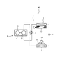
以下、第1実施形態について図1から図5を参照しながら説明する。図2において、ヒートポンプ式冷凍サイクル装置1を構成する圧縮機2は、圧縮部3とモータ4を同一の鉄製密閉容器5内に収容して構成され、モータ4のロータシャフトが圧縮部3に連結されている。そして、圧縮機2、四方弁6、室内熱交換器7、減圧装置8、室外熱交換器9は、熱伝達媒体流路たるパイプにより閉ループを構成するように接続されている。尚、圧縮機2は、例えばロータリ型の圧縮機であり、モータ4は、例えば3相IPM(Interior Permanent Magnet)モータ,ブラシレスDCモータである。空気調和機Eは、上記のヒートポンプ式冷凍サイクル装置1を有している。
以下、第1実施形態について図1から図5を参照しながら説明する。図2において、ヒートポンプ式冷凍サイクル装置1を構成する圧縮機2は、圧縮部3とモータ4を同一の鉄製密閉容器5内に収容して構成され、モータ4のロータシャフトが圧縮部3に連結されている。そして、圧縮機2、四方弁6、室内熱交換器7、減圧装置8、室外熱交換器9は、熱伝達媒体流路たるパイプにより閉ループを構成するように接続されている。尚、圧縮機2は、例えばロータリ型の圧縮機であり、モータ4は、例えば3相IPM(Interior Permanent Magnet)モータ,ブラシレスDCモータである。空気調和機Eは、上記のヒートポンプ式冷凍サイクル装置1を有している。
空気調和機Eの暖房運転時には、四方弁6は実線で示す状態にあり、圧縮機2の圧縮部3で圧縮された高温冷媒は、四方弁6から室内熱交換器7に供給されて凝縮し、その後、減圧装置8で減圧され、低温となって室外熱交換器9に流れ、ここで蒸発して圧縮機2へと戻る。一方、冷房運転時には、四方弁6は破線で示す状態に切り替えられる。このため、圧縮機2の圧縮部3で圧縮された高温冷媒は、四方弁6から室外熱交換器9に供給されて凝縮し、その後、減圧装置8で減圧され、低温となって室内熱交換器7に流れ、ここで蒸発して圧縮機2へと戻る。
室外熱交換器9は、暖房運転時には蒸発器として、冷房運転時には凝縮器として機能し、室内熱交換器7は、逆に、暖房運転時には凝縮器として、冷房運転時には蒸発器として機能するようになっている。そして、室内側、室外側の各熱交換器7,9には、それぞれファン10,11により送風が行われ、その送風によって各熱交換器7,9と室内空気、室外空気の熱交換が効率良く行われるように構成されている。室外熱交換器9に送風を行うファン11はプロペラファンであり、ファンモータ12により駆動される。ファンモータ12は、例えばモータ4と同様のブラシレスDCモータである。
図1は、上記ファンモータ12を駆動するモータ制御装置の構成を示す機能ブロック図である。直流電源部21は、直流電源のシンボルで示しているが、商用交流電源から直流電源を生成している場合には、整流回路や平滑コンデンサ等を含んでいる。直流電源部21には、正側母線22a,負側母線22bを介してインバータ回路23が接続されているが、負側母線22b側には電流検出素子であるシャント抵抗24が挿入されている。インバータ回路23は、スイッチング素子として例えばNチャネル型のパワーMOSFET25(U+,V+,W+,U-,V-,W-)を3相ブリッジ接続して構成されており、各相の出力端子はモータ12の各相巻線にそれぞれ接続されている。
電流検出素子であるシャント抵抗24の両端間の端子電圧は電流値に対応した電圧信号であり、電流検出部27により検出される。電流検出部27は、前記端子電圧をA/D変換して読み込むと、その時に駆動回路33からインバータ回路23に出力される3相のPWM信号パターンに基づいてU,V,W各相の電流Iu,Iv,Iwを検出する。電流検出部27が検出した各相電流は、ベクトル演算部30に入力される。
ベクトル演算部30では、制御条件を設定するマイクロコンピュータ等の機能部分よりモータ12の回転速度指令ωrefが与えられると、推定したモータ12の実際の回転速度との差分に基づいてトルク電流指令Iqrefが生成される。ここで、モータ12の回転速度指令ωrefは、空気調和機Eの図示しない制御装置から供給されるデータであり、冷凍サイクルの状態や空気調和機Eの運転状態から当該制御装置において決定される、空気調和機Eとして所望するファンモータ12の回転数である。
モータ12の各相電流Iu,Iv,Iwからはモータ12のロータ位置θが決定され、そのロータ位置θを用いるベクトル制御演算によりトルク電流Iq,励磁電流Idが算出される。トルク電流指令Iqrefとトルク電流Iqとの差分に対して例えばPI制御演算が行われ、電圧指令Vqが生成される。励磁電流Id側についても同様に処理されて電圧指令Vdが生成され、電圧指令Vq,Vdが上記ロータ位置θを用いて三相電圧Vu,Vv,Vwに変換される。三相電圧Vu,Vv,Vwは、DUTY生成部31に入力され、各相のPWM信号を生成するためのデューティU_DUTY,V_DUTY,W_DUTYが決定される。
各相デューティU,V,W_DUTYは、PWM信号生成部32に与えられ、搬送波,キャリアとのレベルが比較されることで2相変調されたPWM信号又は3相変調された信号PWM信号が生成される。以下では、2相変調されたPWM信号を2相PWM信号とも称し、3相変調された信号PWM信号を3相PWM信号とも称する。また、2相又は3相PWM信号を反転させた下アーム側の信号も生成されて、必要に応じてデッドタイムが付加された後、それらが駆動回路33に出力される。検出方式選択部35は、詳細を後述するが、PWM信号生成部32からのPWM割り込み信号を受けて、「切替えフラグ」を信号として電流検出部27,DUTY生成部31及びPWM信号生成部32に出力する。尚、ベクトル演算部30及びDUTY生成部31も、PWM信号生成部に相当する。
駆動回路33は、与えられたPWM信号に従い、インバータ回路23を構成する6つのFET25(U+,V+,W+,U-,V-,W-)の各ゲートに、ゲート信号を出力する。尚、上アーム側については、必要なレベルだけ昇圧した電位で出力する。以上において、駆動回路33を除く構成27~35の機能は、CPUを含むマイクロコンピュータのハードウェア及びソフトウェアにより実現される機能である。
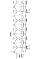
さらに、本実施形態について図3から図5を参照して説明する。本実施形態では図4に示すように、ベクトル演算部30及びDUTY生成部31では、PWMキャリア周期の例えば4周期を1制御単位として扱う。この制御単位を1周期として制御が繰り返し実行されるため、以下ではこれを単に「制御周期」と称する。
尚、圧縮機2を駆動するインバータ回路においては、1回転中に吸込み-圧縮-吐出という負荷変動が生じること,及び運転中に除霜運転等の冷凍サイクルの大きな負荷変動を伴うことからモータの出力トルクの応答性を高める必要があり、さらにキヤリア周波数が低いことから1PWMキャリア周期を1制御周期としてPWM信号を生成する。これに比べて、ファンモータ12を駆動する場合、1回転中に負荷変動がなく、運転中の負荷変動も小さく、且つキャリア周期が短い,すなわち周波数が高いため、複数のPWMキャリア周期を1制御周期として運転することが一般的である。この制御周期内では新たな電流検出やベクトル演算は実行されず、制御周期の開始前に決定されたデューティU_DUTY,V_DUTY,W_DUTYが当該制御周期期間中はそのまま用いられる。すなわち、べクトル演算は制御周期毎に実行され、キャリア周期毎には実行されないようになっている。
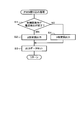
図3は、前記キャリア周期毎に発生するPWM割込み処理の内容を示すフローチャートである。先ず、次の制御周期おいて出力する予定の2相変調でのPWM信号により制御周期内での電流検出が完了できるか否かを判断し(S1)、完了できないと判定されれば(NO)3相変調を実行するように各相デューティパルスを設定する(S4)。この時、検出方式選択部35は、図1に示す「切替えフラグ」をセットする。この「切替フラグ」に基づいて、DUTY生成部31及びPWM信号生成部32は、3相変調に対応したPWM信号パターンの出力データをセットして(S3)、インバータ回路23のスイッチングを行う。
3相変調を実行する際には、図4に示すように、特許文献1と同様に、確実に電流が検出でき、且つ、PWMキャリア周期における供給電圧が本来の指示値と一致するように各相デューティパルスのシフトを行う。さらに、PWMキャリア周期の中間位相であるキャリア波形のボトムを基準とする前後の固定タイミングで、PWM信号生成部32から電流検出部27に対して電流検出タイミング信号が出力される。このタイミングにおいて電流検出部27が2相の電流を検出する。例えば、図4に示す最も左側のキャリア周期である第1キャリア周期では、V,U相の電流が検出される。V,U相の電流が検出できれば、演算によってW相の電流が算出でき、三相分のモータ電流が検出できる。
上記のように第1周期で電流検出が完了すると、次回,つまり第2キャリア周期以降の割り込み処理ではステップS1で「YES」と判断し、2相変調出力を選択して(S2)ステップS3を実行する。2相変調出力を選択する際には「切替えフラグ」をリセットする。2相変調出力は、例えば3相変調出力においてデューティが最小となる相のデューティをゼロとして、その他の2相のデューティより上記最小値を減じることで設定する。以後の制御周期内のキヤリア周期,すなわち第3,第4キャリア周期は、何れもこのような処理の流れになり、第2周期と同じ波形の2相変調された2相PWM信号が出力される。
その結果、図4に示すように、制御周期中の第1キャリア周期では3相変調が実行され、第2~第4キャリア周期では2相変調が実行される。尚、第1キャリア周期において2回目の電流検出を行った時点で、図1に示すように電流検出部27がベクトル演算部30に電流検出完了割込みを発生させて、それをベクトル演算部30がベクトル制御演算を開始させるトリガとしても良い。
2相変調の場合、各PWMキャリア周期において何れか1相は上側スイッチング素子がオフに固定されるため、全てのスイッチング素子をオン,オフする3相変調に比較して、インバータ回路23におけるスイッチング素子のオン,オフ回数を減少させることができる。従来は、電流が検出できないような状態では、その制御周期中の全てのPWMキャリア周期で3相変調を行っていた。これに対して本実施形態では、制御周期中の1つのPWMキヤリア周期においてのみ電流検出用の3相変調を行い、他のPWMキヤリア周期では2相変調信号を出力することで、効率の向上を図ることができる。
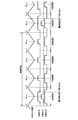
図5は、本実施形態の変調方式切替え制御を適用した場合の各回転数に対する消費電力の低減量の一例を示す。比較の対象としたのは、従来考えられていた、2相変調のPWM波形では電流読み取りができない場合に、その制御周期中の全てのPWMキヤリア周期で3相変調を行う方式である。図5は、その方式を基準とした改善効果を示している。本実施形態によれば、少なくとも1制御周期中のPWMキャリア周期4周期中の3周期は必ず2相変調となることから、効率の良い2相変調による運転割合が高くなった結果、ほぼ回転数の全域で消費電力の低減効果があることが分かる。同図からは、概ね200rpm以上では、消費電力が0.5W~1.6W程度低減されていることが分かる。尚、図5は、モータ12として、定格電力が70Wのファン駆動用モータを適用した試験結果である。
以上のように本実施形態によれば、電流検出部27は、インバータ回路23の直流側に接続されるシャント抵抗24が電流値に対応して発生した信号とPWM信号パターンとに基づいてモータ4の相電流Iu,Iv,Iwを検出し、ベクトル演算部30は相電流に基づいてロータ位置θを決定し、PWM信号生成部32と共に、ロータ位置θに追従するように2相又は3相のPWM信号パターンを生成する。このとき、PWM信号生成部32は、3相のPWM信号パターンの何れか1相は、キャリア周期のボトムを基準として遅れ側,進み側の双方向にデューティを増減させ、他の1相は前記ボトムを基準として遅れ側,進み側の一方向に、残りの1相は前記方向とは逆方向にデューティを増減させる。
これにより、電流検出部27が、PWMキャリア周期内で固定された2点のタイミングで2相の電流を検出可能となる3相変調のPWM信号パターンを生成する。そして、検出方式選択部35は、PWMキャリア周期の4周期を1制御周期とし、その制御周期内においてDUTY生成部31及びPWM信号生成部32に、3相のPWM信号パターンと2相のPWM信号パターンとが混在するように生成させるようにした。
具体的には、制御周期内の第1キャリア周期で3相変調を行い、第2~第4キャリア周期で2相変調を行うようにした。これにより、3相変調の実行時に2相の電流を確実に検出し、その他は2相変調を行うことでスイッチング損失をより低減できる。尚、1制御周期内で1回の電流検出ができれば、次回の制御周期におけるデューティが決定できるので、制御周期内の最後のキャリア周期又は途中の1キャリア周期において、電流検出可能な3相変調のPWM信号を出力しても良い。
また、本実施形態のモータ制御装置を、圧縮機2と、室外熱交換器9と、減圧装置8と、室内熱交換器7とを備えるヒートポンプ式冷凍サイクル装置1を備える空気調和機Eに適用し、ファンモータ12を制御対象とするので、ヒートポンプ式冷凍サイクル装置1及び空気調和機Eの運転効率を向上させることができる。
(第2実施形態)
以下、第1実施形態と同一部分には同一符号を付して説明を省略し、異なる部分について説明する。図6に示すように、第2実施形態では、図示しないが、インバータ回路23の下側アームであるFET25U-,25V-,25W-の各ソースにシャント抵抗を挿入する3シャント方式で各相電流を検出する構成に適用する。この場合、特許文献1のように固定した2点の検出タイミングで電流を検出する必要はなく、各相の下側アームのFET25がオンしている期間に各相電流が検出できる。
以下、第1実施形態と同一部分には同一符号を付して説明を省略し、異なる部分について説明する。図6に示すように、第2実施形態では、図示しないが、インバータ回路23の下側アームであるFET25U-,25V-,25W-の各ソースにシャント抵抗を挿入する3シャント方式で各相電流を検出する構成に適用する。この場合、特許文献1のように固定した2点の検出タイミングで電流を検出する必要はなく、各相の下側アームのFET25がオンしている期間に各相電流が検出できる。
(その他の実施形態)
PWM信号生成部32が3相PWM信号を生成する方式については、例えば特許文献1に開示されている、同特許文献中の第4実施形態の方式を用いても良く、PWM信号生成部32は、所定のタイミングで2相の電流を検出可能となる3相のPWM信号パターンを生成できれば良い。
制御単位周期は、必ずしもPWMキャリアの4周期に設定する必要はなく、2周期以上であれば電力低減効果が得られる。
また、制御単位周期中において3相変調を実行する回数は2回以上でも良いが、3相変調の実行回数は2相変調の実行回数よりも少なく設定する方が、スイッチング損失を低減する観点からは望ましい。
PWM信号生成部32が3相PWM信号を生成する方式については、例えば特許文献1に開示されている、同特許文献中の第4実施形態の方式を用いても良く、PWM信号生成部32は、所定のタイミングで2相の電流を検出可能となる3相のPWM信号パターンを生成できれば良い。
制御単位周期は、必ずしもPWMキャリアの4周期に設定する必要はなく、2周期以上であれば電力低減効果が得られる。
また、制御単位周期中において3相変調を実行する回数は2回以上でも良いが、3相変調の実行回数は2相変調の実行回数よりも少なく設定する方が、スイッチング損失を低減する観点からは望ましい。
特許文献1のように、低速領域では3相変調のみを実行し、高速領域では2相変調のみを実行するように切替える構成において、低速領域での制御に第1実施形態を適用しても良い。
モータ制御装置の適用対象は、空気調和機やヒートポンプ式冷凍サイクル装置に限らない。また、駆動対象もファンモータに限ることはなく、複数のキャリア周期を1制御周期としてPWM駆動するモータ制御装置であれば適用可能である。
モータ制御装置の適用対象は、空気調和機やヒートポンプ式冷凍サイクル装置に限らない。また、駆動対象もファンモータに限ることはなく、複数のキャリア周期を1制御周期としてPWM駆動するモータ制御装置であれば適用可能である。
本発明のいくつかの実施形態を説明したが、これらの実施形態は例として提示したものであり、発明の範囲を限定することは意図していない。これら新規な実施形態は、その他の様々な形態で実施されることが可能であり、発明の要旨を逸脱しない範囲で種々の省略、置き換え、変更を行うことができる。これらの実施形態やその変形は、発明の範囲や要旨に含まれると共に、特許請求の範囲に記載された発明とその均等の範囲に含まれる。
以上のように、実施形態にかかるモータ制御装置は、3相モータをPWM制御するものに有用である。
Claims (6)
- 3相ブリッジ接続された複数のスイッチング素子を所定のPWM信号パターンに従いオンオフ制御することで、直流を3相交流に変換するインバータ回路を介してモータを駆動するモータ制御装置において、
前記モータの相電流を検出する電流検出部と、
前記モータの相電流に基づいてロータ位置を決定するロータ位置決定部と、
前記ロータ位置に追従するように2相又は3相のPWM信号パターンを生成するPWM信号生成部とを備え、
前記PWM信号生成部は、複数のPWM制御周期を1制御単位として、前記制御単位内に3相のPWM信号パターンと2相のPWM信号パターンとが混在するように生成するモータ制御装置。 - 前記PWM信号生成部は、3以上のPWM制御周期を1制御単位とする際に、3相のPWM信号パターンの生成割合を、2相のPWM信号パターンの生成割合よりも少なくする請求項1記載のモータ制御装置。
- 前記電流検出部は、前記インバータ回路の直流側に接続され、電流値に対応する信号を発生する電流検出素子を備え、前記電流検出素子に発生した信号と前記PWM信号パターンとに基づいて前記モータの相電流を検出し、
前記PWM信号生成部は、前記3相のPWM信号パターンとして、所定のタイミングで2相の電流を検出可能となるPWM信号パターンを生成する請求項1又は2記載のモータ制御装置。 - 前記PWM信号生成部は、前記3相のPWM信号パターンのうち何れか1相については、前記搬送波周期の任意の位相を基準として遅れ側,進み側の双方向にデューティを増減させ、
他の1相については、前記搬送波周期の任意の位相を基準として遅れ側,進み側の一方向にデューティを増減させ、
残りの1相については、前記搬送波周期の任意の位相を基準として前記方向とは逆方向にデューティを増減させることで、前記電流検出部が、前記PWM信号の搬送波周期内で固定された2点のタイミングで2相の電流を検出可能となるように3相のPWM信号パターンを生成する請求項3記載のモータ制御装置。 - 前記モータが、送風を行うファンを駆動するものに適用される請求項1から4の何れか一項に記載のモータ制御装置。
- ファンを駆動するファンモータと、
請求項5記載のモータ制御装置とを備えるヒートポンプ式冷凍サイクル装置。
Applications Claiming Priority (2)
| Application Number | Priority Date | Filing Date | Title |
|---|---|---|---|
| JP2016-185513 | 2016-09-23 | ||
| JP2016185513A JP2019205214A (ja) | 2016-09-23 | 2016-09-23 | モータ制御装置及びヒートポンプ式冷凍サイクル装置 |
Publications (1)
| Publication Number | Publication Date |
|---|---|
| WO2018055820A1 true WO2018055820A1 (ja) | 2018-03-29 |
Family
ID=61690265
Family Applications (1)
| Application Number | Title | Priority Date | Filing Date |
|---|---|---|---|
| PCT/JP2017/015315 Ceased WO2018055820A1 (ja) | 2016-09-23 | 2017-04-14 | モータ制御装置及びヒートポンプ式冷凍サイクル装置 |
Country Status (2)
| Country | Link |
|---|---|
| JP (1) | JP2019205214A (ja) |
| WO (1) | WO2018055820A1 (ja) |
Families Citing this family (1)
| Publication number | Priority date | Publication date | Assignee | Title |
|---|---|---|---|---|
| JP7034368B1 (ja) | 2021-12-06 | 2022-03-11 | 日立ジョンソンコントロールズ空調株式会社 | モータの駆動制御装置、駆動制御方法および冷凍空調機 |
Citations (2)
| Publication number | Priority date | Publication date | Assignee | Title |
|---|---|---|---|---|
| JP2013208009A (ja) * | 2012-03-29 | 2013-10-07 | Brother Ind Ltd | モータ制御装置 |
| JP2014171321A (ja) * | 2013-03-04 | 2014-09-18 | Toshiba Corp | モータ制御装置,ヒートポンプシステム及び空気調和機 |
-
2016
- 2016-09-23 JP JP2016185513A patent/JP2019205214A/ja active Pending
-
2017
- 2017-04-14 WO PCT/JP2017/015315 patent/WO2018055820A1/ja not_active Ceased
Patent Citations (2)
| Publication number | Priority date | Publication date | Assignee | Title |
|---|---|---|---|---|
| JP2013208009A (ja) * | 2012-03-29 | 2013-10-07 | Brother Ind Ltd | モータ制御装置 |
| JP2014171321A (ja) * | 2013-03-04 | 2014-09-18 | Toshiba Corp | モータ制御装置,ヒートポンプシステム及び空気調和機 |
Also Published As
| Publication number | Publication date |
|---|---|
| JP2019205214A (ja) | 2019-11-28 |
Similar Documents
| Publication | Publication Date | Title |
|---|---|---|
| JP6296930B2 (ja) | モータ制御装置及び空気調和機 | |
| JP6165470B2 (ja) | モータ制御装置,ヒートポンプシステム及び空気調和機 | |
| US10637377B2 (en) | Motor driving device, as well as refrigerator and device for operating compressor in which said motor driving device is used | |
| JP4053968B2 (ja) | 同期電動機駆動装置及び冷凍冷蔵庫及び空気調和機 | |
| JP3971979B2 (ja) | 空気調和装置 | |
| JP6718356B2 (ja) | モータ制御装置及びヒートポンプ式冷凍サイクル装置 | |
| JP3644391B2 (ja) | インバータ装置、圧縮機制御装置、冷凍・空調装置の制御装置、モータの制御方法、圧縮機、冷凍・空調装置 | |
| JP6246756B2 (ja) | モータ制御装置,ヒートポンプシステム及び空気調和機 | |
| JP7074613B2 (ja) | オープン巻線モータ駆動装置及び冷凍サイクル装置 | |
| JP6533950B2 (ja) | モータ駆動装置、およびこれを用いた圧縮機の駆動装置、冷凍装置および冷蔵庫 | |
| JP7341359B2 (ja) | 電力変換装置、モータ駆動装置及び冷凍サイクル適用機器 | |
| JP2019165573A (ja) | 冷凍サイクル装置 | |
| JP4744505B2 (ja) | モータ駆動制御装置、モータ駆動制御方法及び座標変換方法、並びに換気扇、液体用ポンプ、送風機、冷媒圧縮機、空気調和機及び冷蔵庫 | |
| JP2018042336A (ja) | 同期電動機の回転位置装置,空調機及び洗濯機 | |
| US20230045429A1 (en) | Motor control device and air conditioner | |
| JP6982532B2 (ja) | 冷凍サイクル装置 | |
| CN101001075B (zh) | 一种直流变频压缩机转矩控制装置和方法 | |
| JP5975830B2 (ja) | モータ制御装置、およびそれを用いた冷凍機器 | |
| JP4804100B2 (ja) | モータ駆動装置及びその制御方法、空気調和装置 | |
| WO2018055820A1 (ja) | モータ制御装置及びヒートポンプ式冷凍サイクル装置 | |
| JP7237746B2 (ja) | オープン巻線モータ駆動装置及び冷凍サイクル装置 | |
| JP2003037988A (ja) | ブラシレスdcモータの駆動方法及び装置 | |
| WO2023095311A1 (ja) | 電力変換装置、電動機駆動装置及び冷凍サイクル適用機器 | |
| JP2006136167A (ja) | 電力変換装置、電力変換装置の制御方法及び空気調和装置 | |
| KR20140145231A (ko) | 냉장고 및 그 제어방법 |
Legal Events
| Date | Code | Title | Description |
|---|---|---|---|
| 121 | Ep: the epo has been informed by wipo that ep was designated in this application |
Ref document number: 17852601 Country of ref document: EP Kind code of ref document: A1 |
|
| NENP | Non-entry into the national phase |
Ref country code: DE |
|
| 122 | Ep: pct application non-entry in european phase |
Ref document number: 17852601 Country of ref document: EP Kind code of ref document: A1 |
|
| NENP | Non-entry into the national phase |
Ref country code: JP |