WO2018055816A1 - レール機構 - Google Patents
レール機構 Download PDFInfo
- Publication number
- WO2018055816A1 WO2018055816A1 PCT/JP2017/013797 JP2017013797W WO2018055816A1 WO 2018055816 A1 WO2018055816 A1 WO 2018055816A1 JP 2017013797 W JP2017013797 W JP 2017013797W WO 2018055816 A1 WO2018055816 A1 WO 2018055816A1
- Authority
- WO
- WIPO (PCT)
- Prior art keywords
- cover
- rail
- lower rail
- width direction
- side wall
- Prior art date
- Legal status (The legal status is an assumption and is not a legal conclusion. Google has not performed a legal analysis and makes no representation as to the accuracy of the status listed.)
- Ceased
Links
Images








Classifications
-
- B—PERFORMING OPERATIONS; TRANSPORTING
- B60—VEHICLES IN GENERAL
- B60N—SEATS SPECIALLY ADAPTED FOR VEHICLES; VEHICLE PASSENGER ACCOMMODATION NOT OTHERWISE PROVIDED FOR
- B60N2/00—Seats specially adapted for vehicles; Arrangement or mounting of seats in vehicles
- B60N2/02—Seats specially adapted for vehicles; Arrangement or mounting of seats in vehicles the seat or part thereof being movable, e.g. adjustable
- B60N2/04—Seats specially adapted for vehicles; Arrangement or mounting of seats in vehicles the seat or part thereof being movable, e.g. adjustable the whole seat being movable
- B60N2/06—Seats specially adapted for vehicles; Arrangement or mounting of seats in vehicles the seat or part thereof being movable, e.g. adjustable the whole seat being movable slidable
-
- B—PERFORMING OPERATIONS; TRANSPORTING
- B60—VEHICLES IN GENERAL
- B60N—SEATS SPECIALLY ADAPTED FOR VEHICLES; VEHICLE PASSENGER ACCOMMODATION NOT OTHERWISE PROVIDED FOR
- B60N2/00—Seats specially adapted for vehicles; Arrangement or mounting of seats in vehicles
- B60N2/02—Seats specially adapted for vehicles; Arrangement or mounting of seats in vehicles the seat or part thereof being movable, e.g. adjustable
- B60N2/04—Seats specially adapted for vehicles; Arrangement or mounting of seats in vehicles the seat or part thereof being movable, e.g. adjustable the whole seat being movable
- B60N2/06—Seats specially adapted for vehicles; Arrangement or mounting of seats in vehicles the seat or part thereof being movable, e.g. adjustable the whole seat being movable slidable
- B60N2/07—Slide construction
Definitions
- This invention relates to the rail mechanism arrange
- a rail cover for example, Patent Document 1
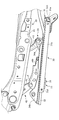
- the rail mechanism described in Patent Document 1 (“Slide Rail 110” in Patent Document 1) will be described with reference to FIG. 18.
- the rail cover 160 (“Cover Member” in Patent Document 1) provided on the slide rail 110 is as follows. , And upper extending portions 172 and 174 erected on the outer sides of the side walls 212 and 214 of the lower rail 122.
- Claw portions 202 and 204 (“fixing members” in Patent Document 1) that are engaged with the side walls 212 and 214 of the lower rail 122 are formed in the upper extending portions 172 and 174. With the above configuration, the rail cover 160 is directly fixed to the side wall 212 of the lower rail 122.
- the claw portions 202 and 204 wrap around the side walls 212 and 214 of the lower rail 122 and engage with the side walls 212 and 214 as shown in FIG.
- the upper rail 120 disposed between the side walls 212 and 214 of the lower rail 122 may interfere with the claw portions 202 and 204 when moving in the space between the side walls 212 and 214.
- the mounting position of the rail cover on the lower rail is set not at the side wall of the lower rail but at the lower position of the lower rail.
- the rail cover is assembled to the lower rail outside the lower rail.
- a part for attaching the rail cover is set on the lower surface of the lower rail, and the part is extended outward from the side wall of the lower rail. It is conceivable to engage a predetermined portion of the rail cover with the protruding portion.
- the rail cover mounting part extends to the outside of the side wall of the lower rail, the size of the above part increases, resulting in an increase in the size of the entire rail mechanism. Become.
- the present invention has been made in view of the above-described problems, and an object thereof is to provide a rail mechanism capable of assembling a rail cover to a lower rail with a more compact configuration.
- the subject is a rail mechanism arranged at the lower part of a vehicle seat, the lower rail, a rail cover that covers an end of the lower rail in the extending direction of the lower rail,
- a convex portion provided to fix the lower rail and projecting downward from the lower surface of the lower rail, and the convex portion includes a facing portion facing the rail cover, and the facing portion is It is located between both ends of the lower rail in the width direction of the vehicle seat, and is solved by restricting the rail cover from moving in at least one of the extending direction and the width direction.
- the convex portion that protrudes downward from the lower surface of the lower rail has a portion facing the rail cover.
- the rail cover movement restriction in at least one of the extending direction of the lower rail and the width direction of the vehicle seat is performed.
- said opposing part is located between the both ends of a lower rail in a sheet
- the rail cover has a first cover assembled to the lower rail, and a second cover assembled to the lower rail outside the first cover in the width direction,
- the first cover forms an engaging portion at an end portion of the first cover in the width direction
- the second cover has an engaged portion that engages with the engaging portion. It is good to be assembled
- the engaged portion provided on the second cover is engaged with the engaging portion formed on the first cover, so that the movement of the second cover in the sheet width direction is restricted. As a result, the second cover can be appropriately assembled to the lower rail.
- a side wall is provided at an end of the lower rail in the width direction, and the engaging portion is formed between the end of the first cover and the side wall in the width direction.
- the second cover is restricted in movement in the width direction by the end portion of the first cover and the side wall in the width direction when the engaged portion is engaged with the engagement portion. It is good to have assembled
- the clearance gap formed between the edge part of a 1st cover and the side wall of a lower rail functions as an engaging part.
- the engaging portion of the second cover is sandwiched between the end portion of the first cover and the side wall of the lower rail so that the movement of the second cover in the seat width direction is more appropriately regulated.
- the rail cover has a first cover assembled to the lower rail, and a second cover assembled to the lower rail outside the first cover in the width direction,
- a side wall is provided at an end of the lower rail in the width direction, and a fixing portion is provided in a portion of the side wall that faces the second cover in the width direction.
- a portion to be opposed to the side wall is provided with a fixed portion that engages with the fixed portion, and the fixed portion is engaged with the fixed portion so that movement in the extending direction is restricted to the lower rail. It should be fixed.
- the movement of the 2nd cover in the front-back direction is controlled because the to-be-fixed part provided in the 2nd cover is engaged with the fixing
- the second cover can be appropriately assembled to the lower rail.
- the fixing portion may be arranged at a position where at least a part of the fixing portion is within a range in which the facing portion is provided in the extending direction.
- at least a part of the fixed portion is in the range where the facing portion exists in the extending direction of the lower rail.
- the first cover forms an engaging portion at an end portion of the first cover in the width direction
- the second cover engages with the engaging portion.
- the engaged portion is assembled to the lower rail in a state in which movement in the width direction is restricted by engaging the engaged portion with the engaging portion. It is good to arrange
- at least a part of the engaged portion is within the range where the fixed portion of the second cover exists in the height direction of the lower rail. As a result, it is possible to suppress the second cover from being enlarged with the provision of the above-described engaged portion.
- a fastener that penetrates both the lower rail and the convex portion and fixes the both, and the fixing portion is provided with the fastener in the extending direction. It is good to arrange
- at least a part of the fixing portion of the lower rail is in the range where the fastener exists in the extending direction of the lower rail.
- the position of the fixing part with respect to the fastener is set to a suitable position for suppressing the enlargement of the lower rail accompanying the provision of the fixing part.
- a side wall is provided at an end of the lower rail in the width direction, and an engagement hole is formed in the side wall, and the rail cover is used to fasten the rail cover to the side wall.
- a claw portion that can be engaged with the engagement hole, and a notch that is formed so as to reach a position where the claw portion is provided in the extending direction.
- the rail cover is notched. This notch is formed so as to reach a position where a claw portion for fastening the rail cover to the side wall of the lower rail is provided in the extending direction of the lower rail.
- the rail cover can be assembled to the lower rail with a more compact configuration.
- a 2nd cover comes to be assembled
- a 2nd cover comes to be assembled
- fixed part with respect to an opposing part is set to the position which can suppress that a lower rail enlarges with providing the said fixing
- the position of the to-be-engaged part with respect to a to-be-fixed part is set to the position which can suppress that a 2nd cover enlarges by providing the said to-be-engaged part. Is done.
- fixed part with respect to a fastener is set to a suitable position, when it suppresses that a lower rail enlarges with providing the said fixing
- in the rail cover the vicinity of the claw portion that can be engaged with the engagement hole of the lower rail is easily bent, and the claw portion is easily engaged with the engagement hole.
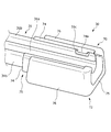
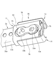
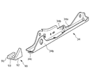
- FIG. 1 It is a perspective view which shows the flame
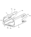
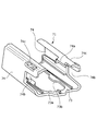
- FIG. 3 is a part view of the first cover (part 1). It is a component drawing of a 1st cover (the 2). It is component drawing of a 2nd cover. It is a figure which shows the 1st cover of the state assembled
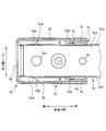
- FIG. 5 is a view showing an AA cross section in FIG. 4.
- FIG. 8 is a diagram showing a BB cross section in FIG. 7. It is a perspective view which shows the edge part of the rail mechanism which concerns on a modification. It is a figure which shows CC cross section in FIG. It is a figure which shows the structure of the rail mechanism which concerns on a prior art example.
- a vehicle seat is taken as an example of a vehicle seat, and a slide rail mechanism as a rail mechanism provided on the vehicle seat will be described.
- the rail mechanism of this invention is not limited to what was provided in the vehicle seat, It can utilize also for the other vehicle seat (for example, seat seat mounted in a ship or an aircraft).
- the “front-rear direction” means the front-rear direction of the vehicle seat, and is the front-rear direction when viewed from the seated person of the vehicle seat, that is, the direction that coincides with the traveling direction of the vehicle.
- the “seat width direction” means the width direction of the vehicle seat, and coincides with the left-right direction when viewed from the seated person of the vehicle seat.
- the “height direction” means the height direction of the vehicle seat and coincides with the height direction of the lower rail 31 described later.
- each member described below represent the position and state in the vehicle seat as a finished product unless otherwise specified.
- FIGS. 1 and 2 referred to in a later section the rail cover 70 is omitted for convenience of illustration.
- 14 and 15 referred to in the later section are cross-sectional views, but for the purpose of explaining the positional relationship of each part of the rail cover 70, a portion that does not originally appear in the cross-section (specifically, The first protrusion 76a in FIG. 14 and the rail positioning member 33) in FIG. 15 are indicated by broken lines.
- the basic configuration of the vehicle seat according to the present embodiment is substantially the same as a known general vehicle seat, and includes a seat back, a seat cushion, and a headrest. Further, the vehicle seat S has a seat frame F shown in FIG. 1 as its skeleton.
- the seat frame F includes a seat back frame 10 and a seat cushion frame 20 as main components.
- a slide rail mechanism 30 for slidably moving the seat back, the seat cushion, and the headrest in the front-rear direction is disposed below the vehicle seat.
- the slide rail mechanism 30 is provided as a pair on the left and right sides with a gap therebetween.
- each slide rail mechanism 30 includes a lower rail 31 that is fixed to the vehicle body in a state of extending in the front-rear direction, and an upper rail 32 that is movable along the extending direction of the lower rail 31.
- the slide rail mechanism 30 has a link support bracket 34.
- the link support bracket 34 is a metal plate member that supports the rotation links 41 and 42 that constitute the height adjustment mechanism 40 for adjusting the height of the seat cushion. More specifically, the rotation links 41 and 42 of the height adjusting mechanism 40 are supported by the front end portion and the rear end portion of the link support bracket 34 via a pivot pin P so as to be swingable.
- the pivot links 41 and 42 swing (rotate) around the pivot pin P
- the seat cushion frame 20 moves up and down in conjunction with this. That is, each of the rotation links 41 and 42 rotates around the rotation axis along the seat width direction so as to rotate the seat cushion. Thereby, the position (height) of the seat cushion is adjusted in the height direction.
- the slide rail mechanism 30 includes the lower rail 31, the upper rail 32, and the link support bracket 34 as described above.
- a rail positioning member 33 is attached to the lower surface of the lower rail 31.
- a rail cover 70 is assembled to the lower rail 31.
- the rail cover 70 is a member that covers an end (edge) of the lower rail 31 in the extending direction of the lower rail 31. Note that when the vehicle seat according to the present embodiment is installed in front of the vehicle (in a simple manner, the seat of the driver seat or the passenger seat), the rail cover 70 is provided with a lower rail as shown in FIGS. It is used for the purpose of covering the rear end of 31.
- the lower rail 31 has a bottom wall 31a and side walls 31b provided upright at both end portions of the bottom wall 31a.
- Each side wall 31b is provided at an end of the lower rail 31 in the seat width direction. Further, the upper end portion of each side wall 31b is folded back in an inverted U shape.
- a substantially rectangular engagement hole 31c is formed at the upper end of each side wall 31b.
- the engagement hole 31c is provided slightly forward from the rear end of the side wall 31b in the front-rear direction.
- the engagement hole 31c is a portion of the upper end portion of the side wall 31b that is folded in an inverted U shape that hangs from the portion positioned at the uppermost position to the portion hanging down on the inner side in the sheet width direction. It is formed by cutting up.
- the rail cover 70 is assembled
- a recess 31d is formed at the rear end of each side wall 31b.
- the recess 31d is a rectangular through-hole provided in the center portion of the side wall 31b in the height direction, and is located slightly forward from the rear end of the side wall 31b in the front-rear direction.
- the recessed part 31d functions as a fixing
- the part in which the recessed part 31d is formed among the side walls 31b corresponds to the part facing the inner surface of the 2nd cover side part 76 mentioned later.
- the upper rail 32 has substantially the same configuration as a general upper rail, and can slide in the front-rear direction while being disposed between the side walls 31b of the lower rail 31.
- a link support bracket 34 is fixed to the upper surface of the upper rail 32 by welding.
- the rail positioning member 33 is a member used for positioning the lower rail 31 with respect to the vehicle body floor and fixing the lower rail 31 at the determined position. As shown in FIGS. 5 and 6, the rail positioning member 33 has an elliptical shape with a depressed central portion in plan view, and is fixed to the lower surface of the bottom wall 31 a of the lower rail 31 by welding. That is, the rail positioning member 33 corresponds to a convex portion that protrudes downward from the lower surface of the lower rail 31.
- a circular through hole (hereinafter referred to as a front through hole) is provided at the front end of the rail positioning member 33.
- the front through hole communicates with a first hole 31 e provided in the bottom wall 31 a of the lower rail 31.
- the positioning pins 35 shown in FIGS. 4 to 7 are inserted into both the front through hole and the first hole 31e that communicate with each other.
- the positioning pin 35 is a component provided for positioning the lower rail 31 via the rail positioning member 33, and its tip end partly protrudes from the lower surface of the rail positioning member 33 through the rail positioning member 33. Yes.
- the lower rail 31 is positioned with respect to a vehicle body floor by fitting the front-end
- a long hole-like through hole (hereinafter referred to as a rear through hole 33a) is provided at the rear end of the rail positioning member 33.
- the rear side through hole 33 a communicates with a second hole 31 f provided in the bottom wall 31 a of the lower rail 31.
- a bolt B as a fastener is inserted into both the rear through hole 33a and the second hole 31f that communicate with each other. The bolt B penetrates the lower rail 31 and the rail positioning member 33, and fixes the lower rail 31 and the rail positioning member 33 to the vehicle body floor.
- the front end of the bolt B passes through the rail positioning member 33 and somewhat from the lower surface of the rail positioning member 33. Jump out. And the lower rail 31 and the rail positioning member 33 are fixed (bolt-fixed) with respect to a vehicle body floor because the front-end
- the rail positioning member 33 is a separate part from the lower rail 31, but is not limited to this.
- a portion corresponding to the rail positioning member 33 may be formed as a part of the lower rail 31 (that is, the portion corresponding to the rail positioning member 33 and the main body portion of the lower rail 31 are configured by one component). .
- the link support bracket 34 extends long in the front-rear direction and is welded to the upper surface of the upper rail 32. As shown in FIG. 8, each link support bracket 34 has a bottom wall 34a and a pair of left and right standing walls 34b erected on the side end of the bottom wall 34a.
- the bottom wall 34 a is a portion that is welded and fixed to the upper surface of the upper rail 32.
- the standing wall 34b positioned on the inner side in the seat width direction supports the rotation links 41 and 42 at the front end portion and the rear end portion.
- the bracket protective cover 90 illustrated in FIG. 8 is attached to the rear end portion of the link support bracket 34.
- the bracket protection cover 90 covers the rear end portion of the link support bracket 34 and is formed of a resin molded product.
- the configuration of the bracket protective cover 90 will be described with reference to FIGS. 8 and 9.
- the bracket protective cover 90 includes a first protective part 91, a second protective part 92, and a connecting part 93.
- the first protection portion 91 is a portion that covers one of the pair of left and right standing walls 34b provided on the link support bracket 34 (specifically, the standing wall 34b on the inner side in the seat width direction) so as to wrap from above and from the side. There is a substantially rectangular shape in side view.
- the second protection portion 92 is a portion that covers the other standing wall 34b (specifically, the standing wall 34b on the outer side in the seat width direction) so as to wrap from above and from the side, and has a substantially triangular shape when viewed from the side. Yes.
- the connecting portion 93 is a portion provided between the first protective portion 91 and the second protective portion 92 in the sheet width direction, and connects the first protective portion 91 and the second protective portion 92.
- the connecting portion 93 is placed on the upper surface of the bottom wall 34 a of the link support bracket 34 when the bracket protection cover 90 is attached to the link support bracket 34.
- a projection 93 a protruding downward is formed on the lower surface (bottom surface) of the connecting portion 93.
- the protrusion 93 a is a portion that engages with a cover attachment hole 34 c provided at the rear end of the bottom wall 34 a of the link support bracket 34. Then, with the first protective portion 91 and the second protective portion 92 covering the corresponding standing wall 34b, the projection 93a engages with the cover mounting hole 34c, so that the bracket protective cover 90 is attached to the link support bracket 34. Covers the rear end.
- the rail cover 70 covers the rear end portion of the lower rail 31, and more specifically, covers the rear end portion of the lower rail 31 from the side, the lower side, and the rear side of the lower rail 31, as shown in FIGS.
- the rail cover 70 according to the present embodiment is composed of two parts. More specifically, the rail cover 70 includes a first cover 71 illustrated in FIGS. 10 and 11 and a second cover 72 illustrated in FIG. It is configured. Hereinafter, each of the first cover 71 and the second cover 72 will be described in detail.
- the first cover 71 is a part of the rail cover 70, and is assembled to the lower rail 31 so as to cover the side and lower side of the lower rail 31, as shown in FIG.
- the first cover 71 is formed of a resin material so as to have the outer shape shown in FIGS. 10 and 11. More specifically, the first cover 71 has a substantially cylindrical shape with an open top, and includes a bottom (hereinafter referred to as a first cover bottom 73) and a pair of left and right side portions (hereinafter referred to as a first cover). Side part 74).
- an elliptical through hole 73 a having a depressed central portion is formed in the central portion of the first cover bottom portion 73.
- the shape of the through-hole 73 a is a shape simulating the outer edge of the rail positioning member 33, and is a size that is slightly larger than the outer edge of the rail positioning member 33.
- the rail positioning member 33 is positioned inside the through hole 73a as shown in FIGS.
- the first cover 71 is assembled to the lower rail 31 with the outer edge portion of the through hole 73 a facing the outer edge portion of the rail positioning member 33 and surrounding the rail positioning member 33. That is, the outer edge portion of the rail positioning member 33 corresponds to a portion 33b facing the rail cover 70 (strictly, the first cover 71).
- the first cover 71 is assembled to the lower rail 31 in a state where the outer edge portion of the through hole 73a surrounds the entire circumference of the facing portion 33b.
- the rail cover 70 (strictly, the first cover 71) is restricted from moving in at least one of the front-rear direction and the seat width direction. That is, the facing portion 33b has a function of restricting the rail cover 70 from moving in at least one of the front-rear direction and the seat width direction.
- the facing portion 33b is located between both ends of the lower rail 31 in the seat width direction. That is, in the present embodiment, the portion where the rail cover 70 (strictly, the first cover 71) is assembled to the lower rail 31 is located between both ends of the lower rail 31 in the seat width direction. As a result, a more compact configuration is realized as a configuration for assembling the rail cover 70 to the lower rail 31.
- the first cover side portion 74 is erected on both side end portions of the first cover bottom portion 73 and constitutes an end portion of the first cover 71 in the sheet width direction.
- the first cover side portion 74 In the state where the first cover 71 is assembled to the lower rail 31, the first cover side portion 74 is located outside the side wall 31b of the lower rail 31 in the seat width direction as shown in FIG.
- the first cover side portion 74 is along the side wall 31b of the lower rail 31 with a certain gap M in the seat width direction (that is, , Adjacent to the side wall 31b).
- the upper end portion of the first cover side portion 74 is bent toward the inner side in the sheet width direction.
- a claw portion 74a that protrudes further inward in the sheet width direction is provided in a portion of the upper end portion of the first cover side portion 74 that extends toward the inner side in the sheet width direction.
- the claw portion 74a is a portion provided to fasten the first cover 71 to the side wall 31b of the lower rail 31, and can be engaged with an engagement hole 31c formed in the side wall 31b. Note that the claw portion 74 a is formed at a slightly forward position from the rear end of the first cover 71.
- the first cover 71 is approached from below the lower rail 31, and the rail positioning member 33 is placed in the through hole 73 a formed in the first cover bottom 73. Get in. Thereafter, the first cover side portion 74 is placed along the side wall 31 b of the lower rail 31. Then, a portion of the upper end portion of the first cover side portion 74 extending toward the inner side in the sheet width direction is bent to engage the claw portion 74a with the engagement hole 31c. Thereby, as shown in FIG. 13, the first cover 71 is assembled to the lower rail 31.
- a rectangular cutout 74b is formed in the portion extending upward in the first cover side portion 74 as shown in FIGS. Has been.
- the notch 74b extends from the rear end of the first cover 71 to the position where the claw 74a is provided in the front-rear direction.
- the notch 74b is formed so as to reach the position where the claw portion 74a is provided in the front-rear direction, so that the vicinity of the claw portion 74a of the first cover side portion 74 is easily bent.
- the claw portion 74a can be easily engaged with the engagement hole 31c formed in the side wall 31b of the lower rail 31, and therefore, the assembly work of the first cover 71 becomes easier.
- a rectangular through hole (hereinafter referred to as a rectangular hole 74c) in a top view is formed in the base portion of the first cover side portion 74 that extends toward the inner side in the sheet width direction.
- the rectangular hole 74c is formed at the same position as the position where the claw portion 74a is provided in the front-rear direction.
- the second cover 72 forms a part of the rail cover 70 and is assembled to the lower rail 31 outside the first cover 71 in the seat width direction as shown in FIGS. 3, 7, and 14.
- the second cover 72 is formed of a resin material so as to have the outer shape shown in FIG. More specifically, the second cover 72 has a substantially U shape in a top view, and includes a rear end portion (hereinafter referred to as a second cover rear end portion 75) and a pair of left and right side portions (hereinafter referred to as a first portion). Two cover sides 76).
- the second cover rear end 75 is an upward C-shaped portion in front view.
- the second cover rear end 75 is positioned rearward of the rear end of the lower rail 31 as shown in FIGS. 5 and 6. Cover the rear edge (rear end face).
- the second cover side portion 76 is a portion extending forward from both side ends of the second cover rear end portion 75.
- the second cover side portion 76 is outside the first cover side portion 74 in the seat width direction as shown in FIG.
- the side wall 31b of the lower rail 31 is covered from the side.
- the upper end portion of the second cover side portion 76 is bent so as to be directed inward in the sheet width direction.
- two protrusions are provided on the inner surface of the second cover side portion 76 in the sheet width direction.
- One protrusion is a substantially L-shaped protrusion (hereinafter referred to as a first protrusion 76a) formed in a central portion of the second cover 72 in the front-rear direction when viewed from above.
- the first projecting portion 76a corresponds to an engaged portion that engages with an engaging portion to be described later, and extends slightly inward in the seat width direction from the inner surface of the second cover side portion 76 and then forwards. It consists of bending to the front.
- the part in which the 1st protrusion part 76a is formed among the 2nd cover side parts 76 corresponds to the part facing the side wall 31b of the lower rail 31.
- the other protrusion is a substantially triangular protrusion (hereinafter referred to as a second protrusion 76b) formed in the rear end portion of the second cover 72 in a top view.
- the second projecting portion 76 b corresponds to a fixed portion that engages with a recess 31 d formed on the side wall 31 b of the lower rail 31.
- the width of the second protrusion 76b increases as the distance from the rear end of the second cover 72 increases.
- the part in which the 2nd protrusion part 76b is formed among the 2nd cover side parts 76 corresponds to the part facing the side wall 31b of the lower rail 31.
- the second cover 72 is assembled to the lower rail 31 in a state where the first cover 71 is assembled (that is, the lower rail 31 in the state illustrated in FIG. 13). More specifically, after the first cover 71 is assembled to the lower rail 31, the second cover 72 is moved closer to the rear of the lower rail 31. Eventually, the lower rail 31 with the first cover 71 assembled enters the inner space of the second cover 72 (specifically, the space between the second cover side portions 76) from the front end side of the second cover 72. It becomes like this. At this time, the side wall 31b of the lower rail 31 faces the second cover side portion 76 from the rear end side. In other words, the second cover side portion 76 faces the side wall 31b of the lower rail 31 from the front end side.
- a gap M is formed between the first cover side portion 74 and the side wall 31b of the lower rail 31 as shown in FIG. . Then, when the lower rail 31 in the state where the first cover 71 is assembled advances toward the rear end of the second cover 72 through the inner space of the second cover 72, the lower rail 31 is eventually provided on the second cover side portion 76. As shown in FIG. 15, the first protrusion 76 a enters the gap M and engages with the gap M. That is, the gap M functions as an engaging portion and engages with the first protruding portion 76a as the engaged portion.
- the second cover 72 is assembled to the lower rail 31.
- the movement of the second cover 72 in the sheet width direction is restricted by the first cover side portion 74 and the side wall 31 b of the lower rail 31. That is, the second cover 72 is assembled to the lower rail 31 in a state where movement in the seat width direction is restricted by the first protrusion 76 a being engaged with the gap M.
- the second protrusion 76b provided on the second cover side portion 76 eventually becomes the side wall of the lower rail 31. It comes to oppose the recessed part 31d formed in 31b. More specifically, the narrowest front end portion of the substantially triangular second protrusion 76b in top view first faces the recess 31d. Then, as the lower rail 31 advances in the inner space of the second cover 72 toward the rear end of the second cover 72, the portion of the second protrusion 76b that faces the recess 31d gradually increases, and finally In addition, the entire portion from the front end to the rear end of the second protrusion 76b is opposed to the recess 31d.
- the portion of the second protrusion 76 b that has entered the recess 31 d is accommodated in the recess 31 d in the seat width direction, and from the inner end surface in the seat width direction of the side wall 31 b of the lower rail 31. Is also located on the outside.
- the first projecting portion 76 a is disposed at a position where at least a part of the first projecting portion 76 a reaches within the range where the second projecting portion 76 b is provided in the height direction. Yes.
- the first cover 76a is provided to prevent the second cover 72 from becoming large in the height direction.
- the recess 31d has at least a part of the recess 31d within the range where the outer edge portion (that is, the facing portion 33b) of the rail positioning member 33 is provided in the front-rear direction (this embodiment). Then, all the portions extending from the front end to the rear end of the recess 31d are disposed at positions where they approach.
- the installation position of the recess 31d is set to a suitable position for suppressing the enlargement of the lower rail 31 in the front-rear direction.
- the recessed portion 31d is disposed at a position where at least a part of the recessed portion 31d reaches within the range in which the bolt B for fastening the lower rail 31 is provided in the front-rear direction.
- the lower rail 31 is prevented from being enlarged in the front-rear direction by providing the recess 31d.
- the rail mechanism of the present invention has been described with an example, but the present invention is not limited to the above embodiment.
- the shape, size, and material of each part of the rail mechanism can be changed as appropriate.
- FIG. 16 an example (modified example) configured by a first cover 71 having a shorter length in the front-rear direction is also conceivable.
- the first cover 71 is assembled to a portion of the lower rail 31 that is located somewhat before the rear end. Therefore, the first projecting portion 76a included in the second cover 72 is also located at a position separated from the rear end of the lower rail 31 in the front-rear direction (specifically, between the first cover side portion 74 and the lower rail 31). It will be engaged with the gap M) between the side wall 31b.
- Other configurations are common to the embodiments described above.
- the rail cover 70 is configured by two parts (specifically, the first cover 71 and the second cover 72) has been described.
- the rail cover 70 may be comprised only by one component, or may be comprised by three or more components.
Landscapes
- Engineering & Computer Science (AREA)
- Aviation & Aerospace Engineering (AREA)
- Transportation (AREA)
- Mechanical Engineering (AREA)
- Seats For Vehicles (AREA)
Abstract
よりコンパクトな構成にてレールカバーをロアレールに組み付ける。 ロアレール(31)と、ロアレール(31)の延出方向端部を覆うレールカバー(70)と、ロアレール(31)を固定するためにロアレール(31)の下面から下方に突出したレール位置決め部材(33)と、を有し、レール位置決め部材(33)は、外縁部にレールカバー(70)との対向部分(33b)を備えており、対向部分(33b)は、車両用シートの幅方向におけるロアレール(31)の両端の間に位置し、レールカバー(70)がロアレール(31)の延出方向及び車両用シートの幅方向に移動するのを規制する。
Description
本発明は、乗物用シートの下部に配置されるレール機構に係り、特に、ロアレールの延出方向端部を覆うレールカバーを備えたレール機構に関する。
スライドレール機構のように乗物用シートの下部に配置されるレール機構において、ロアレールの延出方向端部をカバー部材(以下、レールカバー)によって覆うことは、既に公知である(例えば、特許文献1参照)。特許文献1に記載のレール機構(特許文献1では「スライドレール110」)について図18を参照しながら説明すると、スライドレール110に設けられたレールカバー160(特許文献1では「カバー部材」)は、ロアレール122の側壁212、214の外側に立設された上方延設部172、174を有する。この上方延設部172、174には、ロアレール122の側壁212、214に係合される爪部202、204(特許文献1では「固定部材」)が形成されている。以上の構成により、レールカバー160は、ロアレール122の側壁212に直接固定されている。
ただし、上記の爪部202、204は、図18に示すようにロアレール122の側壁212、214の内側に回り込んで当該側壁212、214に係合している。このような構成では、ロアレール122の側壁212、214の間に配置された上方レール120が側壁212、214の間のスペースを移動する際に爪部202、204と干渉してしまう虞がある。このような状況を考慮して、ロアレールにおけるレールカバーの取り付け箇所をロアレールの側壁ではなく、ロアレールの下方位置に設定する場合がある。
一方、レールカバーはロアレールの外側でロアレールに組み付けられる。そのために、ロアレールの下側でレールカバーをロアレールに組み付ける構成の一例として、ロアレールの下面にレールカバー取り付け用の部品等をセットし、当該部品をロアレールの側壁よりも外側まで延出させ、その延出部分にレールカバーの所定部位を係合させることが考えられる。しかしながら、上記の構成では、レールカバー取り付け用の部品がロアレールの側壁よりも外側まで延出しているため、その分、上記の部品が大型化し、結果としてレール機構全体を大型化させてしまうことになる。
そこで、本発明は、上記の問題に鑑みてなされたものであり、その目的は、よりコンパクトな構成にてレールカバーをロアレールに組み付けることが可能なレール機構を提供することにある。
前記課題は、本発明のレール機構によれば、乗物用シートの下部に配置されるレール機構であって、ロアレールと、該ロアレールの延出方向における該ロアレールの端部を覆うレールカバーと、前記ロアレールを固定するために設けられ、前記ロアレールの下面から下方に突出した凸状部と、を有し、該凸状部は、前記レールカバーとの対向部分を備えており、前記対向部分は、前記乗物用シートの幅方向における前記ロアレールの両端の間に位置し、前記レールカバーが前記延出方向及び前記幅方向の少なくとも一方に移動するのを規制することにより解決される。
上記のように構成された本発明のレール機構では、ロアレールの下面から下方に突出した凸状部が、レールカバーとの対向部分を備えており、この対向部分により、レールカバーの位置決め(厳密には、ロアレールの延出方向及び乗物用シートの幅方向のうち、少なくとも一方におけるレールカバーの移動規制)がなされる。そして、上記の対向部分は、シート幅方向においてロアレールの両端の間に位置する。つまり、レールカバーをロアレールに組み付ける箇所がシート幅方向におけるロアレールの両端の間に収まっている。このため、シート幅方向においてロアレールの外側でレールカバーを取り付ける構成と比べて、よりコンパクトな構成にてレールカバーをロアレールに組み付けることが可能になる。
また、上記の構成において、前記レールカバーは、前記ロアレールに組み付けられた第一カバーと、前記幅方向において前記第一カバーよりも外側で前記ロアレールに組み付けられた第二カバーと、を有し、前記第一カバーは、前記幅方向における前記第一カバーの端部にて係合部を形成し、前記第二カバーは、前記係合部に係合する被係合部を有し、該被係合部が前記係合部に係合されることで前記幅方向における移動が規制された状態で前記ロアレールに組み付けられているとよい。
上記の構成では、第二カバーに設けられた被係合部が、第一カバーに形成された係合部に係合されることで、シート幅方向における第二カバーの移動が規制される。これにより、第二カバーをロアレールに対して適切に組み付けることが可能となる。
上記の構成では、第二カバーに設けられた被係合部が、第一カバーに形成された係合部に係合されることで、シート幅方向における第二カバーの移動が規制される。これにより、第二カバーをロアレールに対して適切に組み付けることが可能となる。
また、上記の構成において、前記幅方向における前記ロアレールの端部には側壁が設けられ、前記係合部は、前記幅方向における前記第一カバーの端部と前記側壁との間に形成された隙間であり、前記第二カバーは、前記被係合部が前記係合部に係合されることで、前記幅方向における前記第一カバーの端部と前記側壁によって前記幅方向における移動が規制された状態で前記ロアレールに組み付けられているとよい。
上記の構成では、第一カバーの端部とロアレールの側壁との間に形成された隙間が係合部として機能する。これにより、第一カバーの端部とロアレールの側壁との間に第二カバーの係合部が挟まれた形になり、シート幅方向における第二カバーの移動がより適切に規制されるようになる。
上記の構成では、第一カバーの端部とロアレールの側壁との間に形成された隙間が係合部として機能する。これにより、第一カバーの端部とロアレールの側壁との間に第二カバーの係合部が挟まれた形になり、シート幅方向における第二カバーの移動がより適切に規制されるようになる。
また、上記の構成において、前記レールカバーは、前記ロアレールに組み付けられた第一カバーと、前記幅方向において前記第一カバーよりも外側で前記ロアレールに組み付けられた第二カバーと、を有し、前記幅方向における前記ロアレールの端部には側壁が設けられ、前記側壁のうち、前記幅方向において前記第二カバーと対向する部分には固定部が設けられており、前記第二カバーは、前記側壁と対向する部分に、前記固定部に係合する被固定部を備え、該被固定部が前記固定部に係合されることで前記延出方向における移動が規制された状態で前記ロアレールに固定されるとよい。
上記の構成では、ロアレールの側壁に設けられた固定部に、第二カバーに設けられた被固定部が係合されることで、前後方向における第二カバーの移動が規制される。これにより、第二カバーをロアレールに対して適切に組み付けることが可能となる。
上記の構成では、ロアレールの側壁に設けられた固定部に、第二カバーに設けられた被固定部が係合されることで、前後方向における第二カバーの移動が規制される。これにより、第二カバーをロアレールに対して適切に組み付けることが可能となる。
また、上記の構成において、前記固定部は、前記延出方向において前記対向部分が設けられている範囲内に前記固定部のうちの少なくとも一部が差し掛かる位置に配置されているとよい。
上記の構成では、ロアレールの延出方向において対向部分が存在する範囲内に固定部のうちの少なくとも一部が差し掛かっている。これにより、上記の固定部を設けることに伴ってロアレールが大型化するのを抑制することが可能となる。
上記の構成では、ロアレールの延出方向において対向部分が存在する範囲内に固定部のうちの少なくとも一部が差し掛かっている。これにより、上記の固定部を設けることに伴ってロアレールが大型化するのを抑制することが可能となる。
また、上記の構成において、前記第一カバーは、前記幅方向における前記第一カバーの端部にて係合部を形成し、前記第二カバーは、前記係合部に係合する被係合部を有し、該被係合部が前記係合部に係合されることで前記幅方向における移動が規制された状態で前記ロアレールに組み付けられており、前記被係合部は、前記ロアレールの高さ方向において前記被固定部が設けられている範囲内に前記被係合部のうちの少なくとも一部が差し掛かる位置に配置されているとよい。
上記の構成では、ロアレールの高さ方向において、第二カバーの被固定部が存在する範囲内に被係合部のうちの少なくとも一部が差し掛かっている。これにより、上記の被係合部を設けることに伴って第二カバーが大型化するのを抑制することが可能となる。
上記の構成では、ロアレールの高さ方向において、第二カバーの被固定部が存在する範囲内に被係合部のうちの少なくとも一部が差し掛かっている。これにより、上記の被係合部を設けることに伴って第二カバーが大型化するのを抑制することが可能となる。
また、上記の構成において、前記ロアレール及び前記凸状部の双方を貫通し、当該双方を固定するための締結具を更に有し、前記固定部は、前記延出方向において前記締結具が設けられている範囲内に前記固定部のうちの少なくとも一部が差し掛かる位置に配置されているとよい。
上記の構成では、ロアレールの延出方向において締結具が存在する範囲内に、ロアレールの固定部のうちの少なくとも一部が差し掛かっている。これにより、締結具に対する固定部の位置が、当該固定部を設けることに伴ってロアレールが大型化するのを抑制する上で好適な位置に設定されるようになる。
上記の構成では、ロアレールの延出方向において締結具が存在する範囲内に、ロアレールの固定部のうちの少なくとも一部が差し掛かっている。これにより、締結具に対する固定部の位置が、当該固定部を設けることに伴ってロアレールが大型化するのを抑制する上で好適な位置に設定されるようになる。
また、上記の構成において、前記幅方向における前記ロアレールの端部には側壁が設けられ、該側壁には係合穴が形成されており、前記レールカバーは、前記レールカバーを前記側壁に留めるために設けられ、前記係合穴に係合可能な爪部と、前記延出方向において前記爪部が設けられた位置に達するように形成された切り欠きと、を有するとよい。
上記の構成では、レールカバーに切り欠きが形成されている。この切り欠きは、ロアレールの延出方向において、レールカバーをロアレールの側壁に留めるための爪部が設けられた位置に達するように形成されている。このような構成であれば、レールカバー中、爪部付近が撓み易くなり、爪部をロアレール(厳密には、ロアレールの側壁に形成された係合穴)に係合させ易くなる。
上記の構成では、レールカバーに切り欠きが形成されている。この切り欠きは、ロアレールの延出方向において、レールカバーをロアレールの側壁に留めるための爪部が設けられた位置に達するように形成されている。このような構成であれば、レールカバー中、爪部付近が撓み易くなり、爪部をロアレール(厳密には、ロアレールの側壁に形成された係合穴)に係合させ易くなる。
本発明によれば、よりコンパクトな構成にてレールカバーをロアレールに組み付けることが可能になる。
また、本発明によれば、シート幅方向における第二カバーの移動を規制することで、第二カバーがロアレールに対して適切に組み付けられるようになる。
また、本発明によれば、第一カバーの端部とロアレールの側壁との間に第二カバーの係合部を挟んで、シート幅方向における第二カバーの移動をより適切に規制することが可能となる。
また、本発明によれば、前後方向における第二カバーの移動を規制することで、第二カバーがロアレールに対してより適切に組み付けられるようになる。
また、本発明によれば、対向部分に対する固定部の位置が、当該固定部を設けることに伴ってロアレールが大型化するのを抑制することが可能となる位置に設定される。
また、本発明によれば、被固定部に対する被係合部の位置が、当該被係合部を設けることに伴って第二カバーが大型化するのを抑制することが可能となる位置に設定される。
また、本発明によれば、締結具に対する固定部の位置が、当該固定部を設けることに伴ってロアレールが大型化するのを抑制する上で好適な位置に設定される。
また、本発明によれば、レールカバー中、ロアレールの係合穴に係合可能な爪部付近が撓み易くなり、爪部を上記の係合穴に係合させ易くなる。
また、本発明によれば、シート幅方向における第二カバーの移動を規制することで、第二カバーがロアレールに対して適切に組み付けられるようになる。
また、本発明によれば、第一カバーの端部とロアレールの側壁との間に第二カバーの係合部を挟んで、シート幅方向における第二カバーの移動をより適切に規制することが可能となる。
また、本発明によれば、前後方向における第二カバーの移動を規制することで、第二カバーがロアレールに対してより適切に組み付けられるようになる。
また、本発明によれば、対向部分に対する固定部の位置が、当該固定部を設けることに伴ってロアレールが大型化するのを抑制することが可能となる位置に設定される。
また、本発明によれば、被固定部に対する被係合部の位置が、当該被係合部を設けることに伴って第二カバーが大型化するのを抑制することが可能となる位置に設定される。
また、本発明によれば、締結具に対する固定部の位置が、当該固定部を設けることに伴ってロアレールが大型化するのを抑制する上で好適な位置に設定される。
また、本発明によれば、レールカバー中、ロアレールの係合穴に係合可能な爪部付近が撓み易くなり、爪部を上記の係合穴に係合させ易くなる。
以下、本発明の一実施形態(本実施形態)に係るレール機構の構成について説明する。本実施形態では、乗物用シートの一例として車両用シートを例に挙げ、車両用シートに設けられたレール機構としてのスライドレール機構について説明することとする。なお、本発明のレール機構は、車両用シートに設けられたものに限定されず、他の乗物用シート(例えば、船舶や航空機に搭載される座席シート)にも利用可能である。
また、以下に説明する実施形態は、本発明の理解を容易にするためのものであり、本発明を限定するものではない。本発明は、その趣旨を逸脱することなく、変更、改良され得ると共に、本発明にはその等価物が含まれることは勿論である。
また、以下の説明中、「前後方向」とは、車両用シートの前後方向を意味し、車両用シートの着座者から見たときの前後方向、すなわち車両の走行方向と一致する方向である。また、「シート幅方向」とは、車両用シートの幅方向を意味し、車両用シートの着座者から見たときの左右方向と一致する。「高さ方向」とは、車両用シートの高さ方向を意味し、後述するロアレール31の高さ方向と一致する。
また、以下で説明する各部材の位置及び状態は、特に断る場合を除き、完成品としての車両用シートにおける位置や状態を表すものである。
また、後の項で参照する図1及び2では、図示の都合上、レールカバー70を省略している。また、後の項で参照する図14及び図15は、断面図となっているが、レールカバー70各部の位置関係を説明する都合上、本来は上記断面中に現れない部分(具体的には、図14中の第一突出部76a、図15中のレール位置決め部材33)を破線にて図示している。
先ず、本実施形態に係る車両用シートの基本構成について説明する。本実施形態に係る車両用シートの基本構成は、公知である一般的な車両用シートと略同じ構成であり、シートバック、シートクッション及びヘッドレストを有する。また、車両用シートSは、その骨格として、図1に図示のシートフレームFを有する。シートフレームFは、シートバックフレーム10と、シートクッションフレーム20と、を主な構成要素としている。
車両用シートの下部には、シートバック、シートクッション及びヘッドレストを前後方向にスライド移動させるためのスライドレール機構30が配置されている。スライドレール機構30は、図1に示すように隙間を隔てて左右一対設けられている。各スライドレール機構30は、図2に示すように、前後方向に延出した状態で車体に固定されているロアレール31と、ロアレール31の延出方向に沿って移動可能なアッパレール32と、を有する。さらに、スライドレール機構30は、リンク支持ブラケット34を有する。
リンク支持ブラケット34は、シートクッションの高さを調整するための高さ調整機構40を構成する回動リンク41、42を支持する金属板部材である。より具体的に説明すると、リンク支持ブラケット34の前端部及び後端部には、高さ調整機構40の回動リンク41、42がピボットピンPを介して揺動自在に支持されている。そして、回動リンク41、42がピボットピンP周りに揺動(回動)すると、これに連動してシートクッションフレーム20が上下動する。つまり、各回動リンク41、42は、シート幅方向に沿う回動軸を中心にして、シートクッションを連れ回るように回動する。これにより、シートクッションの位置(高さ)が高さ方向において調整されるようになる。
次に、本実施形態に係るスライドレール機構30の構成について説明する。本実施形態に係るスライドレール機構30は、前述したように、ロアレール31、アッパレール32及びリンク支持ブラケット34を備える。また、図2に示すように、ロアレール31の下面にはレール位置決め部材33が取り付けられている。さらに、図3に示すように、ロアレール31にはレールカバー70が組み付けられている。このレールカバー70は、ロアレール31の延出方向におけるロアレール31の端部(エッジ)を覆う部材である。なお、本実施形態に係る車両用シートが車両前方に設置されるもの(分かり易くは、運転席や助手席のシート)である場合、レールカバー70は、図3~図7に示すようにロアレール31の後端部を覆う目的で利用される。
以下、スライドレール機構30の各部について説明する。ロアレール31は、図2に示すように、底壁31aと、底壁31aの両側端部に立設された側壁31bと、を有する。各側壁31bは、シート幅方向におけるロアレール31の端部に設けられている。また、各側壁31bの上端部は、逆さU字状に折り返されている。
また、図3及び図4に示すように、各側壁31bの上端部には略矩形状の係合穴31cが形成されている。この係合穴31cは、前後方向において側壁31bの後端からやや前方側に設けられている。また、本実施形態において、係合穴31cは、逆さU字状に折り返された側壁31bの上端部のうち、最上位置に位置する部分からシート幅方向内側において垂下している部分に差し掛かる部分までを切り欠くことで形成されている。そして、レールカバー70がロアレール31の後端部に組み付けられる際、係合穴31cは、レールカバー70(より具体的には第一カバー71)の一部分と係合する。
また、図2に示すように、各側壁31bの後端部には凹部31dが形成されている。この凹部31dは、高さ方向において側壁31bの中央部分に設けられた矩形状の貫通孔であり、前後方向において側壁31bの後端よりもやや前方側に位置している。そして、レールカバー70がロアレール31の後端部に組み付けられる際、凹部31dは、固定部として機能し、レールカバー70(より具体的には第二カバー72)の一部分と係合する。なお、側壁31bのうち、凹部31dが形成されている部分は、後述する第二カバー側部76の内側表面と対向する部分に該当する。
アッパレール32は、一般的なアッパレールと略同様の構成となっており、ロアレール31の側壁31bの間に配置された状態で前後方向にスライド可能となっている。また、アッパレール32の上面にはリンク支持ブラケット34が溶接にて固定されている。
レール位置決め部材33は、ロアレール31を車体フロアに対して位置決めし、位置決された位置にてロアレール31を固定するために用いられる部材である。レール位置決め部材33は、図5及び図6に示すように、平面視で中央部分が窪んだ楕円形状をなしており、ロアレール31の底壁31aの下面に溶接にて固定されている。すなわち、レール位置決め部材33は、ロアレール31の下面から下方に突出した凸状部に相当する。
レール位置決め部材33についてより詳しく説明すると、レール位置決め部材33の前端部には円孔状の貫通孔(以下、前側貫通孔)が設けられている。この前側貫通孔は、ロアレール31の底壁31aに設けられた第一の穴31eと連通している。また、連通した前側貫通孔と第一の穴31eの双方には、図4~図7に図示の位置決めピン35が挿入されている。この位置決めピン35は、レール位置決め部材33を介してロアレール31を位置決めするために設けられた部品であり、その先端部はレール位置決め部材33を貫通してレール位置決め部材33の下面から幾分飛び出ている。そして、位置決めピン35の先端部が車体フロアに設けられた不図示の位置決め穴に嵌め込まれることにより、ロアレール31が車体フロアに対して位置決めされる。
また、レール位置決め部材33の後端部には長孔状の貫通孔(以下、後側貫通孔33a)が設けられている。この後側貫通孔33aは、ロアレール31の底壁31aに設けられた第二の穴31fと連通している。また、連通した後側貫通孔33a孔と第二の穴31fの双方には、締結具としてのボルトBが挿入される。このボルトBは、ロアレール31及びレール位置決め部材33を貫通し、ロアレール31及びレール位置決め部材33を車体フロアに対して固定するものである。具体的に説明すると、ボルトBを後側貫通孔33a孔と第二の穴31fの双方に挿入すると、ボルトBの先端部がレール位置決め部材33を貫通してレール位置決め部材33の下面から幾分飛び出すようになる。そして、ボルトBの先端部が車体フロアに設けられた不図示のボルト穴に嵌め込まれることで、ロアレール31及びレール位置決め部材33が車体フロアに対して固定(ボルト留め)される。
なお、本実施形態では、レール位置決め部材33がロアレール31とは別部品であることとしたが、これに限定されるものではない。レール位置決め部材33に相当する部分がロアレール31の一部分として形成されている(すなわち、レール位置決め部材33に相当する部分と、ロアレール31の本体部分とが一部品によって構成されている)こととしてもよい。
リンク支持ブラケット34は、前後方向に長く延びており、アッパレール32の上面に溶接されている。また、各リンク支持ブラケット34は、図8に示すように、底壁34aと、底壁34aの側端部に立設された左右一対の立壁34bとを有する。底壁34aは、アッパレール32の上面に溶接固定される部分である。左右一対の立壁34bのうち、シート幅方向内側に位置する立壁34bは、前端部及び後端部にて回動リンク41、42を支持する。
また、本実施形態では、リンク支持ブラケット34の後端部に対して、図8に図示のブラケット保護カバー90が装着されることになっている。このブラケット保護カバー90は、リンク支持ブラケット34の後端部を覆うものであり、樹脂成形品によって構成されている。ブラケット保護カバー90の構成について図8及び図9を参照しながら説明すると、第一保護部91と、第二保護部92と、連結部93とを有する。第一保護部91は、リンク支持ブラケット34に設けられた左右一対の立壁34bのうちの一方(具体的には、シート幅方向内側の立壁34b)を上方及び側方から包み込むように覆う部分であり、側面視で略長方形状となっている。第二保護部92は、もう一方の立壁34b(具体的には、シート幅方向外側の立壁34b)を上方及び側方から包み込むように覆う部分であり、側方視で略三角形状となっている。
連結部93は、シート幅方向において第一保護部91と第二保護部92との間に設けられた部分であり、第一保護部91及び第二保護部92を連結している。この連結部93は、ブラケット保護カバー90をリンク支持ブラケット34に装着した際にリンク支持ブラケット34の底壁34aの上面に載る。さらに、連結部93の下面(底面)には、図9に示すように、下方に突出した突起部93aが形成されている。この突起部93aは、リンク支持ブラケット34の底壁34aの後端部に設けられたカバー取り付け孔34cに係合する部分である。そして、第一保護部91及び第二保護部92が対応する立壁34bを覆った状態で上記の突起部93aがカバー取り付け孔34cに係合することで、ブラケット保護カバー90がリンク支持ブラケット34の後端部を覆うようになる。
レールカバー70は、ロアレール31の後端部を覆い、より具体的には、図3~図7に示すようにロアレール31の側方、下方及び後方からロアレール31の後端部を覆っている。本実施形態に係るレールカバー70は、二部品によって構成されており、より具体的には、図10及び図11に図示の第一カバー71と、図12に図示の第二カバー72と、によって構成されている。以下、第一カバー71及び第二カバー72の各々について詳しく説明する。
第一カバー71は、レールカバー70の一部をなしており、図13に示すように、ロアレール31の側方及び下方を覆うようにロアレール31に組み付けられる。また、第一カバー71は、図10及び図11に示す外形形状をなすように樹脂材料にて成形されている。より具体的に説明すると、第一カバー71は、上方が開放された略筒型形状をなしており、底部(以下、第一カバー底部73)と、左右一対の側部(以下、第一カバー側部74)とを有する。
第一カバー底部73の中央部には、図5及び図6に示すように、中央部分が窪んだ楕円状の貫通孔73aが形成されている。この貫通孔73aの形状は、レール位置決め部材33の外縁を模した形状となっており、また、レール位置決め部材33の外縁よりも一回り大きいサイズとなっている。そして、第一カバー71がロアレール31に組み付けられた状態では、図5及び図6に示すように、貫通孔73aの内側にレール位置決め部材33が位置するようになる。換言すると、第一カバー71は、上記貫通孔73aの外縁部がレール位置決め部材33の外縁部と対向してレール位置決め部材33を取り囲んだ状態でロアレール31に組み付けられる。つまり、レール位置決め部材33の外縁部は、レールカバー70(厳密には第一カバー71)との対向部分33bに相当する。
以上のように、第一カバー71は、貫通孔73aの外縁部が対向部分33bの全周を取り囲んだ状態でロアレール31に組み付けられる。これにより、レールカバー70(厳密には第一カバー71)は、前後方向及びシート幅方向の少なくとも一方への移動を規制されるようになる。すなわち、上記の対向部分33bは、レールカバー70が前後方向及びシート幅方向の少なくとも一方に移動するのを規制する機能を有する。
さらに、図6に示すように、上記の対向部分33bは、シート幅方向においてロアレール31の両端の間に位置している。つまり、本実施形態では、レールカバー70(厳密には第一カバー71)をロアレール31に組み付ける箇所が、シート幅方向においてロアレール31の両端の間に収まっている。この結果、レールカバー70をロアレール31に組み付ける構成として、よりコンパクトな構成が実現されることになる。
第一カバー側部74は、第一カバー底部73の両側端部に立設されており、シート幅方向における第一カバー71の端部を構成している。この第一カバー側部74は、第一カバー71がロアレール31に組み付けられた状態では、図14に示すようにシート幅方向においてロアレール31の側壁31bよりも外側に位置し、且つ、側壁31bに沿っている。厳密に説明すると、第一カバー71がロアレール31に組み付けられると、第一カバー側部74は、シート幅方向において幾分の隙間Mを隔てた状態でロアレール31の側壁31bに沿っている(つまり、側壁31bと隣り合っている)。
また、図10及び11に示すように、第一カバー側部74の上端部は、シート幅方向内側に向かうように折れ曲っている。また、第一カバー側部74の上端部のうち、シート幅方向内側に向かって延出した部分には、シート幅方向内側に一段と突出した爪部74aが設けられている。この爪部74aは、第一カバー71をロアレール31の側壁31bに留めるために設けられた部分であり、側壁31bに形成された係合穴31cに係合可能である。なお、爪部74aは、第一カバー71の後端よりもやや前方位置に形成されている。
ここで、第一カバー71をロアレール31に組み付ける方法について説明すると、第一カバー71をロアレール31の下方から近付けていき、第一カバー底部73に形成された貫通孔73a内にレール位置決め部材33を入り込ませる。その後、ロアレール31の側壁31bに第一カバー側部74を沿わせる。その上で、第一カバー側部74の上端部のうち、シート幅方向内側に向かって延出した部分を撓ませて爪部74aを係合穴31cに係合させる。これにより、図13に示すように、第一カバー71がロアレール31に組み付けられるようになる。
なお、第一カバー71の構成について捕捉すると、第一カバー側部74のうち、上方に向かって延出している部分には、図10及び図11に示すように矩形状の切り欠き74bが形成されている。この切り欠き74bは、前後方向において第一カバー71の後端から爪部74aが設けられた位置に達する位置まで延出している。このように切り欠き74bが前後方向において爪部74aが設けられた位置に達するように形成されていることにより、第一カバー側部74のうち、爪部74a付近が撓み易くなる。この結果、ロアレール31の側壁31bに形成された係合穴31cに爪部74aを係合させ易くなり、以て、第一カバー71の組み付け作業がより容易になる。
さらに、第一カバー側部74のうち、シート幅方向内側に向かって延出している部分の根元部分には、上面視で矩形状の貫通孔(以下、矩形孔74c)が形成されている。この矩形孔74cは、前後方向において爪部74aが設けられた位置と同じ位置に形成されている。これにより、第一カバー側部74のうち、爪部74a付近がより一層撓み易くなり、爪部74aが一段と係合穴31cに係合し易くなっている。
第二カバー72は、レールカバー70の一部をなしており、図3、図7及び図14に示すように、シート幅方向において第一カバー71よりも外側でロアレール31に組み付けられる。また、第二カバー72は、図12に示す外形形状をなすように樹脂材料にて成形されている。より具体的に説明すると、第二カバー72は、上面視で略U字形状をなしており、後端部(以下、第二カバー後端部75)と、左右一対の側部(以下、第二カバー側部76)とを有する。
第二カバー後端部75は、図7に示すように、正面視で上向きC字状の部分である。この第二カバー後端部75は、第二カバー72がロアレール31に組み付けられた状態にあるとき、図5及び図6に示すようにロアレール31の後端よりも後方に位置してロアレール31の後側のエッジ(後端面)を覆う。
第二カバー側部76は、第二カバー後端部75の両側端から前方に向かって延出した部分である。この第二カバー側部76は、第一カバー71及び第二カバー72の双方がロアレール31に組み付けられた状態にあるとき、図14に示すようにシート幅方向において第一カバー側部74の外側で第一カバー側部74と隣り合う位置にあり、ロアレール31の側壁31bを側方から覆っている。また、図4及び図14に示すように、第二カバー側部76の上端部は、シート幅方向内側に向かうように折れ曲っている。そして、第一カバー71及び第二カバー72の双方がロアレール31に組み付けられた状態にあるとき、第二カバー側部76の上端部のうち、シート幅方向内側に向かって延出した部分は、第一カバー側部74の上端部に載り重なっている。
また、図12に示すように、シート幅方向における第二カバー側部76の内側表面には2つの突出部が設けられている。一方の突出部は、前後方向における第二カバー72の中央部分に形成された上面視で略L字形状の突出部(以下、第一突出部76a)である。この第一突出部76aは、後述する係合部に係合する被係合部に相当し、第二カバー側部76の内側表面からシート幅方向内側に向かって幾分延出してから前方に向かうように折れ曲がることで構成されている。なお、第二カバー側部76のうち、第一突出部76aが形成されている部分は、ロアレール31の側壁31bと対向する部分に該当する。
もう一方の突出部は、第二カバー72の後端部に形成された上面視で略三角形状の突出部(以下、第二突出部76b)である。この第二突出部76bは、ロアレール31の側壁31bに形成された凹部31dに係合する被固定部に相当する。なお、第二突出部76bを上方から見ると、第二カバー72の後端に近付くほど第二突出部76bの幅(シート幅方向における長さ)が長くなっている。なお、第二カバー側部76のうち、第二突出部76bが形成されている部分は、ロアレール31の側壁31bと対向する部分に該当する。
ここで、図15を参照しながら、第二カバー72をロアレール31に対して組み付けるための構造について説明する。第二カバー72は、第一カバー71が組み付けられた状態のロアレール31(すなわち、図13に図示した状態のロアレール31)に対して組み付けられる。より具体的に説明すると、第一カバー71がロアレール31に組み付けられた後に第二カバー72をロアレール31の後方から近付けていく。やがて、第一カバー71が組み付けられた状態のロアレール31が、第二カバー72の前端側から第二カバー72の内側スペース(具体的には、第二カバー側部76の間のスペース)に入り込むようになる。この際、ロアレール31の側壁31bが、その後端側から第二カバー側部76と対向するようになる。換言すると、第二カバー側部76が、その前端側からロアレール31の側壁31bと対向するようになる。
一方、第一カバー71が組み付けられた状態のロアレール31において、第一カバー側部74とロアレール31の側壁31bとの間には、図15に示すように幾分の隙間Mが形成されている。そして、第一カバー71が組み付けられた状態のロアレール31が第二カバー72の内側スペースを第二カバー72の後端に向かって進んでいくと、やがて、第二カバー側部76に設けられた第一突出部76aが図15に示すように隙間M内に入り込んで当該隙間Mと係合するようになる。つまり、上記の隙間Mは、係合部として機能し、被係合部としての第一突出部76aと係合する。
上記のように第一突出部76aが隙間Mに入り込む(係合される)ことにより、第二カバー72は、ロアレール31に組み付けられるようになる。この際、第二カバー72は、第一カバー側部74とロアレール31の側壁31bによってシート幅方向における移動が規制された状態となる。つまり、第二カバー72は、第一突出部76aが隙間Mに係合されることで、シート幅方向における移動が規制された状態でロアレール31に組み付けられている。
ロアレール31が第二カバー72の内側スペースを第二カバー72の後端に向かって更に進んでいくと、やがて、第二カバー側部76に設けられた第二突出部76bが、ロアレール31の側壁31bに形成された凹部31dと対向するようになる。より詳しく説明すると、上面視で略三角形状の第二突出部76bのうち、最も幅が狭い前端部分が先ず凹部31dと対向する。そして、ロアレール31が第二カバー72の内側スペースを第二カバー72の後端に向かって進んでいくにしたがって、第二突出部76bのうち、凹部31dと対向する部分が徐々に増え、最終的に第二突出部76bの前端から後端に亘る部分すべてが凹部31dと対向するようになる。
第二突出部76bの前端から後端までに亘る部分すべてが凹部31dと対向するようになると、図15に示すように、第二突出部76bの頂部(すなわち、最も幅が広い後端部分)が凹部31d内に入り込むようになる。この結果、第二突出部76bは、凹部31dと係合し、第二カバー72が後方移動しようとした際には凹部31dの縁(後端縁)に係止されて第二カバー72がロアレール31から脱落してしまうのを規制するようになる。つまり、第二カバー72は、第二突出部76bが凹部31dに係合されることで前後方向における移動が規制された状態でロアレール31に固定されている。
なお、第二突出部76bのうち、凹部31dに入り込んでいる部分は、図15に示すように、シート幅方向において凹部31d内に収まっており、ロアレール31の側壁31bのシート幅方向内側端面よりも外側に位置している。
そして、第二突出部76bが凹部31dに係合する位置までロアレール31が第二カバー72の内側スペースを移動した時点で、ロアレール31に対する第二カバー72の組み付けが完了する。
次に、図14及び図15を参照しながら、上述した第一突出部76a、第二突出部76b及び凹部31dの各々について、他の部品若しくは他の部位等との位置関係を説明する。第一突出部76aは、図14に示すように、高さ方向において第二突出部76bが設けられている範囲内に第一突出部76aのうちの少なくとも一部が差し掛かる位置に配置されている。このような位置関係を採用することで、本実施形態では、第一突出部76aを設けることで第二カバー72が高さ方向に大型化してしまうのを抑制している。
また、凹部31dは、図15に示すように、前後方向においてレール位置決め部材33の外縁部(すなわち、対向部分33b)が設けられている範囲内に凹部31dのうちの少なくとも一部(本実施形態では凹部31dの前端から後端に亘る部分すべて)が差し掛かる位置に配置されている。このような位置関係を採用することで、凹部31dの設置位置が、前後方向におけるロアレール31の大型化を抑制する上で好適な位置に設定される。
また、凹部31dは、図15に示すように、前後方向においてロアレール31締結用のボルトBが設けられている範囲内に凹部31dのうちの少なくとも一部が差し掛かる位置に配置されている。このような位置関係を採用することで、本実施形態では、凹部31dを設けることでロアレール31が前後方向に大型化してしまうのを抑制している。
以上までに本発明のレール機構について一例を挙げて説明してきたが、上記の実施形態に限定されるものではない。特に、レール機構各部の形状、サイズ及び材質については適宜変更し得るものである。例えば、図16に示すように、前後方向における長さがより短くなった第一カバー71によって構成されている例(変形例)も考えられる。当該変形例では、図17に示すように、ロアレール31のうち、後端よりも幾分手前に位置する部分に第一カバー71が組み付けられている。ゆえに、第二カバー72が備える第一突出部76aも、前後方向においてロアレール31の後端から幾分離れた位置にて係合部(具体的には、第一カバー側部74とロアレール31の側壁31bとの間の隙間M)に係合されることになる。それ以外の構成については、先に説明した実施形態と共通している。
また、先に説明した実施形態では、レールカバー70が2つの部品(具体的には、第一カバー71及び第二カバー72)によって構成されている例について説明した。ただし、これに限定されるものではなく、レールカバー70は、一部品のみによって構成されてもよいし、あるいは3つ以上の部品によって構成されてもよい。
10 シートバックフレーム
20 シートクッションフレーム
30 スライドレール機構
31 ロアレール
31a 底壁
31b 側壁
31c 係合穴
31d 凹部(固定部)
31e 第一の穴
31f 第二の穴
32 アッパレール
33 レール位置決め部材(凸状部)
33a 後側貫通孔
33b 対向部分
34 リンク支持ブラケット
34a 底壁
34b 立壁
34c カバー取り付け孔
35 位置決めピン
40 高さ調整機構
41,42 回動リンク
70 レールカバー
71 第一カバー
72 第二カバー
73 第一カバー底部
73a 貫通孔
74 第一カバー側部
74a 爪部
74b 切り欠き
74c 矩形孔
75 第二カバー後端部
76 第二カバー側部
76a 第一突出部(被係合部)
76b 第二突出部(被固定部)
90 ブラケット保護カバー
91 第一保護部
92 第二保護部
93 連結部
93a 突起部
110 スライドレール
120 上方レール
122 ロアレール
160 レールカバー
172,174 上方延設部
202,204 爪部
212,214 側壁
B ボルト(締結具)
M 隙間(係合部)
P ピボットピン
20 シートクッションフレーム
30 スライドレール機構
31 ロアレール
31a 底壁
31b 側壁
31c 係合穴
31d 凹部(固定部)
31e 第一の穴
31f 第二の穴
32 アッパレール
33 レール位置決め部材(凸状部)
33a 後側貫通孔
33b 対向部分
34 リンク支持ブラケット
34a 底壁
34b 立壁
34c カバー取り付け孔
35 位置決めピン
40 高さ調整機構
41,42 回動リンク
70 レールカバー
71 第一カバー
72 第二カバー
73 第一カバー底部
73a 貫通孔
74 第一カバー側部
74a 爪部
74b 切り欠き
74c 矩形孔
75 第二カバー後端部
76 第二カバー側部
76a 第一突出部(被係合部)
76b 第二突出部(被固定部)
90 ブラケット保護カバー
91 第一保護部
92 第二保護部
93 連結部
93a 突起部
110 スライドレール
120 上方レール
122 ロアレール
160 レールカバー
172,174 上方延設部
202,204 爪部
212,214 側壁
B ボルト(締結具)
M 隙間(係合部)
P ピボットピン
Claims (8)
- 乗物用シートの下部に配置されるレール機構であって、
ロアレールと、
該ロアレールの延出方向における該ロアレールの端部を覆うレールカバーと、
前記ロアレールを固定するために設けられ、前記ロアレールの下面から下方に突出した凸状部と、を有し、
該凸状部は、前記レールカバーとの対向部分を備えており、
前記対向部分は、前記乗物用シートの幅方向における前記ロアレールの両端の間に位置し、前記レールカバーが前記延出方向及び前記幅方向の少なくとも一方に移動するのを規制することを特徴とするレール機構。 - 前記レールカバーは、前記ロアレールに組み付けられた第一カバーと、前記幅方向において前記第一カバーよりも外側で前記ロアレールに組み付けられた第二カバーと、を有し、
前記第一カバーは、前記幅方向における前記第一カバーの端部にて係合部を形成し、
前記第二カバーは、前記係合部に係合する被係合部を有し、該被係合部が前記係合部に係合されることで前記幅方向における移動が規制された状態で前記ロアレールに組み付けられていることを特徴とする請求項1に記載のレール機構。 - 前記幅方向における前記ロアレールの端部には側壁が設けられ、
前記係合部は、前記幅方向における前記第一カバーの端部と前記側壁との間に形成された隙間であり、
前記第二カバーは、前記被係合部が前記係合部に係合されることで、前記幅方向における前記第一カバーの端部と前記側壁によって前記幅方向における移動が規制された状態で前記ロアレールに組み付けられていることを特徴とする請求項2に記載のレール機構。 - 前記レールカバーは、前記ロアレールに組み付けられた第一カバーと、前記幅方向において前記第一カバーよりも外側で前記ロアレールに組み付けられた第二カバーと、を有し、
前記幅方向における前記ロアレールの端部には側壁が設けられ、
前記側壁のうち、前記幅方向において前記第二カバーと対向する部分には固定部が設けられており、
前記第二カバーは、前記側壁と対向する部分に、前記固定部に係合する被固定部を備え、該被固定部が前記固定部に係合されることで前記延出方向における移動が規制された状態で前記ロアレールに固定されることを特徴とする請求項1に記載のレール機構。 - 前記固定部は、前記延出方向において前記対向部分が設けられている範囲内に前記固定部のうちの少なくとも一部が差し掛かる位置に配置されていることを特徴とする請求項4に記載のレール機構。
- 前記第一カバーは、前記幅方向における前記第一カバーの端部にて係合部を形成し、
前記第二カバーは、前記係合部に係合する被係合部を有し、該被係合部が前記係合部に係合されることで前記幅方向における移動が規制された状態で前記ロアレールに組み付けられており、
前記被係合部は、前記ロアレールの高さ方向において前記被固定部が設けられている範囲内に前記被係合部のうちの少なくとも一部が差し掛かる位置に配置されていることを特徴とする請求項4に記載のレール機構。 - 前記ロアレール及び前記凸状部の双方を貫通し、当該双方を固定するための締結具を更に有し、
前記固定部は、前記延出方向において前記締結具が設けられている範囲内に前記固定部のうちの少なくとも一部が差し掛かる位置に配置されていることを特徴とする請求項4に記載のレール機構。 - 前記幅方向における前記ロアレールの端部には側壁が設けられ、
該側壁には係合穴が形成されており、
前記レールカバーは、
前記レールカバーを前記側壁に留めるために設けられ、前記係合穴に係合可能な爪部と、
前記延出方向において前記爪部が設けられた位置に達するように形成された切り欠きと、を有することを特徴とする請求項1に記載のレール機構。
Applications Claiming Priority (2)
| Application Number | Priority Date | Filing Date | Title |
|---|---|---|---|
| JP2016183261A JP6788184B2 (ja) | 2016-09-20 | 2016-09-20 | レール機構 |
| JP2016-183261 | 2016-09-20 |
Publications (1)
| Publication Number | Publication Date |
|---|---|
| WO2018055816A1 true WO2018055816A1 (ja) | 2018-03-29 |
Family
ID=61690284
Family Applications (1)
| Application Number | Title | Priority Date | Filing Date |
|---|---|---|---|
| PCT/JP2017/013797 Ceased WO2018055816A1 (ja) | 2016-09-20 | 2017-03-31 | レール機構 |
Country Status (2)
| Country | Link |
|---|---|
| JP (1) | JP6788184B2 (ja) |
| WO (1) | WO2018055816A1 (ja) |
Families Citing this family (2)
| Publication number | Priority date | Publication date | Assignee | Title |
|---|---|---|---|---|
| KR101990914B1 (ko) * | 2018-11-21 | 2019-06-25 | (주)조선내화이엔지 | 분할된 세라믹 블럭이 결합된 화격자 |
| JP7558853B2 (ja) | 2021-03-18 | 2024-10-01 | トヨタ紡織精工株式会社 | シートスライド装置 |
Citations (8)
| Publication number | Priority date | Publication date | Assignee | Title |
|---|---|---|---|---|
| JPS5895332U (ja) * | 1981-12-21 | 1983-06-28 | 日産自動車株式会社 | シ−トスライド装置 |
| JPH04244436A (ja) * | 1991-01-31 | 1992-09-01 | Oi Seisakusho Co Ltd | 自動車用シートスライド装置の保護カバー |
| JPH07266954A (ja) * | 1994-03-31 | 1995-10-17 | Ikeda Bussan Co Ltd | 保護カバーの取付構造 |
| JPH10338061A (ja) * | 1997-06-06 | 1998-12-22 | Suzuki Motor Corp | レールカバーの取付構造 |
| JPH11334428A (ja) * | 1998-05-29 | 1999-12-07 | Oi Seisakusho Co Ltd | スライドロアレールのカバー取付構造 |
| WO2009028535A1 (ja) * | 2007-08-27 | 2009-03-05 | Ts Tech Co., Ltd. | フットカバー及び車両用シート |
| JP2013060202A (ja) * | 2009-06-18 | 2013-04-04 | Honda Motor Co Ltd | 自動車シートのための取り付け脚カバー |
| JP2013129318A (ja) * | 2011-12-21 | 2013-07-04 | Ts Tech Co Ltd | 支持機構及び車両用シート |
-
2016
- 2016-09-20 JP JP2016183261A patent/JP6788184B2/ja active Active
-
2017
- 2017-03-31 WO PCT/JP2017/013797 patent/WO2018055816A1/ja not_active Ceased
Patent Citations (8)
| Publication number | Priority date | Publication date | Assignee | Title |
|---|---|---|---|---|
| JPS5895332U (ja) * | 1981-12-21 | 1983-06-28 | 日産自動車株式会社 | シ−トスライド装置 |
| JPH04244436A (ja) * | 1991-01-31 | 1992-09-01 | Oi Seisakusho Co Ltd | 自動車用シートスライド装置の保護カバー |
| JPH07266954A (ja) * | 1994-03-31 | 1995-10-17 | Ikeda Bussan Co Ltd | 保護カバーの取付構造 |
| JPH10338061A (ja) * | 1997-06-06 | 1998-12-22 | Suzuki Motor Corp | レールカバーの取付構造 |
| JPH11334428A (ja) * | 1998-05-29 | 1999-12-07 | Oi Seisakusho Co Ltd | スライドロアレールのカバー取付構造 |
| WO2009028535A1 (ja) * | 2007-08-27 | 2009-03-05 | Ts Tech Co., Ltd. | フットカバー及び車両用シート |
| JP2013060202A (ja) * | 2009-06-18 | 2013-04-04 | Honda Motor Co Ltd | 自動車シートのための取り付け脚カバー |
| JP2013129318A (ja) * | 2011-12-21 | 2013-07-04 | Ts Tech Co Ltd | 支持機構及び車両用シート |
Also Published As
| Publication number | Publication date |
|---|---|
| JP6788184B2 (ja) | 2020-11-25 |
| JP2018047748A (ja) | 2018-03-29 |
Similar Documents
| Publication | Publication Date | Title |
|---|---|---|
| CN103003100B (zh) | 乘坐物用座椅 | |
| EP2894061B1 (en) | Seat frame for vehicle seat | |
| US10427561B2 (en) | Vehicular seat | |
| US9156382B2 (en) | Vehicle seat | |
| JP6005164B2 (ja) | 車両用シート | |
| US20140339875A1 (en) | Headrest structure and headrest device | |
| CN104797455A (zh) | 头枕 | |
| JP7807663B2 (ja) | 乗物用シート | |
| WO2018055816A1 (ja) | レール機構 | |
| JP6495688B2 (ja) | シートバックフレーム及び車両用シート | |
| JP2014148216A (ja) | シート装置 | |
| JP2016166020A (ja) | 車両用シートのシートフレーム | |
| JP2015074390A (ja) | 車両用リヤシートのフレーム構造 | |
| JP6430216B2 (ja) | 車両用シート | |
| JP5629516B2 (ja) | 乗物用シート | |
| WO2018029897A1 (ja) | 車両用シート | |
| JP2016203951A (ja) | 車両用シート | |
| JP2017030477A (ja) | 乗物用シート | |
| JP7643969B2 (ja) | 車両用シートフレーム構造及びこの車両用シートフレーム構造に用いられるブラケットの製造方法 | |
| JP2018199352A (ja) | フレームカバー | |
| JP5629517B2 (ja) | 乗物用シート | |
| JP5429683B2 (ja) | カバー部材の取り付け構造 | |
| JP5629515B2 (ja) | 乗物用シート | |
| JP2004025940A (ja) | 乗り物用シート | |
| JP2019081547A (ja) | シートフレーム |
Legal Events
| Date | Code | Title | Description |
|---|---|---|---|
| 121 | Ep: the epo has been informed by wipo that ep was designated in this application |
Ref document number: 17852597 Country of ref document: EP Kind code of ref document: A1 |
|
| NENP | Non-entry into the national phase |
Ref country code: DE |
|
| 122 | Ep: pct application non-entry in european phase |
Ref document number: 17852597 Country of ref document: EP Kind code of ref document: A1 |