WO2018047508A1 - メッシュ式ネブライザ - Google Patents
メッシュ式ネブライザ Download PDFInfo
- Publication number
- WO2018047508A1 WO2018047508A1 PCT/JP2017/027291 JP2017027291W WO2018047508A1 WO 2018047508 A1 WO2018047508 A1 WO 2018047508A1 JP 2017027291 W JP2017027291 W JP 2017027291W WO 2018047508 A1 WO2018047508 A1 WO 2018047508A1
- Authority
- WO
- WIPO (PCT)
- Prior art keywords
- mesh
- nebulizer
- main body
- vibration surface
- vibration
- Prior art date
- Legal status (The legal status is an assumption and is not a legal conclusion. Google has not performed a legal analysis and makes no representation as to the accuracy of the status listed.)
- Ceased
Links
Images


Classifications
-
- A—HUMAN NECESSITIES
- A61—MEDICAL OR VETERINARY SCIENCE; HYGIENE
- A61M—DEVICES FOR INTRODUCING MEDIA INTO, OR ONTO, THE BODY; DEVICES FOR TRANSDUCING BODY MEDIA OR FOR TAKING MEDIA FROM THE BODY; DEVICES FOR PRODUCING OR ENDING SLEEP OR STUPOR
- A61M11/00—Sprayers or atomisers specially adapted for therapeutic purposes
-
- A—HUMAN NECESSITIES
- A61—MEDICAL OR VETERINARY SCIENCE; HYGIENE
- A61M—DEVICES FOR INTRODUCING MEDIA INTO, OR ONTO, THE BODY; DEVICES FOR TRANSDUCING BODY MEDIA OR FOR TAKING MEDIA FROM THE BODY; DEVICES FOR PRODUCING OR ENDING SLEEP OR STUPOR
- A61M11/00—Sprayers or atomisers specially adapted for therapeutic purposes
- A61M11/005—Sprayers or atomisers specially adapted for therapeutic purposes using ultrasonics
-
- A—HUMAN NECESSITIES
- A61—MEDICAL OR VETERINARY SCIENCE; HYGIENE
- A61M—DEVICES FOR INTRODUCING MEDIA INTO, OR ONTO, THE BODY; DEVICES FOR TRANSDUCING BODY MEDIA OR FOR TAKING MEDIA FROM THE BODY; DEVICES FOR PRODUCING OR ENDING SLEEP OR STUPOR
- A61M15/00—Inhalators
- A61M15/0085—Inhalators using ultrasonics
-
- B—PERFORMING OPERATIONS; TRANSPORTING
- B05—SPRAYING OR ATOMISING IN GENERAL; APPLYING FLUENT MATERIALS TO SURFACES, IN GENERAL
- B05B—SPRAYING APPARATUS; ATOMISING APPARATUS; NOZZLES
- B05B17/00—Apparatus for spraying or atomising liquids or other fluent materials, not covered by the preceding groups
- B05B17/04—Apparatus for spraying or atomising liquids or other fluent materials, not covered by the preceding groups operating with special methods
- B05B17/06—Apparatus for spraying or atomising liquids or other fluent materials, not covered by the preceding groups operating with special methods using ultrasonic or other kinds of vibrations
- B05B17/0607—Apparatus for spraying or atomising liquids or other fluent materials, not covered by the preceding groups operating with special methods using ultrasonic or other kinds of vibrations generated by electrical means, e.g. piezoelectric transducers
- B05B17/0638—Apparatus for spraying or atomising liquids or other fluent materials, not covered by the preceding groups operating with special methods using ultrasonic or other kinds of vibrations generated by electrical means, e.g. piezoelectric transducers spray being produced by discharging the liquid or other fluent material through a plate comprising a plurality of orifices
- B05B17/0646—Vibrating plates, i.e. plates being directly subjected to the vibrations, e.g. having a piezoelectric transducer attached thereto
-
- A—HUMAN NECESSITIES
- A61—MEDICAL OR VETERINARY SCIENCE; HYGIENE
- A61M—DEVICES FOR INTRODUCING MEDIA INTO, OR ONTO, THE BODY; DEVICES FOR TRANSDUCING BODY MEDIA OR FOR TAKING MEDIA FROM THE BODY; DEVICES FOR PRODUCING OR ENDING SLEEP OR STUPOR
- A61M11/00—Sprayers or atomisers specially adapted for therapeutic purposes
- A61M11/001—Particle size control
-
- A—HUMAN NECESSITIES
- A61—MEDICAL OR VETERINARY SCIENCE; HYGIENE
- A61M—DEVICES FOR INTRODUCING MEDIA INTO, OR ONTO, THE BODY; DEVICES FOR TRANSDUCING BODY MEDIA OR FOR TAKING MEDIA FROM THE BODY; DEVICES FOR PRODUCING OR ENDING SLEEP OR STUPOR
- A61M15/00—Inhalators
- A61M15/0001—Details of inhalators; Constructional features thereof
- A61M15/0021—Mouthpieces therefor
- A61M15/0025—Mouthpieces therefor with caps
- A61M15/0026—Hinged caps
-
- A—HUMAN NECESSITIES
- A61—MEDICAL OR VETERINARY SCIENCE; HYGIENE
- A61M—DEVICES FOR INTRODUCING MEDIA INTO, OR ONTO, THE BODY; DEVICES FOR TRANSDUCING BODY MEDIA OR FOR TAKING MEDIA FROM THE BODY; DEVICES FOR PRODUCING OR ENDING SLEEP OR STUPOR
- A61M2202/00—Special media to be introduced, removed or treated
- A61M2202/04—Liquids
-
- A—HUMAN NECESSITIES
- A61—MEDICAL OR VETERINARY SCIENCE; HYGIENE
- A61M—DEVICES FOR INTRODUCING MEDIA INTO, OR ONTO, THE BODY; DEVICES FOR TRANSDUCING BODY MEDIA OR FOR TAKING MEDIA FROM THE BODY; DEVICES FOR PRODUCING OR ENDING SLEEP OR STUPOR
- A61M2205/00—General characteristics of the apparatus
- A61M2205/50—General characteristics of the apparatus with microprocessors or computers
-
- A—HUMAN NECESSITIES
- A61—MEDICAL OR VETERINARY SCIENCE; HYGIENE
- A61M—DEVICES FOR INTRODUCING MEDIA INTO, OR ONTO, THE BODY; DEVICES FOR TRANSDUCING BODY MEDIA OR FOR TAKING MEDIA FROM THE BODY; DEVICES FOR PRODUCING OR ENDING SLEEP OR STUPOR
- A61M2205/00—General characteristics of the apparatus
- A61M2205/58—Means for facilitating use, e.g. by people with impaired vision
- A61M2205/583—Means for facilitating use, e.g. by people with impaired vision by visual feedback
Definitions
- the present invention relates to a mesh type nebulizer, and more particularly to a mesh type nebulizer that atomizes a liquid supplied between a vibrating surface and a mesh part and ejects the liquid through the mesh part.
- the main body is provided with a horn vibrator, and can be attached to and detached from the main body and can be opened and closed (rotated). It is known to have a mesh cap that can be moved).
- the vibration surface surface of the tip portion
- the horn vibrator faces the thin plate-like mesh portion provided on the mesh cap.
- a chemical solution is supplied between the vibration surface and the mesh portion, and a driving voltage is applied to the horn vibrator to vibrate the vibration surface.
- medical solution is atomized through the said mesh part, and it ejects.
- the vibration surface of the horn vibrator is inclined with respect to the entrance surface of the mesh portion (the surface facing the vibration surface), so that the entrance surface and the vibration surface can be located at any part of the mesh portion.
- the interval is optimal.
- the mesh portion is supported by a reinforcing portion having an outer diameter larger than the diameter of the vibration surface, and is in contact with the vibration surface only at one of the peripheral portions of the vibration surface.
- the reinforcing part is separated from the vibration surface.
- a mesh part is comprised with the sheet
- a plurality of members are required to incline the vibration surface of the horn vibrator and the entrance surface of the mesh portion by a predetermined angle.
- an object of the present invention is to increase the accuracy of the inclination between the vibration surface of the horn vibrator and the sheet including the mesh portion without increasing the number of members, and can stably atomize the liquid.
- the object is to provide a mesh nebulizer.
- the mesh nebulizer of the present invention is A mesh type nebulizer that atomizes and ejects liquid through the mesh part, A vibrating portion having a vibrating surface facing upward; A liquid supply unit that supplies liquid toward the vibration surface of the vibration unit; A sheet including a mesh portion; A support frame that supports the periphery of the sheet, The sheet including the mesh portion is disposed so as to be inclined and opposed to the vibration surface, and is in contact with the first portion of the periphery of the vibration surface, A part of the support frame is in contact with a second portion of the periphery of the vibration surface that faces the first portion, and maintains the seat inclined with respect to the vibration surface.
- the “mesh portion” means an element for having a plurality of through holes penetrating the sheet and atomizing the liquid through the through holes.
- the sheet including the mesh portion is disposed so as to be inclined and opposed to the vibration surface, and is in contact with the first portion of the periphery of the vibration surface.
- a part of the support frame is in contact with a second portion of the periphery of the vibration surface that faces the first portion, and maintains the seat inclined with respect to the vibration surface. Therefore, the sheet including the mesh portion is directly positioned with respect to the vibration surface at the first portion, and via the part of the support frame with respect to the vibration surface at the second portion. Positioned indirectly. As a result, the accuracy of the inclination of the vibration surface of the horn vibrator and the sheet including the mesh portion is increased without increasing the number of members.
- the liquid supply part supplies liquid toward the vibration surface of the vibration part.
- a liquid is supplied between a vibration surface and a mesh part.
- a drive voltage is applied to a vibration part and a vibration surface is vibrated.
- the liquid is atomized and ejected through the mesh portion (more precisely, a plurality of through holes penetrating the sheet).
- the mesh portion is inclined with respect to the vibration surface with high accuracy, the distance between the mesh portion and the vibration surface can be optimized in any part of the mesh portion. Therefore, it becomes possible to always atomize the liquid stably.
- abuts directly or indirectly with respect to the said vibration surface there is little influence with respect to the vibration of the said vibration surface.
- One embodiment of the mesh nebulizer is A main body having a concave portion opened upward;
- the main body Including the vibration part having the vibration surface arranged at a position corresponding to the bottom surface of the recess,
- a cap member that covers the upper part of the main body so as to be openable and closable;
- Comprising a replacement member that is configured separately from the main body and the cap member, and is detachably attached to the concave portion of the main body in advance when the nebulizer is used,
- the replacement member includes the sheet including the mesh portion and the support frame that supports the periphery of the sheet.
- the user who intends to use the mesh nebulizer of this embodiment can attach and detach the replacement member having the mesh portion to the concave portion opened upward from the main body with the cap member open to the main body. Attach to.
- the mesh portion of the replacement member is inclined with high accuracy and opposed to the vibration surface of the main body.
- the replacement member is typically disposable after being used in the mesh nebulizer. In that case, the user does not need to clean, disinfect, and dry the replacement member including the mesh portion. Therefore, care is easy for the user.
- the replacement member since the replacement member is configured to be separated from the main body and the cap member, it can be relatively small and manufactured at low cost. Therefore, the cost burden for the replacement member can be reduced for the user.
- the support frame includes a flat annular bottom plate portion that supports the lower surface of the peripheral edge of the sheet and has an inner diameter larger than the diameter of the vibration surface, and a protruding portion that protrudes radially inward from the bottom plate portion. , The protrusion is in contact with the second portion of the periphery of the vibration surface as the part of the support frame.
- the protrusion is securely brought into contact with the second portion at the periphery of the vibration surface, and the mesh portion is reliably inclined with respect to the vibration surface. it can.
- the protrusion is uniformly and continuously integrated with the same material as the bottom plate.
- “being integrated uniformly and continuously with a common material” means, for example, a case where a plurality of parts are integrally formed by injection molding.
- the vibration surface and the mesh portion can be tilted with high accuracy without increasing the number of members for tilting. Therefore, the configuration becomes simpler.
- the protrusion is configured as a separate body from the bottom plate, and is attached to the bottom plate.
- “configured as a separate body” and “attached” mean, for example, a case where a plurality of parts are integrated by welding or adhesion.
- the bottom plate portion and the protrusion portion can be manufactured separately. Therefore, the manufacturing of the support frame and thus the replacement member is facilitated and the manufacturing cost can be reduced.
- a flat ring member having an outer diameter smaller than the inner diameter of the bottom plate portion is attached to the upper surface of the sheet.
- the mesh part is maintained more flat by the ring member. Therefore, the vibration surface and the mesh portion can be inclined with higher accuracy.
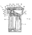
- the accuracy of the inclination between the vibration surface of the horn vibrator and the sheet including the mesh portion can be increased without increasing the number of members, It can be atomized stably.
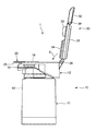
- FIG. 5A is a view showing a state where the mesh nebulizer is assembled (assembled state) as viewed from the right side.
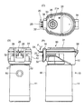
- FIG. 5 (B) and 5 (C) are views showing the mesh type nebulizer of FIG. 5 (A) as viewed from the front and from above, respectively. It is a figure which shows the longitudinal cross-section when the mesh type nebulizer in an assembly state is seen from the right side. It is a figure which expands and shows the vicinity of the replacement member in FIG. It is a perspective view of the cut surface in the longitudinal cross-section of the mesh type nebulizer in FIG.
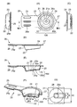
- FIG. 8A is a plan view showing the replacement member.
- FIGS. 8B, 8C, and 8D are views showing the replacement member as viewed from the left side, the right side, and the lower side in FIG. 8A, respectively.
- FIG. 8E is a diagram illustrating a cross-section taken along line VIIIE-VIIIE in FIG.
- FIG. 8F is a perspective view of a cut surface when the replacement member is cut along the line VIIIE-VIIIE in FIG.
- FIG. 8G is an enlarged view showing the vicinity of the mesh portion in FIG. It is a figure which shows the block structure of the control system mounted in the main body of the said mesh-type nebulizer. It is a figure which illustrates the aspect which a user uses the said mesh type nebulizer.
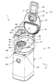
- FIG. 1 shows a mesh nebulizer according to an embodiment of the present invention (the whole is denoted by reference numeral 1) viewed obliquely in an exploded state.
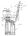
- FIG. 2 shows a longitudinal section when the mesh nebulizer 1 in the exploded state of FIG. 1 is viewed from the right side (the direction indicated by the arrow A in FIG. 1).
- the mesh nebulizer 1 includes a main body lower portion 11 having a substantially quadrangular prism-like outer shape, and an approximately mounted and detachably fitted to the main body lower portion 11 from above. And a main body upper part 12 having an elliptical columnar outer shape.
- the main body lower part 11 and the main body upper part 12 constitute a main body 10.
- a power switch 50 for turning on / off the power supply of the nebulizer 1 is provided on the front surface of the lower part 11 of the main body.
- LED lamps 51 and 52 for notifying the operation state of the nebulizer 1 are provided at the upper left corner and the upper right corner on the front side of the upper surface of the lower body 11, respectively.
- a control system, which will be described later, is mainly mounted inside the lower body 11.
- a recess 16 having a substantially circular planar shape opened upward is provided in the front half of the upper surface of the main body upper portion 12 so as to receive an exchange member 20 described later.
- the recess 16 includes a bottom surface 16 b inclined with respect to the longitudinal direction (vertical direction) of the main body 10, and a side surface 16 c that is connected to the bottom surface 16 b and gradually opens upward. have.
- the diameter from the recess 16 to a specific direction in this example, the front side
- a groove 16e extending outward in the direction is provided.
- a groove 16f extending radially outward from the recess 16 to the rear side in this example is provided around the upper edge of the recess 16 so that a tip protrusion 27 of the replacement member 20 described later is fitted. Yes. Further, as shown in FIG. 2, a packing 29 is provided so as to surround and contact a side surface 16 c of the recess 16 of the main body 10 in a circumferential direction with a side wall 23 of the replacement member 20 described later.
- a vibration part 40 is provided inside the upper part 12 of the main body.
- the vibrating portion 40 is disposed at a position corresponding to the bottom surface 16b of the concave portion 16 and is disposed horizontally at a position spaced downward from the concave portion 16, and a vibrating surface 43 facing upward,
- a horn 42 that is disposed between the acoustic transducer 41 and the vibration surface 43 and that amplifies the vibration of the ultrasonic transducer 41 and transmits the vibration to the vibration surface 43 is included.
- a driving voltage for the ultrasonic transducer 41 is supplied from the lower body 11 through a contact electrode provided between the upper body 12 and the lower body 11.
- a liquid storage portion 17 having a substantially semicircular planar shape is provided in a region corresponding to the latter half of the upper surface of the upper portion 12 of the main body.
- the liquid storage unit 17 has a bottom surface 17 b that gradually becomes shallower toward the front side.
- a liquid supply path 18 for supplying a liquid (chemical solution) from the liquid storage unit 17 toward the vibration surface 43 of the vibration unit 40 is provided continuously to the front side portion of the liquid storage unit 17.
- the liquid storage part 17 and the liquid supply path 18 constitute a liquid supply part. In the disassembled state of FIGS. 1 and 2, the liquid storage unit 17 is open upward. Therefore, the user can put the chemical into the liquid storage unit 17 from above.
- a substantially oval plate-like cover 31 is coupled to the rear edge of the upper surface of the main body upper portion 12 so as to be rotatable with respect to the main body upper portion 12 via a hinge 38 as indicated by an arrow B. .
- the cover 31 has a protrusion 33 having a substantially cylindrical shape on the side facing the upper surface of the main body upper portion 12 and a mesa portion having a substantially semicircular planar shape corresponding to the planar shape of the liquid storage portion 17. 34.
- the protrusion 33 functions to position the replacement member 20.
- the mesa unit 34 blocks the upper part of the liquid storage unit 17 and prevents the liquid medicine from overflowing from the liquid storage unit 17.
- the cover 31 is rotatable with respect to the cover 31 via a hinge 39 as indicated by an arrow C, and is substantially U-shaped. Are connected.
- the engagement frame 32 is rotated toward the front surface of the main body upper portion 12 in a state where the cover 31 is closed with respect to the main body upper portion 12, the engagement frame 32 and the engagement protrusion 19 provided on the upper front surface of the main body upper portion 12 It is configured to engage.
- the cover 31 is fixed to the main body upper portion 12 in a closed state.
- These cover 31 and engagement frame 32 constitute a cap member 30. With this configuration, the user can easily open and close the cap member 30 with respect to the main body 10 (main body upper portion 12), and can prevent the cap member 30 from being lost.
- FIG. 1 and 2 show an exchange member 20 configured separately from the main body 10 and the cap member 30.
- the replacement member 20 is detachably attached to the concave portion 16 of the main body upper portion 12 in advance when the nebulizer 1 is used.
- the replacement member 20 includes a flat sheet 21 that should be opposed to the vibration surface 43 (see FIGS. 1 and 2), and a lower surface of the periphery of the sheet 21.
- a flat annular bottom plate portion 22 that supports and has an inner diameter larger than the diameter of the vibration surface 43, and a side wall that is connected to the outer edge of the bottom plate portion 22 and faces the side surface 16c of the recess 16 (see FIGS. 1 and 2). It includes a portion 23 and a flange portion 24 that is continuous with the upper edge of the side wall portion 23 and extends radially outward around the upper edge.
- the sheet 21 is attached to the upper surface of the bottom plate portion 22 by adhesion or welding.
- a mesh portion 21 a is formed in a substantially central region of the sheet 21.
- the mesh portion 21a and the bottom plate portion 22 of the replacement member 20 are side wall portions 23 so as to correspond to the bottom surface 16b (see FIG. 2) of the concave portion 16 of the main body 10. And a substantially flat inclined surface that is inclined with respect to a plane (horizontal plane) orthogonal to the center 23c. Moreover, the side wall part 23 of the replacement member 20 is gradually opened as it corresponds to the side surface 16c (refer FIG. 2) of the recessed part 16 of the main body 10 as it goes upwards.
- a protruding portion 22p that protrudes (projects) inward in the radial direction from the bottom plate portion 22 and reaches just below a ring member 26 to be described later and stops.
- the support frame 100 is configured by the bottom plate portion 22 and the protruding portion 22p. With this configuration, the sheet 21 can be kept as flat as possible. Furthermore, the protrusion 22p functions as a part of the support frame 100 to maintain the seat 21 in an inclined state with respect to the vibration surface 43, as will be described later.
- the protrusion 22p is uniformly and continuously integrated with the same material as the bottom plate 22. Thereby, the vibration surface 43 and the mesh part 21a can be accurately inclined in the mounted state without increasing the number of members for inclination. Therefore, the configuration becomes simpler.
- FIG. 8G shows an enlarged view of the vicinity of the mesh portion 21a in FIG.
- a flat annular ring member 26 having a thickness of about 400 ⁇ m is attached to the position surrounding the mesh portion 21a on the sheet 21 by adhesion or welding.
- the ring member 26 has an outer diameter smaller than the inner diameter of the bottom plate portion 22. The ring member 26 is attached to keep the mesh portion 21a as flat as possible and adjust the natural frequency of the seat 21 including the mesh portion 21a.
- the inner diameter ID of the ring member 26 is set to 2.2 mm, and the outer dimension OD is set to 6.0 mm.
- the mesh portion 21a is located in the opening 26o of the ring member 26 so that the atomized chemical liquid can be discharged through the above-described through hole.
- the knob portion 25 extends beyond the flange portion 24 in a specific direction (around a center 23 c of the side wall portion 23). In this example, it extends radially outward (to the left in FIGS. 8A and 8E).
- the knob 25 is provided for the convenience of picking up and down with the thumb and index finger, for example.
- the knob portion 25 is provided with unevenness 25p for preventing slipping.
- the tip protrusion 27 extends beyond the flange portion 24 in the direction opposite to the direction in which the knob portion 25 extends, in this example, FIGS. 8A and 8E. Projecting to the right.
- the knob 25 and the tip protrusion 27 enable the positioning of the replacement member 20 in the circumferential direction with respect to the recess 16 when the user mounts the replacement member 20 in the recess 16 of the main body upper portion 12.
- all elements constituting the replacement member 20 are made of synthetic resin. Therefore, the replacement member 20 can be manufactured at low cost.
- Synthetic resins constituting the exchange member 20 include polyamide resins, polyesters, syndiopolystyrenes, polysulfones, polyether sulfones, polyether ether ketones, polyether imides, polyamide imides, PPS (polyphenylene sulfide), epoxies, phenols, and polyimides. Etc.
- a user who intends to use the mesh nebulizer 1 has a concave portion 16 having a shape opened upward from the main body 10 with the cap member 30 open to the main body 10 as shown in FIGS. 1 and 2.
- the replacement member 20 having the mesh portion 21a is attached.
- the replacement member 20 When the replacement member 20 is mounted, the user holds the picking portion 25 with his / her hand (for example, pinching the picking portion 25 up and down with the thumb and the index finger) to the mesh portion 21 a of the replacement member 20.
- the replacement member 20 can be easily attached to the recess 16 of the main body 10 without touching with a finger.
- the user aligns the tip protrusion 27 and the knob 25 of the replacement member 20 with the groove 16f and the groove 16e around the upper edge of the recess 16, respectively. Positioning in the circumferential direction is possible.
- the side surface of the concave portion 16 of the main body 10 is gradually opened upward.
- the side wall part 23 of the replacement member 20 is gradually opened as it corresponds to the side surface 16c (refer FIG. 2) of the recessed part 16 of the main body 10 as it goes upwards. Therefore, if the user places the replacement member 20 around the recess 16 when the replacement member 20 is mounted, the side wall portion 23 of the replacement member 20 is guided downward by the side surface 16 c of the recess 16.
- the bottom surface 16b of the concave portion 16 of the main body 10 is inclined with respect to the longitudinal direction (vertical direction) of the main body 10, and the mesh of the replacement member 20 so as to correspond to the bottom surface 16b of the concave portion 16 of the main body 10.
- the part 21 a and the bottom plate part 22 are inclined with respect to the center 23 c of the side wall part 23. Therefore, if the user places the replacement member 20 around the recess 16 when the replacement member 20 is mounted, the mesh portion 21 a and the bottom plate portion 22 of the replacement member 20 correspond to the bottom surface 16 b of the recess 16 of the main body 10. To be guided. Therefore, positioning of the replacement member 20 in the circumferential direction and the vertical axis direction with respect to the recess 16 is assisted.
- the bottom plate portion 22 (supporting the periphery of the mesh portion 21 a) of the replacement member 20 faces the bottom surface 16 b of the recess 16, and the side wall portion 23 of the replacement member 20 is recessed. 16 faces the side surface 16c. Therefore, the user can easily attach the replacement member 20 to the recess 16 of the main body 10. This state is called a wearing state.
- the mesa part 34 of the cover 31 closes the upper part of the liquid storage part 17 and prevents the liquid medicine from overflowing from the liquid storage part 17.
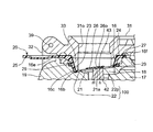
- FIG. 7A is an enlarged view showing the vicinity of the replacement member in FIG. 7B is a perspective view of a cut surface in a longitudinal section of the mesh nebulizer in FIG.
- the protrusion 33 provided to protrude toward the main body upper portion 12 of the cap member 30 presses the bottom plate portion 22 of the replacement member 20 toward the bottom surface 16 b of the recess 16, thereby The replacement member 20 is positioned with respect to the vertical axis direction. Accordingly, the mesh portion 21a of the replacement member 20 is positioned to face the vibration surface 43 of the vibration portion 40 disposed at a position corresponding to the bottom surface 16b of the recess 16.
- the sheet 21 including the mesh portion 21 a is disposed so as to be inclined and opposed to the vibration surface 43 of the main body 10, and abuts on the first portion m of the periphery of the vibration surface 43.
- the protrusion 22 p of the support frame 100 abuts on the second portion n facing the first portion m of the periphery of the vibration surface 43 and maintains the seat 21 in an inclined state with respect to the vibration surface 43.
- the sheet 21 including the mesh portion 21a is directly positioned with respect to the vibration surface 43 at the first portion m, and the protrusion 22p of the support frame 100 with respect to the vibration surface 43 at the second portion n. It is positioned indirectly via.
- the accuracy of the inclination between the vibration surface 43 of the ultrasonic transducer 41 and the sheet 21 including the mesh portion 21a is increased without increasing the number of members. Accordingly, since the mesh portion 21a is inclined with respect to the vibration surface 43 with high accuracy during use, the distance between the mesh portion 21a and the vibration surface 43 can be optimized in any part of the mesh portion 21a. Therefore, it becomes possible to always atomize the liquid stably. Note that the sheet 21 including the mesh portion 21 a is in direct or indirect contact with the vibration surface 43 because the periphery of the vibration surface 43 has little influence on the vibration of the vibration surface 43.
- the protrusion 22 p is in contact with the second portion n at the periphery of the vibration surface 43 as a part of the support frame 100. As a result, the protrusion 22 p reliably contacts the second portion n at the periphery of the vibration surface 43, and the mesh portion 21 a can be reliably inclined with respect to the vibration surface 43.
- the packing 29 is provided so as to be in contact with the side surface 16c of the recess 16 of the main body 10 so as to surround the side wall portion 23 of the replacement member 20 in the circumferential direction. Therefore, thanks to the packing 29, the chemical solution supplied between the vibration surface 43 and the mesh portion 21 a can be used between the side surface 16 c of the concave portion 16 and the side wall portion 23 of the replacement member 20 in the following use. Can be prevented from overflowing to the outside.
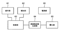
- FIG. 9 shows a block configuration of a control system mounted on the main body 10 of the mesh nebulizer 1.
- the mesh nebulizer 1 includes an operation unit 61, a notification unit 62, a control unit 63, an oscillation frequency generation unit 64, an atomization unit 65, and a power supply unit 66.
- the operation unit 61 includes the power switch 50 shown in FIG.
- the notification unit 62 includes the LED lamps 51 and 52 shown in FIG. 1, and may further include a buzzer (not shown).
- the oscillation frequency generation unit 64 applies an alternating drive voltage to the atomization unit 65 based on a control signal from the control unit 63. This drive voltage is output over a certain output time after the power switch 50 is pressed, for example.
- the output time can be measured by a timer (not shown).
- the atomization part 65 includes the vibration part 40 and the mesh part 21a of the replacement member 20 shown in FIG.
- the AC drive voltage from the oscillation frequency generation unit 64 is applied to the ultrasonic transducer 41 of the vibration unit 40 that forms the atomization unit 65.
- the vibration of the ultrasonic transducer 41 is amplified by the horn 42 and transmitted to the vibration surface 43.
- the vibration surface 43 vibrates, the chemical solution supplied to the gap between the vibration surface 43 and the mesh portion 21a is atomized and ejected through the mesh portion 21a.
- the control unit 63 includes a CPU (Central Processing Unit) and sends a signal to the atomization unit 65 via the oscillation frequency generation unit 64 to control the atomization amount, the continuous operation time, and the like. In addition, the control unit 63 notifies that the power is turned on when the LED lamp 51 is turned on, the battery capacity is insufficient due to the blinking of the LED lamp 52, and the like.
- the power supply unit 66 includes a battery (for example, a DC3V chargeable / dischargeable secondary battery), and supplies power to each unit of the control system.
- the mesh nebulizer When using the mesh nebulizer 1, the user puts a chemical solution in the liquid storage part 17 of the main body upper part 12 in advance. Then, as shown in FIG. 10, the user detachably attaches, for example, a mouthpiece 80 to the opening 31o in the protrusion 33 of the cover 31 in the assembled state. As a result, the mesh portion 21a of the replacement member 20 is in a state of being inclined with high accuracy and facing the vibration surface 43 of the main body 10.
- the replacement member 20 is typically disposable after being used in the mesh nebulizer 1. In that case, the user does not need to clean, disinfect, and dry the replacement member 20 including the mesh portion 21a. Therefore, care is easy for the user.
- the replacement member 20 is configured to be separated from the main body 10 and the cap member 30, it can be relatively small and manufactured at low cost. Therefore, the cost burden for the replacement member 20 can be reduced for the user.
- an inhalation mask that covers the face of the user 99 may be attached.
- the liquid medicine is supplied from the liquid storage part 17 constituting the liquid supply part through the liquid supply path 18 toward the vibration surface 43 of the vibration part 40. Is supplied. That is, the chemical solution is supplied between the vibration surface 43 and the mesh portion 21a.
- a driving voltage is applied to the ultrasonic transducer 41 of the vibrating unit 40 and the vibrating surface 43 is vibrated.
- medical solution 90 is atomized and ejected through the mesh part 21a (more correctly, the some through-hole which penetrates the sheet
- the protrusion 22p is uniformly and continuously integrated with the same material as the bottom plate 22, but the present invention is not limited to this.
- the protruding portion 22p may be configured as a separate body from the bottom plate portion 22, and may be attached to the bottom plate portion 22 by, for example, welding or adhesion.
- the bottom plate portion 22 and the protruding portion 22p can be manufactured separately. Accordingly, the support frame 100 and thus the replacement member 20 can be easily manufactured.
Landscapes
- Health & Medical Sciences (AREA)
- Engineering & Computer Science (AREA)
- Anesthesiology (AREA)
- Biomedical Technology (AREA)
- Heart & Thoracic Surgery (AREA)
- Hematology (AREA)
- Life Sciences & Earth Sciences (AREA)
- Animal Behavior & Ethology (AREA)
- General Health & Medical Sciences (AREA)
- Public Health (AREA)
- Veterinary Medicine (AREA)
- Bioinformatics & Cheminformatics (AREA)
- Pulmonology (AREA)
- Special Spraying Apparatus (AREA)
Abstract
本発明の、メッシュ部(21a)を通して液体を霧化して噴出するメッシュ式ネブライザ(1)は、上方へ面した振動面(43)を有する振動部(40)と、振動部(40)の振動面(43)上へ向けて液体を供給する給液部(17)と、メッシュ部(21a)を含むシート(21)と、シート(21)の周縁を支持する支持枠(100)とを含み、メッシュ部(21a)を含むシート(21)は、振動面(43)に対して傾斜して対向するように配置され、振動面(43)の周縁のうち第1の部分(m)と当接し、支持枠(100)の一部(22p)は、振動面(43)の周縁のうち第1の部分(m)と対向する第2の部分(n)と当接して、振動面(43)に対してシート(21)を傾斜した状態に維持する。
Description
この発明はメッシュ式ネブライザに関し、より詳しくは、振動面とメッシュ部との間に供給された液体を、メッシュ部を通して霧化して噴出するメッシュ式ネブライザに関する。
従来、この種のメッシュ式ネブライザとしては、例えば特許文献1(特開2014-4208号公報)に開示されているように、本体にホーン振動子を備え、本体に対して着脱可能および開閉(回動)可能に取り付けられたメッシュキャップを備えたものが知られている。本体に対してメッシュキャップが取り付けられ、閉じられた状態では、ホーン振動子の振動面(先端部の表面)とメッシュキャップに設けられた薄板状のメッシュ部とが対向する。この状態で、振動面とメッシュ部との間に薬液が供給されるとともに、上記ホーン振動子に駆動電圧が印加されて振動面が振動される。これにより、上記メッシュ部を通して上記薬液が霧化されて噴出する。
上記メッシュ式ネブライザでは、ホーン振動子の振動面をメッシュ部の入口面(上記振動面に対向する面)に対して傾斜させることで、メッシュ部のいずれかの部位において入口面と振動面との間隔が最適となるように構成されている。
しかしながら、上記メッシュ式ネブライザでは、メッシュ部が、振動面の直径よりも大きい外径をもつ補強部で支持され、振動面のうち周縁の1箇所のみで振動面に当接されている。補強部は振動面から離間している。このため、メッシュ部を例えば合成樹脂からなるシートで構成すると、シートが撓んで、振動面とメッシュ部(の入口面)との傾斜の精度が不十分になるという問題がある。また、ホーン振動子の振動面とメッシュ部の入口面とを所定の角度だけ傾斜させるためには複数の部材が必要となる。
そこで、この発明の課題は、部材数を増加させることなしにホーン振動子の振動面とメッシュ部を含むシートとの傾斜の精度を高めることができ、液体を安定して霧化することができるメッシュ式ネブライザを提供することにある。
上記課題を解決するため、この発明のメッシュ式ネブライザは、
メッシュ部を通して液体を霧化して噴出するメッシュ式ネブライザであって、
上方へ面した振動面を有する振動部と、
上記振動部の上記振動面上へ向けて液体を供給する給液部と、
メッシュ部を含むシートと、
上記シートの周縁を支持する支持枠とを含み、
上記メッシュ部を含むシートは、上記振動面に対して傾斜して対向するように配置され、上記振動面の周縁のうち第1の部分と当接し、
上記支持枠の一部は、上記振動面の周縁のうち第1の部分と対向する第2の部分と当接して、上記振動面に対して上記シートを傾斜した状態に維持することを特徴とする。
メッシュ部を通して液体を霧化して噴出するメッシュ式ネブライザであって、
上方へ面した振動面を有する振動部と、
上記振動部の上記振動面上へ向けて液体を供給する給液部と、
メッシュ部を含むシートと、
上記シートの周縁を支持する支持枠とを含み、
上記メッシュ部を含むシートは、上記振動面に対して傾斜して対向するように配置され、上記振動面の周縁のうち第1の部分と当接し、
上記支持枠の一部は、上記振動面の周縁のうち第1の部分と対向する第2の部分と当接して、上記振動面に対して上記シートを傾斜した状態に維持することを特徴とする。
本明細書で、「メッシュ部」とは、シートを貫通する複数の貫通孔を有し、これらの貫通孔を通過させて液体を霧化するための要素を意味する。
この発明のメッシュ式ネブライザでは、上記メッシュ部を含むシートは、上記振動面に対して傾斜して対向するように配置され、上記振動面の周縁のうち第1の部分と当接する。また、上記支持枠の一部は、上記振動面の周縁のうち第1の部分と対向する第2の部分と当接して、上記振動面に対して上記シートを傾斜した状態に維持する。したがって、上記メッシュ部を含むシートは、上記第1の部分で上記振動面に対して直接位置決めされるとともに、上記第2の部分で上記振動面に対して上記支持枠の上記一部を介して間接的に位置決めされる。この結果、部材数を増加させることなしに、上記ホーン振動子の振動面と上記メッシュ部を含むシートとの傾斜の精度が高まる。
使用時には、給液部が振動部の振動面上へ向けて液体を供給する。これにより、振動面とメッシュ部との間に液体が供給される。そして、振動部に駆動電圧が印加されて振動面が振動される。これにより、メッシュ部(より正確には、シートを貫通する複数の貫通孔)を通して上記液体が霧化されて噴出する。ここで、振動面に対してメッシュ部を精度良く傾斜させているので、メッシュ部のいずれかの部位において、メッシュ部と振動面との間隔を最適にすることができる。したがって、液体を常に安定して霧化することが可能となる。なお、上記振動面に対して上記メッシュ部を含むシートが直接または間接に当接しているのは、上記振動面の周縁であるから、上記振動面の振動に対する影響は少ない。
一実施形態のメッシュ式ネブライザは、
上方へ向かって開いた形状の凹部を有する本体を備え、
上記本体は、
上記凹部の底面に相当する位置に配された上記振動面を有する上記振動部を含み、
上記本体の上部を開閉可能に覆うキャップ部材と、
上記本体および上記キャップ部材から分離して構成され、このネブライザが使用される際に予め上記本体の上記凹部に着脱可能に装着される交換部材とを備え、
上記交換部材は、上記メッシュ部を含む上記シートと、上記シートの周縁を支持する上記支持枠とを含むことを特徴とする。
上方へ向かって開いた形状の凹部を有する本体を備え、
上記本体は、
上記凹部の底面に相当する位置に配された上記振動面を有する上記振動部を含み、
上記本体の上部を開閉可能に覆うキャップ部材と、
上記本体および上記キャップ部材から分離して構成され、このネブライザが使用される際に予め上記本体の上記凹部に着脱可能に装着される交換部材とを備え、
上記交換部材は、上記メッシュ部を含む上記シートと、上記シートの周縁を支持する上記支持枠とを含むことを特徴とする。
この一実施形態のメッシュ式ネブライザを使用しようとするユーザは、本体に対してキャップ部材が開いた状態で、本体の上方へ向かって開いた形状の凹部に、メッシュ部を有する交換部材を着脱可能に装着する。これにより、交換部材のメッシュ部が本体の振動面に対して精度良く傾斜して対向する状態となる。この交換部材は、上記メッシュ式ネブライザにおいて使用された後、典型的には、使い捨てされる。その場合、ユーザは、メッシュ部を含む交換部材を洗浄、消毒、乾燥する必要がない。したがって、ユーザにとって、手入れが簡単になる。また、上記交換部材は、上記本体および上記キャップ部材から分離して構成されているので、比較的小型で安価に製造され得る。したがって、ユーザにとって、交換部材のための費用負担が少なくて済む。
一実施形態のメッシュ式ネブライザでは、
上記支持枠は、上記シートの周縁の下面を支持し、上記振動面の直径よりも大きい内径をもつ平坦な環状の底板部と、この底板部から径方向内向きに突起した突起部とを含み、
上記突起部は、上記支持枠の上記一部として、上記振動面の周縁の上記第2の部分に当接することを特徴とする。
上記支持枠は、上記シートの周縁の下面を支持し、上記振動面の直径よりも大きい内径をもつ平坦な環状の底板部と、この底板部から径方向内向きに突起した突起部とを含み、
上記突起部は、上記支持枠の上記一部として、上記振動面の周縁の上記第2の部分に当接することを特徴とする。
この一実施形態のメッシュ式ネブライザでは、上記振動面の周縁の上記第2の部分に対して上記突起部が確実に当接して、上記振動面に対して上記メッシュ部を確実に傾斜させることができる。
一実施形態のメッシュ式ネブライザでは、上記突起部は、上記底板部と共通の材料で均質に連続して一体化されていることを特徴とする。
ここで、「共通の材料で均質に連続して一体化」されているとは、例えば、複数の部分が射出成形によって一体成形されているような場合を意味する。
この一実施形態のメッシュ式ネブライザでは、傾斜させるための部材を増加させることなしに、上記振動面と上記メッシュ部とを精度良く傾斜させることができる。したがって、構成がより簡素となる。
一実施形態のメッシュ式ネブライザでは、上記突起部は、上記底板部とは別体として構成され、上記底板部に対して取り付けられていることを特徴とする。
ここで、「別体として構成され」「取り付けられている」とは、例えば、複数の部分が溶着または接着によって一体化されているような場合を意味する。
この一実施形態のメッシュ式ネブライザでは、上記底板部と上記突起部とを別々に製造することができる。したがって、上記支持枠、したがって上記交換部材の製造が容易となるとともに製造コストを削減することができる。
一実施形態のメッシュ式ネブライザでは、
上記シートの上面に、上記底板部の内径よりも小さい外径をもつ平坦なリング部材が取り付けられていることを特徴とする。
上記シートの上面に、上記底板部の内径よりも小さい外径をもつ平坦なリング部材が取り付けられていることを特徴とする。
この一実施形態のメッシュ式ネブライザでは、上記リング部材によって上記メッシュ部がより平坦に維持される。したがって、上記振動面と上記メッシュ部とをより精度良く傾斜させることができる。
以上より明らかなように、この発明のメッシュ式ネブライザによれば、部材数を増加させることなしにホーン振動子の振動面とメッシュ部を含むシートとの傾斜の精度を高めることができ、液体を安定して霧化することができる。
以下、この発明の実施の形態を、図面を参照しながら詳細に説明する。
(メッシュ式ネブライザの構成要素)
図1はこの発明の一実施形態のメッシュ式ネブライザ(全体を符号1で示す。)を分解状態で斜めから見たところを示している。図2は図1の分解状態にあるメッシュ式ネブライザ1を右側方(図1中に矢印Aで示す方向)から見たときの縦断面を示している。
図1はこの発明の一実施形態のメッシュ式ネブライザ(全体を符号1で示す。)を分解状態で斜めから見たところを示している。図2は図1の分解状態にあるメッシュ式ネブライザ1を右側方(図1中に矢印Aで示す方向)から見たときの縦断面を示している。
これらの図1,図2に示すように、このメッシュ式ネブライザ1は、略四角柱状の外形を有する本体下部11と、この本体下部11に対して上方から着脱可能に嵌め込んで装着された略楕円柱状の外形をもつ本体上部12とを備えている。本体下部11と本体上部12とで本体10が構成されている。
図1に示すように、本体下部11の前面には、このネブライザ1の電源をオン、オフするための電源スイッチ50が設けられている。また、本体下部11の上面のうち、前面側の左上隅、右上隅には、それぞれこのネブライザ1の動作状態を報知するためのLEDランプ51,52が設けられている。本体下部11の内部には、主に後述の制御系が搭載されている。
本体上部12の上面のうち前半分の領域に、後述の交換部材20を受けるように、上方へ向かって開いた略円形の平面形状をもつ凹部16が設けられている。この凹部16は、図2に示すように、本体10の縦軸方向(鉛直方向)に対して傾斜した底面16bと、この底面16bに連なり、上方へ向かうに連れて次第に開いている側面16cとを有している。また、図1に示すように、凹部16の上縁の周りに、後述の交換部材20の摘まみ部25が嵌合するように、凹部16から特定の方向(この例では前面側)へ径方向外向きに延在する溝16eが設けられている。さらに、凹部16の上縁の周りに、後述の交換部材20の先端突起27が嵌合するように、凹部16からこの例では後面側へ径方向外向きに延在する溝16fが設けられている。さらに、図2中に示すように、本体10の凹部16の側面16cに、後述の交換部材20の側壁部23を周方向に取り囲んで接するように、パッキン29が設けられている。
本体上部12の内部には、凹部16に対応する位置に、振動部40が設けられている。この振動部40は、凹部16から下方に離間した位置に配された超音波振動子41と、凹部16の底面16bに相当する位置に水平に配され、上方へ面した振動面43と、超音波振動子41と振動面43との間に配され、超音波振動子41の振動を増幅するとともに振動面43へ伝達するホーン42とを含んでいる。超音波振動子41に対する駆動電圧は、本体上部12と本体下部11との間に設けられた接点電極を介して、本体下部11から供給されるようになっている。
また、図1に示すように、本体上部12の上面のうち後半分の領域に、略半円形の平面形状をもつ貯液部17が設けられている。この貯液部17は、図2に示すように、前面側へ向かうに連れて次第に浅くなる底面17bを有している。また、この貯液部17の前面側部分に連なって、貯液部17から振動部40の振動面43上へ向けて液体(薬液)を供給するための給液路18が設けられている。貯液部17と給液路18とで給液部が構成されている。図1,図2の分解状態では、貯液部17は上方へ向かって開いている。したがって、ユーザは、貯液部17に上方から薬液を入れることができる。
本体上部12の上面のうち後面側の縁には、本体上部12に対して蝶番38を介して矢印Bで示すように回動可能に、略楕円形の板状のカバー31が連結されている。このカバー31は、本体上部12の上面に対向する側に、略円筒形に突出した形状をもつ突起部33と、貯液部17の平面形状と対応する略半円形の平面形状を有するメサ部34とを有している。後述のように、本体上部12に対してカバー31が閉じられ、このネブライザ1が組み立てられた状態では、突起部33は、交換部材20を位置決めするように機能する。また、メサ部34は、貯液部17の上部を塞いで、貯液部17から薬液が溢れるのを防止する。
また、カバー31の先端(蝶番38とは反対側の端部)には、カバー31に対して蝶番39を介して矢印Cで示すように回動可能に、略コの字の係合枠32が連結されている。この係合枠32は、本体上部12に対してカバー31が閉じられた状態で、本体上部12の前面へ向かって回転されると、本体上部12の前面上部に設けられた係合突起19と係合するように構成されている。これにより、本体上部12に対してカバー31が閉じられた状態で固定される。これらのカバー31と係合枠32とでキャップ部材30が構成されている。この構成により、ユーザは、本体10(本体上部12)に対してキャップ部材30を容易に開閉できるとともに、キャップ部材30の紛失を防止できる。
図1,図2中には、本体10およびキャップ部材30から分離して構成された交換部材20が示されている。この交換部材20は、このネブライザ1が使用される際に予め本体上部12の凹部16に着脱可能に装着される。
図8(A)~図8(G)は、交換部材20の構成を詳細に示している。図8(A)及び図8(E)に示すように、交換部材20は、振動面43(図1,図2参照)に対向すべき平坦なシート21と、このシート21の周縁の下面を支持し、振動面43の直径よりも大きい内径を有する平坦な環状の底板部22と、この底板部22の外縁に連なり、凹部16の側面16c(図1,図2参照)に対向すべき側壁部23と、この側壁部23の上縁に連なり、その上縁の周りに径方向外向きに広がるフランジ部24とを含んでいる。シート21は、底板部22の上面に接着または溶着により取り付けられている。シート21のうち略中央の領域においてメッシュ部21aが形成されている。
図8(E)及び図8(F)に示すように、本体10の凹部16の底面16b(図2参照)に対応するように、交換部材20のメッシュ部21a及び底板部22は側壁部23の中心23cに対して直交する面(水平面)に対して傾斜する略平坦な傾斜面を有している。また、本体10の凹部16の側面16c(図2参照)に対応するように、交換部材20の側壁部23は上方へ向かうに連れて次第に開いている。また、底板部22から径方向内向きに突起(突出)し、後述するリング部材26の直下に達して止まっている突起部22pが設けられている。底板部22と突起部22pとで支持枠100が構成されている。この構成により、シート21をできるだけ平坦に維持することができる。さらに、突起部22pは、後述するように、支持枠100の一部として、振動面43に対してシート21を傾斜した状態に維持するために機能する。
また、突起部22pは、底板部22と共通の材料で均質に連続して一体化されている。これにより、傾斜させるための部材を増加させることなしに、装着状態において振動面43とメッシュ部21aとを精度良く傾斜させることができる。したがって、構成がより簡素となる。
図8(G)は、図8(A)におけるメッシュ部21aの近傍を拡大して示している。この例では、メッシュ部21aは、厚さ30μm程度のシート21において、一辺の寸法X=1.5mmの正方形の領域に、直径3μm程度の図示しない多数の貫通孔が設けられて構成されている。シート21上でメッシュ部21aを取り囲む位置に、厚さ400μm程度の平坦な円環状のリング部材26が接着または溶着により取り付けられている。ここで、リング部材26は、底板部22の内径よりも小さい外径を有する。このリング部材26は、メッシュ部21aをできるだけ平坦に維持するとともに、メッシュ部21aを含むシート21の固有振動数を調節するために取り付けられている。この例では、リング部材26の内径寸法ID=2.2mm、外形寸法OD=6.0mmに設定されている。メッシュ部21aは、上述の貫通孔を通して霧化された薬液を放出できるように、リング部材26の開口26o内に位置している。
また、図8(A)及び図8(E)に示すように、この交換部材20では、フランジ部24を越えて、摘まみ部25が、側壁部23の中心23cの周りに関して特定の方向(この例では、図8(A)、図8(E)において左方)へ径方向外向きに延在している。この摘まみ部25は、ユーザが交換部材20を手で持つ際に、例えば親指と人指し指で上下に挟んで摘まむ便宜のために設けられている。摘まみ部25には、滑り止めのための凹凸25pが設けられている。さらに、この交換部材20では、フランジ部24を越えて、先端突起27が、摘まみ部25が延在するのとは反対の方向へ、この例では図8(A)、図8(E)において右方へ突出している。摘まみ部25および先端突起27は、ユーザが交換部材20を本体上部12の凹部16に装着する際に、凹部16に対する交換部材20の周方向の位置決めを可能にする。
この例では、交換部材20をなす全ての要素は合成樹脂からなっている。したがって、交換部材20を安価に製造できる。交換部材20をなす合成樹脂としては、ポリアミド系樹脂、ポリエステル、シンジオ型ポリスチレン、ポリサルフォン、ポリエーテルサルフォン、ポリエーテルエーテルケトン、ポリエーテルイミド、ポリアミドイミド、PPS(polyphenylene sulfide)、エポキシ、フェノール、ポリイミドなどが挙げられる。
(メッシュ式ネブライザの組み立て)
このメッシュ式ネブライザ1を使用しようとするユーザは、図1および図2に示したように本体10に対してキャップ部材30が開いた状態で、本体10の上方へ向かって開いた形状の凹部16に、図2中に矢印Dで示すように、メッシュ部21aを有する交換部材20を装着する。
このメッシュ式ネブライザ1を使用しようとするユーザは、図1および図2に示したように本体10に対してキャップ部材30が開いた状態で、本体10の上方へ向かって開いた形状の凹部16に、図2中に矢印Dで示すように、メッシュ部21aを有する交換部材20を装着する。
この交換部材20の装着時に、ユーザは、自らの手で摘まみ部25を持つ(例えば親指と人指し指で摘まみ部25を上下に挟んで摘まむ)ことによって、交換部材20のメッシュ部21aに指で触れること無しに、本体10の凹部16に交換部材20を容易に装着することができる。
また、この交換部材20の装着時に、ユーザが交換部材20の先端突起27、摘まみ部25をそれぞれ凹部16の上縁の周りの溝16f、溝16eに合わせることによって、凹部16に対する交換部材20の周方向の位置決めが可能となる。
また、既述のように、本体10の凹部16の側面は、上方へ向かうに連れて次第に開いている。また、本体10の凹部16の側面16c(図2参照)に対応するように、交換部材20の側壁部23は上方へ向かうに連れて次第に開いている。したがって、交換部材20の装着時に、ユーザが、凹部16の辺りに交換部材20を載置すれば、凹部16の側面16cによって交換部材20の側壁部23が下方へ案内される。
また、本体10の凹部16の底面16bは本体10の縦軸方向(鉛直方向)に対して傾斜しており、また、本体10の凹部16の底面16bに対応するように、交換部材20のメッシュ部21aおよび底板部22は側壁部23の中心23cに対して傾斜している。したがって、交換部材20の装着時に、ユーザが、凹部16の辺りに交換部材20を載置すれば、交換部材20のメッシュ部21aおよび底板部22は、本体10の凹部16の底面16bに対応するように案内される。したがって、凹部16に対する交換部材20の周方向および縦軸方向の位置決めが助けられる。
これにより、図3および図4に示すように、交換部材20の底板部22(メッシュ部21aの周縁を支持する)が凹部16の底面16bに対向するとともに、交換部材20の側壁部23が凹部16の側面16cに対向する状態となる。したがって、ユーザは、本体10の凹部16に交換部材20を容易に装着できる。この状態を装着状態と呼ぶ。
この装着状態で、ユーザが、本体10に対してキャップ部材30を閉じる。具体的には、ユーザが、図4中に矢印Eで示すように、本体上部12に対してカバー31を閉じる。さらに、本体上部12に対してカバー31が閉じられた状態で、ユーザが、図5(A)中に矢印Fで示すように、係合枠32を本体上部12の前面へ向かって回転させる。すると、係合枠32は、交換部材20の摘まみ部25を越えて、本体上部12の前面上部に設けられた係合突起19と係合する。これにより、本体上部12に対してカバー31が閉じられた状態で固定される。このようにして、メッシュ式ネブライザ1が簡単に組み立てられる。この状態を組み立て状態と呼ぶ。なお、図5(B)、図5(C)は、図5(A)のものをそれぞれ前方、上方から見たところを示している。また、図6は、この組み立て状態にあるメッシュ式ネブライザ1を右側方から見たときの縦断面を示している。
この組み立て状態では、カバー31のメサ部34は、貯液部17の上部を塞いで、貯液部17から薬液が溢れるのを防ぐ。
図7Aは図6における交換部材の近傍を拡大して示す図である。図7Bは図6におけるメッシュ式ネブライザの縦断面での切断面の斜視図である。図7A,図7Bに示すように、キャップ部材30の本体上部12側に突出して設けられた突起部33が交換部材20の底板部22を凹部16の底面16bへ向かって押圧して、本体10の縦軸方向に関して交換部材20を位置決めする。これにより、凹部16の底面16bに相当する位置に配された振動部40の振動面43に対して、交換部材20のメッシュ部21aが対向して位置決めされる。
また、この組み立て状態では、メッシュ部21aを含むシート21は、本体10の振動面43に対して傾斜して対向するように配置され、振動面43の周縁のうち第1の部分mと当接し、支持枠100の突起部22pは、振動面43の周縁のうち第1の部分mと対向する第2の部分nと当接して、振動面43に対してシート21を傾斜した状態に維持する。この構成により、メッシュ部21aを含むシート21は、第1の部分mで振動面43に対して直接位置決めされるとともに、第2の部分nで振動面43に対して支持枠100の突起部22pを介して間接的に位置決めされる。この結果、部材数を増加させることなしに、超音波振動子41の振動面43とメッシュ部21aを含むシート21との傾斜の精度が高まる。したがって、使用時には振動面43に対してメッシュ部21aが精度良く傾斜されるので、メッシュ部21aのいずれかの部位において、メッシュ部21aと振動面43との間隔を最適にすることができる。したがって、液体を常に安定して霧化することが可能となる。なお、振動面43に対してメッシュ部21aを含むシート21が直接または間接に当接しているのは、振動面43の周縁であるから、振動面43の振動に対する影響は少ない。
また、突起部22pは、支持枠100の一部として、振動面43の周縁の第2の部分nに当接している。これにより、振動面43の周縁の第2の部分nに対して突起部22pが確実に当接して、振動面43に対してメッシュ部21aを確実に傾斜させることができる。
また、既述のように、本体10の凹部16の側面16cに、交換部材20の側壁部23を周方向に取り囲んで接するように、パッキン29が設けられている。したがって、このパッキン29のおかげで、次に述べる使用時に、振動面43とメッシュ部21aとの間に供給された薬液が、凹部16の側面16cと交換部材20の側壁部23との間の隙間を通して外部へ溢れるのを防止できる。
図9は、このメッシュ式ネブライザ1の本体10に搭載された制御系のブロック構成を示している。このメッシュ式ネブライザ1は、操作部61と、報知部62と、制御部63と、発振周波数生成部64と、霧化部65と、電源部66とを備えている。操作部61は、この例では、図1中に示した電源スイッチ50を含んでいる。報知部62は、この例では、図1中に示したLEDランプ51,52を含んでおり、さらに図示しないブザーを含んでいてもよい。発振周波数生成部64は、制御部63からの制御信号に基づいて、交流の駆動電圧を霧化部65に印加する。この駆動電圧は、例えば、電源スイッチ50が押されてから或る出力時間にわたって出力される。出力時間の計測は、図示しないタイマによって行うこともできる。霧化部65は、図1中に示した振動部40と交換部材20のメッシュ部21aとを含んでいる。発振周波数生成部64からの交流駆動電圧は、霧化部65をなす振動部40の超音波振動子41に印加される。この超音波振動子41の振動は、ホーン42によって増幅されるとともに振動面43へ伝達される。振動面43が振動すると、振動面43とメッシュ部21aとの間の隙間に供給された薬液がメッシュ部21aを通して霧化されて噴出する。制御部63は、CPU(Central Processing Unit;中央演算処理装置)を含み、発振周波数生成部64を介して霧化部65に信号を送り、霧化量、連続動作時間等を制御する。また、制御部63は、LEDランプ51の点灯によって電源がオンされたこと、LEDランプ52の点滅によって電池の容量が不足していることなどを報知する。電源部66は、電池(例えば、DC3Vの充放電可能な二次電池)を含み、この制御系の各部に電力を供給する。
(メッシュ式ネブライザの使用)
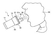
このメッシュ式ネブライザ1を使用する場合、予め、ユーザは、本体上部12の貯液部17に薬液を入れておく。そして、図10に示すように、ユーザは、組み立て状態で、カバー31の突起部33内の開口31oに、例えばマウスピース80を着脱可能に装着する。これにより、交換部材20のメッシュ部21aが本体10の振動面43に対して精度良く傾斜して対向する状態となる。この交換部材20は、メッシュ式ネブライザ1において使用された後、典型的には、使い捨てされる。その場合、ユーザは、メッシュ部21aを含む交換部材20を洗浄、消毒、乾燥する必要がない。したがって、ユーザにとって、手入れが簡単になる。また、交換部材20は、本体10およびキャップ部材30から分離して構成されているので、比較的小型で安価に製造され得る。したがって、ユーザにとって、交換部材20のための費用負担が少なくて済む。なお、マウスピース80に代えて、ユーザ99の顔を覆うような吸入マスクを装着してもよい。
このメッシュ式ネブライザ1を使用する場合、予め、ユーザは、本体上部12の貯液部17に薬液を入れておく。そして、図10に示すように、ユーザは、組み立て状態で、カバー31の突起部33内の開口31oに、例えばマウスピース80を着脱可能に装着する。これにより、交換部材20のメッシュ部21aが本体10の振動面43に対して精度良く傾斜して対向する状態となる。この交換部材20は、メッシュ式ネブライザ1において使用された後、典型的には、使い捨てされる。その場合、ユーザは、メッシュ部21aを含む交換部材20を洗浄、消毒、乾燥する必要がない。したがって、ユーザにとって、手入れが簡単になる。また、交換部材20は、本体10およびキャップ部材30から分離して構成されているので、比較的小型で安価に製造され得る。したがって、ユーザにとって、交換部材20のための費用負担が少なくて済む。なお、マウスピース80に代えて、ユーザ99の顔を覆うような吸入マスクを装着してもよい。
図10中に示すように、ユーザがメッシュ式ネブライザ1を少しだけ手前に傾けると、給液部をなす貯液部17から給液路18を通して、振動部40の振動面43上へ向けて薬液が供給される。つまり、振動面43とメッシュ部21aとの間に薬液が供給される。そして、ユーザが電源スイッチ50をオンすると、振動部40の超音波振動子41に駆動電圧が印加されて振動面43が振動される。これにより、メッシュ部21a(より正確には、シート21を貫通する複数の貫通孔)を通して薬液90が霧化されて噴出する。
なお、本実施形態では、突起部22pは底板部22と共通の材料で均質に連続して一体化されたが、本発明はこれに限定されない。例えば、突起部22pは、底板部22とは別体として構成され、底板部22に対して例えば溶着または接着によって取り付けられていてもよい。この場合には、底板部22と突起部22pとを別々に製造することができる。したがって、支持枠100、したがって交換部材20の製造が容易となる。
以上の実施形態は例示であり、この発明の範囲から離れることなく様々な変形が可能である。上述した複数の実施の形態は、それぞれ単独で成立し得るものであるが、実施の形態同士の組みあわせも可能である。また、異なる実施の形態の中の種々の特徴も、それぞれ単独で成立し得るものであるが、異なる実施の形態の中の特徴同士の組みあわせも可能である。
1 メッシュ式ネブライザ
10 本体
11 本体下部
12 本体上部
16 凹部
17 貯液部
20 交換部材
21a メッシュ部
22 底板部
22p 突起部
30 キャップ部材
31 カバー
32 係合枠
40 振動部
43 振動面
100 支持枠
10 本体
11 本体下部
12 本体上部
16 凹部
17 貯液部
20 交換部材
21a メッシュ部
22 底板部
22p 突起部
30 キャップ部材
31 カバー
32 係合枠
40 振動部
43 振動面
100 支持枠
Claims (6)
- メッシュ部を通して液体を霧化して噴出するメッシュ式ネブライザであって、
上方へ面した振動面を有する振動部と、
上記振動部の上記振動面上へ向けて液体を供給する給液部と、
メッシュ部を含むシートと、
上記シートの周縁を支持する支持枠とを含み、
上記メッシュ部を含むシートは、上記振動面に対して傾斜して対向するように配置され、上記振動面の周縁のうち第1の部分と当接し、
上記支持枠の一部は、上記振動面の周縁のうち第1の部分と対向する第2の部分と当接して、上記振動面に対して上記シートを傾斜した状態に維持することを特徴とするメッシュ式ネブライザ。 - 請求項1に記載のメッシュ式ネブライザにおいて、
上方へ向かって開いた形状の凹部を有する本体を備え、
上記本体は、
上記凹部の底面に相当する位置に配された上記振動面を有する上記振動部を含み、
上記本体の上部を開閉可能に覆うキャップ部材と、
上記本体および上記キャップ部材から分離して構成され、このネブライザが使用される際に予め上記本体の上記凹部に着脱可能に装着される交換部材とを備え、
上記交換部材は、上記メッシュ部を含む上記シートと、上記シートの周縁を支持する上記支持枠とを含むことを特徴とするメッシュ式ネブライザ。 - 請求項1または2に記載のメッシュ式ネブライザにおいて、
上記支持枠は、上記シートの周縁の下面を支持し、上記振動面の直径よりも大きい内径をもつ平坦な環状の底板部と、この底板部から径方向内向きに突起した突起部とを含み、
上記突起部は、上記支持枠の上記一部として、上記振動面の周縁の上記第2の部分に当接することを特徴とするメッシュ式ネブライザ。 - 請求項3に記載のメッシュ式ネブライザにおいて、
上記突起部は、上記底板部と共通の材料で均質に連続して一体化されていることを特徴とするメッシュ式ネブライザ。 - 請求項3に記載のメッシュ式ネブライザにおいて、
上記突起部は、上記底板部とは別体として構成され、上記底板部に対して取り付けられていることを特徴とするメッシュ式ネブライザ。 - 請求項3から5のうちのいずれか1つに記載のメッシュ式ネブライザにおいて、
上記シートの上面に、上記底板部の内径よりも小さい外径をもつ平坦なリング部材が取り付けられていることを特徴とするメッシュ式ネブライザ。
Priority Applications (3)
| Application Number | Priority Date | Filing Date | Title |
|---|---|---|---|
| DE112017004515.0T DE112017004515T5 (de) | 2016-09-08 | 2017-07-27 | Siebzerstäuber |
| CN201780054847.XA CN109689137B (zh) | 2016-09-08 | 2017-07-27 | 网眼式喷雾器 |
| US16/291,005 US11752278B2 (en) | 2016-09-08 | 2019-03-04 | Mesh nebulizer |
Applications Claiming Priority (2)
| Application Number | Priority Date | Filing Date | Title |
|---|---|---|---|
| JP2016175729A JP6733442B2 (ja) | 2016-09-08 | 2016-09-08 | メッシュ式ネブライザ |
| JP2016-175729 | 2016-09-08 |
Related Child Applications (1)
| Application Number | Title | Priority Date | Filing Date |
|---|---|---|---|
| US16/291,005 Continuation US11752278B2 (en) | 2016-09-08 | 2019-03-04 | Mesh nebulizer |
Publications (1)
| Publication Number | Publication Date |
|---|---|
| WO2018047508A1 true WO2018047508A1 (ja) | 2018-03-15 |
Family
ID=61562747
Family Applications (1)
| Application Number | Title | Priority Date | Filing Date |
|---|---|---|---|
| PCT/JP2017/027291 Ceased WO2018047508A1 (ja) | 2016-09-08 | 2017-07-27 | メッシュ式ネブライザ |
Country Status (5)
| Country | Link |
|---|---|
| US (1) | US11752278B2 (ja) |
| JP (1) | JP6733442B2 (ja) |
| CN (1) | CN109689137B (ja) |
| DE (1) | DE112017004515T5 (ja) |
| WO (1) | WO2018047508A1 (ja) |
Families Citing this family (8)
| Publication number | Priority date | Publication date | Assignee | Title |
|---|---|---|---|---|
| JP6686682B2 (ja) * | 2016-05-09 | 2020-04-22 | オムロンヘルスケア株式会社 | メッシュ式ネブライザおよび交換部材 |
| SG11201908683XA (en) * | 2017-03-20 | 2019-10-30 | Vectura Delivery Devices Ltd | Method and container for cleaning the membrane of a nebulizer |
| JP6988365B2 (ja) * | 2017-10-20 | 2022-01-05 | オムロンヘルスケア株式会社 | メッシュ式ネブライザおよび交換部材 |
| IT201900019646A1 (it) * | 2019-10-23 | 2021-04-23 | Luigi Teti | Dispositivo nebulizzatore |
| USD992721S1 (en) * | 2020-02-10 | 2023-07-18 | Omron Healthcare Co., Ltd. | Nebulizer compressor |
| CN113796580A (zh) * | 2020-06-17 | 2021-12-17 | 上海烟草集团有限责任公司 | 一种抽吸装置 |
| CN113018605A (zh) * | 2021-02-18 | 2021-06-25 | 隆誉(北京)医疗科技有限公司 | 一种雾化发生器 |
| WO2026008676A1 (en) * | 2024-07-03 | 2026-01-08 | Activoris Medizintechnik Gmbh | Aerosol generator component |
Citations (6)
| Publication number | Priority date | Publication date | Assignee | Title |
|---|---|---|---|---|
| JPS58216066A (ja) * | 1982-06-10 | 1983-12-15 | 松下電工株式会社 | 液体噴霧器 |
| JP2010119845A (ja) * | 2008-11-24 | 2010-06-03 | Ep Systems Sa Microflow Division | 噴霧器 |
| JP2012213472A (ja) * | 2011-03-31 | 2012-11-08 | Panasonic Healthcare Co Ltd | 霧化装置、滅菌物質発生装置 |
| JP2013221633A (ja) * | 2012-04-13 | 2013-10-28 | Ryohin Keikaku Co Ltd | 超音波霧化装置 |
| JP2014004208A (ja) * | 2012-06-26 | 2014-01-16 | Omron Healthcare Co Ltd | 液体噴霧装置 |
| JP2014004211A (ja) * | 2012-06-26 | 2014-01-16 | Omron Healthcare Co Ltd | 液体噴霧装置 |
Family Cites Families (8)
| Publication number | Priority date | Publication date | Assignee | Title |
|---|---|---|---|---|
| JP4663887B2 (ja) * | 2000-05-01 | 2011-04-06 | フロイント産業株式会社 | 流動層造粒コーティング装置および流動層造粒コーティング方法 |
| EP2165771B1 (en) * | 2000-10-05 | 2012-01-18 | Omron Healthcare Co., Ltd. | Liquid spray device |
| JP5734992B2 (ja) * | 2009-11-11 | 2015-06-17 | コーニンクレッカ フィリップス エヌ ヴェ | 薬配送装置および方法 |
| JP2011140007A (ja) * | 2010-01-08 | 2011-07-21 | Omron Healthcare Co Ltd | 薄板部材洗浄装置 |
| JP6064601B2 (ja) * | 2013-01-09 | 2017-01-25 | オムロンヘルスケア株式会社 | 超音波式吸入器用の薬液槽および薬液パック |
| FI3928818T3 (fi) * | 2014-05-07 | 2023-05-03 | Boehringer Ingelheim Int | Nebulisaattori ja säiliö |
| JP6686682B2 (ja) * | 2016-05-09 | 2020-04-22 | オムロンヘルスケア株式会社 | メッシュ式ネブライザおよび交換部材 |
| JP6801335B2 (ja) * | 2016-09-27 | 2020-12-16 | オムロンヘルスケア株式会社 | 超音波振動子駆動装置およびメッシュ式ネブライザ |
-
2016
- 2016-09-08 JP JP2016175729A patent/JP6733442B2/ja active Active
-
2017
- 2017-07-27 DE DE112017004515.0T patent/DE112017004515T5/de active Pending
- 2017-07-27 CN CN201780054847.XA patent/CN109689137B/zh active Active
- 2017-07-27 WO PCT/JP2017/027291 patent/WO2018047508A1/ja not_active Ceased
-
2019
- 2019-03-04 US US16/291,005 patent/US11752278B2/en active Active
Patent Citations (6)
| Publication number | Priority date | Publication date | Assignee | Title |
|---|---|---|---|---|
| JPS58216066A (ja) * | 1982-06-10 | 1983-12-15 | 松下電工株式会社 | 液体噴霧器 |
| JP2010119845A (ja) * | 2008-11-24 | 2010-06-03 | Ep Systems Sa Microflow Division | 噴霧器 |
| JP2012213472A (ja) * | 2011-03-31 | 2012-11-08 | Panasonic Healthcare Co Ltd | 霧化装置、滅菌物質発生装置 |
| JP2013221633A (ja) * | 2012-04-13 | 2013-10-28 | Ryohin Keikaku Co Ltd | 超音波霧化装置 |
| JP2014004208A (ja) * | 2012-06-26 | 2014-01-16 | Omron Healthcare Co Ltd | 液体噴霧装置 |
| JP2014004211A (ja) * | 2012-06-26 | 2014-01-16 | Omron Healthcare Co Ltd | 液体噴霧装置 |
Also Published As
| Publication number | Publication date |
|---|---|
| US20190192791A1 (en) | 2019-06-27 |
| US11752278B2 (en) | 2023-09-12 |
| JP6733442B2 (ja) | 2020-07-29 |
| JP2018038668A (ja) | 2018-03-15 |
| DE112017004515T5 (de) | 2019-06-27 |
| CN109689137A (zh) | 2019-04-26 |
| CN109689137B (zh) | 2022-02-25 |
Similar Documents
| Publication | Publication Date | Title |
|---|---|---|
| WO2018047508A1 (ja) | メッシュ式ネブライザ | |
| JP2018038668A5 (ja) | ||
| CN111201057B (zh) | 网眼式雾化器和更换构件 | |
| US10926045B2 (en) | Mesh nebulizer and replacement member | |
| JP2019076243A5 (ja) | ||
| JPH04100557A (ja) | 噴霧器及び噴霧方法 | |
| JP2017202026A5 (ja) | ||
| CN109311042A (zh) | 气雾产生装置 | |
| WO2014002771A1 (ja) | 液体噴霧装置 | |
| JP2014004208A (ja) | 液体噴霧装置 | |
| JP2016043286A (ja) | 超音波霧化装置 | |
| US11318263B2 (en) | Mesh nebulizer and medicinal liquid pack | |
| JP7571675B2 (ja) | ネブライザ | |
| JP6701935B2 (ja) | メッシュ式ネブライザおよび交換セット | |
| JP2023004349A5 (ja) | ||
| EP3083073B1 (en) | An assembly for use in a liquid droplet apparatus | |
| BR112020007587B1 (pt) | Membro de substituição, e, nebulizador do tipo malha | |
| JP2018046945A5 (ja) | ||
| WO2022270256A1 (ja) | ネブライザ | |
| JP2019051217A (ja) | メッシュ式ネブライザ | |
| JPH0522056U (ja) | 超音波式霧化装置 |
Legal Events
| Date | Code | Title | Description |
|---|---|---|---|
| DPE1 | Request for preliminary examination filed after expiration of 19th month from priority date (pct application filed from 20040101) | ||
| 121 | Ep: the epo has been informed by wipo that ep was designated in this application |
Ref document number: 17848453 Country of ref document: EP Kind code of ref document: A1 |
|
| 122 | Ep: pct application non-entry in european phase |
Ref document number: 17848453 Country of ref document: EP Kind code of ref document: A1 |