WO2018047402A1 - 鉄道車両用制振装置 - Google Patents
鉄道車両用制振装置 Download PDFInfo
- Publication number
- WO2018047402A1 WO2018047402A1 PCT/JP2017/015737 JP2017015737W WO2018047402A1 WO 2018047402 A1 WO2018047402 A1 WO 2018047402A1 JP 2017015737 W JP2017015737 W JP 2017015737W WO 2018047402 A1 WO2018047402 A1 WO 2018047402A1
- Authority
- WO
- WIPO (PCT)
- Prior art keywords
- control force
- actuator
- side chamber
- target control
- valve
- Prior art date
- Legal status (The legal status is an assumption and is not a legal conclusion. Google has not performed a legal analysis and makes no representation as to the accuracy of the status listed.)
- Ceased
Links
Images



Classifications
-
- B—PERFORMING OPERATIONS; TRANSPORTING
- B61—RAILWAYS
- B61F—RAIL VEHICLE SUSPENSIONS, e.g. UNDERFRAMES, BOGIES OR ARRANGEMENTS OF WHEEL AXLES; RAIL VEHICLES FOR USE ON TRACKS OF DIFFERENT WIDTH; PREVENTING DERAILING OF RAIL VEHICLES; WHEEL GUARDS, OBSTRUCTION REMOVERS OR THE LIKE FOR RAIL VEHICLES
- B61F5/00—Constructional details of bogies; Connections between bogies and vehicle underframes; Arrangements or devices for adjusting or allowing self-adjustment of wheel axles or bogies when rounding curves
- B61F5/02—Arrangements permitting limited transverse relative movements between vehicle underframe or bolster and bogie; Connections between underframes and bogies
- B61F5/22—Guiding of the vehicle underframes with respect to the bogies
- B61F5/24—Means for damping or minimising the canting, skewing, pitching, or plunging movements of the underframes
- B61F5/245—Means for damping or minimising the canting, skewing, pitching, or plunging movements of the underframes by active damping, i.e. with means to vary the damping characteristics in accordance with track or vehicle induced reactions, especially in high speed mode
-
- F—MECHANICAL ENGINEERING; LIGHTING; HEATING; WEAPONS; BLASTING
- F15—FLUID-PRESSURE ACTUATORS; HYDRAULICS OR PNEUMATICS IN GENERAL
- F15B—SYSTEMS ACTING BY MEANS OF FLUIDS IN GENERAL; FLUID-PRESSURE ACTUATORS, e.g. SERVOMOTORS; DETAILS OF FLUID-PRESSURE SYSTEMS, NOT OTHERWISE PROVIDED FOR
- F15B21/00—Common features of fluid actuator systems; Fluid-pressure actuator systems or details thereof, not covered by any other group of this subclass
- F15B21/02—Servomotor systems with program control derived from a store or timing device; Control devices therefor
-
- F—MECHANICAL ENGINEERING; LIGHTING; HEATING; WEAPONS; BLASTING
- F16—ENGINEERING ELEMENTS AND UNITS; GENERAL MEASURES FOR PRODUCING AND MAINTAINING EFFECTIVE FUNCTIONING OF MACHINES OR INSTALLATIONS; THERMAL INSULATION IN GENERAL
- F16F—SPRINGS; SHOCK-ABSORBERS; MEANS FOR DAMPING VIBRATION
- F16F15/00—Suppression of vibrations in systems; Means or arrangements for avoiding or reducing out-of-balance forces, e.g. due to motion
- F16F15/002—Suppression of vibrations in systems; Means or arrangements for avoiding or reducing out-of-balance forces, e.g. due to motion characterised by the control method or circuitry
-
- F—MECHANICAL ENGINEERING; LIGHTING; HEATING; WEAPONS; BLASTING
- F16—ENGINEERING ELEMENTS AND UNITS; GENERAL MEASURES FOR PRODUCING AND MAINTAINING EFFECTIVE FUNCTIONING OF MACHINES OR INSTALLATIONS; THERMAL INSULATION IN GENERAL
- F16F—SPRINGS; SHOCK-ABSORBERS; MEANS FOR DAMPING VIBRATION
- F16F9/00—Springs, vibration-dampers, shock-absorbers, or similarly-constructed movement-dampers using a fluid or the equivalent as damping medium
- F16F9/32—Details
- F16F9/44—Means on or in the damper for manual or non-automatic adjustment; such means combined with temperature correction
- F16F9/46—Means on or in the damper for manual or non-automatic adjustment; such means combined with temperature correction allowing control from a distance, i.e. location of means for control input being remote from site of valves, e.g. on damper external wall
- F16F9/461—Means on or in the damper for manual or non-automatic adjustment; such means combined with temperature correction allowing control from a distance, i.e. location of means for control input being remote from site of valves, e.g. on damper external wall characterised by actuation means
-
- F—MECHANICAL ENGINEERING; LIGHTING; HEATING; WEAPONS; BLASTING
- F15—FLUID-PRESSURE ACTUATORS; HYDRAULICS OR PNEUMATICS IN GENERAL
- F15B—SYSTEMS ACTING BY MEANS OF FLUIDS IN GENERAL; FLUID-PRESSURE ACTUATORS, e.g. SERVOMOTORS; DETAILS OF FLUID-PRESSURE SYSTEMS, NOT OTHERWISE PROVIDED FOR
- F15B2211/00—Circuits for servomotor systems
- F15B2211/20—Fluid pressure source, e.g. accumulator or variable axial piston pump
- F15B2211/205—Systems with pumps
- F15B2211/20507—Type of prime mover
- F15B2211/20515—Electric motor
-
- F—MECHANICAL ENGINEERING; LIGHTING; HEATING; WEAPONS; BLASTING
- F15—FLUID-PRESSURE ACTUATORS; HYDRAULICS OR PNEUMATICS IN GENERAL
- F15B—SYSTEMS ACTING BY MEANS OF FLUIDS IN GENERAL; FLUID-PRESSURE ACTUATORS, e.g. SERVOMOTORS; DETAILS OF FLUID-PRESSURE SYSTEMS, NOT OTHERWISE PROVIDED FOR
- F15B2211/00—Circuits for servomotor systems
- F15B2211/30—Directional control
- F15B2211/305—Directional control characterised by the type of valves
- F15B2211/3056—Assemblies of multiple valves
- F15B2211/30565—Assemblies of multiple valves having multiple valves for a single output member, e.g. for creating higher valve function by use of multiple valves like two 2/2-valves replacing a 5/3-valve
- F15B2211/3058—Assemblies of multiple valves having multiple valves for a single output member, e.g. for creating higher valve function by use of multiple valves like two 2/2-valves replacing a 5/3-valve having additional valves for interconnecting the fluid chambers of a double-acting actuator, e.g. for regeneration mode or for floating mode
-
- F—MECHANICAL ENGINEERING; LIGHTING; HEATING; WEAPONS; BLASTING
- F15—FLUID-PRESSURE ACTUATORS; HYDRAULICS OR PNEUMATICS IN GENERAL
- F15B—SYSTEMS ACTING BY MEANS OF FLUIDS IN GENERAL; FLUID-PRESSURE ACTUATORS, e.g. SERVOMOTORS; DETAILS OF FLUID-PRESSURE SYSTEMS, NOT OTHERWISE PROVIDED FOR
- F15B2211/00—Circuits for servomotor systems
- F15B2211/30—Directional control
- F15B2211/315—Directional control characterised by the connections of the valve or valves in the circuit
- F15B2211/31552—Directional control characterised by the connections of the valve or valves in the circuit being connected to an output member and a return line
- F15B2211/31558—Directional control characterised by the connections of the valve or valves in the circuit being connected to an output member and a return line having a single output member
-
- F—MECHANICAL ENGINEERING; LIGHTING; HEATING; WEAPONS; BLASTING
- F15—FLUID-PRESSURE ACTUATORS; HYDRAULICS OR PNEUMATICS IN GENERAL
- F15B—SYSTEMS ACTING BY MEANS OF FLUIDS IN GENERAL; FLUID-PRESSURE ACTUATORS, e.g. SERVOMOTORS; DETAILS OF FLUID-PRESSURE SYSTEMS, NOT OTHERWISE PROVIDED FOR
- F15B2211/00—Circuits for servomotor systems
- F15B2211/50—Pressure control
- F15B2211/505—Pressure control characterised by the type of pressure control means
- F15B2211/50509—Pressure control characterised by the type of pressure control means the pressure control means controlling a pressure upstream of the pressure control means
- F15B2211/50518—Pressure control characterised by the type of pressure control means the pressure control means controlling a pressure upstream of the pressure control means using pressure relief valves
-
- F—MECHANICAL ENGINEERING; LIGHTING; HEATING; WEAPONS; BLASTING
- F15—FLUID-PRESSURE ACTUATORS; HYDRAULICS OR PNEUMATICS IN GENERAL
- F15B—SYSTEMS ACTING BY MEANS OF FLUIDS IN GENERAL; FLUID-PRESSURE ACTUATORS, e.g. SERVOMOTORS; DETAILS OF FLUID-PRESSURE SYSTEMS, NOT OTHERWISE PROVIDED FOR
- F15B2211/00—Circuits for servomotor systems
- F15B2211/60—Circuit components or control therefor
- F15B2211/63—Electronic controllers
- F15B2211/6303—Electronic controllers using input signals
-
- F—MECHANICAL ENGINEERING; LIGHTING; HEATING; WEAPONS; BLASTING
- F15—FLUID-PRESSURE ACTUATORS; HYDRAULICS OR PNEUMATICS IN GENERAL
- F15B—SYSTEMS ACTING BY MEANS OF FLUIDS IN GENERAL; FLUID-PRESSURE ACTUATORS, e.g. SERVOMOTORS; DETAILS OF FLUID-PRESSURE SYSTEMS, NOT OTHERWISE PROVIDED FOR
- F15B2211/00—Circuits for servomotor systems
- F15B2211/60—Circuit components or control therefor
- F15B2211/63—Electronic controllers
- F15B2211/6303—Electronic controllers using input signals
- F15B2211/6336—Electronic controllers using input signals representing a state of the output member, e.g. position, speed or acceleration
-
- F—MECHANICAL ENGINEERING; LIGHTING; HEATING; WEAPONS; BLASTING
- F15—FLUID-PRESSURE ACTUATORS; HYDRAULICS OR PNEUMATICS IN GENERAL
- F15B—SYSTEMS ACTING BY MEANS OF FLUIDS IN GENERAL; FLUID-PRESSURE ACTUATORS, e.g. SERVOMOTORS; DETAILS OF FLUID-PRESSURE SYSTEMS, NOT OTHERWISE PROVIDED FOR
- F15B2211/00—Circuits for servomotor systems
- F15B2211/60—Circuit components or control therefor
- F15B2211/665—Methods of control using electronic components
-
- F—MECHANICAL ENGINEERING; LIGHTING; HEATING; WEAPONS; BLASTING
- F15—FLUID-PRESSURE ACTUATORS; HYDRAULICS OR PNEUMATICS IN GENERAL
- F15B—SYSTEMS ACTING BY MEANS OF FLUIDS IN GENERAL; FLUID-PRESSURE ACTUATORS, e.g. SERVOMOTORS; DETAILS OF FLUID-PRESSURE SYSTEMS, NOT OTHERWISE PROVIDED FOR
- F15B2211/00—Circuits for servomotor systems
- F15B2211/60—Circuit components or control therefor
- F15B2211/665—Methods of control using electronic components
- F15B2211/6651—Control of the prime mover, e.g. control of the output torque or rotational speed
-
- F—MECHANICAL ENGINEERING; LIGHTING; HEATING; WEAPONS; BLASTING
- F15—FLUID-PRESSURE ACTUATORS; HYDRAULICS OR PNEUMATICS IN GENERAL
- F15B—SYSTEMS ACTING BY MEANS OF FLUIDS IN GENERAL; FLUID-PRESSURE ACTUATORS, e.g. SERVOMOTORS; DETAILS OF FLUID-PRESSURE SYSTEMS, NOT OTHERWISE PROVIDED FOR
- F15B2211/00—Circuits for servomotor systems
- F15B2211/70—Output members, e.g. hydraulic motors or cylinders or control therefor
- F15B2211/755—Control of acceleration or deceleration of the output member
-
- F—MECHANICAL ENGINEERING; LIGHTING; HEATING; WEAPONS; BLASTING
- F15—FLUID-PRESSURE ACTUATORS; HYDRAULICS OR PNEUMATICS IN GENERAL
- F15B—SYSTEMS ACTING BY MEANS OF FLUIDS IN GENERAL; FLUID-PRESSURE ACTUATORS, e.g. SERVOMOTORS; DETAILS OF FLUID-PRESSURE SYSTEMS, NOT OTHERWISE PROVIDED FOR
- F15B2211/00—Circuits for servomotor systems
- F15B2211/70—Output members, e.g. hydraulic motors or cylinders or control therefor
- F15B2211/76—Control of force or torque of the output member
-
- F—MECHANICAL ENGINEERING; LIGHTING; HEATING; WEAPONS; BLASTING
- F15—FLUID-PRESSURE ACTUATORS; HYDRAULICS OR PNEUMATICS IN GENERAL
- F15B—SYSTEMS ACTING BY MEANS OF FLUIDS IN GENERAL; FLUID-PRESSURE ACTUATORS, e.g. SERVOMOTORS; DETAILS OF FLUID-PRESSURE SYSTEMS, NOT OTHERWISE PROVIDED FOR
- F15B2211/00—Circuits for servomotor systems
- F15B2211/80—Other types of control related to particular problems or conditions
- F15B2211/86—Control during or prevention of abnormal conditions
- F15B2211/8616—Control during or prevention of abnormal conditions the abnormal condition being noise or vibration
-
- F—MECHANICAL ENGINEERING; LIGHTING; HEATING; WEAPONS; BLASTING
- F16—ENGINEERING ELEMENTS AND UNITS; GENERAL MEASURES FOR PRODUCING AND MAINTAINING EFFECTIVE FUNCTIONING OF MACHINES OR INSTALLATIONS; THERMAL INSULATION IN GENERAL
- F16F—SPRINGS; SHOCK-ABSORBERS; MEANS FOR DAMPING VIBRATION
- F16F9/00—Springs, vibration-dampers, shock-absorbers, or similarly-constructed movement-dampers using a fluid or the equivalent as damping medium
- F16F9/10—Springs, vibration-dampers, shock-absorbers, or similarly-constructed movement-dampers using a fluid or the equivalent as damping medium using liquid only; using a fluid of which the nature is immaterial
- F16F9/14—Devices with one or more members, e.g. pistons, vanes, moving to and fro in chambers and using throttling effect
- F16F9/16—Devices with one or more members, e.g. pistons, vanes, moving to and fro in chambers and using throttling effect involving only straight-line movement of the effective parts
- F16F9/18—Devices with one or more members, e.g. pistons, vanes, moving to and fro in chambers and using throttling effect involving only straight-line movement of the effective parts with a closed cylinder and a piston separating two or more working spaces therein
- F16F9/19—Devices with one or more members, e.g. pistons, vanes, moving to and fro in chambers and using throttling effect involving only straight-line movement of the effective parts with a closed cylinder and a piston separating two or more working spaces therein with a single cylinder and of single-tube type
Definitions
- the present invention relates to an improvement in a railcar vibration damping device.
- the railway vehicle is provided with a double-acting actuator interposed between the vehicle body and the carriage and a controller for controlling the actuator, and the railway vehicle control system suppresses vibration in the lateral direction with respect to the traveling direction of the vehicle body.
- a vibration device is provided.
- the railcar damping device inputs the acceleration in the left-right direction of the vehicle body detected by the acceleration sensor to the controller, controls the actuator by acceleration feedback, and can suppress the left-right movement of the vehicle body.
- the main cause of the deterioration of the ride comfort is the lateral vibration of the vehicle body. If the actuator tries to exert a force against the steady acceleration, the actuator must exert an excessive force. The motor that drives a pump is overloaded. Therefore, in a railcar vibration damping device, for example, as disclosed in JP2012-245926A, a process for removing steady-state acceleration from acceleration detected by an acceleration sensor is performed, and then the actuator is controlled by acceleration feedback to control the vibration. It is designed to improve riding comfort.
- the steady acceleration frequency band is about 0.3 Hz, and generally the resonance frequency band of the vehicle body is about 1 Hz to 1.5 Hz, and both frequency bands are very close to each other. If the cut-off frequency on the lower side of the bandpass filter for removing the steady acceleration is too low, the removal of the steady acceleration becomes insufficient. If the cut-off frequency is too high, the vibration component to be suppressed is removed and the damping effect is lowered. Therefore, the cut-off frequency of the bandpass filter must be set in a limited range between the steady acceleration frequency band and the vehicle body resonance frequency band.
- centrifugal acceleration acts on the vehicle body when the railway vehicle enters the relaxation curve section installed between the straight section and the steady curve section from the straight section.
- the frequency band of vibration caused by the centrifugal acceleration is higher than the frequency band of steady acceleration during traveling in the steady curve section but lower than the resonance frequency band of the vehicle body.
- the actuator With the filter cut-off frequency setting as described above, the centrifugal acceleration during traveling in the relaxation curve section cannot be removed. Therefore, in conventional vibration control devices for rail vehicles, the actuator generates a control force that suppresses this centrifugal acceleration. I do.
- the force that pushes the vehicle body against the centrifugal acceleration is very large, so the actuator must exert a large force.
- a limiter is provided to limit the control force. If the control force is limited in this way, the vibration of the vehicle body that is originally input from the cart that is desired to be suppressed cannot be suppressed, and the riding comfort in the vehicle is impaired.
- An object of the present invention is to provide a railcar vibration damping device that can improve riding comfort during traveling in a relaxed curve section without impairing cost and mountability on a railcar.
- the railcar vibration damping device of the present invention suppresses vibration of the vehicle body based on an actuator that is interposed between the vehicle body and the bogie of the railcar and can exert a control force, and lateral acceleration of the vehicle body.
- a controller for obtaining a target control force to control the actuator the controller extracting a low-frequency control force that is a frequency component lower than a resonance frequency of the vehicle body in the target control force, and the low-frequency A correction unit that corrects the target control force based on the control force.
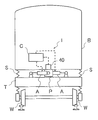
- FIG. 1 is a cross-sectional view of a railway vehicle equipped with a railway vehicle damping device according to an embodiment.
- FIG. 2 is a detailed view of the actuator.
- FIG. 3 is a control block diagram of a controller in the railcar vibration damping device of one embodiment.
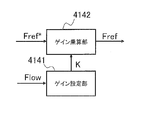
- FIG. 4 is a control block diagram of a correction unit in the railcar damping device of the first embodiment.
- FIG. 5 is a diagram for explaining a change in the value of the correction gain.
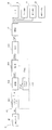
- FIG. 6 is a flowchart showing a processing procedure in the controller of the first embodiment.
- a railcar vibration damping device 1 is used as a vibration damping device for a vehicle body B of a railcar, and an actuator interposed as a pair between the vehicle body B and a carriage T as shown in FIG. A and a controller C that controls the actuator A are configured.
- the actuator A is connected to a pin P suspended below the vehicle body B, and is interposed between the vehicle body B and the carriage T in parallel.
- the carriage T rotatably holds the wheels W, and springs S and S are interposed between the vehicle body B and the carriage T, and the vehicle body B is elastically supported. Is allowed to move laterally.
- actuators A are basically actively controlled to suppress vibrations in the horizontal and lateral directions with respect to the vehicle traveling direction of the vehicle body B.
- the controller C controls the actuator A to suppress lateral vibration of the vehicle body B.
- the controller C detects the lateral acceleration ⁇ in the lateral direction with respect to the vehicle traveling direction of the vehicle body B when performing control to suppress the vibration of the vehicle body B. Then, the controller C obtains a target control force Fref to be generated by the actuator A based on the lateral acceleration ⁇ , and generates a thrust according to the target control force Fref to each actuator A to cause the lateral vibration of the vehicle body B. Suppress.
- Both of these actuators A have the same configuration. Although two actuators A are provided for the carriage T at the illustrated position, only one actuator A may be provided. One controller C may be provided for each actuator A.
- the actuator A includes a cylinder 2 connected to one of a vehicle body B and a carriage T of a railway vehicle, a piston 3 slidably inserted into the cylinder 2, A cylinder 3 having a piston 3, a rod 4 connected to the other of the vehicle body B and the carriage T, a rod side chamber 5 and a piston side chamber 6 partitioned by the piston 3 in the cylinder 2.
- the tank 7 that stores the hydraulic oil
- the pump 12 that can suck up the hydraulic oil from the tank 7 and supply the hydraulic oil to the rod side chamber 5, the motor 15 that drives the pump 12, and the expansion / contraction switching of the cylinder main body Cy.
- a hydraulic circuit HC that controls thrust, and is configured as a single rod type actuator.
- the rod side chamber 5 and the piston side chamber 6 are filled with working oil as working liquid
- the tank 7 is filled with gas in addition to working oil.
- other liquids may be used as the working liquid.
- the hydraulic circuit HC is provided in the middle of the first opening / closing valve 9 provided in the middle of the first passage 8 communicating the rod side chamber 5 and the piston side chamber 6 and the second passage 10 communicating the piston side chamber 6 and the tank 7. And a second on-off valve 11 provided.
- the cylinder 2 has a cylindrical shape, the right end in FIG. 2 is closed by a lid 13, and an annular rod guide 14 is attached to the left end in FIG.
- a rod 4 that is movably inserted into the cylinder 2 is slidably inserted into the rod guide 14.
- One end of the rod 4 protrudes outside the cylinder 2, and the other end in the cylinder 2 is connected to a piston 3 that is slidably inserted into the cylinder 2.
- the space between the outer periphery of the rod guide 14 and the cylinder 2 is sealed by a seal member (not shown), whereby the inside of the cylinder 2 is maintained in a sealed state.
- the rod-side chamber 5 and the piston-side chamber 6 partitioned by the piston 3 in the cylinder 2 are filled with hydraulic oil as described above.
- the cross-sectional area of the rod 4 is made half of the cross-sectional area of the piston 3, and the pressure receiving area on the rod side chamber 5 side of the piston 3 is half of the pressure receiving area on the piston side chamber 6 side. It is supposed to be. Therefore, if the pressure in the rod side chamber 5 is the same during the expansion operation and during the contraction operation, the thrust generated in both expansion and contraction becomes equal, and the amount of hydraulic oil relative to the displacement amount of the cylinder body Cy is the same on both expansion and contraction sides.
- the actuator A when the cylinder body Cy is extended, the rod side chamber 5 and the piston side chamber 6 are in communication with each other. Then, the pressures in the rod side chamber 5 and the piston side chamber 6 become equal, and the actuator A generates a thrust obtained by multiplying the pressure receiving area difference between the rod side chamber 5 side and the piston side chamber 6 side in the piston 3 by the pressure.
- the actuator A when the cylinder body Cy is contracted, the rod side chamber 5 and the piston side chamber 6 are disconnected from each other, and the piston side chamber 6 is connected to the tank 7. Then, the actuator A generates a thrust obtained by multiplying the pressure in the rod side chamber 5 by the pressure receiving area of the piston 3 on the rod side chamber 5 side.
- the thrust generated by the actuator A is a value obtained by multiplying a half of the cross-sectional area of the piston 3 by the pressure in the rod side chamber 5 in both expansion and contraction. Therefore, when the thrust of the actuator A is controlled, the pressure in the rod side chamber 5 may be controlled for both the extension operation and the contraction operation. Further, in the actuator A of the present example, the pressure receiving area on the rod side chamber 5 side of the piston 3 is set to one half of the pressure receiving area on the piston side chamber 6 side. Since the pressure in the rod side chamber 5 is the same on the contraction side, the control is simplified. In addition, since the amount of hydraulic oil with respect to the amount of displacement is the same, there is an advantage that the responsiveness is the same on both sides of expansion and contraction.
- the lid 4 that closes the left end of the rod 4 in FIG. 2 and the right end of the cylinder 2 is provided with a mounting portion (not shown), and this actuator A is interposed between the vehicle body B and the carriage T in the railway vehicle. Can be disguised.
- the rod side chamber 5 and the piston side chamber 6 communicate with each other through a first passage 8, and a first opening / closing valve 9 is provided in the middle of the first passage 8.
- the first passage 8 communicates the rod side chamber 5 and the piston side chamber 6 outside the cylinder 2, but may be provided in the piston 3.
- the first on-off valve 9 is an electromagnetic on-off valve.
- the first on-off valve 9 is opened to connect the rod-side chamber 5 and the piston-side chamber 6, and the first on-off passage 8 is shut off to connect to the rod-side chamber 5. And a blocking position for disconnecting communication with the piston side chamber 6. And this 1st on-off valve 9 takes a communicating position at the time of electricity supply, and takes a cutoff position at the time of non-energization.
- the second on-off valve 11 is an electromagnetic on-off valve, which opens the second passage 10 to communicate the piston side chamber 6 and the tank 7, and shuts off the second passage 10 to connect the piston side chamber 6 and the tank. 7 and a shut-off position that cuts off communication with 7. And this 2nd on-off valve 11 takes a communicating position at the time of electricity supply, and takes a cutoff position at the time of non-energization.
- the pump 12 is driven by a motor 15 that is controlled by the controller C and rotates at a predetermined rotational speed, and is a pump that discharges hydraulic oil only in one direction.
- the discharge port of the pump 12 communicates with the rod side chamber 5 through the supply passage 16 and the suction port communicates with the tank 7.
- the pump 12 sucks hydraulic oil from the tank 7 and Hydraulic oil is supplied to the side chamber 5.
- the pump 12 only discharges the hydraulic oil in one direction and does not switch the rotation direction, so there is no problem that the discharge amount changes at the time of rotation switching, and an inexpensive gear pump or the like can be used. . Further, since the rotation direction of the pump 12 is always the same direction, even the motor 15 that is a drive source for driving the pump 12 does not require high responsiveness to rotation switching, and the motor 15 is also inexpensive. Can be used. A check valve 17 that prevents the backflow of hydraulic oil from the rod side chamber 5 to the pump 12 is provided in the supply passage 16.
- the hydraulic circuit HC of the present example includes a discharge passage 21 that connects the rod side chamber 5 and the tank 7, and a variable relief that can change the valve opening pressure provided in the middle of the discharge passage 21.
- a valve 22 is provided.
- variable relief valve 22 is a proportional electromagnetic relief valve, and the valve opening pressure can be adjusted according to the amount of current to be supplied. When the amount of current is maximized, the valve opening pressure is minimized and no current is supplied. The valve opening pressure is maximized.
- the pressure in the rod side chamber 5 can be adjusted to the valve opening pressure of the variable relief valve 22 when the cylinder body Cy is expanded and contracted, and the thrust of the actuator A Can be controlled by the amount of current supplied to the variable relief valve 22.
- sensors necessary for adjusting the thrust force of the actuator A are not necessary, and it is not necessary to highly control the motor 15 for adjusting the discharge flow rate of the pump 12. . Therefore, the railcar vibration damping device 1 is inexpensive, and a robust system can be constructed in terms of hardware and software.
- the actuator A can exhibit a damping force only in one of expansion and contraction. Therefore, for example, when the direction in which the damping force is exerted is the direction in which the vehicle body B is vibrated by the vibration of the bogie T of the railway vehicle, the actuator A is provided with a one-effect damper so that no damping force is generated in such a direction. And can function. Therefore, since this actuator A can easily realize semi-active control based on Karnop's Skyhook theory, it can also function as a semi-active damper.
- a proportional electromagnetic relief valve that proportionally changes the valve opening pressure with the amount of current applied to the variable relief valve 22 is used, the control of the valve opening pressure is simplified.
- any variable relief valve that can adjust the valve opening pressure is used. It is not limited to a proportional electromagnetic relief valve.
- the variable relief valve 22 has an excessive input in the expansion / contraction direction to the cylinder body Cy regardless of the open / closed state of the first open / close valve 9 and the second open / close valve 11, and the pressure in the rod side chamber 5 increases the open valve pressure. When it exceeds, the discharge passage 21 is opened. As described above, the variable relief valve 22 discharges the pressure in the rod side chamber 5 to the tank 7 when the pressure in the rod side chamber 5 becomes equal to or higher than the valve opening pressure, so that the pressure in the cylinder 2 is prevented from becoming excessive. To protect the entire system of the actuator A. Therefore, if the discharge passage 21 and the variable relief valve 22 are provided, the system can be protected.
- the hydraulic circuit HC in the actuator A of the present example only allows the flow of the hydraulic oil that flows only from the piston side chamber 6 toward the rod side chamber 5 and allows the flow of the hydraulic oil toward the piston side chamber 6 from the tank 7.
- a permissible suction passage 19 is provided. Therefore, in the actuator A of this example, when the cylinder main body Cy expands and contracts while the first on-off valve 9 and the second on-off valve 11 are closed, the hydraulic oil is pushed out from the cylinder 2. Since the variable relief valve 22 provides resistance to the flow of hydraulic oil discharged from the cylinder 2, the actuator A of this example is a uniflow type in a state where the first on-off valve 9 and the second on-off valve 11 are closed. Functions as a damper.
- the rectifying passage 18 communicates the piston side chamber 6 and the rod side chamber 5, and a check valve 18 a is provided in the middle, allowing only the flow of hydraulic oil from the piston side chamber 6 toward the rod side chamber 5. It is set as a one-way passage. Further, the suction passage 19 communicates between the tank 7 and the piston side chamber 6, and a check valve 19 a is provided in the middle to allow only the flow of hydraulic oil from the tank 7 toward the piston side chamber 6. Is set to The rectifying passage 18 can be integrated into the first passage 8 when the shut-off position of the first on-off valve 9 is a check valve, and the suction passage 19 is also the first when the shut-off position of the second on-off valve 11 is a check valve. It can be concentrated in two passages 10.
- the actuator A configured as described above, even if the first on-off valve 9 and the second on-off valve 11 are both in the shut-off position, the rod side chamber 5, the piston side chamber 6 in the rectifying passage 18, the suction passage 19, and the discharge passage 21. And the tank 7 is made to communicate with a rosary chain.
- the rectifying passage 18, the suction passage 19, and the discharge passage 21 are set as one-way passages. Therefore, when the cylinder body Cy expands and contracts due to an external force, the hydraulic oil is surely discharged from the cylinder 2 and returned to the tank 7 through the discharge passage 21, and the hydraulic oil that is insufficient in the cylinder 2 passes from the tank 7 through the suction passage 19. Supplied into the cylinder 2. Since the variable relief valve 22 acts as a resistance against the flow of hydraulic oil and adjusts the pressure in the cylinder 2 to the valve opening pressure, the actuator A functions as a passive uniflow type damper.
- each of the first on-off valve 9 and the second on-off valve 11 takes the shut-off position, and the variable relief valve 22 has the maximum valve opening pressure. Functions as a fixed pressure control valve. Therefore, during such a failure, the actuator A automatically functions as a passive damper.
- the controller C basically rotates the motor 15 to supply the hydraulic oil from the pump 12 into the cylinder 2 while the first on-off valve. 9 is a communication position, and the second on-off valve 11 is a shut-off position. In this way, the rod side chamber 5 and the piston side chamber 6 are in communication with each other, and hydraulic oil is supplied to both of them from the pump 12, the piston 3 is pushed to the left in FIG. 2, and the actuator A generates thrust in the extension direction. Demonstrate.
- variable relief valve 22 When the pressure in the rod side chamber 5 and the piston side chamber 6 exceeds the valve opening pressure of the variable relief valve 22, the variable relief valve 22 is opened and the hydraulic oil is discharged to the tank 7 through the discharge passage 21. Therefore, the pressure in the rod side chamber 5 and the piston side chamber 6 is controlled by the valve opening pressure of the variable relief valve 22 determined by the amount of current applied to the variable relief valve 22.
- the actuator A then extends in the direction of extension of the value obtained by multiplying the pressure receiving area difference between the piston side chamber 6 side and the rod side chamber 5 side of the piston 3 by the pressure in the rod side chamber 5 and the piston side chamber 6 controlled by the variable relief valve 22. Demonstrate thrust.
- the controller C rotates the motor 15 to supply the hydraulic oil from the pump 12 into the rod side chamber 5 while turning the first on-off valve 9.
- the shut-off position is set, and the second on-off valve 11 is set to the communication position.
- the piston side chamber 6 and the tank 7 are brought into communication with each other and the hydraulic oil is supplied to the rod side chamber 5 from the pump 12, so that the piston 3 is pushed rightward in FIG. Demonstrate thrust.
- the actuator A multiplies the pressure receiving area of the piston 3 on the rod side chamber 5 side and the pressure in the rod side chamber 5 controlled by the variable relief valve 22. Demonstrate thrust in the contraction direction.
- the upper limit of the pressure in the rod side chamber 5 is limited to the discharge pressure of the pump 12 driven by the motor 15. That is, when the actuator A does not expand / contract with an external force but instead expands / contracts itself, the upper limit of the pressure in the rod side chamber 5 is limited to the maximum torque that the motor 15 can output.
- the actuator A not only functions as an actuator, but can function as a damper only by opening and closing the first on-off valve 9 and the second on-off valve 11 regardless of the driving state of the motor 15. Further, when switching the actuator A from the actuator to the damper, there is no troublesome and steep switching operation of the first on-off valve 9 and the second on-off valve 11, so that a system with high responsiveness and reliability can be provided.
- the actuator A of this example is set to a single rod type, it is easier to secure a stroke length than the double rod type actuator, and the total length of the actuator is shortened. Mountability is improved.
- the flow of hydraulic oil by the hydraulic oil supply from the pump 12 and the expansion / contraction operation in the actuator A of this example passes through the rod side chamber 5 and the piston side chamber 6 in order and finally returns to the tank 7. .
- the cylinder body Cy is automatically discharged to the tank 7 by the expansion / contraction operation. Therefore, when manufacturing the actuator A, it is not necessary to assemble in troublesome oil or in a vacuum environment, and advanced degassing of hydraulic oil is not required, improving productivity and reducing manufacturing cost. it can.
- the controller C includes an acceleration sensor 40 that detects the lateral acceleration ⁇ of the vehicle body B, a target control force calculation unit 41 that calculates a target control force Fref to be output by the actuator A, a target The motor 15, the first on-off valve 9, the second on-off valve 11, and the drive unit 42 that drives the variable relief valve 22 are provided based on the control force Fref.
- the acceleration sensor 40 detects the lateral acceleration ⁇ as a positive value when the direction is toward the right side in FIG. 1, and takes a negative value when the direction is toward the left side in FIG. Detect.
- the target control force calculation unit 41 includes a bandpass filter 411 that filters the lateral acceleration ⁇ , and a controller 412 that calculates a target control force Fref * that suppresses vibration of the vehicle body B from the lateral acceleration ⁇ .
- a correction unit 414 outputs a final target control force Fref the target control force Fref * that controller 412 has determined the correction to the limiter 415.
- the bandpass filter 411 filters the lateral acceleration ⁇ , removes the steady acceleration, drift component, and noise when the railway vehicle travels in a curved section from the lateral acceleration ⁇ , and inputs the filtered acceleration to the controller 412.
- the frequency band transmitted by the bandpass filter 411 is, for example, about 0.5 Hz to about 3 Hz so that an acceleration component of 0.7 Hz to 2 Hz, which is the resonance frequency band of the vehicle body B, can be sufficiently extracted while removing steady acceleration.
- the controller 412 is an H ⁇ controller, and calculates a target control force Fref * for suppressing the lateral vibration of the vehicle body B from the resonance frequency band component of the lateral acceleration ⁇ extracted by the bandpass filter 411. .
- the component in the resonance frequency band of the lateral acceleration ⁇ extracted by the bandpass filter 411 is the vibration acceleration in the resonance frequency band in the lateral direction of the vehicle body B. Therefore, the target control force Fref * before correction obtained by the controller 412 is optimal for suppressing the lateral vibration of the vehicle body B.
- the band pass filter 413 extracts only a frequency band in a range higher than 0.3 Hz that is a frequency band of steady acceleration and lower than 1 Hz of a resonance frequency band of the vehicle body B. That is, the band pass filter 413 extracts the low frequency control force Flow that is a component in the frequency band from 0.3 Hz to 1 Hz included in the target control force Fref * before correction.
- the correction unit 414 has a gain setting unit 4141 that sets the value of the correction gain K based on the low frequency control force Flow obtained by filtering the target control force Fref * with the bandpass filter 413, A gain multiplication unit 4142 for multiplying the target control force Fref * before correction by a correction gain K to obtain a final target control force Fref is provided.
- the gain setting unit 4141 compares the low frequency control force Flow output from the band pass filter 413 with the threshold value Ft. Then, the gain setting unit 4141 decreases the value of the correction gain K when the low frequency control force Flow is equal to or greater than the threshold Ft, and increases the value of the correction gain K when the low frequency control force Flow is less than the threshold Ft.
- the correction gain K increases or decreases on the basis of the above-mentioned reference, with the upper limit value being 1 and the lower limit value being 0.01. Specifically, when the low frequency control force Flow is equal to or greater than the threshold value Ft, the gain setting unit 4141 counts the time that satisfies this condition, and the value of the correction gain K during the time that the condition is satisfied.
- the gain setting unit 4141 counts the time that satisfies this condition, and gradually increases the value of the correction gain K during the time that the condition is satisfied. increase.
- the time required for the correction gain K value to increase from the lower limit value 0.01 to the upper limit value 1 is the same as the time required to decrease the correction gain K value. That is, if the calculation cycle of the target control force Fref is t seconds, the increase amount of the correction gain K with respect to the calculation cycle t is set to the same value as the decrease amount ⁇ .
- the time T required for the maximum decrease and increase of the correction gain K may be tuned so as to be optimal for the railway vehicle. For example, the period of the centrifugal acceleration during traveling in the relaxation curve section is reduced from 1/4 to 1 / It is set to about 2.
- the time gradually increases.
- the value of the correction gain K decreases from 1 and decreases to 0.01 in proportion to.
- the value of the correction gain K becomes 0.01, even if the condition that the low frequency control force Flow subsequently becomes equal to or greater than the threshold value Ft is satisfied, the value does not decrease any further.
- the correction gain K becomes 0.01, when the condition that the low frequency control force Flow is less than the threshold value Ft is continuously fulfilled and the time T elapses, the correction gain is gradually proportional to the time.
- the value of K increases from 0.01 and increases to 1.
- the value of the correction gain K becomes 1, even if the condition that the low frequency control force Flow subsequently becomes less than the threshold value Ft is satisfied, the value does not increase any more. Therefore, for example, if the condition that the value of the correction gain K is 1 and the condition that the low frequency control force Flow becomes equal to or greater than the threshold value Ft is continuously fulfilled for the time T1 (where 0 ⁇ T1 ⁇ T), the correction gain K The value of is 1 ⁇ ⁇ (T1 / t). Thereafter, when the condition that the low-frequency control force Flow is less than the threshold value Ft is continuously achieved for the time T1 or more, the value of the correction gain K gradually increases with the passage of time as shown by the broken line in FIG. 1
- the upper limit value Flim is set to such a value that the motor 15 is not excessively loaded even when the actuator A continuously exerts the force of the upper limit value Flim.
- the gain multiplication unit 4142 multiplies the target control force Fref * before correction by the correction gain K set by the gain setting unit 4141 to obtain the final target control force Fref and outputs it to the drive unit 42. Therefore, when the low frequency control force Flow becomes equal to or greater than the threshold value Ft, the correction gain K decreases, so that the chance of reaching the upper limit value Flim in the final target control force Fref after correction is reduced.
- the drive unit 42 includes a driver circuit that drives the motor 15, the first on-off valve 9, the second on-off valve 11, and the variable relief valve 22.
- the drive unit 43 controls the amount of current supplied to the motor 15, the first on-off valve 9, the second on-off valve 11, and the variable relief valve 22 in the actuator A according to the control force F, and according to the target control force Fref. Actuator A exerts thrust.
- the controller C is not illustrated, but specifically, for example, an A / D converter for capturing a signal output from the acceleration sensor 40, and an actuator A by capturing a lateral acceleration ⁇ .
- a storage device such as a ROM (Read Only Memory) in which a program used for processing necessary for control is stored, a calculation device such as a CPU (Central Processing Unit) that executes processing based on the program, and the above It may be configured to include a storage device such as a RAM (Random Access Memory) that provides a storage area to the CPU.
- a RAM Random Access Memory
- the controller C takes in the lateral acceleration ⁇ (step F1). Subsequently, the controller C obtains the target control force Fref * from the lateral acceleration ⁇ (step F2). Next, the controller C performs a band pass filter process on the target control force Fref * to obtain a low frequency control force Flow (step F3). Further, the controller C compares the low frequency control force Flow with the threshold value Ft, and determines whether or not Flow ⁇ Ft (step F4). Then, the controller C decreases the value of the correction gain K when Flow ⁇ Ft (step F5).
- step F6 the controller C increases the value of the correction gain K (step F6). Further, the controller C obtains the final target control force Fref by multiplying the target control force Fref * by the correction gain K (step F7). Finally, the controller C drives the motor 15 of the actuator A, the first on-off valve 9, the second on-off valve 11 and the variable relief valve 22 based on the control force F to cause the actuator A to exert thrust (step F8). ).
- the railcar vibration damping device 1 is based on the actuator A that is interposed between the vehicle body B and the carriage T of the railcar and can exert the control force, and the lateral acceleration ⁇ of the vehicle body B.
- a bandpass filter 413 that extracts a low-frequency control force Flow that is a frequency component lower than the resonance frequency of the vehicle body B, and a controller C that obtains a target control force Fref that suppresses B vibration.
- a correction unit 414 that corrects the target control force Fref * based on the force Flow.
- the railcar damping device 1 of the present invention can extract a force component for countering the centrifugal acceleration acting on the vehicle body B traveling in the relaxation curve section from the target control force Fref * with the bandpass filter 413. .
- the target control force Fref * is corrected based on the low-frequency control force Flow extracted by the bandpass filter 413, the final target control force is influenced by the centrifugal acceleration during traveling in the relaxation curve section that cannot be removed by the bandpass filter 411. It can suppress that Fref becomes excessive.
- the correction unit 414 corrects the target control force Fref * based on the low frequency control force Flow, but the target control force Fref * also includes a component that suppresses vibration of the vehicle body B transmitted from the cart T side. ing. Therefore, if the corrected target control force Fref is kept below the upper limit value Flim by the limiter 415, the force exerted by the actuator A is reduced, but the force component that suppresses the vibration of the vehicle body B is not lost. Ride comfort is improved. Further, since the target control force Fref * is corrected to prevent the final target control force Fref from becoming excessive, it is not necessary to use a large motor.
- the railcar vibration damping device 1 of the present invention since a large motor is not required, the cost and ease of mounting on the railcar are not impaired, and the riding comfort during traveling in the relaxation curve section can be improved. is there.
- the bandpass filter 413 extracts a frequency component that is higher than the steady acceleration frequency band of the target control force Fref * and lower than the resonance frequency of the vehicle body B, but is lower than the resonance frequency of the vehicle body B. It is also possible to use a low-pass filter that allows transmission of frequency components. Even when the low-pass filter is used in this way, the target control force Fref * is obtained from the lateral acceleration ⁇ from which the steady acceleration component has been removed by the band-pass filter 411. Accordingly, since the target control force Fref * does not increase due to the influence of the steady acceleration, there is no disadvantage because the target control force Fref is not corrected to be small when traveling in a curved section.
- the correction unit 414 corrects the target control force Fref so that the target control force Fref is reduced when the low frequency control force Flow is equal to or greater than the threshold value Ft.
- the opportunity to be limited by the limiter 415 can be reduced, and a high riding comfort improvement effect can be exhibited.
- the correction unit 414 multiplies the target control force Fref * by the correction gain K having an upper limit value of 1 or less.
- the control force Fref * is corrected.
- the frequency of the target control force Fref * before correction and the frequency of the target control force Fref after correction do not change, so that the vehicle body B transmitted from the cart T side further.
- the effect of suppressing the vibration of is increased. Therefore, according to the railway vehicle vibration damping device 1 configured as described above, it is possible to further improve the riding comfort during traveling in the relaxation curve section.
- the correction unit 414 gradually decreases the correction gain K while the low frequency control force Flow is equal to or greater than the threshold value Ft, and the low frequency control force Flow is set to the threshold value Ft. If it is less than the value, the correction gain K is increased. That is, in the railway vehicle vibration damping device 1 of the present example, as described above, the correction gain K is decreased according to the time when the target control force Fref * is equal to or greater than the threshold value Ft, and according to the time when the target control force Fref * is less than the threshold value Ft. Increase.
- the sudden change in the value of the correction gain K is mitigated, the sudden change in the corrected target control force Fref is also mitigated, so that the riding comfort is further improved. .
- the correction unit 414 is a correction gain K target control force Fref * is reduced according to the time equal to or larger than the threshold value Ft, the target control force Fref * exceeds the upper limit value Flim
- the value of the correction gain K may be changed according to the amount. That is, the value of the correction gain K may be decreased as the amount of the target control force Fref * exceeding the upper limit value Flim increases.
- the correction unit 414 multiplies the correction gain K to correct the target control force Fref * . If the target control force Fref * is a positive value, the correction unit 414 is constant from the target control force Fref *. If the value is subtracted and the target control force Fref * is a negative value, the target control force Fref * may be corrected by adding a constant value. Also in this case, the frequency of the target control force Fref does not change before and after the correction.
Landscapes
- Engineering & Computer Science (AREA)
- Mechanical Engineering (AREA)
- General Engineering & Computer Science (AREA)
- Physics & Mathematics (AREA)
- Acoustics & Sound (AREA)
- Aviation & Aerospace Engineering (AREA)
- Chemical & Material Sciences (AREA)
- Analytical Chemistry (AREA)
- Fluid Mechanics (AREA)
- Vehicle Body Suspensions (AREA)
- Fluid-Pressure Circuits (AREA)
Abstract
本発明の鉄道車両用制振装置(1)は、鉄道車両の車体(B)と台車(T)との間に介装されて制御力を発揮可能なアクチュエータ(A)と、車体(B)の横方向加速度(α)に基づいて車体(B)の振動を抑制する目標制御力(Fref)を求めるコントローラ(C)とを備え、コントローラ(C)が車体Bの共振周波数よりも低い周波数成分である低周波制御力(Flow)を抽出するバンドパスフィルタ(413)と、低周波制御力(Flow)に基づいて目標制御力(Fref*)を補正する補正部(414)とを有して構成される。
Description
本発明は、鉄道車両用制振装置の改良に関する。
鉄道車両には、車体と台車との間に介装された複動型のアクチュエータと、アクチュエータを制御するコントローラを備えて、車体の進行方向に対して左右方向の振動を抑制する鉄道車両用制振装置が設けられている。そして、鉄道車両用制振装置は、加速度センサで検知した車体の左右方向の加速度をコントローラに入力して、加速度フィードバックによりアクチュエータを制御し、車体の左右動を抑制できる。
ところで、鉄道車両が曲線区間を走行する場合、車体には定常加速度と称される遠心加速度が作用するため、加速度センサが検知する加速度には、台車側から入力されて車体を横方向へ振動させる加速度の他に定常加速度が含まれる。
乗心地を悪化させる主因は、車体の横方向の振動にあって、定常加速度に対抗する力をアクチュエータに発揮させようとするとアクチュエータが過大な力を発揮せざるを得ず、アクチュエータの駆動源であるポンプを駆動するモータに過負荷がかかってしまう。そこで、鉄道車両用制振装置では、たとえば、JP2012-245926Aに開示されているように、加速度センサが検知する加速度から定常加速度を取り除く処理を行ってから加速度フィードバックによってアクチュエータを制御し、前記振動を抑制して乗心地の向上を図っている。
定常加速度の周波数帯は、0.3Hz程度であり、一般的に車体の共振周波数帯は、1Hzから1.5Hz程度であって、両者の周波数帯は非常に接近している。定常加速度を取り除くバンドパスフィルタの下側のカットオフ周波数は、低すぎると定常加速度の除去が不十分となり、高すぎると抑制したい振動成分まで除去してしまい制振効果が低下する。よって、前記バンドパスフィルタのカットオフ周波数は、定常加速度の周波数帯と車体の共振周波数帯の間の極限られた範囲に設定する他はない。
ここで、鉄道車両が直線区間から直線区間と定常曲線区間の間に設置される緩和曲線区間に差しかかると車体には遠心加速度が作用する。この遠心加速度に起因する振動の周波数帯は、定常曲線区間走行時における定常加速度の周波数帯よりも高いが車体の共振周波数帯よりも低い。
前述のようなフィルタのカットオフ周波数の設定では、緩和曲線区間走行時の遠心加速度を取り除けないため、従来の鉄道車両用制振装置では、アクチュエータにこの遠心加速度を抑制する制御力を発生させる制御を行う。
前述したように、遠心加速度に対抗して車体を押す力は非常に大きいため、アクチュエータに大きな力を発揮させなくてはならず、従来の鉄道車両用制振装置では、モータの過負荷を避けるためにリミッタを設けていて、制御力を制限する。このように制御力が制限されてしまうと、本来、抑制したい台車から入力される車体の振動を抑制できなくなって、車両における乗心地を損なってしまう。
また、アクチュエータの制御力の上限を大きくするには、モータの大型化すればよいが、鉄道車両用制振装置のコストが嵩むとともに鉄道車両への搭載性が損なってしまう。
本発明の目的は、コストと鉄道車両への搭載性を損なわずに緩和曲線区間走行時の乗心地を向上できる鉄道車両用制振装置の提供である。
本発明の鉄道車両用制振装置は、鉄道車両の車体と台車との間に介装されて制御力を発揮可能なアクチュエータと、前記車体の横方向加速度に基づいて前記車体の振動を抑制する目標制御力を求めて前記アクチュエータを制御するコントローラとを備え、前記コントローラは、前記目標制御力における前記車体の共振周波数よりも低い周波数成分である低周波制御力を抽出するフィルタと、前記低周波制御力に基づいて前記目標制御力を補正する補正部とを有する。
以下、図に示した実施の形態に基づき、本発明を説明する。一実施の形態における鉄道車両用制振装置1は、鉄道車両の車体Bの制振装置として使用され、図1に示すように、車体Bと台車Tとの間に対として介装されるアクチュエータAと、アクチュエータAを制御するコントローラCとを備えて構成されている。
アクチュエータAは、詳細には、鉄道車両の場合、車体Bの下方に垂下されるピンPに連結され、車体Bと台車Tとの間で対を成して並列に介装されている。台車Tは、車輪Wを回転自在に保持しており、車体Bと台車Tとの間には、ばねS,Sが介装され、車体Bが弾性支持されることにより、台車Tに対する車体Bの横方向への移動が許容されている。
そして、これらのアクチュエータAは、基本的には、アクティブ制御されて、車体Bの車両進行方向に対して水平横方向の振動を抑制するようになっている。コントローラCは、アクチュエータAを制御して前記車体Bの横方向の振動を抑制するようになっている。
コントローラCは、本例にあっては、車体Bの振動を抑制する制御を行う際に、車体Bの車両進行方向に対して水平横方向の横方向加速度αを検知する。そして、コントローラCは、横方向加速度αに基づいて、アクチュエータAが発生すべき目標制御力Frefを求め、各アクチュエータAに目標制御力Fref通りの推力を発生させて車体Bの前記横方向の振動を抑制する。
つづいて、アクチュエータAの具体的な構成について説明する。これらアクチュエータAは、共に同じ構成である。なお、図示したところでは、アクチュエータAが台車Tに対して二つずつ設けられているが、一つのみを設けてもよい。また、各アクチュエータAに対して一つずつコントローラCを設けてもよい。
アクチュエータAは、本例では図2に示すように、鉄道車両の車体Bと台車Tの一方に連結されるシリンダ2と、シリンダ2内に摺動自在に挿入されるピストン3と、シリンダ2内に挿入されてピストン3と、車体Bと台車Tの他方に連結されるロッド4と、シリンダ2内にピストン3で区画したロッド側室5とピストン側室6とを備えて伸縮可能なシリンダ本体Cyに加え、作動油を貯留するタンク7と、タンク7から作動油を吸い上げてロッド側室5へ作動油を供給可能なポンプ12と、ポンプ12を駆動するモータ15と、シリンダ本体Cyの伸縮の切換と推力を制御する液圧回路HCとを備えており、片ロッド型のアクチュエータとして構成されている。
また、前記ロッド側室5とピストン側室6には、本例では、作動液体として作動油が充填されるとともに、タンク7には、作動油のほかに気体が充填されている。なお、タンク7内は、特に、気体を圧縮して充填して加圧状態とする必要は無い。また、作動液体は、作動油以外にも他の液体を利用してもよい。
液圧回路HCは、ロッド側室5とピストン側室6とを連通する第一通路8の途中に設けた第一開閉弁9と、ピストン側室6とタンク7とを連通する第二通路10の途中に設けた第二開閉弁11とを備えている。
そして、基本的には、第一開閉弁9で第一通路8を連通状態とし、第二開閉弁11を閉じてポンプ12を駆動すると、シリンダ本体Cyが伸長し、第二開閉弁11で第二通路10を連通状態とし、第一開閉弁9を閉じてポンプ12を駆動すると、シリンダ本体Cyが収縮する。
以下、アクチュエータAの各部について詳細に説明する。シリンダ2は筒状であって、その図2中右端は蓋13によって閉塞され、図2中左端には環状のロッドガイド14が取り付けられている。また、前記ロッドガイド14内には、シリンダ2内に移動自在に挿入されるロッド4が摺動自在に挿入されている。このロッド4は、一端をシリンダ2外へ突出させており、シリンダ2内の他端をシリンダ2内に摺動自在に挿入されるピストン3に連結している。
なお、ロッドガイド14の外周とシリンダ2との間は図示を省略したシール部材によってシールされており、これによりシリンダ2内は密閉状態に維持されている。そして、シリンダ2内にピストン3によって区画されるロッド側室5とピストン側室6には、前述のように作動油が充填されている。
また、このシリンダ本体Cyの場合、ロッド4の断面積をピストン3の断面積の二分の一にして、ピストン3のロッド側室5側の受圧面積がピストン側室6側の受圧面積の二分の一となるようになっている。よって、伸長作動時と収縮作動時とでロッド側室5の圧力を同じくすると、伸縮の双方で発生される推力が等しくなり、シリンダ本体Cyの変位量に対する作動油量も伸縮両側で同じとなる。
詳しくは、シリンダ本体Cyを伸長作動させる場合、ロッド側室5とピストン側室6を連通させた状態とする。すると、ロッド側室5内とピストン側室6内の圧力が等しくなり、アクチュエータAは、ピストン3におけるロッド側室5側とピストン側室6側の受圧面積差に前記圧力を乗じた推力を発生する。反対に、シリンダ本体Cyを収縮作動させる場合、ロッド側室5とピストン側室6との連通を断ちピストン側室6をタンク7に連通させた状態とする。すると、アクチュエータAは、ロッド側室5内の圧力とピストン3におけるロッド側室5側の受圧面積を乗じた推力を発生する。
要するに、アクチュエータAの発生推力は伸縮の双方でピストン3の断面積の二分の一にロッド側室5の圧力を乗じた値となるのである。したがって、このアクチュエータAの推力を制御する場合、伸長作動、収縮作動共に、ロッド側室5の圧力を制御すればよい。また、本例のアクチュエータAでは、ピストン3のロッド側室5側の受圧面積をピストン側室6側の受圧面積の二分の一に設定しているので、伸縮両側で同じ推力を発生する場合に伸長側と収縮側でロッド側室5の圧力が同じとなるので制御が簡素となる。加えて、変位量に対する作動油量も同じとなるので伸縮両側で応答性が同じとなる利点がある。なお、ピストン3のロッド側室5側の受圧面積をピストン側室6側の受圧面積の二分の一に設定しない場合にあっても、ロッド側室5の圧力でアクチュエータAの伸縮両側の推力を制御できる点は変わらない。
戻って、ロッド4の図2中左端とシリンダ2の右端を閉塞する蓋13とには、図示しない取付部を備えており、このアクチュエータAを鉄道車両における車体Bと台車Tとの間に介装できるようになっている。
そして、ロッド側室5とピストン側室6とは、第一通路8によって連通されており、この第一通路8の途中には、第一開閉弁9が設けられている。この第一通路8は、シリンダ2外でロッド側室5とピストン側室6とを連通しているが、ピストン3に設けられてもよい。
第一開閉弁9は、電磁開閉弁とされており、第一通路8を開放してロッド側室5とピストン側室6とを連通する連通ポジションと、第一通路8を遮断してロッド側室5とピストン側室6との連通を断つ遮断ポジションとを備えている。そして、この第一開閉弁9は、通電時に連通ポジションを採り、非通電時に遮断ポジションを採るようになっている。
つづいて、ピストン側室6とタンク7とは、第二通路10によって連通されており、この第二通路10の途中には、第二開閉弁11が設けられている。第二開閉弁11は、電磁開閉弁とされており、第二通路10を開放してピストン側室6とタンク7とを連通する連通ポジションと、第二通路10を遮断してピストン側室6とタンク7との連通を断つ遮断ポジションとを備えている。そして、この第二開閉弁11は、通電時に連通ポジションを採り、非通電時に遮断ポジションを採るようになっている。
ポンプ12は、コントローラCに制御されて所定の回転数で回転するモータ15によって駆動され、一方向のみに作動油を吐出するポンプとされている。そして、ポンプ12の吐出口は供給通路16によってロッド側室5へ連通されるとともに吸込口はタンク7に通じていて、ポンプ12は、モータ15によって駆動されるとタンク7から作動油を吸込んでロッド側室5へ作動油を供給する。
前述のようにポンプ12は、一方向のみに作動油を吐出するのみで回転方向の切換動作がないので、回転切換時に吐出量が変化するといった問題は皆無であり、安価なギアポンプ等を使用できる。さらに、ポンプ12の回転方向が常に同一方向であるので、ポンプ12を駆動する駆動源であるモータ15にあっても回転切換に対する高い応答性が要求されず、その分、モータ15も安価なものを使用できる。なお、供給通路16の途中には、ロッド側室5からポンプ12への作動油の逆流を阻止する逆止弁17が設けられている。
さらに、本例の液圧回路HCは、前述の構成に加えて、ロッド側室5とタンク7とを接続する排出通路21と、排出通路21の途中に設けた開弁圧を変更可能な可変リリーフ弁22を備えている。
可変リリーフ弁22は、本例では、比例電磁リリーフ弁とされており、供給する電流量に応じて開弁圧を調節でき、電流量を最大とすると開弁圧を最小とし、電流を供給しないと開弁圧を最大とするようになっている。
このように、排出通路21と可変リリーフ弁22とを設けると、シリンダ本体Cyを伸縮作動させる際に、ロッド側室5内の圧力を可変リリーフ弁22の開弁圧に調節でき、アクチュエータAの推力を可変リリーフ弁22へ供給する電流量で制御できる。排出通路21と可変リリーフ弁22とを設けると、アクチュエータAの推力を調節するために必要なセンサ類が不要となり、ポンプ12の吐出流量の調節のためにモータ15を高度に制御する必要もなくなる。よって、鉄道車両用制振装置1が安価となり、ハードウェア的にもソフトウェア的にも堅牢なシステムを構築できる。
なお、第一開閉弁9を開いて第二開閉弁11を閉じる場合或いは第一開閉弁9を閉じて第二開閉弁11を開く場合、ポンプ12の駆動状況に関わらず、外力からの振動入力に対して伸長或いは収縮のいずれか一方にのみアクチュエータAが減衰力を発揮できる。よって、たとえば、減衰力を発揮する方向が鉄道車両の台車Tの振動により車体Bを加振する方向である場合、そのような方向には減衰力を出さないようにアクチュエータAを片効きのダンパと機能させ得る。よって、このアクチュエータAは、カルノップのスカイフック理論に基づくセミアクティブ制御を容易に実現できるため、セミアクティブダンパとしても機能できる。
なお、可変リリーフ弁22に与える電流量で開弁圧を比例的に変化させる比例電磁リリーフ弁を用いると開弁圧の制御が簡単となるが、開弁圧を調節できる可変リリーフ弁であれば比例電磁リリーフ弁に限定されない。
そして、可変リリーフ弁22は、第一開閉弁9および第二開閉弁11の開閉状態に関わらず、シリンダ本体Cyに伸縮方向の過大な入力があって、ロッド側室5の圧力が開弁圧を超える状態となると、排出通路21を開放する。このように、可変リリーフ弁22は、ロッド側室5の圧力が開弁圧以上となると、ロッド側室5内の圧力をタンク7へ排出するので、シリンダ2内の圧力が過大となるのを防止してアクチュエータAのシステム全体を保護する。よって、排出通路21と可変リリーフ弁22を設けると、システムの保護も可能となる。
さらに、本例のアクチュエータAにおける液圧回路HCは、ピストン側室6からロッド側室5へ向かう作動油の流れのみを許容する整流通路18と、タンク7からピストン側室6へ向かう作動油の流れのみを許容する吸込通路19を備えている。よって、本例のアクチュエータAでは、第一開閉弁9および第二開閉弁11が閉弁する状態でシリンダ本体Cyが伸縮すると、シリンダ2内から作動油が押し出される。シリンダ2内から排出された作動油の流れに対して可変リリーフ弁22が抵抗を与えるので、第一開閉弁9および第二開閉弁11が閉弁する状態では、本例のアクチュエータAはユニフロー型のダンパとして機能する。
より詳細には、整流通路18は、ピストン側室6とロッド側室5とを連通しており、途中に逆止弁18aが設けられ、ピストン側室6からロッド側室5へ向かう作動油の流れのみを許容する一方通行の通路に設定されている。さらに、吸込通路19は、タンク7とピストン側室6とを連通しており、途中に逆止弁19aが設けられ、タンク7からピストン側室6へ向かう作動油の流れのみを許容する一方通行の通路に設定されている。なお、整流通路18は、第一開閉弁9の遮断ポジションを逆止弁とすると第一通路8に集約でき、吸込通路19についても、第二開閉弁11の遮断ポジションを逆止弁とすると第二通路10に集約できる。
このように構成されたアクチュエータAでは、第一開閉弁9と第二開閉弁11がともに遮断ポジションを採っても、整流通路18、吸込通路19および排出通路21で、ロッド側室5、ピストン側室6およびタンク7を数珠繋ぎに連通させる。また、整流通路18、吸込通路19および排出通路21は、一方通行の通路に設定されている。よって、シリンダ本体Cyが外力によって伸縮すると、シリンダ2から必ず作動油が排出されて排出通路21を介してタンク7へ戻され、シリンダ2で足りなくなる作動油は吸込通路19を介してタンク7からシリンダ2内へ供給される。この作動油の流れに対して前記可変リリーフ弁22が抵抗となってシリンダ2内の圧力を開弁圧に調節するので、アクチュエータAは、パッシブなユニフロー型のダンパとして機能する。
また、アクチュエータAの各機器への通電が不能となるようなフェール時には、第一開閉弁9と第二開閉弁11のそれぞれが遮断ポジションを採り、可変リリーフ弁22は、開弁圧が最大に固定された圧力制御弁として機能する。よって、このようなフェール時には、アクチュエータAは、自動的に、パッシブダンパとして機能する。
つづいて、アクチュエータAに所望の伸長方向の推力を発揮させる場合、コントローラCは、基本的には、モータ15を回転させてポンプ12からシリンダ2内へ作動油を供給しつつ、第一開閉弁9を連通ポジションとし、第二開閉弁11を遮断ポジションとする。このようにすると、ロッド側室5とピストン側室6とが連通状態におかれて両者にポンプ12から作動油が供給され、ピストン3が図2中左方へ押されアクチュエータAは伸長方向の推力を発揮する。ロッド側室5内およびピストン側室6内の圧力が可変リリーフ弁22の開弁圧を上回ると、可変リリーフ弁22が開弁して作動油が排出通路21を介してタンク7へ排出される。よって、ロッド側室5内およびピストン側室6内の圧力は、可変リリーフ弁22に与える電流量で決まる可変リリーフ弁22の開弁圧にコントロールされる。そして、アクチュエータAは、ピストン3におけるピストン側室6側とロッド側室5側の受圧面積差に可変リリーフ弁22によってコントロールされるロッド側室5内およびピストン側室6内の圧力を乗じた値の伸長方向の推力を発揮する。
これに対して、アクチュエータAに所望の収縮方向の推力を発揮させる場合、コントローラCは、モータ15を回転させてポンプ12からロッド側室5内へ作動油を供給しつつ、第一開閉弁9を遮断ポジションとし、第二開閉弁11を連通ポジションとする。このようにすると、ピストン側室6とタンク7が連通状態におかれるとともにロッド側室5にポンプ12から作動油が供給されるので、ピストン3が図2中右方へ押されアクチュエータAは収縮方向の推力を発揮する。そして、前述と同様に、可変リリーフ弁22の電流量を調節すると、アクチュエータAは、ピストン3におけるロッド側室5側の受圧面積と可変リリーフ弁22によってコントロールされるロッド側室5内の圧力を乗じた収縮方向の推力を発揮する。
ここで、アクチュエータAが外力で伸縮するのではなく、自ら伸縮する場合、ロッド側室5の圧力の上限は、モータ15が駆動するポンプ12の吐出圧に制限される。つまり、アクチュエータAが外力で伸縮するのではなく、自ら伸縮する場合、ロッド側室5の圧力の上限は、モータ15が出力可能な最大トルクに制限される。
また、アクチュエータAにあっては、アクチュエータとして機能するのみならず、モータ15の駆動状況に関わらず、第一開閉弁9と第二開閉弁11の開閉のみでダンパとしても機能できる。また、アクチュエータAをアクチュエータからダンパへ切換える際に、面倒かつ急峻な第一開閉弁9と第二開閉弁11の切換動作を伴わないので、応答性および信頼性が高いシステムを提供できる。
なお、本例のアクチュエータAにあっては、片ロッド型に設定されているので、両ロッド型のアクチュエータに比較してストローク長を確保しやすく、アクチュエータの全長が短くなって、鉄道車両への搭載性が向上する。
また、本例のアクチュエータAにおけるポンプ12からの作動油供給および伸縮作動による作動油の流れは、ロッド側室5、ピストン側室6を順に通過して最終的にタンク7へ還流するようになっている。そのため、ロッド側室5あるいはピストン側室6内に気体が混入しても、シリンダ本体Cyの伸縮作動によって自立的にタンク7へ排出されるので、推力発生の応答性の悪化を阻止できる。したがって、アクチュエータAの製造にあたって、面倒な油中での組立や真空環境下での組立を強いられず、作動油の高度な脱気も不要となるので、生産性が向上するとともに製造コストを低減できる。さらに、ロッド側室5あるいはピストン側室6内に気体が混入しても、気体は、シリンダ本体Cyの伸縮作動によって自立的にタンク7へ排出されるので、性能回復のためのメンテナンスを頻繁に行う必要もなくなり、保守面における労力とコスト負担を軽減できる。
つづいて、コントローラCは、図3に示すように、車体Bの横方向加速度αを検知する加速度センサ40と、アクチュエータAが出力すべき目標制御力Frefを求める目標制御力演算部41と、目標制御力Frefに基づいてモータ15、第一開閉弁9、第二開閉弁11、可変リリーフ弁22を駆動する駆動部42とを備えている。
加速度センサ40は、図1中で右側へ向く方向となる場合に、横方向加速度αを正の値として検知し、反対に図1中左側へ向く方向となる場合に負の値とをして検知する。
目標制御力演算部41は、図3に示すように、横方向加速度αを濾波するバンドパスフィルタ411と、横方向加速度αから車体Bの振動を抑制する目標制御力Fref*を求める制御器412と、補正前の目標制御力Fref*を濾波するバンドパスフィルタ413と、制御器412が求めた目標制御力Fref*を補正して最終的な目標制御力Frefを出力する補正部414と、リミッタ415とを備えて構成されている。
バンドパスフィルタ411は、横方向加速度αを濾波して、横方向加速度αから鉄道車両が曲線区間を走行する際の定常加速度、ドリフト成分やノイズを除去して、制御器412へ入力する。バンドパスフィルタ411が透過する周波数帯は、定常加速度を除去しつつ車体Bの共振周波数帯である0.7Hzから2Hzの加速度成分を充分に抽出できるように、たとえば、0.5Hz程度から3Hz程度に設定される。このように、バンドパスフィルタ411で横方向加速度αに含まれる曲線走行時の定常加速度が除去されて制御器412に入力されるので、乗心地を悪化させる振動のみを抑制できる。
制御器412は、H∞制御器とされており、バンドパスフィルタ411が抽出した横方向加速度αの共振周波数帯の成分から車体Bの横方向の振動を抑制する目標制御力Fref*を演算する。バンドパスフィルタ411が抽出した横方向加速度αの共振周波数帯の成分は、車体Bの横方向の共振周波数帯の振動加速度である。したがって、制御器412が求める補正前の目標制御力Fref*は、車体Bの横方向の振動の抑制に最適となる。
バンドパスフィルタ413は、本例では、定常加速度の周波数帯である0.3Hzより大きく車体Bの共振周波数帯の1Hzよりも低い範囲の周波数帯のみを抽出する。つまり、バンドパスフィルタ413は、補正前の目標制御力Fref*に含まれる0.3Hzから1Hzまでの周波数帯の成分である低周波制御力Flowを抽出するようになっている。
補正部414は、図4に示すように、目標制御力Fref*をバンドパスフィルタ413で濾波して得た低周波制御力Flowに基づいて補正ゲインKの値を設定するゲイン設定部4141と、補正前の目標制御力Fref*に補正ゲインKを乗じて最終的な目標制御力Frefを求めるゲイン乗算部4142とを備えて構成されている。
ゲイン設定部4141は、バンドパスフィルタ413が出力した低周波制御力Flowと閾値Ftとを比較する。そして、ゲイン設定部4141は、低周波制御力Flowが閾値Ft以上であると、補正ゲインKの値を低下させ、低周波制御力Flowが閾値Ft未満であると、補正ゲインKの値を増加させる。補正ゲインKは、本例では、上限値を1、下限値を0.01として前述の基準で値が増減する。具体的には、ゲイン設定部4141は、低周波制御力Flowが閾値Ft以上であると、この条件を満たしている時間をカウントして、条件が成就している時間中は補正ゲインKの値を徐々に低下させる。詳細には、図5に示すように、補正ゲインKの値が上限値の1から下限値の0.01まで減少させるまでの時間Tを予め決めてある。つまり、目標制御力Frefの演算周期をt秒とすると、補正ゲインKの演算周期tに対する減少量βを予め決めてある。よって、ゲイン設定部4141は、前回の補正ゲインKの値をKpreとし、低周波制御力Flowが閾値Ft以上の条件が成就すると、今回の補正ゲインKの値は、K=Kpre-β×tを演算して求める。他方、ゲイン設定部4141は、低周波制御力Flowが閾値Ft未満であると、この条件を満たしている時間をカウントして、条件が成就している時間中は補正ゲインKの値を徐々に増加させる。なお、補正ゲインKの値が下限値の0.01から上限値の1まで上昇させるまでの時間は、減少させるまでに要する時間と同じにしてある。つまり、目標制御力Frefの演算周期をt秒とすると、補正ゲインKの演算周期tに対する増加量は減少量βと同じ値に設定してある。よって、ゲイン設定部4141は、前回の補正ゲインKの値をKpreとし、低周波制御力Flowが閾値Ft未満であると、今回の補正ゲインKの値は、K=Kpre+β×tを演算して求める。なお、補正ゲインKの最大限の低下および上昇に要する時間Tは、鉄道車両に最適となるようにチューニングすればよく、たとえば、緩和曲線区間走行時における遠心加速度の周期の1/4から1/2程度に設定される。
図5中の実線で示すように、補正ゲインKの値が1である状況から、低周波制御力Flowが閾値Ft以上となる条件が連続して成就して時間Tを経過すると、徐々に時間に比例して補正ゲインKの値が1から減少して0.01まで低下する。補正ゲインKの値が0.01となると、引き続いて低周波制御力Flowが閾値Ft以上となる条件が成就しても、これ以上値は低下しない。他方、補正ゲインKの値が0.01となった後、低周波制御力Flowが閾値Ft未満となる条件が連続して成就して時間Tを経過すると、徐々に時間に比例して補正ゲインKの値が0.01から増加して1まで上昇する。補正ゲインKの値が1となると、引き続いて低周波制御力Flowが閾値Ft未満となる条件が成就しても、これ以上値は上昇しない。よって、たとえば、補正ゲインKの値が1であった状況から低周波制御力Flowが閾値Ft以上となる条件が時間T1(ただし、0<T1<T)だけ連続して成就すると、補正ゲインKの値は、1-β×(T1/t)となる。その後、低周波制御力Flowが閾値Ft未満となる条件が時間T1以上連続して成就すると、図5中の破線で示すように、補正ゲインKの値は時間の経過にしたがって徐々に上昇して1となる。
なお、閾値Ftの値は、本例では、リミッタ415が制限する目標制御力Frefの上限値Flimの二分の1の値に設定されている。つまり、閾値Ft=Flim/2に設定されている。上限値Flimは、アクチュエータAが連続して上限値Flimの力を発揮しても、モータ15に過剰に負荷がかからない程度の値に設定されている。
ゲイン乗算部4142は、補正前の目標制御力Fref*にゲイン設定部4141で設定された補正ゲインKを乗じて最終的な目標制御力Frefを求めて駆動部42へ出力する。よって、低周波制御力Flowが閾値Ft以上となると補正ゲインKが低下するので、補正後の最終の目標制御力Frefにおいて、上限値Flimに達してしまう機会が減少する。
駆動部42は、モータ15、第一開閉弁9、第二開閉弁11および可変リリーフ弁22を駆動するドライバ回路を備えている。駆動部43は、制御力Fに応じて、アクチュエータAにおけるモータ15、第一開閉弁9、第二開閉弁11および可変リリーフ弁22へ供給する電流量を制御して、目標制御力Fref通りにアクチュエータAに推力を発揮させる。
なお、コントローラCは、ハードウェア資源としては、図示はしないが具体的にはたとえば、加速度センサ40が出力する信号を取り込むためのA/D変換器と、横方向加速度αを取り込んでアクチュエータAを制御するのに必要な処理に使用されるプログラムが格納されるROM(Read Only Memory)等の記憶装置と、前記プログラムに基づいた処理を実行するCPU(Central Processing Unit)等の演算装置と、前記CPUに記憶領域を提供するRAM(Random Access Memory)等の記憶装置とを備えて構成されればよい。そして、コントローラCの各部の構成は、CPUの前記処理を行うためのプログラムの実行により実現できる。
コントローラCの処理を図6に示したフローチャートを用いて説明する。まず、コントローラCは、横方向加速度αを取り込む(ステップF1)。つづいて、コントローラCは、横方向加速度αから目標制御力Fref*を求める(ステップF2)。次に、コントローラCは、目標制御力Fref*をバンドパスフィルタ処理して低周波制御力Flowを得る(ステップF3)。さらに、コントローラCは、低周波制御力Flowと閾値Ftを比較し、Flow≧Ftであるか否かを判断する(ステップF4)。そして、コントローラCは、Flow≧Ftの場合には、補正ゲインKの値を減少させる(ステップF5)。他方、コントローラCは、Flow<Ftの場合には、補正ゲインKの値を上昇させる(ステップF6)。さらに、コントローラCは、目標制御力Fref*に補正ゲインKを乗じて最終的な目標制御力Frefを求める(ステップF7)。最後に、コントローラCは、制御力Fに基づいてアクチュエータAのモータ15、第一開閉弁9、第二開閉弁11および可変リリーフ弁22を駆動して、アクチュエータAに推力を発揮させる(ステップF8)。
以上のように鉄道車両用制振装置1は、鉄道車両の車体Bと台車Tとの間に介装されて制御力を発揮可能なアクチュエータAと、車体Bの横方向加速度αに基づいて車体Bの振動を抑制する目標制御力Frefを求めるコントローラCとを備え、コントローラCが車体Bの共振周波数よりも低い周波数成分である低周波制御力Flowを抽出するバンドパスフィルタ413と、低周波制御力Flowに基づいて目標制御力Fref*を補正する補正部414とを有して構成される。
前述したように、鉄道車両が直線区間から直線区間と定常曲線区間の間に設置される緩和曲線区間に差しかかると車体Bには定常加速度の周波数帯よりも高い周波数帯域の遠心加速度が作用する。横方向加速度αを濾波するバンドパスフィルタ411では、緩和曲線区間走行時の遠心加速度を取り除けない。しかしながら、本発明の鉄道車両用制振装置1は、バンドパスフィルタ413で、目標制御力Fref*から緩和曲線区間を走行中の車体Bに作用する遠心加速度に対抗するための力成分を抽出できる。そして、バンドパスフィルタ413で抽出した低周波制御力Flowに基づいて目標制御力Fref*を補正するので、バンドパスフィルタ411では除去できない緩和曲線区間走行時の遠心加速度の影響で最終の目標制御力Frefが過剰となってしまうのを抑制できる。
さらに、補正部414が低周波制御力Flowに基づいて目標制御力Fref*を補正するが、目標制御力Fref*には、台車T側から伝達される車体Bの振動を抑制する成分も含まれている。よって、補正後の目標制御力Frefをリミッタ415による上限値Flim以下に収めるようにすれば、アクチュエータAが発揮する力は減少するものの、車体Bの振動を抑制する力成分が失われないので、乗心地が向上する。また、目標制御力Fref*を補正して、最終の目標制御力Frefが過剰となってしまうのを抑制できるため、大型のモータの利用も必要としない。
よって、本発明の鉄道車両用制振装置1によれば、大型のモータを必要としないのでコストと鉄道車両への搭載性を損なわず、かつ、緩和曲線区間走行時の乗心地を向上できるのである。
なお、本例では、バンドパスフィルタ413で目標制御力Fref*の定常加速度の周波数帯よりも高く車体Bの共振周波数よりも低い周波数成分を抽出しているが、車体Bの共振周波数よりも低い周波数成分の透過を許容するローパスフィルタの利用も可能である。このようにローパスフィルタを利用しても、目標制御力Fref*は、バンドパスフィルタ411によって定常加速度成分が取り除かれた横方向加速度αから求められる。よって、定常加速度の影響によって目標制御力Fref*が大きくはならないため、曲線区間走行時に目標制御力Frefが小さく補正される事態は生じないので、不利益はない。
また、本例の鉄道車両用制振装置1では、補正部414によって、低周波制御力Flowが閾値Ft以上であると目標制御力Frefを低下させるよう補正するので、補正後の目標制御力Frefがリミッタ415によって制限されてしまう機会を少なくでき、高い乗心地向上効果を発揮できる。
さらに、本例の鉄道車両用制振装置1では、補正部414によって、低周波制御力Flowが閾値Ft以上であると目標制御力Fref*に上限値が1以下の補正ゲインKを乗じて目標制御力Fref*を補正する。このように構成された鉄道車両用制振装置1では、補正前の目標制御力Fref*と補正後の目標制御力Frefの周波数が変化しないので、より一層、台車T側から伝達される車体Bの振動を抑制する効果が高まる。よって、このように構成された鉄道車両用制振装置1によれば、より一層、緩和曲線区間走行時における乗心地を向上できる。
そして、本例の鉄道車両用制振装置1では、補正部414によって、低周波制御力Flowが閾値Ft以上である間中は補正ゲインKを徐々に低下させ、低周波制御力Flowが閾値Ft未満であると補正ゲインKを上昇させるようになっている。つまり、本例の鉄道車両用制振装置1では、前述の通り、補正ゲインKを目標制御力Fref*が閾値Ft以上となった時間に応じて減少させ、閾値Ft未満となった時間に応じて増加させる。このように鉄道車両用制振装置1によれば、補正ゲインKの値の急変が緩和されるため、補正後の目標制御力Frefの急変も緩和されるので、乗心地もより一層良好となる。
なお、前述したところでは、補正部414は、補正ゲインKを目標制御力Fref*が閾値Ft以上となった時間に応じて減少させているが、目標制御力Fref*が上限値Flimを超えた量に応じて補正ゲインKの値を変更してもよい。つまり、目標制御力Fref*が上限値Flimを超えた量が大きければ大きい程、補正ゲインKの値を小さくするように変更してもよい。また、前述したところでは、補正部414は、補正ゲインKを乗じて目標制御力Fref*を補正しているが、目標制御力Fref*が正の値であれば、目標制御力Fref*から一定値を差し引き、目標制御力Fref*が負の値であれば、目標制御力Fref*に一定値を加算して補正してもよい。この場合も補正の前後で目標制御力Frefの周波数の変化が生じない。
以上、本発明の好ましい実施の形態を詳細に説明したが、特許請求の範囲から逸脱しない限り、改造、変形、および変更が可能である。
本願は、2016年9月9日に日本国特許庁に出願された特願2016-176300に基づく優先権を主張し、この出願の全ての内容は参照により本明細書に組み込まれる。
Claims (4)
- 鉄道車両用制振装置であって、
鉄道車両の車体と台車との間に介装されて制御力を発揮可能なアクチュエータと、
前記車体の横方向加速度に基づいて前記車体の振動を抑制する目標制御力を求めて前記アクチュエータを制御するコントローラとを備え、
前記コントローラは、
前記目標制御力における前記車体の共振周波数よりも低い周波数成分である低周波制御力を抽出するフィルタと、
前記低周波制御力に基づいて前記目標制御力を補正する補正部とを有する
鉄道車両用制振装置。 - 請求項1に記載の鉄道車両用制振装置であって、
前記補正部は、前記低周波制御力が閾値以上であると前記目標制御力を低下させるよう補正する
鉄道車両用制振装置。 - 請求項1に記載の鉄道車両用制振装置であって、
前記補正部は、前記低周波制御力が閾値以上であると前記目標制御力に上限値が1以下の補正ゲインを乗じて前記目標制御力を補正する
鉄道車両用制振装置。 - 請求項3に記載の鉄道車両用制振装置であって、
前記補正部は、前記低周波制御力が閾値以上である間中は前記補正ゲインを徐々に低下させ、前記低周波制御力が閾値未満であると前記補正ゲインを上昇させる
鉄道車両用制振装置。
Priority Applications (3)
| Application Number | Priority Date | Filing Date | Title |
|---|---|---|---|
| US16/095,745 US20190168785A1 (en) | 2016-09-09 | 2017-04-19 | Railway vehicle vibration damping device |
| CN201780053685.8A CN109641597A (zh) | 2016-09-09 | 2017-04-19 | 铁路车辆用减振装置 |
| CA3035493A CA3035493A1 (en) | 2016-09-09 | 2017-04-19 | Railway vehicle vibration damping device |
Applications Claiming Priority (2)
| Application Number | Priority Date | Filing Date | Title |
|---|---|---|---|
| JP2016176300A JP6231634B1 (ja) | 2016-09-09 | 2016-09-09 | 鉄道車両用制振装置 |
| JP2016-176300 | 2016-09-09 |
Publications (1)
| Publication Number | Publication Date |
|---|---|
| WO2018047402A1 true WO2018047402A1 (ja) | 2018-03-15 |
Family
ID=60321182
Family Applications (1)
| Application Number | Title | Priority Date | Filing Date |
|---|---|---|---|
| PCT/JP2017/015737 Ceased WO2018047402A1 (ja) | 2016-09-09 | 2017-04-19 | 鉄道車両用制振装置 |
Country Status (5)
| Country | Link |
|---|---|
| US (1) | US20190168785A1 (ja) |
| JP (1) | JP6231634B1 (ja) |
| CN (1) | CN109641597A (ja) |
| CA (1) | CA3035493A1 (ja) |
| WO (1) | WO2018047402A1 (ja) |
Families Citing this family (7)
| Publication number | Priority date | Publication date | Assignee | Title |
|---|---|---|---|---|
| JP6924043B2 (ja) * | 2017-03-03 | 2021-08-25 | Kyb株式会社 | 鉄道車両用制振装置 |
| CN110316210B (zh) * | 2018-03-28 | 2023-10-20 | Kyb株式会社 | 铁道车辆用减振装置 |
| CN110539770B (zh) * | 2018-12-05 | 2020-12-25 | 中车长春轨道客车股份有限公司 | 一种列车减震器阻尼控制方法及装置 |
| CN110155101B (zh) * | 2019-05-17 | 2020-11-06 | 中车青岛四方机车车辆股份有限公司 | 横向全主动控制减振系统及其中控制器的控制方法 |
| US12043120B2 (en) * | 2020-09-14 | 2024-07-23 | Transportation Ip Holdings, Llc | Systems and methods for active damping of a platform of a vehicle |
| JP7687869B2 (ja) * | 2021-05-31 | 2025-06-03 | Astemo株式会社 | 車両統合制御装置及び車両統合制御方法 |
| JP7629383B2 (ja) * | 2021-11-02 | 2025-02-13 | 公益財団法人鉄道総合技術研究所 | 鉄道車両制振装置及び鉄道車両制振方法 |
Citations (3)
| Publication number | Priority date | Publication date | Assignee | Title |
|---|---|---|---|---|
| JPH09301164A (ja) * | 1996-05-10 | 1997-11-25 | Central Japan Railway Co | 振動抑制装置 |
| JP2008247333A (ja) * | 2007-03-30 | 2008-10-16 | Hitachi Ltd | 鉄道車両用振動制御装置 |
| JP2010264919A (ja) * | 2009-05-15 | 2010-11-25 | Nippon Sharyo Seizo Kaisha Ltd | 鉄道車両の制振装置 |
Family Cites Families (8)
| Publication number | Priority date | Publication date | Assignee | Title |
|---|---|---|---|---|
| JP3019516B2 (ja) * | 1991-08-27 | 2000-03-13 | 株式会社ユニシアジェックス | 車両懸架装置 |
| JP2005291220A (ja) * | 2004-03-31 | 2005-10-20 | Railway Technical Res Inst | 車体床の制振・防音方法及び車体 |
| CN101220845B (zh) * | 2008-01-23 | 2010-11-24 | 重庆大学 | 一种基于组合悬置的发动机隔振系统及控制方法 |
| JP5662881B2 (ja) * | 2011-06-20 | 2015-02-04 | カヤバ工業株式会社 | 鉄道車両用制振装置 |
| JP5486624B2 (ja) * | 2012-03-14 | 2014-05-07 | カヤバ工業株式会社 | 鉄道車両用制振装置 |
| JP5503680B2 (ja) * | 2012-03-14 | 2014-05-28 | カヤバ工業株式会社 | 鉄道車両用制振装置 |
| JP5310924B1 (ja) * | 2012-03-23 | 2013-10-09 | 日産自動車株式会社 | 車両の制御装置及び車両の制御方法 |
| CN105109510B (zh) * | 2015-08-06 | 2018-07-24 | 大连交通大学 | 一种抗蛇行宽频带吸能机制实现方法及转向架参数优化配置方法 |
-
2016
- 2016-09-09 JP JP2016176300A patent/JP6231634B1/ja active Active
-
2017
- 2017-04-19 WO PCT/JP2017/015737 patent/WO2018047402A1/ja not_active Ceased
- 2017-04-19 CA CA3035493A patent/CA3035493A1/en not_active Abandoned
- 2017-04-19 US US16/095,745 patent/US20190168785A1/en not_active Abandoned
- 2017-04-19 CN CN201780053685.8A patent/CN109641597A/zh active Pending
Patent Citations (3)
| Publication number | Priority date | Publication date | Assignee | Title |
|---|---|---|---|---|
| JPH09301164A (ja) * | 1996-05-10 | 1997-11-25 | Central Japan Railway Co | 振動抑制装置 |
| JP2008247333A (ja) * | 2007-03-30 | 2008-10-16 | Hitachi Ltd | 鉄道車両用振動制御装置 |
| JP2010264919A (ja) * | 2009-05-15 | 2010-11-25 | Nippon Sharyo Seizo Kaisha Ltd | 鉄道車両の制振装置 |
Also Published As
| Publication number | Publication date |
|---|---|
| CN109641597A (zh) | 2019-04-16 |
| CA3035493A1 (en) | 2018-03-15 |
| US20190168785A1 (en) | 2019-06-06 |
| JP6231634B1 (ja) | 2017-11-15 |
| JP2018039451A (ja) | 2018-03-15 |
Similar Documents
| Publication | Publication Date | Title |
|---|---|---|
| JP6231634B1 (ja) | 鉄道車両用制振装置 | |
| JP5822335B2 (ja) | 鉄道車両用制振装置 | |
| JP5503680B2 (ja) | 鉄道車両用制振装置 | |
| JP6368204B2 (ja) | 鉄道用制振装置 | |
| JP2018035829A (ja) | セミアクティブダンパ | |
| WO2012176758A1 (ja) | 鉄道車両用制振装置 | |
| JP5427072B2 (ja) | 鉄道車両用制振装置 | |
| JP6779147B2 (ja) | 鉄道車両用制振装置 | |
| JP6018675B2 (ja) | 鉄道車両用制振装置 | |
| JP5427071B2 (ja) | 鉄道車両用制振装置 | |
| JP6231630B1 (ja) | 鉄道車両用制振装置 | |
| JP5427073B2 (ja) | 鉄道車両用制振装置 | |
| WO2019171911A1 (ja) | 鉄道車両用制振装置 | |
| CN110293988A (zh) | 铁道车辆用减振装置 | |
| CN110214277B (zh) | 恒定加速度检测装置和铁路车辆用减震装置 | |
| WO2018139226A1 (ja) | 鉄道車両用制振装置 | |
| JP6725356B2 (ja) | 鉄道車両用制振装置 | |
| WO2018159511A1 (ja) | 鉄道車両用制振装置 | |
| JP6951372B2 (ja) | 鉄道車両用制振装置 | |
| CN110316210B (zh) | 铁道车辆用减振装置 | |
| WO2019187432A1 (ja) | 鉄道車両用制振装置 | |
| JP2019172240A (ja) | 鉄道車両用制振装置 |
Legal Events
| Date | Code | Title | Description |
|---|---|---|---|
| 121 | Ep: the epo has been informed by wipo that ep was designated in this application |
Ref document number: 17848348 Country of ref document: EP Kind code of ref document: A1 |
|
| ENP | Entry into the national phase |
Ref document number: 3035493 Country of ref document: CA |
|
| NENP | Non-entry into the national phase |
Ref country code: DE |
|
| ENP | Entry into the national phase |
Ref document number: 2017848348 Country of ref document: EP Effective date: 20190409 |