WO2018047253A1 - 表皮材取り付け装置 - Google Patents
表皮材取り付け装置 Download PDFInfo
- Publication number
- WO2018047253A1 WO2018047253A1 PCT/JP2016/076304 JP2016076304W WO2018047253A1 WO 2018047253 A1 WO2018047253 A1 WO 2018047253A1 JP 2016076304 W JP2016076304 W JP 2016076304W WO 2018047253 A1 WO2018047253 A1 WO 2018047253A1
- Authority
- WO
- WIPO (PCT)
- Prior art keywords
- skin material
- cushion
- fastening clip
- pushing
- wire
- Prior art date
- Legal status (The legal status is an assumption and is not a legal conclusion. Google has not performed a legal analysis and makes no representation as to the accuracy of the status listed.)
- Ceased
Links
Images





Classifications
-
- B—PERFORMING OPERATIONS; TRANSPORTING
- B68—SADDLERY; UPHOLSTERY
- B68G—METHODS, EQUIPMENT, OR MACHINES FOR USE IN UPHOLSTERING; UPHOLSTERY NOT OTHERWISE PROVIDED FOR
- B68G15/00—Auxiliary devices and tools specially for upholstery
-
- A—HUMAN NECESSITIES
- A47—FURNITURE; DOMESTIC ARTICLES OR APPLIANCES; COFFEE MILLS; SPICE MILLS; SUCTION CLEANERS IN GENERAL
- A47C—CHAIRS; SOFAS; BEDS
- A47C31/00—Details or accessories for chairs, beds, or the like, not provided for in other groups of this subclass, e.g. upholstery fasteners, mattress protectors, stretching devices for mattress nets
- A47C31/02—Upholstery attaching means
-
- B—PERFORMING OPERATIONS; TRANSPORTING
- B68—SADDLERY; UPHOLSTERY
- B68G—METHODS, EQUIPMENT, OR MACHINES FOR USE IN UPHOLSTERING; UPHOLSTERY NOT OTHERWISE PROVIDED FOR
- B68G7/00—Making upholstery
- B68G7/05—Covering or enveloping cores of pads
- B68G7/052—Covering or enveloping cores of pads with webs secured to the core, e.g. by stitching
-
- B—PERFORMING OPERATIONS; TRANSPORTING
- B68—SADDLERY; UPHOLSTERY
- B68G—METHODS, EQUIPMENT, OR MACHINES FOR USE IN UPHOLSTERING; UPHOLSTERY NOT OTHERWISE PROVIDED FOR
- B68G7/00—Making upholstery
- B68G7/12—Other elements specially adapted for fastening, fixing, or finishing, in upholstery work
Definitions
- This invention relates to a skin material attaching device for attaching a skin material covering the surface of a chair, a seat, or the like to a member on the cushion side with a clip for fastening the skin material.
- cushioning materials and flexible pads are installed on portions that touch the human body such as seating surfaces and backrests, and the surface is covered with a skin material.
- a fixing structure for such a skin material a wire or the like as a locking member is arranged in the groove of the cushion material, clips are arranged on the edge of the skin material, and these clips are engaged with the wire to make the skin material.
- an automatic clip mounting tool disclosed in Patent Document 1 has a handle and a trigger, and includes a drive cylinder on the main body side, and a rod of the drive cylinder.
- a clip holder is provided at the tip, and the drive cylinder is manually operated to attach the clip to the wire in the cushion.
- a guide plate is provided in parallel with the operation direction of the cylinder rod, a tip portion of the guide plate is bent at an obtuse angle, and a notch groove for holding a wire is provided at the tip portion.
- the operator holds the handle, attaches a predetermined clip to the clip holder, pulls the trigger, and pushes the clip into the wire in the cushion for attachment.
- a plurality of drive cylinders are provided, a clip gripping body is provided at the rod tip of each drive cylinder, a plurality of drive cylinders are operated, and a plurality of provided on the skin material
- An apparatus for attaching a skin material for simultaneously attaching a clip to a wire of a cushion material has also been proposed.
- a clip is held in advance at a plurality of rod tip portions of a drive cylinder, and after positioning a cushion material, the drive cylinder is operated to attach the clip to a wire.
- the present invention has been made in view of the problems of the background art described above, and an object thereof is to provide a skin material attaching device that can securely attach a skin material to a cushion material with a simple structure and operation. To do.
- the present invention is a skin material attaching device for locking a skin material fastening clip attached to a skin material covering a cushion material to a locking member provided in the cushion material, which is attached to the skin material.
- a pressing piece for contacting the skin material fastening clip from above, pushing the skin material fastening clip into the cushion material from above the cushion material, a pushing member for moving the pushing piece up and down, and
- a driving device that drives the pushing member, and a pair of guide bars that are positioned on both sides of the pushing piece to guide the advancement and retraction of the pushing piece.
- the pushing piece is attached to the guide bar by the driving device and the pushing member.
- a table that advances and retreats along and the locking member is locked to the locking member at a position where the pushing member has advanced to the cushion material side.
- a timber mounting device for contacting the skin material fastening clip from above, pushing the skin material fastening clip into the cushion material from above the cushion material
- a pushing member for moving the pushing piece up and down
- a driving device that
- the pressing piece has a pressing recess having a recess into which a part of the cover material fastening clip enters. Furthermore, it is preferable that a side surface of the push piece has a guide concave portion that fits into the guide bar and guides an advance / retreat operation.
- the tip of the guide bar is provided with a magnet that is attracted to the locking member. Moreover, it is good for the front end surface of the said guide bar to provide the engaging part engaged with the said locking member.
- the guide bar is preferably provided so as to be swingable in the longitudinal direction of the edge portion of the skin material and in the direction perpendicular to the vertical direction of the push piece.
- the skin material fastening clip is securely and stably attached to the member provided in the skin material attaching device without fixing the skin material or the skin material fastening clip in the cushion material.
- the locking member can be locked. Therefore, the skin material can be quickly and beautifully covered with the cushion material, and an automobile seat or the like can be manufactured efficiently.
- the skin material fastening clip can be more stably and surely pressed toward the locking member, and can be locked to the locking member.
- the cushion material can be easily replaced and the productivity can be further increased.
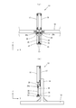
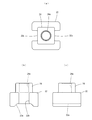
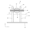
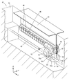
- FIG. 1 It is a schematic front view which shows the state which attaches a skin material fastening clip to a wire with the skin material attachment apparatus of this embodiment. It is a schematic right view which shows the state which attaches a skin material fastening clip to a wire with the skin material attachment apparatus of this embodiment. It is a partially broken perspective view which shows the attachment state of the cushion material to which the skin material of this embodiment is attached, and a skin material fastening clip. It is the perspective view which looked at the cushion material to which the skin material of this embodiment is attached from the bottom face side.
- the X-axis direction is a direction in which a groove 46 of a cushion material 42 such as a seat for attaching a skin material 44 to be described later extends, and is made of a metal that is a locking member in the groove 46 of the cushion material 42 shown in FIGS. This coincides with the longitudinal direction of the wire 40. Furthermore, it is the longitudinal direction of the edge part of the skin material 44, and corresponds to the direction in which the locking end member 48 described later attached to the skin material 44 extends.
- the locking end member 48 provided at the end edge of the skin material 44 is inserted into the groove 46 of the cushion material 42 together with the skin material fastening clip 50, and the skin material fastening clip 50 is attached to the wire 40.
- the Z-axis direction coincides with the depth direction of the cushion material 42 and coincides with a direction perpendicular to the outer surface of the skin material 44 stretched on the cushion material 42.
- a direction orthogonal to the X-axis direction and the Z-axis direction that is the vertical direction is defined as a Y-axis direction.
- the skin material attaching device 10 is arranged at substantially the center of a pair of base parts 12 and above the Z axis direction.
- a pair of support columns 14 are provided, and a beam member 16 is installed above the support columns 14.
- a mounting plate 17 is fixed to the beam member 16 at three predetermined positions in the Z-axis direction, and a drive cylinder 18 serving as a driving device such as three air cylinders is connected to the beam member via the mounting plate 17. 16 is fixed.
- the mounting plates 17 at three positions may be fixed on the beam member 16 so as to be close to or away from each other.
- Each drive cylinder 18 has the same configuration, and includes a cylinder rod 20 that is a push-in member that can move forward and backward in the Z-axis direction.
- a push piece 22 is fixed to the lower end of the cylinder rod 20.
- the push piece 22 is provided with a mounting portion 24 in a convex shape at the top in the Z-axis direction, and the lower end of the cylinder rod 20 is connected to a mounting hole 24 a in the center of the mounting portion 24.
- the lower surface of the push piece 22 is recessed upward, and a pressing recess 22a having a depression that can be stably pushed in just by contacting the skin material fastening clip 50 is formed.
- the pressing recess 22a opens sideways in the X-axis direction, and a locking end member 48 described later is positioned in the communication direction.
- a locking end member 48 described later is positioned in the communication direction.
- guide concave portions 22b extending in the Z-axis direction by cutting up to the side surfaces of the convex portions 24 are formed. Furthermore, when the fitting part etc. which a part of the skin material fastening clip 50 fits are formed in the press recessed part 22a inner surface of the bottom face of the pushing piece 22, the stability of the insertion operation mentioned later becomes high and it is preferable. .
- a pair of guide bars 26 is located at the vertical position where the cylinder rod 20 of each drive cylinder 18 advances and retreats so as to be positioned on both sides of the push piece 22 attached to the cylinder rod 20 on the side surface of the beam member 16.
- Each is provided.
- the pair of guide bars 26 is formed to have a thickness that can be fitted into the guide recess 22 b of the push piece 22, and is pivotally supported by a swing shaft member 28 fixed to the beam member 16. It hangs downward in the direction and is provided so as to be swingable as shown in FIG.
- the swing shaft 28a of the guide bar 26 is provided in the X-axis direction, and the pair of guide bars 26 is provided so as to be swingable in the Y-axis direction.
- a magnet 30 is provided in the lower end portion of the guide bar 26 so as to be attracted to the wire 40. Furthermore, a groove 27 is formed as an engaging portion along the X-axis direction that is the insertion direction of the wire 40 on the distal end surface 26 a that is the lower end of the guide bar 26, and the distal end surface 26 a of the guide bar 26 is formed by the groove 27.
- the wire 40 is stably engaged.
- the guide bar 26 may be urged by a spring or the like so that the front end surface 26a of the guide bar 26 hangs down in parallel with the moving direction of the push piece 22. When the guide bar 26 swings in the Y-axis direction about the swing shaft 28a, it can be swung against the spring bias.
- the drive cylinder 18 include an air cylinder, a hydraulic cylinder, and an electric cylinder.
- the skin material fastening clip 50 is integrally formed of a synthetic resin, has a pair of locking claws 52, and the locking claws 52 are formed to face each other.
- the base end portion of the locking claw 52 is integrally formed from the upper surface of the locking claw base portion 54.
- the locking claw 52 protrudes upward in the Z-axis direction in FIG. 8 and is formed so that the interval in the Y-axis direction increases as it goes upward. is doing.
- the front end portion of the locking claw 52 is held so as to sandwich the locking end member 48 attached to the skin material 44.
- a stopper 53 shown in FIG. 7 is provided on the inner surfaces of the pair of locking claws 52 facing each other, and can engage with the locking groove 49 of the locking end member 48 to fix the position in the X-axis direction. Is provided.
- a hook 56 is integrally provided below the locking claw base 54 provided with the locking claw 52 in the Z-axis direction.
- the hook 56 extends downward in the Z-axis direction and is provided to bend in the Y-axis direction on one side of the pair of locking claws 52. Further, the tip 56a of the hook 56 is bent upward in the Z-axis direction. About 1/2 of the tip end portion 56a in the X-axis direction is excised, and an excised portion 56b is provided.
- the inside of the bent distal end portion 56a of the hook 56 is formed in a groove shape communicating in the X-axis direction, and serves as a wire holding space 57 into which the wire 40 is inserted.
- the skin material trial wearing clip 50 has an almost symmetrical shape across the center line in the X-axis direction, and the width of the hook 56 in the X-axis direction is a constant width that is slightly shorter than the width of the locking claw 52. Is formed.
- a wire guide piece 58 is provided integrally with the locking claw 52 on the side surface of the locking claw 52 facing the tip 56 a of the hook 56.
- the wire guide piece 58 is provided near the middle of the protruding direction of the locking claw 52 and extends downward in the Z-axis direction as the distance from the locking claw 52 increases.
- the wire guide piece 58 is bent at a substantially right angle in the vicinity of the tip end portion 56 a of the hook 56 and extends toward the wire holding space 57.
- the portion extending toward the wire holding space 57 is easily elastically deformed and has an elastic portion 58a formed so that the width in the X-axis direction is about 1 ⁇ 2 compared to the base end side of the wire guide piece 58. It has become.
- the elastic portion 58a is spaced at a predetermined distance from the cut portion 56b of the hook 56, and is bent at a substantially right angle and extends in the wire holding space 57 so as to pass the tip portion 56a of the hook 56.
- the gap between the elastic portion 58a of the wire guide piece 58 and the tip portion 56a of the hook 56 is slightly narrower than the diameter of the wire 40, and becomes an opening into which the wire 40 is inserted.
- a jig receiving portion 60 is integrally provided on the opposite side of the wire holding space 57 of the hook 56 in the Y-axis direction.
- a jig guide piece 62 is provided integrally with the other locking claw 52 so as to face the jig receiving portion 60 in the Z-axis direction.
- the jig receiving portion 60 is located on the side opposite to the hook 56 and extends to the other locking claw 52 side to form a jig holding space 64, and the jig guide piece 62 is placed in the jig holding space 64.
- a jig (not shown) can be guided.
- the skin material attaching device 10 includes, for example, three drive cylinders 18, and has push pieces 22 at the lower end of the cylinder rod 20.
- the cushion member 42 shown in FIG. 9 is placed on the work table (not shown) below each push piece 22 with the bottom surface thereof facing upward, and the wire 40 of the groove 46 and each push piece 22 face each other in the vertical direction. Arrange as follows. Then, by aligning the position of the skin material 44 that covers the cushion material 42, the locking end member 48 is disposed along the groove 46 of the cushion material 42 as shown in FIG. 6.
- the position of the clip 50 for fixing the skin material of the locking end member 48 is set so as to be located immediately below the push piece 22 provided on the cylinder rod 20, and as shown in FIG.
- the bar 26 is inserted into the groove 46, and the groove 27 on the distal end surface 26 a of the guide bar 26 is engaged with the wire 40.
- the magnet 30 at the tip of the guide bar 26 is attracted to the wire 40, and the position of the guide bar 26 is stabilized.
- the push piece 22 is guided by the pair of guide bars 26 and can stably advance and retreat toward the lower wire 40.
- the drive cylinder 18 In the state where the skin material fastening clip 50 is positioned below the push piece 22, the drive cylinder 18 is operated, the cylinder rod 20 is protruded downward in the Z-axis direction, and the push piece 22 is advanced downward. At this time, as shown in FIGS. 6 and 7, the push piece 22 holds the skin material fastening clip 50 in the pressing recess 22 a and stably pushes the skin material fastening clip 50 into the groove 46 of the cushion material 44. . Further, the push piece 22 is lowered while the guide recess 22 a is guided by the pair of guide bars 26, holds the skin material fastening clip 50 stably, and presses it against the wire 40 reliably.
- the drive cylinder 18 is operated in reverse to move the cylinder rod 20 in the retracting direction.
- the cushion material 42 is moved, and the skin material that is not yet locked to the wire 40.
- the driving cylinder 18 is operated in the same manner as described above, and the skin material fastening clip 50 is locked to the wire 40.
- the cushion material 42 may be moved in parallel.
- the guide bar 26 is swung when the cushion material 42 is moved.
- the work location can be easily changed to the groove 46 at the other position of the cushion material 42 by sliding the cushion material 42 on the work table. Thereby, positioning of each groove part 46 of the position from which the cushion material 42 differs can be performed efficiently.
- the skin material 44 and the skin material fastening clip 50 are reliably and stably secured without being fixed to the members provided on the cylinder rod 20 of the skin material attachment device 10.
- the material fastening clip 50 can be locked to the wire 40. Accordingly, the skin material 44 can be quickly and cleanly covered on the cushion material 42, and an automobile seat or the like can be efficiently manufactured.
- the skin material attaching device of the present invention is not limited to the above embodiment, and the locking member may be a member other than a wire, as long as the skin material fastening clip can be engaged.
- the pushing piece may be any shape as long as it can stably press the cover material fastening clip and be locked to the locking member.
- the shape of the guide recess of the push piece may be any shape that can be fitted to the guide bar and slidably guided.
Landscapes
- Engineering & Computer Science (AREA)
- Mechanical Engineering (AREA)
- Manufacturing & Machinery (AREA)
- Textile Engineering (AREA)
- Lining Or Joining Of Plastics Or The Like (AREA)
Abstract
Description
さらに、請求項2乃至5記載の表皮材取り付け装置によれば、より安定且つ確実に表皮材止着用クリップを係止部材側に押圧することができ、係止部材に係止させることができる。
12 基台部
14 支柱
16 梁部材
18 駆動シリンダ
20 シリンダロッド
22 受け駒
22a 押圧凹部
22b ガイド凹部
26 ガイドバー
30 磁石
40 ワイヤ
42 クッション材
44 表皮材
46 溝部
48 係止用端部材
50 表皮材止着用クリップ
Claims (6)
- クッション材(42)を覆う表皮材(44)に取り付けられた表皮材止着用クリップ(50)を、前記クッション材(42)内に設けられた係止部材(40)に係止させる表皮材取り付け装置(10)であって、
前記表皮材(44)に取り付けられた前記表皮材止着用クリップ(50)に上方から接して、前記クッション材(42)の上方から前記表皮材止着用クリップ(50)を前記クッション材(42)内に押し込む押し駒(22)と、
前記押し駒(22)を上下方向に進退させる押し込み部材(20)と、
前記押し込み部材(20)を駆動する駆動装置(18)と、
前記押し駒(22)の両側に位置して、前記押し駒(22)の進退をガイドする一対のガイドバー(26)を備え、
前記押し駒(22)は、前記駆動装置(18)と前記押し込み部材(20)により、前記ガイドバー(26)に沿って進退し、前記押し込み部材(20)が前記クッション材(42)側に進出した位置で、前記表皮材止着用クリップ(50)を前記係止部材(40)に係止させることを特徴とする表皮材取り付け装置。 - 前記押し駒(22)は、前記表皮材止着用クリップ(50)の一部が入り込む窪みを有した押圧凹部(22a)を有する請求項1記載の表皮材取り付け装置。
- 前記押し駒(22)の側面には、前記ガイドバー(26)に嵌合して進退動作をガイドするガイド凹部(22b)を有する請求項1又は2記載の表皮材取り付け装置。
- 前記ガイドバー(26)の先端部には、前記係止部材(40)に吸着する磁石(30)が設けられている請求項1,2又は3記載の表皮材取り付け装置。
- 前記ガイドバー(26)の先端面(26a)には、前記係止部材(40)に係合する係合部(27)が設けられている請求項1,2又は3記載の表皮材取り付け装置。
- 前記ガイドバー(26)は、前記表皮材(44)の端縁部の長手方向及び前記押し駒(22)を上下方向と直交する方向に揺動自在に設けられている請求項1乃至5のいずれか記載の表皮材取り付け装置。
Priority Applications (2)
| Application Number | Priority Date | Filing Date | Title |
|---|---|---|---|
| KR1020197006343A KR102144699B1 (ko) | 2016-09-07 | 2016-09-07 | 표피재 설치 장치 |
| PCT/JP2016/076304 WO2018047253A1 (ja) | 2016-09-07 | 2016-09-07 | 表皮材取り付け装置 |
Applications Claiming Priority (1)
| Application Number | Priority Date | Filing Date | Title |
|---|---|---|---|
| PCT/JP2016/076304 WO2018047253A1 (ja) | 2016-09-07 | 2016-09-07 | 表皮材取り付け装置 |
Publications (1)
| Publication Number | Publication Date |
|---|---|
| WO2018047253A1 true WO2018047253A1 (ja) | 2018-03-15 |
Family
ID=61562614
Family Applications (1)
| Application Number | Title | Priority Date | Filing Date |
|---|---|---|---|
| PCT/JP2016/076304 Ceased WO2018047253A1 (ja) | 2016-09-07 | 2016-09-07 | 表皮材取り付け装置 |
Country Status (2)
| Country | Link |
|---|---|
| KR (1) | KR102144699B1 (ja) |
| WO (1) | WO2018047253A1 (ja) |
Cited By (1)
| Publication number | Priority date | Publication date | Assignee | Title |
|---|---|---|---|---|
| JP2024025372A (ja) * | 2022-08-12 | 2024-02-26 | Ykk株式会社 | 表皮材取付装置、表皮材取付具、表皮材取付具のサスペンダー、および、表皮材取付方法 |
Citations (3)
| Publication number | Priority date | Publication date | Assignee | Title |
|---|---|---|---|---|
| JPH07116363A (ja) * | 1993-10-21 | 1995-05-09 | Araco Corp | ワイヤの位置決め装置 |
| WO2007142363A1 (ja) * | 2006-06-08 | 2007-12-13 | Ts Tech Co., Ltd. | シート表皮吊込み用クリップの自動装着工具 |
| WO2015198430A1 (ja) * | 2014-06-25 | 2015-12-30 | Ykk株式会社 | 表皮材取り付け装置及び座席本体に対する表皮材の取り付け方法 |
Family Cites Families (3)
| Publication number | Priority date | Publication date | Assignee | Title |
|---|---|---|---|---|
| JP2560441Y2 (ja) * | 1991-02-05 | 1998-01-21 | 株式会社サンキ | クッション用表皮材の被覆装置 |
| JPH06225982A (ja) * | 1993-01-30 | 1994-08-16 | Tachi S Co Ltd | ヘッドレストのステー取付用ホルダー付 シートバックの組付方法 |
| JP2001038074A (ja) | 1999-08-03 | 2001-02-13 | T S Tec Kk | シートの吊り込み方法及び装置 |
-
2016
- 2016-09-07 KR KR1020197006343A patent/KR102144699B1/ko active Active
- 2016-09-07 WO PCT/JP2016/076304 patent/WO2018047253A1/ja not_active Ceased
Patent Citations (3)
| Publication number | Priority date | Publication date | Assignee | Title |
|---|---|---|---|---|
| JPH07116363A (ja) * | 1993-10-21 | 1995-05-09 | Araco Corp | ワイヤの位置決め装置 |
| WO2007142363A1 (ja) * | 2006-06-08 | 2007-12-13 | Ts Tech Co., Ltd. | シート表皮吊込み用クリップの自動装着工具 |
| WO2015198430A1 (ja) * | 2014-06-25 | 2015-12-30 | Ykk株式会社 | 表皮材取り付け装置及び座席本体に対する表皮材の取り付け方法 |
Cited By (2)
| Publication number | Priority date | Publication date | Assignee | Title |
|---|---|---|---|---|
| JP2024025372A (ja) * | 2022-08-12 | 2024-02-26 | Ykk株式会社 | 表皮材取付装置、表皮材取付具、表皮材取付具のサスペンダー、および、表皮材取付方法 |
| JP7848081B2 (ja) | 2022-08-12 | 2026-04-20 | Ykk株式会社 | 表皮材取付装置、および、表皮材取付方法 |
Also Published As
| Publication number | Publication date |
|---|---|
| KR20190038871A (ko) | 2019-04-09 |
| KR102144699B1 (ko) | 2020-08-14 |
Similar Documents
| Publication | Publication Date | Title |
|---|---|---|
| CN104337281B (zh) | 表皮材料安装固定用夹具 | |
| CN112440153B (zh) | 便携式加工设备的引导规尺 | |
| JP2020127523A (ja) | クリップ取付具およびクリップ取付装置 | |
| EP2075093B1 (en) | Automatic mounting tool for seat surface fixing clip | |
| US10859767B2 (en) | Optical fiber cutter | |
| JP2015160285A (ja) | Oリング取付装置および方法 | |
| US20210252582A1 (en) | Upper tool stocker | |
| JP2014203735A (ja) | 端子圧着装置 | |
| CN107073739B (zh) | 用于锯的推杆收纳系统和具有这种系统的台锯 | |
| RU2011124918A (ru) | Рабочее оборудование | |
| US20050217128A1 (en) | Guide clamp | |
| JP2011062754A (ja) | クランプ装置 | |
| US7694490B2 (en) | Closing tool assembly | |
| CN104302431B (zh) | 用于固定要借助于加工机加工的工件的装置 | |
| US20050253319A1 (en) | Two-part clamping claw | |
| CN113271816A (zh) | 坐具底盘 | |
| JP2022128150A (ja) | クランプ装置 | |
| KR20190038871A (ko) | 표피재 설치 장치 | |
| JP2015037817A (ja) | 両頭側面フライス盤 | |
| KR101400664B1 (ko) | 절단기의 시편 고정장치 | |
| JP4215698B2 (ja) | 環状ワークの自動装填装置 | |
| JP4223453B2 (ja) | C形クリップの装着治具 | |
| JP2011084056A (ja) | 丸鋸ガイド装置 | |
| CN107081710A (zh) | 部件组装夹具 | |
| CN219703930U (zh) | 一种焊接工装及其夹紧机构 |
Legal Events
| Date | Code | Title | Description |
|---|---|---|---|
| 121 | Ep: the epo has been informed by wipo that ep was designated in this application |
Ref document number: 16915672 Country of ref document: EP Kind code of ref document: A1 |
|
| ENP | Entry into the national phase |
Ref document number: 20197006343 Country of ref document: KR Kind code of ref document: A |
|
| NENP | Non-entry into the national phase |
Ref country code: DE |
|
| 122 | Ep: pct application non-entry in european phase |
Ref document number: 16915672 Country of ref document: EP Kind code of ref document: A1 |
|
| NENP | Non-entry into the national phase |
Ref country code: JP |