WO2018043396A1 - スタンド - Google Patents
スタンド Download PDFInfo
- Publication number
- WO2018043396A1 WO2018043396A1 PCT/JP2017/030724 JP2017030724W WO2018043396A1 WO 2018043396 A1 WO2018043396 A1 WO 2018043396A1 JP 2017030724 W JP2017030724 W JP 2017030724W WO 2018043396 A1 WO2018043396 A1 WO 2018043396A1
- Authority
- WO
- WIPO (PCT)
- Prior art keywords
- stand
- opening
- opening shape
- leg seat
- view
- Prior art date
- Legal status (The legal status is an assumption and is not a legal conclusion. Google has not performed a legal analysis and makes no representation as to the accuracy of the status listed.)
- Ceased
Links
Images










Classifications
-
- F—MECHANICAL ENGINEERING; LIGHTING; HEATING; WEAPONS; BLASTING
- F16—ENGINEERING ELEMENTS AND UNITS; GENERAL MEASURES FOR PRODUCING AND MAINTAINING EFFECTIVE FUNCTIONING OF MACHINES OR INSTALLATIONS; THERMAL INSULATION IN GENERAL
- F16M—FRAMES, CASINGS OR BEDS OF ENGINES, MACHINES OR APPARATUS, NOT SPECIFIC TO ENGINES, MACHINES OR APPARATUS PROVIDED FOR ELSEWHERE; STANDS; SUPPORTS
- F16M11/00—Stands or trestles as supports for apparatus or articles placed thereon ; Stands for scientific apparatus such as gravitational force meters
-
- G—PHYSICS
- G10—MUSICAL INSTRUMENTS; ACOUSTICS
- G10G—REPRESENTATION OF MUSIC; RECORDING MUSIC IN NOTATION FORM; ACCESSORIES FOR MUSIC OR MUSICAL INSTRUMENTS NOT OTHERWISE PROVIDED FOR, e.g. SUPPORTS
- G10G5/00—Supports for musical instruments
-
- H—ELECTRICITY
- H04—ELECTRIC COMMUNICATION TECHNIQUE
- H04R—LOUDSPEAKERS, MICROPHONES, GRAMOPHONE PICK-UPS OR LIKE ACOUSTIC ELECTROMECHANICAL TRANSDUCERS; ELECTRIC HEARING AIDS; PUBLIC ADDRESS SYSTEMS
- H04R1/00—Details of transducers, loudspeakers or microphones
Definitions
- the present invention relates to a stand for supporting an article.
- Patent Documents 1 and 2 below disclose a stand that supports a musical instrument as an article. These stands are configured as tripods with leg seats in contact with the floor surface. A stand having a U-shaped leg seat in plan view is also known.
- the inside of the triangle with the three support points on the tripod as the apex has three tripod legs and a post, so it is not usually available for placing objects. It becomes dead space.
- the stand tends to fall with respect to the side opposite to the opening side. In particular, if an external force is applied due to careless touching of the body, the body may fall.
- An object of the present invention is to provide a stand that can secure a large space that can be used on the inside of a leg seat portion and can effectively prevent the stand from falling to the side substantially opposite to the opening side. .
- a stand (10) having a support (11) for holding an article (SP) and a leg seat (20) to which the support is fixed and facing the floor surface.
- the leg seat portion has an opening shape portion (21) opened in one direction in a plan view, and an end position in a direction opposite to the opening direction of the opening shape portion in a plan view (
- a stand that is formed in a shape that passes through A) and has a straight line (L1) that circumscribes the opening shape portion at outer contact points (B, C) different from the end positions.
- a stand having a column for holding an article, and a leg seat portion to which the column is fixed and facing a floor surface, wherein the leg seat portion (20).
- a support column for holding an article, and a leg seat portion to which the support column is fixed and facing a floor surface, and the leg seat portion connects the support column.
- An opening shape portion that is bifurcated from a connection position to be opened in one direction in a plan view, and the opening shape portion includes a first portion including the connection position, and the opening shape portion from the first portion.
- the second portion is composed of two rod-shaped portions on the opening side, and the average mass per unit length of the second portion is larger than the average mass per unit length of the first portion.
- the present invention it is possible to secure a large space that can be used on the inner side of the leg seat portion and to effectively prevent the stand from falling to the side substantially opposite to the opening side.
- (First embodiment) 1A and 1B are a perspective view and a side view, respectively, of a speaker system to which a stand according to a first embodiment of the present invention is applied.
- a stand 10 supports a speaker device SP as an article.
- the stand 10 includes a leg seat portion 20 and a pole 11 as a support column.
- the leg seat 20 is in contact with the floor.
- the pole 11 has a straight portion 11a (11a1, 11a2) and a curved portion 11b, and a lower end portion 11c of the straight portion 11a is fixed to the leg seat portion 20.
- the straight portion 11a extends in the vertical direction.
- the bending portion 11b is connected to the upper end of the straight portion 11a and is bent in a substantially semicircular shape when viewed from the side.
- the speaker device SP is attached to the tip 11d of the bending portion 11b.
- the straight portion 11a of the pole 11 is formed by connecting two rod-shaped members of a first straight portion 11a1 and a second straight portion 11a2.
- the second straight portion 11a2 is inserted into the first straight portion 11a1, and the two straight portions 11a2 are fixed to the first straight portion 11a1 by fastening them with the fastener 18 at a desired insertion depth. Can be changed. Thereby, the length of the whole straight part 11a can be adjusted. Therefore, the arrangement position of the speaker device SP in the height direction can be adjusted.
- the main unit 13 and the mounting portion 16 are disposed on the second straight portion 11 a 2 of the pole 11.
- the speaker device SP and the mounting unit 16 are electrically connected to the main unit 13.
- the speaker device SP has a left speaker SPL and a right speaker SPR, and can be used for both music reproduction and musical instrument performance reproduction.
- the mounting portion 16 has a function of hooking and holding musical instruments, fixtures, auxiliary tools, devices, and the like.
- the main unit 13 can be connected to a device that outputs an audio signal, such as an electronic musical instrument or a music player.
- the leg seat portion 20 includes an opening shape portion 21 and an extending portion 22, and is configured integrally.
- the leg seat portion 20 is formed of a metal rod, pipe, flat plate or the like.
- the material of the leg seat 20 is not limited to metal as long as strength and weight can be secured, and may be resin or the like.
- the opening shape portion 21 and the extension portion 22 may be formed integrally, or the extension portion 22 may be fixed to the opening shape portion 21 by welding, screwing, or the like.
- the opening shape portion 21 opens in one direction in plan view.
- the opening shape portion 21 is substantially semicircular and has two end portions 21a.
- the extending portion 22 extends from the opening shape portion 21 in a direction opposite to the opening direction of the opening shape portion 21.
- the F direction shown in FIG. 2A is the opening direction.
- the “opposite direction to the opening direction” is a direction perpendicular to the line segment connecting the end positions of the two end portions 21a and is opposite to the opening side, and is the R direction shown in FIG. 2A.
- the opening shape portion 21 is along a virtual circle C1 in a plan view, circumscribes a semicircle that is a half of the virtual circle C1, and extends slightly in the F direction from the circumscribed end position. Therefore, the shape of the opening shape portion 21 is a shape including a semicircle that is a half of the virtual circle C1, but it may not be less than the semicircle.
- the minimum distance between the insides of the two end portions 21a is equal to the diameter of the virtual circle C1, but may not be equal.
- the cross-sectional shape of the opening shape part 21 and the extension part 22 is circular, a polygon may be sufficient and the unusual shape which has a surface facing a floor surface may be sufficient.
- the position where the center of gravity of the stand 10 is projected onto the floor surface that is, the position of the center of gravity of the stand 10 in plan view is defined as G.
- the distal end 22 a of the extending portion 22 is an end position A in the direction opposite to the opening direction of the opening shape portion 21 (R direction).
- L2 be the shortest distance between the center of gravity position G and the straight line L1 in plan view.
- the opening shape of the leg seat part 20 is The stand 10 falls in the urging direction via a state in which the part 21 is supported at one point corresponding to the urging direction.
- the end position A of the stand 10 of the present embodiment is located outside the virtual circle C1, the stand 10 is less likely to fall in the R direction compared to a configuration without the extending portion 22.
- the leg seat portion 20 goes through a state where the end position A and the outer contact B (or the outer contact C) are supported at two points,
- the stand 10 is tilted in a direction perpendicular to a straight line L1 connecting the end position A and the outer contact B (or the outer contact C). Therefore, it is less likely to fall than the case of going through a state where one point is supported, and is stable.
- FIG. 3 is a schematic side view for explaining the stability limit of a general stand.
- the article 121 is supported on the leg seat 120 via a post (not shown).
- the center of gravity of the stand including the article 121 is defined as Gx.
- This stand falls when it tilts more than the angle ⁇ .
- ⁇ d be the amount of displacement of the center of gravity Gx in the horizontal direction from the initial state until the angle ⁇ is inclined. That is, the displacement ⁇ d of the center of gravity Gx in the horizontal direction when the stand is inclined by ⁇ ° with respect to the perpendicular Lx to the floor surface passing through the center of gravity Gx of the stand is substantially Lx ⁇ sin ⁇ .
- the angle ⁇ that can be endured without falling is 10 °. This is a value determined with reference to JISC 9335-1: 2014 “20 Stability and Mechanical Danger (20.1)”, but the employed angle ⁇ is not limited to 10 °.
- the angle ⁇ corresponds to a so-called maximum stable tilt angle.
- the displacement amount ⁇ d of the center of gravity position G in the horizontal direction when the stand 10 is tilted by 10 ° with respect to the perpendicular to the floor surface passing through the center of gravity position G of the stand 10 The shortest distance L2 is longer.
- the shape of the leg seat portion 20, particularly the length of the extended portion 22, is set so that such a condition is satisfied. That is, the length of the extending portion 22 that makes the displacement ⁇ d equal to the shortest distance L2 is set as the design minimum value of the length of the extending portion 22 (or the distance between the gravity center position G and the end position A). Yes. Thereby, the fall of the stand 10 to the direction orthogonal to the R direction or the straight line L1 can be prevented to an inclination of 10 °.
- the maximum value of the length of the extended portion 22 is considered as follows. First, as shown in FIG. 2B, a virtual equilateral triangle T having a centroid that coincides with the centroid position G in a plan view is considered. In this equilateral triangle T, the length of each side is equal to the distance D between the two end portions 21a. In the example of FIG. 2B, the distance D is equal to the diameter of the virtual circle C1. Let the vertices of the equilateral triangle T be P1, P2, and P3. Let L3 be the distance from the center of gravity G, which is also the center of gravity of the regular triangle T, to the vertex P1 of the regular triangle T in plan view.
- the distance from the center of gravity position G to the end position A in the direction parallel to the opening direction of the opening shape portion 21 in the plan view (RF direction) is L4.
- the leg seat part 20 can be arrange
- the following are assumed as usage modes of the speaker system 100.
- a chair is placed inside the opening shape portion 21 of the leg seat portion 20, and the user sits on the chair and listens to music, or plays a musical instrument by himself and listens to the performance sound.
- a sound is heard by standing inside the opening shape portion 21 without placing a chair.
- the speaker device SP can be adjusted to a desired height by appropriately adjusting the total length of the straight portion 11a as described above depending on whether the chair is sitting or standing.
- the leg seat portion 20 has the opening shape portion 21 opened in one direction in plan view, and passes through the end position A in plan view and circumscribes the opening shape portion 21. Since the straight line L1 exists, it is possible to secure a large space that can be used inside the opening shape portion 21 of the leg seat portion 20, and to effectively prevent the stand 10 from overturning to the side substantially opposite to the opening side. it can.
- the leg seat portion 20 can be arranged in a space smaller than a tripod or equilateral triangle leg seat. Further, since the distal end 22a of the extended portion 22 is the end position A in the direction opposite to the opening direction of the opening shape portion 21 (R direction) in plan view, it has a simple shape and is easy to manufacture.
- the opening shape portion 21 circumscribes the virtual circle C1 in a semicircle portion in plan view, and the end position A is located outside the virtual circle C1.
- the opening shape portion 21 may be circumscribed at three or more positions with respect to the virtual circle C1 in a plan view.
- the three points mentioned here include a case where the contact is made in a continuous area as in the example of FIG. Therefore, the example of FIG. 2A also corresponds to a configuration circumscribing at three or more positions.
- Other examples in which the opening shape portion 21 circumscribes the virtual circle C1 at three or more positions will also be described with reference to FIGS.
- FIGS. 4A, B, C, FIGS. 5A, B, 6A, B, and C show the first, second, third, fourth, fifth, sixth, seventh, and eighth modifications of the leg seat portion 20, respectively. It is a top view which shows an example.
- the leg seat portion 20 does not have the extending portion 22, but has an opening shape portion 21 and a sharpened portion 23.
- the sharpened portion 23 is continuous with the opening shape portion 21 and protrudes in a direction opposite to the opening direction of the opening shape portion 21.
- the tip of the sharpened portion 23 is the end position A in the direction opposite to the opening direction of the opening shape portion 21 (R direction).
- the sharpness degree and shape of the sharpened portion 23 are designed so that the shortest distance L2 is longer than the displacement amount ⁇ d, as in the example of FIG. Further, although the virtual equilateral triangle T is not illustrated, the sharpness degree of the sharpened portion 23 is designed so that the distance L4 is shorter than the distance L3 as in the example of FIG. Moreover, the opening shape part 21 circumscribes in the area
- the opening shape portion 21 of the leg seat portion 20 is not semicircular but U-shaped. Also in this example, there are two straight lines L1. The opening shape portion 21 circumscribes the virtual circle C1 at three points in plan view.
- the opening shape portion 21 of the leg seat portion 20 has a shape having a plurality of bending points. Also in this example, there are two straight lines L1. The opening shape portion 21 circumscribes the virtual circle C1 at three points in plan view.
- the opening shape portion 21 of the leg seat portion 20 has two straight portions 24, and the corner formed by the two straight portions 24 is opposite to the opening direction of the opening shape portion 21. Protrudes in the direction. The apex of the corner is the end position A.
- the corner portion formed by the two straight portions 24 can also be regarded as the sharp portion 23 in the first modification (FIG. 4A).
- the outer contact points are innumerable continuous points on the straight line portion 24.
- the opening shape part 21 circumscribes in the area
- the opening shape portion 21 of the leg seat portion 20 does not have an arc-shaped portion and has two straight portions 24.
- the fourth modification (FIG. 5A) is different in that the arc-shaped portion is a straight line, but the behavior related to the fall in the substantially R direction can be considered similarly.
- the opening shape portion 21 circumscribes the virtual circle C1 at four points in plan view.
- the center-of-gravity position G and the end position A are arranged in a direction parallel to the opening direction of the opening shape portion 21 (RF direction).
- the end position A may be shifted in a direction perpendicular to the RF direction.
- the shift direction does not matter.
- the sixth modified example (FIG. 6A) is different from the example of FIGS. 2A and 2B in that the extension position of the extension part 22 is shifted to the left in the drawing, and the other shapes are the same. .
- the leg seat portion 20 is designed so that the shortest distance L2 is longer than the displacement amount ⁇ d and the distance L4 is shorter than the distance L3. Further, the opening shape portion 21 circumscribes the virtual circle C1 in a plan view in a continuous area.
- the seventh modified example (FIG. 6B) is different from the first modified example (FIG. 4A) in that the formation position of the sharp portion 23 is shifted to the left in the figure, and the other shapes are the same. Also in this example, there are two straight lines L1 that pass through the end position A and circumscribe the opening shape portion 21 at outer contacts B and C different from the end position A. Further, the shortest distance L2 is designed to be longer than the displacement amount ⁇ d. Further, the opening shape portion 21 circumscribes the virtual circle C1 in a plan view in a continuous area.
- FIG. 6B is different from the first modified example (FIG. 4A) in that the formation position of the sharp portion 23 is shifted to the left in the figure, and the other shapes are the same. Also in this example, there are two straight lines L1 that pass through the end position A and circumscribe the opening shape portion 21 at outer contacts B and C different from the end position A. Further, the shortest distance L2 is designed to be longer than the displacement amount ⁇ d. Further, the opening shape
- the position of the end position A which is the apex of the corner formed by the two linear portions 24, is shifted to the left in the figure with respect to the fourth modification (FIG. 5A).
- the other shapes are the same.
- the opening shape part 21 circumscribes in the area
- the leg seat portion 20 has been described as being configured as a single unit.
- the leg seat portion 20 may be configured with a plurality of members, and the positional relationship and length may be adjusted.
- the opening shape portion 21 is divided into two members and is configured to be pivotally connected in the vicinity of the center portion so that the size of the distance D in FIG. 2B can be adjusted, so that the apexes P1, P2, P3
- the shape of the regular triangle T formed by the above may be changed.
- you may enable it to adjust the position of the external contacts B and C with respect to the end position A in FIG. 2A.
- the stand 10 can be installed in accordance with the environment of the installation position by adjusting the direction in which it easily falls.
- the extended portion 22 may be configured to be detachable from the opening shape portion 21, and a plurality of extended portions may be prepared so that an extended portion having a desired length can be attached.
- the opening shape portion 21 of the leg seat portion 20 opens in one direction in a bifurcated shape from the connection position 28 where the pole 11 is connected in plan view.
- An extending portion 22 extends rearward from the connection position 28.
- the opening shape portion of the leg seat portion 20 is configured as a separated type, and includes a first portion 21-1 and a second portion 21-2.
- the configuration of the pole 11 and other parts of the stand 10 is the same as that of the first embodiment.
- the first portion 21-1 includes a connection position 28.
- the second portion 21-2 is composed of two rod-like portions on the opening side of the opening shape portion 21 with respect to the first portion 21-1.
- FIG. 8A is a cross-sectional view of the opening-shaped portion 21.
- the first portion 21-1 is a hollow member
- the second portion 21-2 is a solid bar member.
- the male screw 27 of each first part 21-1 is screwed into the female screw 26 provided at the two front ends of the second part 21-2, so that the first part 21-1 Each is attached and fixed to the second portion 21-2 (FIG. 7B).
- the outer diameter of both the first portion 21-1 and the second portion 21-2 is common and has a uniform outer diameter. Both materials are the same. Therefore, due to the difference between hollow and solid, the average mass per unit length of the second portion 21-2 is larger than the average mass per unit length of the first portion 21-1. Yes.
- the center of gravity of the opening shape portion 21 is located on the front side as compared with the case where the opening shape portion 21 is configured by a bar member having a uniform cross-sectional shape. Therefore, since the center of gravity of the stand 10 including the leg seat portion 20 can be easily positioned in the front, it is advantageous for avoiding a fall to the rear.
- the present embodiment it is possible to secure a large space that can be used inside the opening shape portion 21 of the leg seat portion 20 and effectively prevent the stand 10 from falling to the side substantially opposite to the opening side.
- the same effects as those of the first embodiment can be achieved.
- the material of the first portion 21-1 is the first material. 2 may be different from the portion 21-2. Further, on the premise that the same condition is satisfied, the boundary position between the first portion 21-1 and the second portion 21-2 can also adopt an arbitrary position, that is, the length of both can be designed arbitrarily.
- the two parts 21-1 The present invention is not limited to the difference between hollow and solid as described above, and various modifications shown in FIGS. 8B to 8D, 9 and 10 can be employed.
- FIG. 8B, C, and D are side views of a modified opening shape portion 21.
- FIG. 8B the first portion 21-1 and the second portion 21-2 have a common and uniform cross-sectional shape, but the materials of both portions are different, and the specific gravity is the same as that of the first portion 21-1.
- the portion 21-1 may be larger than the second portion 21-2.
- both portions are integrally formed of one kind of material, but the cross-sectional area of the first portion 21-1 may be larger than that of the second portion 21-2.
- FIG. 8D both portions are integrally formed of one kind of material, but the cross-sectional area gradually increases from the first portion 21-1 to the tip of the second portion 21-2. You may do it.
- the cross-sectional area is not limited to gradually changing as in the example of FIG. 8D, and the above condition is satisfied even in a configuration in which the cross-sectional shape irregularly changes in the opening direction of the opening shape portion 21. It is possible to design. From the viewpoint of providing a difference in average mass per unit length by providing the difference between hollow and solid, the first part 21-1 is not necessarily entirely hollow, and the second part 21-2 as a whole need not be solid. That is, the first portion 21-1 may have a hollow portion at least partially, and the second portion 21-2 may have a solid portion at least partially.
- FIG. 9 is a perspective view of the opening shape portion 21 and the weight member.
- a weight member 29 shown in FIG. 9 is prepared.
- the weight member 29 is attached to the stand 10 or purchased after the fact.
- Two weight members 29 are prepared.
- the shape of the opening shape portion 21 does not have to be the separation type as described in FIG.
- the weight member 29 has a semicircular hole 29a.
- the radius of curvature of the hole 29 a is substantially the same as the outer diameter of the opening shape portion 21.
- the user attaches the weight member 29 to the opening shape portion 21 by fitting the hole 29 a and the opening shape portion 21 in the vicinity of the two front ends of the opening shape portion 21.
- the bottom surface of the weight member 29 is flat, and after the attachment, it abuts against the floor surface or faces with a slight gap.
- the weight member 29 is integrated with the opening shape portion 21, and the center of gravity of the opening shape portion 21 including the weight member 29 is located on the front side before the weight member 29 is attached. Therefore, since it becomes easy to position the center of gravity of the entire stand 10 forward, it is advantageous for avoiding falling backward.
- the weight member 29 is made of steel or aluminum.
- the specific gravity of the weight member 29 is desirably larger than that of the opening shape portion 21, but is not limited thereto.
- the weight member 29 may be applied to the separation-type opening-shaped portion 21 described with reference to FIGS. 7 and 8A, and in this case, the weight member 29 is preferably attached near the tip of the second portion 21-2.
- FIG. 10 is a schematic side view for explaining the stability limit of the stand 10.
- the end position of the leg seat 20 in the direction opposite to the opening direction (front) of the opening shape portion 21 (backward) is defined as the origin O.
- the front end (rear end) of the extended portion 22 is the origin O.
- the rear end of the opening shape portion 21 is the origin O.
- the mass of the weight member 29 is m.
- x be the distance from the origin O in the opening direction to the attachment position of the weight member 29.
- the opening direction from the origin O is the X-axis direction
- the upward direction is the Y-axis direction.
- MX the moment sum scalar value in the X-axis direction from the origin O
- MY the moment sum scalar value in the Y-axis direction from the origin.
- the center of gravity of the stand 10 is Gx.
- the speaker system 100 is considered as a stand, and the center of gravity of the entire speaker system 100 is considered as the center of gravity Gx of the stand 10.
- the center of gravity Gx of the stand 10 including them is considered.
- the maximum stable inclination angle of the stand 10 is ⁇
- the mass m and the distance x of the weight member 29 are designed so that Formula 1 is satisfied.
- the article supported by the stand 10 of the present invention is not limited to the speaker device SP, and can hold various articles such as a musical instrument.
- SP Speaker device (article) 10 Stand 11 Pole 20 Leg seat portion 21 Open shape portion 21a End portion 21-1 First portion 21-2 Second portion 22 Extension portion 22a Tip A End position B, C Outer contact L1 Straight line L2 Shortest distance L3, L4 Distance ⁇ d Displacement Quantity C1 Virtual circle D Distance T Virtual equilateral triangle
Landscapes
- Engineering & Computer Science (AREA)
- General Engineering & Computer Science (AREA)
- Physics & Mathematics (AREA)
- Acoustics & Sound (AREA)
- Mechanical Engineering (AREA)
- Multimedia (AREA)
- Signal Processing (AREA)
- Auxiliary Devices For Music (AREA)
Abstract
脚座部の内側に利用可能な大きなスペースを確保すると共に、開口側とは略反対側へのスタンドの転倒を効果的に防止するスタンドを提供する。スタンド10は、脚座部20と、スピーカ装置SPを支持する支柱としてのポール11とを有する。脚座部20は床面に対向当接する。ポール11は脚座部20に固定されている。脚座部20は、平面視で一方向に開口した開口形状部21を有する。脚座部20は、略半円状の開口形状部21と、開口形状部21の開口方向とは反対方向に向かって開口形状部21から延設された延設部22とから成る。平面視において、延設部22の先端22aである端位置Aを通ると共に開口形状部21に対して端位置Aとは異なる外接点B、Cで外接する直線L1が、2本存在する。
Description
本発明は、物品を支持するスタンドに関する。
従来、物品を支持するスタンドが知られている。例えば、下記特許文献1、2には、物品としての楽器を支持するスタンドが開示されている。これらのスタンドは、床面に当接する脚座が三脚として構成される。また、脚座が平面視でコ字状のスタンドも知られている。
しかしながら、脚座が三脚であるスタンドにおいては、三脚における3つの支持点を頂点とする三角形の内側は、三脚の3本の足と支柱とがあるから、通常、物を置く等に利用できずデッドスペースとなる。また、脚座がコ字状のスタンドにおいては、開口側と反対側に対してスタンドが倒れやすい。特に、身体が不用意に触れる等によって外力が加わると転倒するおそれがある。
本発明の目的は、脚座部の内側に利用可能な大きなスペースを確保すると共に、開口側とは略反対側へのスタンドの転倒を効果的に防止することができるスタンドを提供することである。
上記目的を達成するために本発明によれば、物品(SP)を保持する支柱(11)と、前記支柱が固定され、床面に対向する脚座部(20)と、を有するスタンド(10)であって、前記脚座部は、平面視で一方向に開口した開口形状部(21)を有し、且つ、平面視で、前記開口形状部の開口方向とは反対方向における端位置(A)を通ると共に前記開口形状部に対して前記端位置とは異なる外接点(B、C)で外接する直線(L1)が存在する形状に形成されるスタンドが提供される。
上記目的を達成するために本発明によれば、物品を保持する支柱と、前記支柱が固定され、床面に対向する脚座部と、を有するスタンドであって、前記脚座部(20)は、平面視で一方向に開口し且つ平面視で仮想の円(C1)に対して3点以上の位置で外接する開口形状部を有し、平面視で、前記開口形状部の開口方向とは反対方向における前記脚座部の端位置(A)は前記仮想の円の外側に位置するスタンドが提供される。
上記目的を達成するために本発明によれば、物品を保持する支柱と、前記支柱が固定され、床面に対向する脚座部と、を有し、前記脚座部は、前記支柱を接続する接続位置から二股状に平面視で一方向に開口した開口形状部を有し、前記開口形状部は、前記接続位置を含む第1の部分と、前記第1の部分より前記開口形状部の開口側において2つの棒状部分で構成される第2の部分とから成り、前記第1の部分の単位長さ当たりの平均質量よりも、前記第2の部分の単位長さ当たりの平均質量の方が大きいスタンドが提供される。
なお、上記括弧内の符号は例示である。
本発明によれば、脚座部の内側に利用可能な大きなスペースを確保すると共に、開口側とは略反対側へのスタンドの転倒を効果的に防止することができる。
以下、図面を参照して本発明の実施の形態を説明する。
(第1の実施の形態)
図1A、Bはそれぞれ、本発明の第1の実施の形態に係るスタンドが適用されるスピーカシステムの斜視図、側面図である。このスピーカシステム100は、スタンド10に、物品としてのスピーカ装置SPが支持されて成る。スタンド10は、脚座部20と、支柱としてのポール11とを有する。脚座部20は床面に対向当接する。ポール11は、真直部11a(11a1、11a2)と湾曲部11bとを有し、真直部11aの下端部11cが脚座部20に固定されている。真直部11aは鉛直方向に延びている。湾曲部11bは真直部11aの上端に繋がり、側面視で略半円状に湾曲する。湾曲部11bの先端11dにスピーカ装置SPが取り付けられる。
図1A、Bはそれぞれ、本発明の第1の実施の形態に係るスタンドが適用されるスピーカシステムの斜視図、側面図である。このスピーカシステム100は、スタンド10に、物品としてのスピーカ装置SPが支持されて成る。スタンド10は、脚座部20と、支柱としてのポール11とを有する。脚座部20は床面に対向当接する。ポール11は、真直部11a(11a1、11a2)と湾曲部11bとを有し、真直部11aの下端部11cが脚座部20に固定されている。真直部11aは鉛直方向に延びている。湾曲部11bは真直部11aの上端に繋がり、側面視で略半円状に湾曲する。湾曲部11bの先端11dにスピーカ装置SPが取り付けられる。
ポール11の真直部11aは、第1真直部11a1と第2真直部11a2の2本の棒状部材が連結されて成る。例えば、第1真直部11a1に対して第2真直部11a2を挿入し、所望の挿入深さで両者を締結具18で締結することによって、第1真直部11a1に対する第2真直部11a2の固定位置を変えることができる。これにより、真直部11a全体の長さが調整可能になっている。従って、スピーカ装置SPの高さ方向の配置位置を調整できる。ポール11の例えば第2真直部11a2には、メインユニット13、装着部16が配設される。スピーカ装置SP及び装着部16は、メインユニット13に電気的に接続されている。スピーカ装置SPは、左スピーカSPLと右スピーカSPRとを有し、音楽再生、楽器演奏再生のいずれにも用いることができる。装着部16は、楽器、備品、補助具、機器等を引っ掛けたり保持したりする機能を有する。メインユニット13には、音声信号を出力する機器、例えば、電子楽器、音楽プレーヤ等を接続できる。
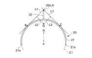
次に、脚座部20の形状について説明し、主として平面視における幾何学的形状を考察する。図2A、Bは、脚座部20の平面図である。脚座部20は、開口形状部21及び延設部22から成り、一体に構成される。脚座部20は、金属の棒やパイプあるいは平板状のもの等で形成される。また、脚座部20の素材は、強度・重量が確保できれば金属に限らず、樹脂などでもよい。開口形状部21と延設部22とは一体に形成されてもよいし、延設部22が開口形状部21に溶接や螺着等で固着されてもよい。開口形状部21は、平面視で一方向に開口している。開口形状部21は略半円状であり、2つの端部21aを有する。延設部22は、開口形状部21の開口方向とは反対方向に向かって、開口形状部21から延設されている。
ここで、図2Aに示すF方向が開口方向である。「開口方向とは反対方向」は、2つの端部21aの端位置を結ぶ線分に垂直な方向であって開口側とは反対の方向であり、図2Aに示すR方向である。開口形状部21は、平面視で仮想の円C1に沿っており、仮想の円C1の半分である半円に対して外接し、外接した端位置からさらに少しF方向に延びている。従って、開口形状部21の形状は、仮想の円C1の半分である半円を包含した形状であるが、半円に満たなくてもよい。2つの端部21aの内側同士の最小間隔は、仮想の円C1の直径と等しいが、等しくなくてもよい。なお、開口形状部21及び延設部22の断面形状は円形であるが、多角形であってもよいし、床面に対向する面を有する異形であってもよい。
図2Aに示すように、スタンド10の重心を床面に投影した位置、すなわち、平面視におけるスタンド10の重心位置をGとする。平面視において、延設部22の先端22aが、開口形状部21の開口方向とは反対方向(R方向)における端位置Aとなる。平面視で端位置Aを通ると共に開口形状部21に対して端位置Aとは異なる外接点B、Cで外接する直線L1が、2本存在する。平面視における重心位置Gと直線L1との最短距離をL2とする。
仮に、脚座部20に延設部22が無い構成で、R方向やR方向から少し角度を有した方向(斜めR方向)へスタンド10が付勢された場合、脚座部20の開口形状部21が付勢方向に対応する1点支持となる状態を経由して、スタンド10が付勢方向へ倒れる。これに対し、本実施の形態のスタンド10は、端位置Aは仮想の円C1の外側に位置するので、延設部22が無い構成に比べ、R方向へ倒れにくくなっている。また、R方向から少しずれた方向へスタンド10が付勢された場合、脚座部20が端位置Aと外接点B(または外接点C)との2点支持となる状態を経由して、端位置Aと外接点B(または外接点C)とを結ぶ直線L1に垂直な方向へスタンド10が倒れる。従って、1点支持となる状態を経由する場合よりも倒れにくく安定する。延設部22が長いほどR方向への転倒には強くなるが、長すぎると配設スペースが大きくなってしまう。そこで、延設部22の長さは以下のような観点で設定されている。
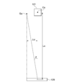
図3は、一般的なスタンドの安定限界を説明する模式的な側面図である。脚座部120に、不図示の支柱を介して物品121が支持されている。物品121を含むスタンドの重心をGxとする。このスタンドは、角度θ以上傾くと転倒する。初期状態から角度θ傾くまでの水平方向における重心Gxの変位量をΔdとする。すなわち、スタンドの重心Gxを通る床面に対する垂線Lxに対してスタンドがθ°傾いたときの水平方向における重心Gxの変位量Δdは、ほぼ、Lx×sinθである。ここで、JIS規格に基づき、本実施の形態のスタンド10では、転倒しないで耐えられる角度θを10°とする。これは、JISC 9335-1:2014「20安定性及び機械的危険(20.1)」を参考にして定めた値であるが、採用する角度θは10°に限定されるものではない。なお、上記角度θは、いわゆる最大安定傾斜角度に該当する。
本実施の形態では、図2Aに示すように、スタンド10の重心位置Gを通る床面に対する垂線に対してスタンド10が10°傾いたときの水平方向における重心位置Gの変位量Δdよりも、最短距離L2の方が長い。このような条件が成立するように、脚座部20の形状、特に延設部22の長さが設定されている。すなわち、変位量Δdが最短距離L2と等しくなるような延設部22の長さを、延設部22の長さ(あるいは重心位置Gと端位置Aとの距離)の設計上の最小値としている。これにより、R方向や直線L1に直交する方向へのスタンド10の転倒を、10°の傾きまで防止することができる。
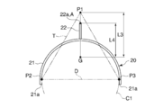
また、延設部22の長さの最大値については次のように考える。まず、図2Bに示すように、平面視で重心位置Gと一致する重心を有する仮想の正三角形Tを考える。この正三角形Tは、各辺の長さが2つの端部21a間の距離Dと等しい。図2Bの例では、距離Dは仮想の円C1の直径と等しい。正三角形Tの頂点をP1、P2、P3とする。平面視で、正三角形Tの重心でもある重心位置Gから、正三角形Tの頂点P1までの距離をL3とする。また、平面視で開口形状部21の開口方向に平行な方向(R-F方向)における重心位置Gから端位置Aまでの距離をL4とする。そして、距離L3よりも距離L4の方が短くなるように、脚座部20の形状、特に延設部22の長さが設定されている。すなわち、L4=L3となるような延設部22の長さを、延設部22の長さ(あるいは重心位置Gと端位置Aとの距離)の設計上の最大値としている。これにより、頂点P1、P2、P3を支持点とする三脚や正三角形の脚座と比べて、よりも小さいスペースに脚座部20を配置できる。従って、延設部22の長さを、上記した最小値と最大値との間の値に設計することで、スタンド10を小さいスペースに効率的に配置できると共に、略R方向への10°までの傾きに耐えられる。
このスピーカシステム100の使用態様として次のようなものが想定される。例えば、脚座部20の開口形状部21の内側に椅子を置き、椅子に座って音楽を聴いたり、自身で楽器を演奏して演奏音を聞いたりする。また、椅子を置かずに開口形状部21の内側に立って音を聞く態様もある。椅子に座る場合と立つ場合とで、上述のように真直部11aの全長を適宜調整することで、スピーカ装置SPを所望の高さへ調整できる。
本実施の形態によれば、脚座部20は、平面視で一方向に開口した開口形状部21を有し、且つ、平面視で端位置Aを通ると共に開口形状部21に対して外接する直線L1が存在するので、脚座部20の開口形状部21の内側に利用可能な大きなスペースを確保すると共に、開口側とは略反対側へのスタンド10の転倒を効果的に防止することができる。
特に、変位量Δdよりも最短距離L2の方が長いので、開口側とは略反対側へのスタンド10の転倒を10°の傾きまで防止することができる。また、平面視で重心位置Gと一致する重心を有し、各辺の長さが2つの端部21a間の距離Dと等しい仮想の正三角形Tの重心から頂点P1までの距離L3よりも、重心位置Gから端位置Aまでの距離L4の方が短いので、三脚や正三角形の脚座よりも小さいスペースに脚座部20を配置することができる。また、平面視において、延設部22の先端22aが、開口形状部21の開口方向とは反対方向(R方向)における端位置Aとなるので、単純な形状であり製造が容易である。
また、開口形状部21は、平面視で仮想の円C1に対して半円部分で外接し、端位置Aは仮想の円C1の外側に位置する。この点でも、開口形状部21の内側に利用可能な大きなスペースを確保すると共に、開口側とは略反対側へのスタンド10の転倒を効果的に防止することができる。なお、この効果を奏するためには、開口形状部21は、平面視で仮想の円C1に対して3点以上の位置で外接すればよい。ここでいう3点には、図2Aの例のように連続した領域で接することで、3点以上の無数の点で接している場合も含まれる。従って、図2Aの例も、3点以上の位置で外接する構成に該当する。開口形状部21が仮想の円C1に対して3点以上の位置で外接する他の例については、図4~図6でも説明する。
図4~図6で脚座部20の変形例を説明する。図4A、B、C、図5A、B、図6A、B、Cは、脚座部20の第1、第2、第3、第4、第5、第6、第7、第8の変形例を示す平面図である。
第1の変形例(図4A)では、脚座部20は延設部22を有するのではなく、開口形状部21と、尖り部23とを有する。尖り部23は開口形状部21と連続しており、開口形状部21の開口方向とは反対方向に突出している。平面視において、尖り部23の先端が、開口形状部21の開口方向とは反対方向(R方向)における端位置Aとなる。この例でも、端位置Aを通ると共に開口形状部21に対して端位置Aとは異なる外接点B、Cで外接する直線L1が、2本存在する。そして、尖り部23の尖り度合いや形状は、図2の例と同様に、変位量Δdよりも最短距離L2の方が長くなるように設計される。また、仮想の正三角形Tについては図示しないが、図2の例と同様に、距離L3よりも距離L4の方が短くなるように尖り部23の尖り度合いが設計される。また、開口形状部21は、平面視で仮想の円C1に対して連続した領域で外接する。
第2の変形例(図4B)では、脚座部20の開口形状部21は半円状でなく、コ字状である。この例でも直線L1が2本存在する。また、開口形状部21は、平面視で仮想の円C1に対して3点で外接する。第3の変形例(図4C)では、脚座部20の開口形状部21は複数の屈曲点を有する形状である。この例でも直線L1が2本存在する。また、開口形状部21は、平面視で仮想の円C1に対して3点で外接する。
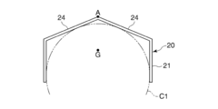
第4の変形例(図5A)では、脚座部20の開口形状部21は2つの直線部24を有し、2つの直線部24が成す角部が開口形状部21の開口方向とは反対方向に突出している。角部の頂点が端位置Aとなる。2つの直線部24が成す角部は、第1の変形例(図4A)における尖り部23と見なすこともできる。第4の変形例の例では、端位置Aを通る外接直線を引くとすると、外接点は、直線部24上の連続した無数の点となる。R方向から少しずれた方向へスタンド10が付勢された場合、直線部24に垂直な方向へスタンド10が倒れる。図2の例のような、端位置Aと外接点との明確な2点支持となる状態を経由しないが、第4の変形例(図5A)でも、倒れに対する耐性は、実質的には図2の例と同等である。また、開口形状部21は、平面視で仮想の円C1に対して連続した領域で外接する。第5の変形例(図5B)では、脚座部20の開口形状部21は弧状部分を有さず、2つの直線部24を有する。第4の変形例(図5A)に対し、弧状部分が直線になっている点が異なるが、略R方向への倒れに関する挙動は同様に考えることができる。また、開口形状部21は、平面視で仮想の円C1に対して4点で外接する。
これまで説明した例では、重心位置Gと端位置Aが開口形状部21の開口方向に平行な方向(R-F方向)に並ぶ構成であった。しかし、第6~第8の変形例(図6A~C)に示すように、端位置AをR-F方向に垂直な方向へシフトさせた形状としてもよい。シフト方向は問わない。まず、第6の変形例(図6A)では、図2A、Bの例に対し、延設部22の延設位置を図の左方にシフトさせた点が異なり、その他の形状は同じである。この例でも、端位置Aを通ると共に開口形状部21に対して端位置Aとは異なる外接点B、Cで外接する直線L1が2本存在する。また、変位量Δdよりも最短距離L2の方が長く且つ、距離L3よりも距離L4の方が短いように脚座部20が設計される。さらに、開口形状部21は、平面視で仮想の円C1に対して連続した領域で外接する。
第7の変形例(図6B)では、第1の変形例(図4A)に対し、尖り部23の形成位置を図の左方にシフトさせた点が異なり、その他の形状は同じである。この例でも、端位置Aを通ると共に開口形状部21に対して端位置Aとは異なる外接点B、Cで外接する直線L1が2本存在する。また、変位量Δdよりも最短距離L2の方が長くなるように設計される。さらに、開口形状部21は、平面視で仮想の円C1に対して連続した領域で外接する。第8の変形例(図6C)では、第4の変形例(図5A)に対し、2つの直線部24が成す角部の頂点である端位置Aの位置を図の左方にシフトさせた点が異なり、その他の形状は同じである。また、開口形状部21は、平面視で仮想の円C1に対して連続した領域で外接する。
また、上述の実施形態及び変形例では、脚座部20は単体で構成されるものとして説明したが、複数の部材で構成され、位置関係や長さが調整できるものとしてもよい。例えば、開口形状部21を2つの部材に分けて中央部付近で回動自在に接続される構成にし、図2Bにおける距離Dの大きさを調整できるようにすることで、頂点P1、P2、P3によって形成される正三角形Tの形状を変更できるようにしてもよい。また、図2Aにおける端位置Aに対する外接点B、Cの位置を調整できるようにしてもよい。これらにより、安定性を若干損なっても、倒れやすい方向を調整することで、設置位置の環境に合わせてスタンド10を設置することができる。また、延設部22は、開口形状部21に対して着脱可能に構成し、長短複数の延設部を用意し、所望の長さの延設部を取り付けることができるようにしてもよい。
(第2の実施の形態)
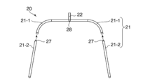
本発明の第2の実施の形態では、脚座部20単体の重心を極力前側に位置するように工夫する。図7A、Bは、本実施の形態における組み付け前、組み付け後の脚座部20の平面図である。脚座部20の開口形状部21は、ポール11を接続する接続位置28から二股状に平面視で一方向に開口している。接続位置28から後方に延設部22が延設される。脚座部20の開口形状部は分離型に構成され、第1の部分21-1と第2の部分21-2とから成る。ポール11をはじめ、スタンド10におけるその他の部分の構成は第1の実施の形態と同様である。第1の部分21-1は接続位置28を含む。第2の部分21-2は、第1の部分21-1より開口形状部21の開口側において2つの棒状部分で構成される。
本発明の第2の実施の形態では、脚座部20単体の重心を極力前側に位置するように工夫する。図7A、Bは、本実施の形態における組み付け前、組み付け後の脚座部20の平面図である。脚座部20の開口形状部21は、ポール11を接続する接続位置28から二股状に平面視で一方向に開口している。接続位置28から後方に延設部22が延設される。脚座部20の開口形状部は分離型に構成され、第1の部分21-1と第2の部分21-2とから成る。ポール11をはじめ、スタンド10におけるその他の部分の構成は第1の実施の形態と同様である。第1の部分21-1は接続位置28を含む。第2の部分21-2は、第1の部分21-1より開口形状部21の開口側において2つの棒状部分で構成される。
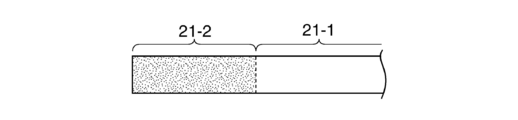
図8Aは、開口形状部21の断面図である。第1の部分21-1は中空部材であり、第2の部分21-2は中実の棒部材である。それぞれの第1の部分21-1が有する雄ねじ27を、第2の部分21-2の前側の2つの端部に設けられた雌ねじ26に螺合することで、第1の部分21-1の各々が第2の部分21-2に取り付けられ固定される(図7B)。第1の部分21-1と第2の部分21-2の両者の外径は共通で、一様の外径寸法となっている。両者の材質も同じである。従って、中空と中実との違いにより、第1の部分21-1の単位長さ当たりの平均質量よりも、第2の部分21-2の単位長さ当たりの平均質量の方が大きくなっている。これにより、一様の断面形状の棒部材で開口形状部21を構成するのに比し、開口形状部21の重心が前側に位置する。よって、脚座部20を含むスタンド10全体としても、重心を前方に位置させることが容易となるので、後方への転倒回避に有利となる。
本実施の形態によれば、脚座部20の開口形状部21の内側に利用可能な大きなスペースを確保すると共に、開口側とは略反対側へのスタンド10の転倒を効果的に防止することに関し、第1の実施の形態と同様の効果を奏することができる。
なお、一様の断面形状の棒部材で開口形状部21を構成するのに比し、開口形状部21の重心が前側に位置するようにすれば、第1の部分21-1の材質は第2の部分21-2と異なっていてもよい。また、同様の条件を満たす前提で、第1の部分21-1と第2の部分21-2との境界位置も任意の位置を採用でき、つまり両者の長さを任意に設計できる。
なお、第1の部分21-1の単位長さ当たりの平均質量よりも、第2の部分21-2の単位長さ当たりの平均質量の方が大きい、という条件を満たすならば、両部分に上記のような中空と中実という違いを設けることに限定されず、図8B~D、図9、図10に示す各種の変形例を採用可能である。
図8B、C、Dは、変形例の開口形状部21の側面図である。図8Bに示すように、第1の部分21-1と第2の部分21-2の両部分の断面形状は共通で一様とするが、両部分の材質を異ならせ、比重は第1の部分21-1の方が第2の部分21-2よりも大きいとしてもよい。あるいは図8Cに示すように、両部分が1種類の材質で一体に形成されるが、断面積は第1の部分21-1の方が第2の部分21-2よりも大きいとしてもよい。あるいは、図8Dに示すように、両部分が1種類の材質で一体に形成されるが、第1の部分21-1から第2の部分21-2の先端にかけて、断面積が徐々に大きくなるようにしてもよい。なお、図8Dの例では、第1の部分21-1と第2の部分21-2との境界を認識できることは必須でなく、ある位置を境界と仮定したとき、上記条件を満たせばよい。
なお、図8Dの例のように断面積が徐々に変化することに限定されず、開口形状部21の開口方向において断面形状が不規則に変化する構成であっても、上記条件を満たすように設計することは可能である。なお、中空と中実という違いを設けることで、両部分に単位長さ当たりの平均質量の違いを設ける観点からは、必ずしも、第1の部分21-1の全体が中空で、第2の部分21-2の全体が中実でなくてもよい。すなわち、第1の部分21-1が少なくとも一部に中空部分を有し、第2の部分21-2が少なくとも一部に中実部分を有する構成としてもよい。
ところで、図9、図10に示すように、開口形状部21に錘部材を予め固定するか、事後的に取り付けることで、スタンド10全体の重心を前方に位置させてもよい。図9は、開口形状部21及び錘部材の斜視図である。例えば、図9に示す錘部材29を用意する。錘部材29はスタンド10に付属するか、事後に購入される。錘部材29は2個用意される。開口形状部21の形状は、図7で説明したような分離タイプである必要はない。錘部材29は半円状の穴29aを有する。穴29aの曲率半径は開口形状部21の外径とほぼ同じである。ユーザは、開口形状部21の2本の前側の先端付近それぞれにおいて穴29aと開口形状部21と嵌めることで、錘部材29を開口形状部21に取り付ける。錘部材29の底面は平坦であり、取り付け後には床面に対して当接するか、またはわずかな隙間を保って対向する。これにより、錘部材29が開口形状部21と一体となり、錘部材29を含む開口形状部21の重心が、錘部材29の取り付け前よりも前側に位置する。よって、スタンド10全体の重心を前方に位置させることが容易となるので、後方への転倒回避に有利となる。
錘部材29は鋼材やアルミニウム等で構成される。なお、錘部材29の比重は開口形状部21よりも大きいことが望ましいが、それに限らない。また、錘部材29は、図7、図8Aで説明した分離タイプの開口形状部21に適用してもよく、その場合は、第2の部分21-2の先端付近に取り付けるのがよい。ところで、錘部材29を、取り付け方式でなく、予め開口形状部21の先端付近に固定する構成を採用してもよい。その場合、錘部材29の固定された部分は断面積が大きくなる。この場合でも、図7で説明した、第1の部分21-1の単位長さ当たりの平均質量よりも第2の部分21-2の単位長さ当たりの平均質量の方が大きいという条件を満たすことが可能である。
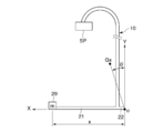
図9に例示した錘部材29の質量と取り付け位置の好ましい設計について図10で説明する。図10は、スタンド10の安定限界を説明する模式的な側面図である。通常使用におけるスタンド10の転倒を回避するための、脚座部20の開口形状部21に対する錘部材29の取り付け位置と錘部材29の質量について考察する。開口形状部21の開口方向(前方)とは反対方向(後方)における脚座部20の端位置を原点Oとする。図10の例では延設部22を有するので、延設部22の先端(後端)が原点Oとなる。なお、延設部22を有しない場合は、開口形状部21の後端が原点Oとなる。錘部材29の質量をmとする。開口方向における原点Oから錘部材29の取り付け位置までの距離をxとする。原点Oから開口方向をX軸方向、上方向をY軸方向とする。また、錘部材29の取り付け前のスタンド10における、原点OからのX軸方向のモーメント総和スカラ値をMXとし、原点からのY軸方向のモーメント総和スカラ値をMYとする。スタンド10の重心をGxとする。なお、ここではスタンド10の転倒を考察するので、スピーカ装置SPが支持されている場合は、スピーカシステム100をスタンドとして考え、スピーカシステム100全体の重心をスタンド10の重心Gxと考える。同様に、装着部16等のように、予めポール11に固定されているものがある場合は、それらも含めてスタンド10の重心Gxを考える。スタンド10の最大安定傾斜角度をθとしたとき、式1が成立するように、錘部材29の質量m及び距離xが設計される。
m≧(MYtanθ-MX)/x ・・・式1
なお、本実施の形態及びその各変形例は、第1の実施の形態に適用してもよい。
m≧(MYtanθ-MX)/x ・・・式1
なお、本実施の形態及びその各変形例は、第1の実施の形態に適用してもよい。
なお、本発明のスタンド10に支持される物品は、スピーカ装置SPに限定されず、楽器等、各種の物品を保持することができる。
以上、本発明をその好適な実施形態に基づいて詳述してきたが、本発明はこれら特定の実施形態に限られるものではなく、この発明の要旨を逸脱しない範囲の様々な形態も本発明に含まれる。
本出願は、2016年8月29日に出願された日本出願第2016-166761号に基づく優先権を主張するものであり、当該日本出願に記載された全内容を本出願に援用する。
SP スピーカ装置(物品)
10 スタンド
11 ポール(支柱)
20 脚座部
21 開口形状部
21a 端部
21-1 第1の部分
21-2 第2の部分
22 延設部
22a 先端
A 端位置
B、C 外接点
L1 直線
L2 最短距離
L3、L4 距離
Δd 変位量
C1 仮想の円
D 距離
T 仮想の正三角形
10 スタンド
11 ポール(支柱)
20 脚座部
21 開口形状部
21a 端部
21-1 第1の部分
21-2 第2の部分
22 延設部
22a 先端
A 端位置
B、C 外接点
L1 直線
L2 最短距離
L3、L4 距離
Δd 変位量
C1 仮想の円
D 距離
T 仮想の正三角形
Claims (11)
- 物品を保持する支柱と、
前記支柱が固定され、床面に対向する脚座部と、を有するスタンドであって、
前記脚座部は、平面視で一方向に開口した開口形状部を有し、且つ、平面視で、前記開口形状部の開口方向とは反対方向における端位置を通ると共に前記開口形状部に対して前記端位置とは異なる外接点で外接する直線が存在する形状に形成されることを特徴とするスタンド。 - 前記スタンドの重心を通る前記床面に対する垂線に対して前記スタンドが10°傾いたときの水平方向における前記重心の変位量よりも、平面視における前記重心と前記直線との最短距離の方が長いことを特徴とする請求項1に記載のスタンド。
- 物品を保持する支柱と、
前記支柱が固定され、床面に対向する脚座部と、を有するスタンドであって、
前記脚座部は、平面視で一方向に開口し且つ平面視で仮想の円に対して3点以上の位置で外接する開口形状部を有し、
平面視で、前記開口形状部の開口方向とは反対方向における前記脚座部の端位置は前記仮想の円の外側に位置することを特徴とするスタンド。 - 前記開口形状部は平面視で略半円状であり、前記開口形状部の開口方向とは反対方向に前記開口形状部から延設部が延設され、前記延設部の先端が前記端位置となることを特徴とする請求項1~3のいずれか1項に記載のスタンド。
- 平面視で前記スタンドの重心と一致する重心を有する仮想の正三角形であって、各辺の長さが前記開口形状部の開口側の2つの端部間の距離と等しい正三角形の重心から、前記正三角形の頂点までの距離よりも、平面視で前記開口方向に平行な方向における前記スタンドの重心から前記端位置までの距離の方が短いことを特徴とする請求項1~4のいずれか1項に記載のスタンド。
- 物品を保持する支柱と、
前記支柱が固定され、床面に対向する脚座部と、を有し、
前記脚座部は、前記支柱を接続する接続位置から二股状に平面視で一方向に開口した開口形状部を有し、
前記開口形状部は、前記接続位置を含む第1の部分と、前記第1の部分より前記開口形状部の開口側において2つの棒状部分で構成される第2の部分とから成り、前記第1の部分の単位長さ当たりの平均質量よりも、前記第2の部分の単位長さ当たりの平均質量の方が大きいスタンド。 - 前記第1の部分は中空部分を有し、前記第2の部分は中実部分を有する請求項6に記載のスタンド。
- 前記開口側における前記第1の部分の2つの端部の各々に、前記棒状部分を構成する棒部材が取り付けられている請求項6または7に記載のスタンド。
- 前記第2の部分は、固定された錘部材を含む請求項6~8のいずれか1項に記載のスタンド。
- 前記錘部材の質量をmとし、
前記開口形状部の開口方向とは反対方向における前記脚座部の端位置を原点とし、
前記開口方向における前記原点から前記錘部材の取り付け位置までの距離をxとし、
前記錘部材の取り付け前の前記スタンドにおける、前記原点からの前記開口方向のモーメント総和スカラ値をMXとし、
前記錘部材の取り付け前の前記スタンドにおける、前記原点からの上方向のモーメント総和スカラ値をMYとし、
前記スタンドの最大安定傾斜角度をθとしたとき、
m≧(MYtanθ-MX)/x
が成立する請求項9に記載のスタンド。 - 前記開口形状部の開口方向とは反対方向に前記開口形状部から延設部が延設される請求項6~10のいずれか1項に記載のスタンド。
Applications Claiming Priority (2)
| Application Number | Priority Date | Filing Date | Title |
|---|---|---|---|
| JP2016-166761 | 2016-08-29 | ||
| JP2016166761 | 2016-08-29 |
Publications (1)
| Publication Number | Publication Date |
|---|---|
| WO2018043396A1 true WO2018043396A1 (ja) | 2018-03-08 |
Family
ID=61300919
Family Applications (1)
| Application Number | Title | Priority Date | Filing Date |
|---|---|---|---|
| PCT/JP2017/030724 Ceased WO2018043396A1 (ja) | 2016-08-29 | 2017-08-28 | スタンド |
Country Status (1)
| Country | Link |
|---|---|
| WO (1) | WO2018043396A1 (ja) |
Citations (5)
| Publication number | Priority date | Publication date | Assignee | Title |
|---|---|---|---|---|
| JPH10307579A (ja) * | 1997-05-07 | 1998-11-17 | Yamaha Miyuujitsuku Trading Kk | 譜面台 |
| JP2000043831A (ja) * | 1998-07-27 | 2000-02-15 | Eido Giken Kogyo Kk | 土のう袋の保持スタンド |
| JP2006030913A (ja) * | 2004-07-21 | 2006-02-02 | Sony Corp | 表示装置用スタンド |
| JP2009025084A (ja) * | 2007-07-18 | 2009-02-05 | Kansai Koji Sokuryo Kk | 測量用三脚 |
| US7514619B1 (en) * | 2005-07-18 | 2009-04-07 | Bruce Harper M | Adjustable musician's stand |
-
2017
- 2017-08-28 WO PCT/JP2017/030724 patent/WO2018043396A1/ja not_active Ceased
Patent Citations (5)
| Publication number | Priority date | Publication date | Assignee | Title |
|---|---|---|---|---|
| JPH10307579A (ja) * | 1997-05-07 | 1998-11-17 | Yamaha Miyuujitsuku Trading Kk | 譜面台 |
| JP2000043831A (ja) * | 1998-07-27 | 2000-02-15 | Eido Giken Kogyo Kk | 土のう袋の保持スタンド |
| JP2006030913A (ja) * | 2004-07-21 | 2006-02-02 | Sony Corp | 表示装置用スタンド |
| US7514619B1 (en) * | 2005-07-18 | 2009-04-07 | Bruce Harper M | Adjustable musician's stand |
| JP2009025084A (ja) * | 2007-07-18 | 2009-02-05 | Kansai Koji Sokuryo Kk | 測量用三脚 |
Similar Documents
| Publication | Publication Date | Title |
|---|---|---|
| US7887138B2 (en) | Integrally formed base arrangement of an office chair | |
| US20050230585A1 (en) | Support apparatus for suspending a display | |
| US20100025439A1 (en) | Nestable hanger with integrated cascade hook | |
| JP5715949B2 (ja) | 食器棚を壁面に固定するための調整可能壁掛食器棚ホルダー群 | |
| CN101687530A (zh) | 踏板的脚背适配器 | |
| JP6119087B2 (ja) | 台座付りん | |
| USD589332S1 (en) | Suction cup clip | |
| US6464189B1 (en) | Hanger device | |
| WO2018043396A1 (ja) | スタンド | |
| US20170278493A1 (en) | Musical instrument | |
| JP4904044B2 (ja) | りん棒 | |
| KR101614933B1 (ko) | 자전거 거치대 | |
| CN209031600U (zh) | 多功能椅子 | |
| JP4318117B2 (ja) | 手摺 | |
| CN105745484B (zh) | 支撑框架 | |
| JP2015047496A (ja) | 手持ち式スリットランプ用台座 | |
| JP7620883B2 (ja) | ゴルフクラブスタンド | |
| CN211288195U (zh) | 一种落地扇的底座及其落地扇 | |
| JP2015119863A (ja) | 家具用の荷重支持部材 | |
| JP6453591B2 (ja) | 机 | |
| JP3210112U (ja) | テーブル | |
| JP6912084B2 (ja) | 机 | |
| JP7489187B2 (ja) | 捩りバネを備える椅子 | |
| JP2011136203A (ja) | 椅子 | |
| KR20220000418U (ko) | 탁상용 달력 |
Legal Events
| Date | Code | Title | Description |
|---|---|---|---|
| 121 | Ep: the epo has been informed by wipo that ep was designated in this application |
Ref document number: 17846401 Country of ref document: EP Kind code of ref document: A1 |
|
| NENP | Non-entry into the national phase |
Ref country code: DE |
|
| 122 | Ep: pct application non-entry in european phase |
Ref document number: 17846401 Country of ref document: EP Kind code of ref document: A1 |
|
| NENP | Non-entry into the national phase |
Ref country code: JP |