WO2018043338A1 - 回転機械 - Google Patents
回転機械 Download PDFInfo
- Publication number
- WO2018043338A1 WO2018043338A1 PCT/JP2017/030558 JP2017030558W WO2018043338A1 WO 2018043338 A1 WO2018043338 A1 WO 2018043338A1 JP 2017030558 W JP2017030558 W JP 2017030558W WO 2018043338 A1 WO2018043338 A1 WO 2018043338A1
- Authority
- WO
- WIPO (PCT)
- Prior art keywords
- groove
- key member
- key
- bearing
- outer ring
- Prior art date
- Legal status (The legal status is an assumption and is not a legal conclusion. Google has not performed a legal analysis and makes no representation as to the accuracy of the status listed.)
- Ceased
Links
Images



Classifications
-
- F—MECHANICAL ENGINEERING; LIGHTING; HEATING; WEAPONS; BLASTING
- F04—POSITIVE - DISPLACEMENT MACHINES FOR LIQUIDS; PUMPS FOR LIQUIDS OR ELASTIC FLUIDS
- F04D—NON-POSITIVE-DISPLACEMENT PUMPS
- F04D29/00—Details, component parts, or accessories
- F04D29/05—Shafts or bearings, or assemblies thereof, specially adapted for elastic fluid pumps
- F04D29/056—Bearings
- F04D29/059—Roller bearings
-
- F—MECHANICAL ENGINEERING; LIGHTING; HEATING; WEAPONS; BLASTING
- F04—POSITIVE - DISPLACEMENT MACHINES FOR LIQUIDS; PUMPS FOR LIQUIDS OR ELASTIC FLUIDS
- F04D—NON-POSITIVE-DISPLACEMENT PUMPS
- F04D29/00—Details, component parts, or accessories
- F04D29/05—Shafts or bearings, or assemblies thereof, specially adapted for elastic fluid pumps
- F04D29/056—Bearings
-
- F—MECHANICAL ENGINEERING; LIGHTING; HEATING; WEAPONS; BLASTING
- F16—ENGINEERING ELEMENTS AND UNITS; GENERAL MEASURES FOR PRODUCING AND MAINTAINING EFFECTIVE FUNCTIONING OF MACHINES OR INSTALLATIONS; THERMAL INSULATION IN GENERAL
- F16C—SHAFTS; FLEXIBLE SHAFTS; ELEMENTS OR CRANKSHAFT MECHANISMS; ROTARY BODIES OTHER THAN GEARING ELEMENTS; BEARINGS
- F16C19/00—Bearings with rolling contact, for exclusively rotary movement
- F16C19/02—Bearings with rolling contact, for exclusively rotary movement with bearing balls essentially of the same size in one or more circular rows
- F16C19/04—Bearings with rolling contact, for exclusively rotary movement with bearing balls essentially of the same size in one or more circular rows for radial load mainly
-
- F—MECHANICAL ENGINEERING; LIGHTING; HEATING; WEAPONS; BLASTING
- F16—ENGINEERING ELEMENTS AND UNITS; GENERAL MEASURES FOR PRODUCING AND MAINTAINING EFFECTIVE FUNCTIONING OF MACHINES OR INSTALLATIONS; THERMAL INSULATION IN GENERAL
- F16C—SHAFTS; FLEXIBLE SHAFTS; ELEMENTS OR CRANKSHAFT MECHANISMS; ROTARY BODIES OTHER THAN GEARING ELEMENTS; BEARINGS
- F16C19/00—Bearings with rolling contact, for exclusively rotary movement
- F16C19/02—Bearings with rolling contact, for exclusively rotary movement with bearing balls essentially of the same size in one or more circular rows
- F16C19/04—Bearings with rolling contact, for exclusively rotary movement with bearing balls essentially of the same size in one or more circular rows for radial load mainly
- F16C19/06—Bearings with rolling contact, for exclusively rotary movement with bearing balls essentially of the same size in one or more circular rows for radial load mainly with a single row or balls
-
- F—MECHANICAL ENGINEERING; LIGHTING; HEATING; WEAPONS; BLASTING
- F16—ENGINEERING ELEMENTS AND UNITS; GENERAL MEASURES FOR PRODUCING AND MAINTAINING EFFECTIVE FUNCTIONING OF MACHINES OR INSTALLATIONS; THERMAL INSULATION IN GENERAL
- F16C—SHAFTS; FLEXIBLE SHAFTS; ELEMENTS OR CRANKSHAFT MECHANISMS; ROTARY BODIES OTHER THAN GEARING ELEMENTS; BEARINGS
- F16C19/00—Bearings with rolling contact, for exclusively rotary movement
- F16C19/22—Bearings with rolling contact, for exclusively rotary movement with bearing rollers essentially of the same size in one or more circular rows, e.g. needle bearings
- F16C19/24—Bearings with rolling contact, for exclusively rotary movement with bearing rollers essentially of the same size in one or more circular rows, e.g. needle bearings for radial load mainly
- F16C19/26—Bearings with rolling contact, for exclusively rotary movement with bearing rollers essentially of the same size in one or more circular rows, e.g. needle bearings for radial load mainly with a single row of rollers
-
- F—MECHANICAL ENGINEERING; LIGHTING; HEATING; WEAPONS; BLASTING
- F16—ENGINEERING ELEMENTS AND UNITS; GENERAL MEASURES FOR PRODUCING AND MAINTAINING EFFECTIVE FUNCTIONING OF MACHINES OR INSTALLATIONS; THERMAL INSULATION IN GENERAL
- F16C—SHAFTS; FLEXIBLE SHAFTS; ELEMENTS OR CRANKSHAFT MECHANISMS; ROTARY BODIES OTHER THAN GEARING ELEMENTS; BEARINGS
- F16C33/00—Parts of bearings; Special methods for making bearings or parts thereof
- F16C33/30—Parts of ball or roller bearings
- F16C33/58—Raceways; Race rings
-
- F—MECHANICAL ENGINEERING; LIGHTING; HEATING; WEAPONS; BLASTING
- F16—ENGINEERING ELEMENTS AND UNITS; GENERAL MEASURES FOR PRODUCING AND MAINTAINING EFFECTIVE FUNCTIONING OF MACHINES OR INSTALLATIONS; THERMAL INSULATION IN GENERAL
- F16C—SHAFTS; FLEXIBLE SHAFTS; ELEMENTS OR CRANKSHAFT MECHANISMS; ROTARY BODIES OTHER THAN GEARING ELEMENTS; BEARINGS
- F16C33/00—Parts of bearings; Special methods for making bearings or parts thereof
- F16C33/30—Parts of ball or roller bearings
- F16C33/58—Raceways; Race rings
- F16C33/583—Details of specific parts of races
- F16C33/586—Details of specific parts of races outside the space between the races, e.g. end faces or bore of inner ring
-
- F—MECHANICAL ENGINEERING; LIGHTING; HEATING; WEAPONS; BLASTING
- F16—ENGINEERING ELEMENTS AND UNITS; GENERAL MEASURES FOR PRODUCING AND MAINTAINING EFFECTIVE FUNCTIONING OF MACHINES OR INSTALLATIONS; THERMAL INSULATION IN GENERAL
- F16C—SHAFTS; FLEXIBLE SHAFTS; ELEMENTS OR CRANKSHAFT MECHANISMS; ROTARY BODIES OTHER THAN GEARING ELEMENTS; BEARINGS
- F16C35/00—Rigid support of bearing units; Housings, e.g. caps, covers
- F16C35/04—Rigid support of bearing units; Housings, e.g. caps, covers in the case of ball or roller bearings
- F16C35/06—Mounting or dismounting of ball or roller bearings; Fixing them onto shaft or in housing
- F16C35/063—Fixing them on the shaft
-
- F—MECHANICAL ENGINEERING; LIGHTING; HEATING; WEAPONS; BLASTING
- F16—ENGINEERING ELEMENTS AND UNITS; GENERAL MEASURES FOR PRODUCING AND MAINTAINING EFFECTIVE FUNCTIONING OF MACHINES OR INSTALLATIONS; THERMAL INSULATION IN GENERAL
- F16C—SHAFTS; FLEXIBLE SHAFTS; ELEMENTS OR CRANKSHAFT MECHANISMS; ROTARY BODIES OTHER THAN GEARING ELEMENTS; BEARINGS
- F16C35/00—Rigid support of bearing units; Housings, e.g. caps, covers
- F16C35/04—Rigid support of bearing units; Housings, e.g. caps, covers in the case of ball or roller bearings
- F16C35/06—Mounting or dismounting of ball or roller bearings; Fixing them onto shaft or in housing
- F16C35/067—Fixing them in a housing
-
- F—MECHANICAL ENGINEERING; LIGHTING; HEATING; WEAPONS; BLASTING
- F16—ENGINEERING ELEMENTS AND UNITS; GENERAL MEASURES FOR PRODUCING AND MAINTAINING EFFECTIVE FUNCTIONING OF MACHINES OR INSTALLATIONS; THERMAL INSULATION IN GENERAL
- F16C—SHAFTS; FLEXIBLE SHAFTS; ELEMENTS OR CRANKSHAFT MECHANISMS; ROTARY BODIES OTHER THAN GEARING ELEMENTS; BEARINGS
- F16C35/00—Rigid support of bearing units; Housings, e.g. caps, covers
- F16C35/04—Rigid support of bearing units; Housings, e.g. caps, covers in the case of ball or roller bearings
- F16C35/06—Mounting or dismounting of ball or roller bearings; Fixing them onto shaft or in housing
- F16C35/07—Fixing them on the shaft or housing with interposition of an element
- F16C35/077—Fixing them on the shaft or housing with interposition of an element between housing and outer race ring
-
- H—ELECTRICITY
- H02—GENERATION; CONVERSION OR DISTRIBUTION OF ELECTRIC POWER
- H02K—DYNAMO-ELECTRIC MACHINES
- H02K7/00—Arrangements for handling mechanical energy structurally associated with dynamo-electric machines, e.g. structural association with mechanical driving motors or auxiliary dynamo-electric machines
- H02K7/08—Structural association with bearings
- H02K7/083—Structural association with bearings radially supporting the rotary shaft at both ends of the rotor
-
- F—MECHANICAL ENGINEERING; LIGHTING; HEATING; WEAPONS; BLASTING
- F16—ENGINEERING ELEMENTS AND UNITS; GENERAL MEASURES FOR PRODUCING AND MAINTAINING EFFECTIVE FUNCTIONING OF MACHINES OR INSTALLATIONS; THERMAL INSULATION IN GENERAL
- F16C—SHAFTS; FLEXIBLE SHAFTS; ELEMENTS OR CRANKSHAFT MECHANISMS; ROTARY BODIES OTHER THAN GEARING ELEMENTS; BEARINGS
- F16C2322/00—Apparatus used in shaping articles
- F16C2322/39—General buildup of machine tools, e.g. spindles, slides, actuators
Definitions
- the present disclosure relates to a rotating machine including a bearing that supports a rotating shaft of an impeller.
- Patent Document 1 discloses an anti-rotation mechanism in which a long hole that penetrates a housing that supports an outer ring and reaches the middle of the outer ring in the radial direction is provided, and a pin is inserted into the long hole.
- Patent Documents 2 and 3 disclose a bearing device having a detent mechanism for inserting a key member in the direction of the rotation axis.
- This disclosure describes a rotating machine that can stably prevent the rotation of the outer ring following the rotation of the inner ring of the bearing while eliminating the influence of the thermal expansion of the rotating shaft.
- One aspect of the present disclosure is formed in a bearing that supports a rotation shaft of an impeller, a bearing support portion that supports an outer periphery of the bearing, a bearing and a bearing support portion, and extends along a rotation axis direction of the rotation shaft.
- a rolling element that includes a key groove and a key member that is inserted into the key groove, and the bearing includes an inner ring that is attached to the rotating shaft, an outer ring that is supported by the bearing support portion, and an inner ring and an outer ring.
- the bearing support portion includes an outer restricting portion capable of abutting on one end portion in the rotation axis direction of the key member inserted into the key groove, and the outer ring is inserted into the key groove.
- This is a rotating machine that includes an inner restricting portion that can come into contact with the other end of the key member, and the distance between the outer restricting portion and the inner restricting portion is longer than the length of the key member in the rotation axis direction.
- FIG. 1 is a cross-sectional view of an electric compressor according to an embodiment of the present disclosure.
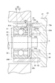
- 2 is an enlarged cross-sectional view of the bearing of FIG. 3A and 3B show the relationship between the key member and the key groove.
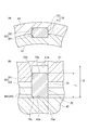
- FIG. 3A is a cross-sectional view taken along line III (a) -III (a) in FIG. 2
- FIG. 3B is a cross-sectional view taken along line (b) -III (b).
- FIG. 4 is an exploded perspective view showing an assembled state of the bearing and the bearing support portion.
- FIG. 5 is a perspective view showing a sleeve externally mounted on the outer ring of the bearing.
- FIG. 6 is a perspective view showing a state in which a bearing retainer and a coil spring are mounted in the sleeve.
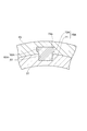
- FIG. 7 is a cross-sectional view showing a relationship between a key member and a key groove according to a modified example.
- One aspect of the present disclosure is formed in a bearing that supports a rotation shaft of an impeller, a bearing support portion that supports an outer periphery of the bearing, a bearing and a bearing support portion, and extends along a rotation axis direction of the rotation shaft.
- a rolling element that includes a key groove and a key member that is inserted into the key groove, and the bearing includes an inner ring that is attached to the rotating shaft, an outer ring that is supported by the bearing support portion, and an inner ring and an outer ring.
- the bearing support portion includes an outer restricting portion capable of abutting on one end portion in the rotation axis direction of the key member inserted into the key groove, and the outer ring is inserted into the key groove.
- This is a rotating machine that includes an inner restricting portion that can come into contact with the other end of the key member, and the distance between the outer restricting portion and the inner restricting portion is longer than the length of the key member in the rotation axis direction.
- the outer ring can be prevented from rotating by the key member inserted in the keyway.
- movement of the key member inserted into the key groove in the direction of the rotation axis is restricted by the outer restriction portion of the bearing support portion and the inner restriction portion of the outer ring. Therefore, in this rotating machine, it is possible to prevent the key member from falling off in the usage mode, and to stably prevent the outer ring from rotating.
- the distance between the outer restricting portion and the inner restricting portion is longer than the length of the key member in the rotation axis direction. Accordingly, a gap is formed between at least one of the outer restricting portion and the inner restricting portion and the key member, and the elongation caused by the thermal expansion of the rotating shaft can be absorbed. As a result, in this rotating machine, it is possible to stably prevent the rotation of the outer ring following the rotation of the inner ring of the bearing and to eliminate the influence of the thermal expansion of the rotating shaft.
- the key groove includes an inner groove provided on the outer periphery of the outer ring and an outer groove provided on the inner periphery of the bearing support portion, and at least one of both ends of the key member.
- the insertion guide can be a taper.
- the taper portion facilitates insertion into the inner groove or the outer groove and facilitates adjustment of the circumferential displacement.
- the insertion guide portion may be a rotating machine provided at an end portion on the inner regulating portion side.
- the key member is temporarily fixed in an outer groove provided in the bearing support portion, and the bearing support portion can be assembled to the bearing in this state.
- the insertion guide portion is provided at the end portion on the inner regulating portion side of both the end portions of the key member, it is possible to effectively adjust the circumferential shift of the inner groove and the outer groove at the time of assembly.
- the area where the key member fits can be a rotating machine where the outer groove is larger than the inner groove.
- An attempt to make the inner groove larger than the outer groove tends to increase the size of the outer ring from the viewpoint of securing the strength of the bearing.
- the outer groove is made larger than the inner groove, it is easy to suppress an increase in the size of the outer ring of the bearing, which is advantageous for downsizing.
- the bearing support portion includes a cylindrical portion that is externally mounted on the outer ring, an annular pressing portion that contacts the outer ring in the cylindrical portion, and an elastic portion that elastically supports the pressing portion in the rotation axis direction.
- the holding portion includes a retracting portion that avoids the key member in the cylindrical portion, and the retracting area formed by the inner periphery of the cylindrical portion and the retracting portion is a rotary machine that has a gap in the circumferential direction of the rotating shaft with respect to the key member. can do.
- the retraction area can be arcuate. If it is made into a bow shape, processing will become easy and workability will improve.
- the key groove includes an inner groove provided on the outer periphery of the outer ring and an outer groove provided on the inner periphery of the bearing support portion, and the outer groove has a wide width on the back side in the radial direction.
- the key member can be a rotary machine that is fitted in the outer groove and includes a drop-off preventing portion that protrudes in the width direction perpendicular to the longitudinal direction of the outer groove. For example, when the key member is temporarily fixed in an outer groove provided in the bearing support portion and the bearing support portion is assembled to the bearing in this state, the key member is prevented from falling off, so that the assembling workability is improved.
- the radially inner side of the outer groove means the centrifugal direction side with respect to the rotation axis.
- the electric compressor 1 is applied to, for example, an internal combustion engine of a vehicle or a ship.
- the electric compressor 1 includes a compressor unit 7.
- the electric compressor 1 rotates a compressor impeller (an example of an impeller) 8 by the interaction of the rotor portion 13 and the stator portion 14, compresses a fluid such as air, and generates compressed air.
- a motor 5 is formed by the rotor portion 13 and the stator portion 14.
- the electric compressor 1 includes a rotating shaft 12 that is rotatably supported in the housing 2, and a compressor impeller 8 that is fixed to a distal end portion (one end portion) 12 a of the rotating shaft 12.
- the housing 2 includes a motor housing 3 that houses the motor 5 (the rotor portion 13 and the stator portion 14), and an inverter housing 4 that closes an opening on the other end side (right side in the drawing) of the motor housing 3.
- a compressor housing 6 that houses the compressor impeller 8 is provided on one end side (the left side in the drawing) of the motor housing 3.
- the compressor housing 6 includes a suction port 9, a scroll portion 10, and a discharge port 11.
- aluminum is suitable for the motor housing 3 and the inverter housing 4 because they are advantageous in terms of weight reduction.
- stainless steel or carbon steel can also be employed.
- the rotor portion 13 is fixed to the central portion of the rotation shaft 12 in the direction of the rotation axis X, and includes one or more permanent magnets (not shown) attached to the rotation shaft 12.
- the stator portion 14 is fixed to the inner surface of the motor housing 3 so as to surround the rotor portion 13, and includes a coil portion (not shown) formed by winding a conductive wire.
- the electric compressor 1 includes two bearings 20A and 20B that rotatably support the rotary shaft 12 with respect to the housing 2.
- the bearings 20 ⁇ / b> A and 20 ⁇ / b> B are arranged so as to sandwich the motor 5, and support the rotating shaft 12 with both ends.
- One bearing 20 ⁇ / b> A is provided at an end of the motor housing 3 on the compressor impeller 8 side.
- the other bearing 20B is attached to the support wall 23 on the inverter housing 4 side.
- the support wall portion 23 protrudes from the inverter housing 4 toward the inside.
- the inverter housing 4 has a mechanism for supplying a drive current to the stator portion 14.
- the inverter housing 4 includes a disk-shaped end wall portion 21 that closes the opening on the other end side of the motor housing 3, and a peripheral wall portion 22 that connects the outer peripheral portion of the end wall portion 21 and the motor housing 3.
- a conductive wire connected to the stator portion 14 is accommodated in the peripheral wall portion 22.
- the end wall portion 21 is made of, for example, aluminum.
- the above-described support wall portion (an example of a bearing support portion) 23 is an inner side in the rotation axis X direction from the center of the end wall portion 21, that is, the motor 5 side (end wall portion shown in FIG. 1).
- 21 left side of 21
- a cylindrical sleeve receiver 42 protruding further inward from the pedestal 41
- a sleeve (an example of a cylindrical portion) 43 externally mounted on the sleeve receiver 42.
- the sleeve 43 is integrated with the sleeve receiver 42 by, for example, press fitting or screw fastening.
- the outer ring 51 of the bearing 20B is fitted into the sleeve 43 and is in contact therewith.
- the support wall portion 23 is disposed between the pedestal portion 41 and the pressing plate 44 in the sleeve receiver 42 and an annular pressing plate 44 (an example of a pressing portion) that contacts the outer ring 51 of the bearing 20 ⁇ / b> B in the sleeve 43. And a coil spring (an example of an elastic portion) 45 that presses the pressing plate 44 against the outer ring 51.
- the sleeve 43 and the sleeve receiver 42 are formed as separate members, but may be integrated.
- the bearing 20B includes, for example, an inner ring 52 attached to the rotary shaft 12 by press fitting or fitting with a gap, the above-described outer ring 51, and a rolling element 53 interposed between the inner ring 52 and the outer ring 51. It is a ball bearing.
- the bearing 20 ⁇ / b> B is supported by the support wall portion 23 via the sleeve 43.
- the inner ring 52 rotates following the rotation of the rotating shaft 12.
- the rotating shaft 12 is made of a metal such as an SCM material, and thermally expands in accordance with temperature conditions and extends in the direction of the rotating axis X.
- the bearing 20B also moves (displaces) following the extension of the rotating shaft 12, so that play that can absorb this deviation is also necessary.
- a structure that restricts the rotation of the outer ring 51 and can absorb a shift in elongation due to thermal expansion of the rotating shaft 12 will be described in detail.
- relative rotation of the outer ring 51 and the sleeve 43 is restricted by a key member 70 inserted into the key groove 60.
- the key groove 60 extends along the rotation axis X of the rotary shaft 12, and the key member 70 is a substantially rectangular block body inserted into the key groove 60.
- the key member 70 inserted into the key groove 60 is slightly allowed to move in the direction of the rotational axis X while being restricted from moving in the rotational direction.
- the key groove 60 includes an inner groove 61 provided on the outer periphery of the outer ring 51 and an outer groove 62 provided on the inner periphery of the sleeve 43.
- one end is an end on the side that fits in the sleeve 43, and the other end is on the opposite side along the rotation axis X direction. It is an end. That is, one end of the outer ring 51 is an end opposite to the compressor impeller 8 (right end in FIG. 1), and the other end is an end on the compressor impeller 8 side (FIG. 1).
- the inner groove 61 is formed so as to cut out a part of one end portion of the outer ring 51.
- the width of the inner groove 61 that is, the dimension in the direction orthogonal to the rotation axis X corresponds to the width of the key member 70. That is, the width of the inner groove 61 is a width that allows the key member 70 to be accommodated and restricts movement of the key member 70 in the rotation direction.
- the length of the inner groove 61 that is, the dimension in the direction along the rotation axis X may be long enough to accommodate a part of the key member 70 in the longitudinal direction (direction of the rotation axis X).
- the outer groove 62 is provided on the inner periphery of the sleeve 43 and extends along the rotation axis X. Further, the outer groove 62 vertically cuts the inner periphery of the sleeve 43 so as to linearly communicate from the end on the side where the bearing 20 ⁇ / b> B is inserted to the end on the opposite side of the inner periphery of the sleeve 43.
- the width of the outer groove 62 corresponds to the width of the key member 70, and is a width in which the key member 70 can be accommodated and the movement of the key member 70 in the rotation direction can be restricted.
- the length of the outer groove 62 substantially corresponds to the length along the rotation axis X of the sleeve 43. For example, the depth of the outer groove 62 is deeper than the depth of the inner groove 61.
- the inner groove 61 and the outer groove 62 overlap each other and are combined to form a single key groove 60.
- the key member 70 inserted into the key groove 60 includes an inner interference portion 71 near the rotating shaft 12 and an outer interference portion 72 on the opposite side (see FIG. 3A).
- the entire outer interference portion 72 is accommodated in the outer groove 62 in the direction (longitudinal direction) along the rotation axis X.
- the inner interference part 71 is only accommodated in the inner groove 61 in the longitudinal direction.
- the outer groove 62 is larger than the inner groove 61 in the region where the key member 70 fits in the key groove 60.
- the depth of the outer groove 62 is deeper than the depth of the inner groove 61.
- the area of the key member 70 that can be accommodated in the key groove 60 is the inner area.
- the outer groove 62 is larger than the groove 61.
- the inner groove 61 is larger than the outer groove 62 in the area of the key member 70 that is confined to the key groove 60.
- trying to make the inner groove 61 larger than the outer groove 62 tends to increase the size of the outer ring 51 from the viewpoint of securing the strength of the bearing 20B.
- the outer groove 62 is made larger than the inner groove 61 as in the present embodiment, it is easy to suppress an increase in the size of the outer ring 51 of the bearing 20B, which is advantageous for downsizing the entire bearing 20B. .
- the pressing plate 44 that contacts the outer ring 51 and a coil spring 45 that presses the pressing plate 44 toward the outer ring 51.
- the pressing plate 44 is annular and has a center hole 44d through which the end of the rotating shaft 12 is inserted.
- the holding plate 44 is formed with a spring receiving surface 44a for receiving the coil spring 45, and a rib 44b protruding along the outer edge is provided on the surface opposite to the spring receiving surface 44a, that is, the surface facing the outer ring 51. It has been. The tips of the ribs 44b are in contact with the outer ring 51.
- the holding plate 44 includes a retracting portion 44 c that avoids the key member 70 in the sleeve 43.
- the retracting portion 44c contacts the key member 70 and prevents the key member 70 from falling off in cooperation with the inner groove 61.
- the retracting portion 44c has a shape such that, for example, an area formed by an arc and a chord is cut away from the circular pressing plate 44. As a result, an arcuate retraction area Ar is formed between the retraction portion 44 c of the pressing plate 44 and the inner periphery of the sleeve 43.
- the “bow shape” when viewed from the direction along the rotation axis X, the “bow shape” is surrounded by an outline line including a convex curve (arc) portion and a straight line portion connecting both ends of the convex curve portion. Means part.
- the cross section of the retreat area Ar is at least larger than the cross sectional area of the key member 70, and in particular, a gap is formed in the circumferential direction of the rotary shaft 12 with respect to the key member 70.
- a portion of the presser plate 44 other than the retreat area AR that is, a portion of the outer periphery of the presser plate 44 other than the retracting portion 44 c extends to the outside in the radial direction from the key member 70.
- the distance from the rotation axis X to a portion other than the retracting portion 44c is longer than the distance from the rotating axis X to the retracting portion 44c contacting the key member 70.
- the retreat area Ar is not limited to an arcuate shape as long as it has one of the functions of preventing interference when the key member 70 is attached and preventing the relative rotation of the pressing plate 44.
- the arch shape improves the workability compared to a complicated shape.
- the retreat area Ar having both the function of preventing the interference with the key member 70 when mounting the pressing plate 44 and the function of preventing the relative rotation of the pressing plate 44 with respect to the key member 70 is provided. It can be formed easily.
- the support wall portion 23 includes the sleeve receiver 42 on which the sleeve 43 is externally mounted.
- the front end surface of the sleeve receiver 42 can be brought into contact with one end portion 70a in the longitudinal direction (direction along the rotation axis X) of the key member 70 having a rectangular block shape. That is, the tip surface is an outward regulating portion 42a (see FIG. 3B) that regulates movement of the key member 70 in the direction along the rotation axis X.
- the outer ring 51 includes a wall surface that closes the inner groove 61 in the direction of the rotation axis X, and the wall surface can contact the other end portion 70 b of the key member 70.
- this wall surface is an inward regulating portion 61 a that regulates the direction along the rotation axis X of the key member 70.
- “contactable” means that when the key member 70 moves in the longitudinal direction of the key groove 60 (the direction along the rotation axis X), the movement can be regulated by contact.
- the distance D between the outer restricting portion 42 a and the inner restricting portion 61 a is longer than the length L of the key member 70 in the longitudinal direction. Therefore, a gap is formed between at least one of the outer restricting portion 42 a and the inner restricting portion 61 a and the key member 70.
- the elongation due to the thermal expansion of the rotating shaft 12 can be absorbed.
- the elongation ⁇ H due to the thermal expansion of the rotating shaft 12 is expressed by the following equation (1).
- ⁇ H H ⁇ ⁇ ⁇ T (1)
- H Distance between bearings (see Fig. 1)
- ⁇ Linear expansion coefficient of the rotating shaft
- T Temperature rise of a predetermined representative part (rotating shaft, bearing, etc.) before and after operation
- the key member 70 has a substantially rectangular block shape, and is inserted into the key groove 60 so that the longitudinal direction is along the longitudinal direction of the key groove 60. Of both ends in the longitudinal direction of the key member 70, one is an end portion 70a on the outer restricting portion 42a side, and the other is an end portion 70b on the inner restricting portion 61a side.
- tapered portions 70c and 70d are formed on both the end portion 70a on the outer restricting portion 42a side and the end portion 70b on the inner restricting portion 61a side.
- the taper portions 70c and 70d are an example of an insertion guide portion that adjusts the circumferential displacement of the inner groove 61 and the outer groove 62 that are arranged to face each other. Note that the insertion guide portion only needs to be able to adjust the circumferential displacement of the inner groove 61 and the outer groove 62.
- a slope portion having an inclined surface may be formed.
- the key member 70 can be installed in advance by temporarily fixing the key member 70 in the outer groove 62 of the sleeve 43.
- the outer groove 62 and the inner groove 61 are aligned, and the circumferential shift is adjusted to form one key groove 60. There is a need.
- the taper portion 70 d of the key member 70 contacts the outer ring 51 to rotate the outer ring 51, thereby causing the outer groove 51 to rotate.
- the deviation in the circumferential direction of the inner groove 61 with respect to 62 is adjusted. As a result, workability during assembly is improved.
- the key member 70 according to the present embodiment is provided with a tapered portion 70c at the end portion 70a on the outer regulating portion 42a side. Therefore, even when the key member 70 is installed in the inner groove 61 of the outer ring 51 in advance and the assembling work is performed in the reverse procedure to the above, the benefit of improving workability during assembling can be enjoyed.
- the tapered portions 70c and 70d are provided at both ends 70a and 70b of the key member 70. However, depending on the actual assembly operation process, the tapered portions 70c and 70d are inserted into either one of them. A guide part may be provided.
- the key groove 60 ⁇ / b> A includes an inner groove 61 provided on the outer periphery of the outer ring 51 and an outer groove 62 ⁇ / b> A provided on the inner periphery of the sleeve 43.
- the outer groove 62A is wide on the back side in the radial direction.
- the back side in the radial direction means the outside in the radial direction.
- the rear side in the radial direction means the side away from the rotating shaft 12, that is, the centrifugal direction side with respect to the rotating shaft 12.
- the key member 70 ⁇ / b> A includes an inner interference portion 71 that fits in the inner groove 61 and an outer interference portion 72 ⁇ / b> A that fits in the outer groove 62.
- the outer interference part 72 ⁇ / b> A is provided with a drop-off prevention part 72 a that projects in the width direction orthogonal to the longitudinal direction of the outer groove 62.
- a drop-off prevention part 72 a that projects in the width direction orthogonal to the longitudinal direction of the outer groove 62.
- the rotation of the outer ring 51 can be prevented by the key members 70 and 70A inserted into the key grooves 60 and 60A.
- the movement of the key members 70 and 70A inserted in the key grooves 60 and 60A in the direction of the rotation axis X is restricted by the outer restriction portion 42a of the support wall portion 23 and the inner restriction portion 61a of the outer ring 51. Yes. Therefore, in these embodiments, it is possible to prevent the outer ring 51 from rotating stably by preventing dropout in the usage mode.
- the distance between the outer restricting portion 42 a and the inner restricting portion 61 a is longer than the length of the key member 70 in the rotation axis X direction.
- a gap is formed between at least one of the outer restricting portion 42 a and the inner restricting portion 61 a and the key member 70, and the elongation caused by the thermal expansion of the rotating shaft 12 can be absorbed.
- the present disclosure is applicable to any rotating machine in which the bearing includes a bearing that supports the rotating shaft.
- the present disclosure can be applied to a type of electric supercharger that includes a turbine and assists rotation by a motor, and can also be applied to a general supercharger other than the electric supercharger.
- the present disclosure is not limited to a rotary machine including a compressor, and the present disclosure can also be applied to a generator that generates power by a turbine.
- the inverter housing is not limited to an aspect in which the inverter housing is connected in the axial direction with respect to the motor housing, and may be in a form in which the inverter housing is connected radially outward.
- the inverter housing may be provided on the top of the motor housing.
Landscapes
- Engineering & Computer Science (AREA)
- General Engineering & Computer Science (AREA)
- Mechanical Engineering (AREA)
- Power Engineering (AREA)
- Mounting Of Bearings Or Others (AREA)
- Structures Of Non-Positive Displacement Pumps (AREA)
- Rolling Contact Bearings (AREA)
- Support Of The Bearing (AREA)
Abstract
Description
H:軸受間距離(図1参照)
α:回転軸の線膨張係数
T:運転前後の所定代表部(回転軸や軸受など)の温度上昇分
8 コンプレッサインペラ(インペラ)
12 回転軸
20B 軸受
23 支持壁部(軸受支持部)
42a 外方規制部
43 スリーブ(筒部)
44 押さえ板(押さえ部)
44c 退避部
51 外輪
52 内輪
53 転動体
60 キー溝
61a 内方規制部
61 内溝
62 外溝
70 キー部材
70c,70d テーパ部(挿入ガイド部)
72a 脱落防止部
Ar 退避領域
L キー部材の長さ
Claims (8)
- インペラの回転軸を支持する軸受と、
前記軸受の外周を支持する軸受支持部と、
前記軸受と前記軸受支持部とに形成され、前記回転軸の回転軸線方向に沿って延在するキー溝と、
前記キー溝に挿入されるキー部材と、を備え、
前記軸受は、前記回転軸に取り付けられた内輪と、前記軸受支持部に支持された外輪と、前記内輪と前記外輪との間に介在する転動体と、を備え、
前記軸受支持部は、前記キー溝内に挿入された前記キー部材の前記回転軸線方向の一方の端部に当接可能な外方規制部を備え、
前記外輪は、前記キー溝内に挿入された前記キー部材の他方の端部に当接可能な内方規制部を備え、
前記外方規制部と前記内方規制部との距離は、前記キー部材の前記回転軸線方向の長さよりも長い、回転機械。 - 前記キー溝は、前記外輪の外周に設けられた内溝と、前記軸受支持部の内周に設けられた外溝とを備え、
前記キー部材の両方の前記端部のうち、少なくとも一方には、互いに対向配置される前記内溝及び前記外溝の周方向のずれを調整する挿入ガイド部が設けられている請求項1記載の回転機械。 - 前記挿入ガイド部はテーパ部である、請求項2記載の回転機械。
- 前記挿入ガイド部は、前記内方規制部側の前記端部に設けられている、請求項2または3記載の回転機械。
- 前記キー部材が収まる領域は前記内溝よりも前記外溝の方が大きい、請求項2~4のいずれか一項記載の回転機械。
- 前記軸受支持部は、前記外輪に外装された筒部と、前記筒部内で前記外輪に当接する環状の押さえ部と、前記回転軸線方向において前記押さえ部を前記外輪側に押圧する弾性部と、を備え、
前記押さえ部は、前記筒部内で前記キー部材を避ける退避部を備え、
前記筒部の内周と前記退避部とによって形成される退避領域は、前記キー部材に対して前記回転軸の周方向に隙間を有する、請求項1~5のいずれか一項記載の回転機械。 - 前記退避領域は、弓形状である、請求項6記載の回転機械。
- 前記キー溝は、前記外輪の外周に設けられた内溝と、前記軸受支持部の内周に設けられた外溝とを備え、
前記外溝は、径方向の奥側の幅が広く、
前記キー部材は、前記外溝内に収まると共に、前記外溝の長手方向に直交する幅方向に張り出した脱落防止部を備える、請求項1~7のいずれか一項記載の回転機械。
Priority Applications (4)
| Application Number | Priority Date | Filing Date | Title |
|---|---|---|---|
| JP2018537227A JP6680360B2 (ja) | 2016-09-01 | 2017-08-25 | 回転機械 |
| CN201780049999.0A CN109563845B (zh) | 2016-09-01 | 2017-08-25 | 旋转机械 |
| DE112017004388.3T DE112017004388B4 (de) | 2016-09-01 | 2017-08-25 | Rotationsmaschine |
| US16/325,579 US10662963B2 (en) | 2016-09-01 | 2017-08-25 | Rotary machine |
Applications Claiming Priority (2)
| Application Number | Priority Date | Filing Date | Title |
|---|---|---|---|
| JP2016171001 | 2016-09-01 | ||
| JP2016-171001 | 2016-09-01 |
Publications (1)
| Publication Number | Publication Date |
|---|---|
| WO2018043338A1 true WO2018043338A1 (ja) | 2018-03-08 |
Family
ID=61301903
Family Applications (1)
| Application Number | Title | Priority Date | Filing Date |
|---|---|---|---|
| PCT/JP2017/030558 Ceased WO2018043338A1 (ja) | 2016-09-01 | 2017-08-25 | 回転機械 |
Country Status (5)
| Country | Link |
|---|---|
| US (1) | US10662963B2 (ja) |
| JP (1) | JP6680360B2 (ja) |
| CN (1) | CN109563845B (ja) |
| DE (1) | DE112017004388B4 (ja) |
| WO (1) | WO2018043338A1 (ja) |
Cited By (2)
| Publication number | Priority date | Publication date | Assignee | Title |
|---|---|---|---|---|
| CN114876965A (zh) * | 2022-06-17 | 2022-08-09 | 山东朗澈轴承有限公司 | 一种适用于高载荷深沟球轴承套圈组件 |
| WO2022172652A1 (ja) * | 2021-02-09 | 2022-08-18 | 株式会社Ihi | 電動圧縮機 |
Families Citing this family (3)
| Publication number | Priority date | Publication date | Assignee | Title |
|---|---|---|---|---|
| DE112017004388B4 (de) * | 2016-09-01 | 2025-09-11 | Ihi Corporation | Rotationsmaschine |
| JP2024018551A (ja) | 2022-07-29 | 2024-02-08 | 三菱重工コンプレッサ株式会社 | 遠心圧縮機 |
| JP2025017452A (ja) * | 2023-07-25 | 2025-02-06 | 株式会社豊田自動織機 | 電動圧縮機 |
Citations (3)
| Publication number | Priority date | Publication date | Assignee | Title |
|---|---|---|---|---|
| JPH0632749U (ja) * | 1992-10-02 | 1994-04-28 | 愛知機械工業株式会社 | ベアリングの固定構造 |
| JP2003013981A (ja) * | 2001-06-27 | 2003-01-15 | Koyo Seiko Co Ltd | 転がり軸受の取付け構造 |
| JP2015007451A (ja) * | 2013-06-25 | 2015-01-15 | 日本精工株式会社 | 転がり軸受装置 |
Family Cites Families (19)
| Publication number | Priority date | Publication date | Assignee | Title |
|---|---|---|---|---|
| US4046432A (en) * | 1976-06-09 | 1977-09-06 | Fidelity Electric Company, Incorporated | Bearing assembly and anchor therefor |
| JPS6335818U (ja) | 1986-08-21 | 1988-03-08 | ||
| JPH0462418U (ja) | 1990-09-29 | 1992-05-28 | ||
| JP3671447B2 (ja) * | 1995-01-30 | 2005-07-13 | アイシン精機株式会社 | 軸受保持構造 |
| US6250815B1 (en) * | 1999-06-24 | 2001-06-26 | Zf Meritor, Llc | Temperature compensating carrier bearing assembly |
| KR100406062B1 (ko) * | 2001-06-12 | 2003-11-17 | 미래산업 주식회사 | 핸들러의 챔버용 팬장치 |
| DE60214090T2 (de) | 2001-06-27 | 2007-03-15 | Jtekt Corp., Osaka | Wälzlagermontage |
| JP2006194418A (ja) | 2005-01-17 | 2006-07-27 | Nsk Ltd | 転がり軸受装置 |
| JP5067144B2 (ja) * | 2007-12-05 | 2012-11-07 | 株式会社ジェイテクト | 軸受装置 |
| JP2010048301A (ja) | 2008-08-20 | 2010-03-04 | Nsk Ltd | 軸受装置 |
| JP5428658B2 (ja) | 2009-08-31 | 2014-02-26 | 株式会社Ihi | ターボ機械 |
| CN102359499A (zh) | 2011-10-26 | 2012-02-22 | 中电电机股份有限公司 | 具有轴向缓冲作用的轴承 |
| JP2014105732A (ja) | 2012-11-26 | 2014-06-09 | Jtekt Corp | 転がり軸受 |
| JP2014152923A (ja) | 2013-02-14 | 2014-08-25 | Jtekt Corp | 転がり軸受 |
| CN104061245A (zh) | 2014-05-09 | 2014-09-24 | 安徽安风风机有限公司 | 主轴用滚动轴承轴向随动装置 |
| JP2015218591A (ja) * | 2014-05-14 | 2015-12-07 | 株式会社豊田自動織機 | 電動過給機 |
| JP2016056828A (ja) | 2014-09-05 | 2016-04-21 | 株式会社豊田自動織機 | ターボ機械 |
| JP6550947B2 (ja) * | 2015-06-11 | 2019-07-31 | 株式会社Ihi | 回転機械 |
| DE112017004388B4 (de) * | 2016-09-01 | 2025-09-11 | Ihi Corporation | Rotationsmaschine |
-
2017
- 2017-08-25 DE DE112017004388.3T patent/DE112017004388B4/de active Active
- 2017-08-25 WO PCT/JP2017/030558 patent/WO2018043338A1/ja not_active Ceased
- 2017-08-25 CN CN201780049999.0A patent/CN109563845B/zh active Active
- 2017-08-25 JP JP2018537227A patent/JP6680360B2/ja active Active
- 2017-08-25 US US16/325,579 patent/US10662963B2/en active Active
Patent Citations (3)
| Publication number | Priority date | Publication date | Assignee | Title |
|---|---|---|---|---|
| JPH0632749U (ja) * | 1992-10-02 | 1994-04-28 | 愛知機械工業株式会社 | ベアリングの固定構造 |
| JP2003013981A (ja) * | 2001-06-27 | 2003-01-15 | Koyo Seiko Co Ltd | 転がり軸受の取付け構造 |
| JP2015007451A (ja) * | 2013-06-25 | 2015-01-15 | 日本精工株式会社 | 転がり軸受装置 |
Cited By (6)
| Publication number | Priority date | Publication date | Assignee | Title |
|---|---|---|---|---|
| WO2022172652A1 (ja) * | 2021-02-09 | 2022-08-18 | 株式会社Ihi | 電動圧縮機 |
| JPWO2022172652A1 (ja) * | 2021-02-09 | 2022-08-18 | ||
| JP7643471B2 (ja) | 2021-02-09 | 2025-03-11 | 株式会社Ihi | 電動圧縮機 |
| US12535077B2 (en) | 2021-02-09 | 2026-01-27 | Ihi Corporation | Electric compressor |
| CN114876965A (zh) * | 2022-06-17 | 2022-08-09 | 山东朗澈轴承有限公司 | 一种适用于高载荷深沟球轴承套圈组件 |
| CN114876965B (zh) * | 2022-06-17 | 2024-02-20 | 山东朗澈轴承有限公司 | 一种适用于高载荷深沟球轴承套圈组件 |
Also Published As
| Publication number | Publication date |
|---|---|
| JP6680360B2 (ja) | 2020-04-15 |
| CN109563845B (zh) | 2021-05-28 |
| JPWO2018043338A1 (ja) | 2019-04-25 |
| DE112017004388T5 (de) | 2019-05-09 |
| DE112017004388B4 (de) | 2025-09-11 |
| US10662963B2 (en) | 2020-05-26 |
| US20190178257A1 (en) | 2019-06-13 |
| CN109563845A (zh) | 2019-04-02 |
Similar Documents
| Publication | Publication Date | Title |
|---|---|---|
| WO2018043338A1 (ja) | 回転機械 | |
| EP3926171B1 (en) | Scroll compressor, vehicle air conditioner and vehicle | |
| US9784178B2 (en) | Variable displacement exhaust turbocharger equipped with variable nozzle mechanism | |
| JP5772924B2 (ja) | スクリュー圧縮機 | |
| CN103511260B (zh) | 旋转压缩机 | |
| US5130592A (en) | Sliding rotor motor | |
| JP2007228683A (ja) | アウターロータ型モータ | |
| CN110319003B (zh) | 动涡盘驱动组件和涡旋式压缩机 | |
| KR20230169229A (ko) | 시일 장치 및 회전 기계 및 시일 장치의 장착 방법 | |
| CN209545264U (zh) | 一种电机定子装配组件及其应用的外转子电机 | |
| US6252321B1 (en) | Endshield assembly with alignable bearing for an electric motor | |
| EP3657023B1 (en) | Motor | |
| KR100840222B1 (ko) | 로터리 베인 압축기 | |
| JP6007084B2 (ja) | 電動モータ及びファンモータ | |
| JP6658861B2 (ja) | 回転機械 | |
| JP2010133530A (ja) | 軸受構造及び該軸受構造を備えた過給機 | |
| US7503757B2 (en) | Oil pump having rotor receiving portion for restriction moving range of an outer rotor in a direction perpendicular to an eccentric direction | |
| CN208782616U (zh) | 一种电机 | |
| CN107749684B (zh) | 外转子电机和具有其的流体驱动装置 | |
| CN205533240U (zh) | 旋转式机械 | |
| CN111365293B (zh) | 压缩机转子、压缩机及空调设备 | |
| JP4066474B2 (ja) | 回転機械 | |
| CN217445140U (zh) | 转子轴系结构、电机和电器 | |
| CN220440433U (zh) | 定子组件及外转子电机 | |
| CN113982937B (zh) | 偏心轴组件、涡旋压缩机、空调器 |
Legal Events
| Date | Code | Title | Description |
|---|---|---|---|
| 121 | Ep: the epo has been informed by wipo that ep was designated in this application |
Ref document number: 17846343 Country of ref document: EP Kind code of ref document: A1 |
|
| ENP | Entry into the national phase |
Ref document number: 2018537227 Country of ref document: JP Kind code of ref document: A |
|
| 122 | Ep: pct application non-entry in european phase |
Ref document number: 17846343 Country of ref document: EP Kind code of ref document: A1 |
|
| WWG | Wipo information: grant in national office |
Ref document number: 112017004388 Country of ref document: DE |