WO2018043163A1 - 車両用情報表示装置 - Google Patents
車両用情報表示装置 Download PDFInfo
- Publication number
- WO2018043163A1 WO2018043163A1 PCT/JP2017/029672 JP2017029672W WO2018043163A1 WO 2018043163 A1 WO2018043163 A1 WO 2018043163A1 JP 2017029672 W JP2017029672 W JP 2017029672W WO 2018043163 A1 WO2018043163 A1 WO 2018043163A1
- Authority
- WO
- WIPO (PCT)
- Prior art keywords
- vehicle
- unit
- mirror
- state
- side mirror
- Prior art date
- Legal status (The legal status is an assumption and is not a legal conclusion. Google has not performed a legal analysis and makes no representation as to the accuracy of the status listed.)
- Ceased
Links
Images





Classifications
-
- B—PERFORMING OPERATIONS; TRANSPORTING
- B60—VEHICLES IN GENERAL
- B60R—VEHICLES, VEHICLE FITTINGS, OR VEHICLE PARTS, NOT OTHERWISE PROVIDED FOR
- B60R1/00—Optical viewing arrangements; Real-time viewing arrangements for drivers or passengers using optical image capturing systems, e.g. cameras or video systems specially adapted for use in or on vehicles
- B60R1/02—Rear-view mirror arrangements
- B60R1/06—Rear-view mirror arrangements mounted on vehicle exterior
Definitions
- the present invention relates to a vehicle information display device.
- This application claims priority based on Japanese Patent Application No. 2016-168380 filed on August 30, 2016, and incorporates all the description content described in the above Japanese application.
- the instrument panel or display in the vehicle is provided with various warning lights for displaying the state of the vehicle, for example, the lighting state of a headlamp, a lamp, etc., the operation state of the parking brake, and the like.
- a user who is an occupant can check the state of the vehicle from the display on the instrument panel.
- there is a vehicle information display device that detects a vehicle, a pedestrian, or the like that travels in a blind spot around the vehicle and displays a warning on a side mirror while the vehicle is traveling for example, Patent Document 1).
- the vehicle information display device includes a display unit that displays information on a mirror surface of a side mirror provided in a vehicle when an occupant gets on or off, an illuminance sensor that detects illuminance in the side mirror, When the display unit displays information, the comparison unit compares the illuminance detected by the illuminance sensor and a predetermined value, and the mirror angle adjustment unit rotates the mirror surface of the side mirror in the elevation direction. When the illuminance detected by the illuminance sensor is greater than or equal to a predetermined value, the mirror surface is rotated in a direction in which the elevation angle is small or the depression angle is large. And a control unit that causes the output unit to output an angle adjustment signal instructing.
- the present application can be realized not only as a vehicle information display device including such a characteristic processing unit, but also as a vehicle information display method using such characteristic processing as a step. Can be realized as a program for causing a computer to execute. Further, it can be realized as a semiconductor integrated circuit that realizes part or all of the vehicle information display device, or can be realized as another system including the vehicle information display device.
- the purpose of the present disclosure is to ensure visibility by automatically adjusting the elevation angle of the mirror surface of the side mirror to an angle that is easy to see from the user outside the vehicle when displaying information on the mirror surface of the side mirror when getting on or off the vehicle. It is possible to provide a vehicle information display device that can notify information to a user outside the vehicle more effectively.
- a vehicle information display device includes a display unit that displays information on a mirror surface of a side mirror provided in a vehicle when an occupant gets on or off the vehicle, and an illuminance sensor that detects illuminance in the side mirror.
- the comparison unit that compares the illuminance detected by the illuminance sensor and a predetermined value
- the mirror angle adjustment unit that rotates the mirror surface of the side mirror in the elevation direction
- An output unit that outputs an angle adjustment signal that instructs rotation of the mirror surface of the side mirror, and the mirror surface in a direction in which the elevation angle is small or the depression angle is large when the illuminance detected by the illuminance sensor is a predetermined value or more.
- a control unit that causes the output unit to output an angle adjustment signal instructing the rotation.
- the control unit sends an angle adjustment signal from the output unit to the mirror angle.
- the mirror surface is rotated in a direction in which the elevation angle is small or the depression angle is large. Accordingly, the elevation angle of the mirror surface can be automatically adjusted to an angle at which external light such as sunlight is not reflected to the user, and the visibility of the user can be ensured (see FIGS. 9A and 9B).
- the control unit instructs rotation of the mirror surface in a direction in which an elevation angle is increased in a range where the illuminance detected by the illuminance sensor is less than a predetermined value.
- a configuration in which the angle adjustment signal is output to the output unit is preferable.
- the mirror surface of the side mirror is rotated in the direction in which the depression angle increases in the range where the illuminance at the side mirror is less than a predetermined value. Therefore, the elevation angle of the mirror surface can be easily adjusted by a user outside the vehicle and can be automatically adjusted to an angle at which external light such as sunlight is not reflected to the user, and the visibility of the user can be ensured.
- the elevation angle detection unit that detects the elevation angle of the mirror surface of the side mirror, and the angle detected by the elevation angle detection unit is such that the elevation angle of the mirror surface is a predetermined maximum elevation angle, and the illuminance sensor When the illuminance detected in (1) is equal to or greater than the predetermined value, a configuration including a warning unit that issues a warning is preferable.
- the warning unit can notify that the information is displayed on the side mirror by issuing a warning.
- the elevation angle detection unit for detecting the elevation angle of the mirror surface of the side mirror and the elevation angle of the mirror surface of the side mirror detected by the elevation angle detection unit before rotating the mirror surface are stored.
- the control unit when the display unit stops displaying information, until the elevation angle detected by the elevation angle detection unit coincides with the elevation angle stored in the storage unit, It is preferable that the output unit output an angle adjustment signal that instructs rotation of the mirror surface.
- the storage unit stores the elevation angle before rotating the mirror surface in the elevation direction.
- the control unit outputs an angle adjustment signal from the output unit to the mirror angle adjustment unit until the elevation angle of the mirror surface matches the elevation angle stored in the storage unit. Therefore, when the display of information on the side mirror is finished, the elevation angle of the mirror surface of the side mirror can be returned to an elevation angle that is easy to see from the user in the vehicle.
- the vehicle information display device includes a vehicle state detection unit that detects the state of the vehicle, and a determination unit that determines whether or not the state detected by the vehicle state detection unit is a predetermined state. And a display detecting unit that detects the passenger getting off, and the display unit detects the passenger getting off the detecting unit, and the determining unit determines that the predetermined state is not present,
- the structure which displays the information which shows the state detected in the vehicle state detection part on the said mirror surface of the said side mirror is preferable.
- the predetermined state includes an on / off state of various switches that should be in parking, an operation state of the operation unit, and the like. For example, an on / off state of a switch for lighting an indoor lamp, an on / off state of a headlamp, an operating state of a parking brake, an up / down state of a window, etc. For this reason, when the vehicle is not in a predetermined state when the user gets off, the user can take necessary measures according to the state of the vehicle.
- a portable device detection unit that detects a portable device in the vehicle is provided, and the display unit detects the passenger getting off in the getting-off detection unit, and the portable device in the vehicle is detected in the portable device detection unit.
- information indicating that the portable device is in the vehicle is displayed on a mirror surface of a side mirror provided in the vehicle.
- the state of the vehicle includes an on / off state of a switch for operating a light provided on the vehicle or an open / closed state of a window provided on the vehicle, and the predetermined state includes the switch off state or the window A configuration in which is in a closed state is preferable.
- the state is displayed on the mirror surface of the side mirror by the display unit.
- Illumination is a room light, a headlamp, a lamp, or the like.
- the output unit When the display unit displays information, the output unit outputs a deployment signal instructing deployment of the side mirror to a drive unit that stores and deploys by rotating the side mirror. preferable.
- the side mirror can be deployed to display information indicating the state of the vehicle that is not in the predetermined state.
- the output unit outputs a storage signal instructing storage of the side mirror when the display unit stops displaying information.
- the output unit when the display unit stops displaying information, the output unit outputs a storage signal instructing storage of the side mirror. Therefore, when the display of information becomes unnecessary, the side mirror can be stored.
- the display unit stops displaying the information when the determination unit determines that the state is the predetermined state after displaying the information.
- the display unit stops displaying information. Therefore, the user can visually recognize that the problem has been solved.
- FIG. 1 is a schematic diagram showing a configuration example of a vehicle information display system according to Embodiment 1 of the present invention.
- the vehicle information display system according to the first embodiment includes a vehicle information display device 1 that displays information on a mirror surface of a side mirror 3 provided in the vicinity of left and right side doors of a vehicle C, and a portable device 2 possessed by a user A. With.
- the vehicle information display device 1 includes a side mirror display unit 12 that displays information on the mirror surface of the side mirror 3, and a display control device 11 that controls the operation of the side mirror display unit 12.
- the display controller 11 detects the passenger getting off, when the vehicle C is not in a predetermined state, the display controller 11 adjusts the elevation angle of the mirror surface of the side mirror 3 to an angle that is easy to see from the user A in consideration of external light.
- the information indicating the state of is displayed on the side mirror display unit 12.
- the predetermined state is, for example, a state in which all of the following conditions are satisfied: a room light, a lighting device, a headlamp is off, a window is closed, a shift lever is in a parking position, and a parking brake is applied. is there.
- the display control device 11 has a function of performing wireless communication with the portable device 2 possessed by the user A and detecting the position of the portable device 2.
- the display controller 11 detects the passenger getting out of the vehicle, when the portable device 2 is in the vehicle, the display control device 11 causes the side mirror display unit 12 to display information indicating that the portable device 2 is left behind.
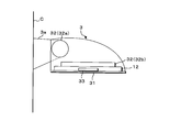
- FIG. 2 is a plan sectional view showing the side mirror 3 in the unfolded state
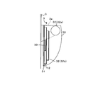
- FIG. 3 is a plan sectional view showing the side mirror 3 in the retracted state
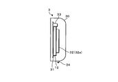
- FIG. 4 is a side sectional view of the side mirror 3.
- the side mirror 3 is, for example, a movable door mirror that is rotatably supported with respect to the vehicle C.
- the side mirror 3 includes a support portion 3a provided on the vehicle body near the left and right side doors, and a streamlined case 30 that is rotatably supported with respect to the support portion 3a.
- a half mirror 31 a side mirror display unit 12, a side mirror drive unit 32, an illuminance sensor 33, a warning unit 34, and the like are accommodated.
- the side mirror drive unit 32 is configured to adjust the angles of the mirror storage drive unit 32a to be stored and unfolded and the mirror surface of the half mirror 31 in the horizontal direction and the elevation direction by rotating the housing 30 of the side mirror 3.
- a mirror angle adjustment unit 32b 2
- the state in which the mirror surface of the half mirror 31 faces rearward is the unfolded state
- the state in which the mirror surface of the half mirror 31 faces the side portion of the vehicle C as shown in FIG. 3 is the retracted state.
- the half mirror 31 is supported by the mirror angle adjustment unit 32b with the mirror surface facing outward from the opening of the housing 30.
- the mirror angle adjustment unit 32b includes a left / right rotation mechanism that rotates the mirror surface of the half mirror 31 in the left / right direction, an elevation rotation mechanism that rotates the mirror surface in the elevation direction, and a motor that drives each mechanism.
- the mirror storage drive unit 32 a has a motor that rotates the housing 30.
- the side mirror display unit 12 is arranged on the back side of the half mirror 31 so that the display surface faces outside through the half mirror 31.
- the side mirror display unit 12 is a self-luminous display panel such as a liquid crystal panel or an organic panel. Accordingly, when the side mirror display unit 12 is not displaying, the half mirror 31 functions as a normal mirror.
- the illuminance sensor 33 is disposed on the back side of the half mirror 31, detects the illuminance of external light transmitted through the half mirror 31, and outputs an illuminance signal corresponding to the detected illuminance to the display control device 11.
- the warning unit 34 is a speaker or a light emitting element that issues a warning by sound or light, and the warning operation is controlled by the display control device 11.
- a plurality of light emitting elements may be provided at appropriate locations around the half mirror 31.
- the mirror turn lamp 35 may be used as the warning unit 34.
- FIG. 5 is a block diagram illustrating a configuration example of the vehicle information display system according to the first embodiment of the present invention.
- the display control device 11 includes a control unit 11 a that controls the operation of each component of the display control device 11.
- the control unit 11a is a microcomputer having, for example, one or a plurality of CPUs (Central Processing Unit), a multi-core CPU, a ROM (Read Only Memory), a RAM (Random Access Memory), a timing unit, and the like.
- the control unit 11a includes a storage unit 11b, a transmission unit 11c, a reception unit 11d, an input unit 11e, and an output unit 11f.
- the control part 11a controls the operation
- the angle of elevation of the mirror surface of the side mirror 3 is adjusted to an angle that is easy to see from the user A considering external light, and information indicating the state of the vehicle C or misplacement of the portable machine 2 is displayed. Execute the process to display on the mirror surface.
- the control unit 11a executes a process of displaying information indicating that the lighting of the room lamp, the headlamp, etc. is forgotten to be turned off or the portable device 2 is left behind on the mirror surface of the side mirror 3.
- the storage unit 11b is a nonvolatile memory such as an EEPROM (ElectricallyrErasable Programmable ROM) or a flash memory.
- the storage unit 11b controls the operation of each component of the display control device 11 by the control unit 11a, so that when the occupant gets out of the vehicle as described above, the elevation angle of the mirror surface of the side mirror 3 is considered in consideration of outside light.
- a control program for adjusting the angle from A to an easy-to-view angle and executing a process of displaying on the side mirror display unit 12 information indicating the state of the vehicle C not in a predetermined state or misplacement of the portable device 2 is stored.
- the transmission unit 11c is connected to the plurality of LF transmission antennas 4, and transmits various signals for specifying the position of the portable device 2 according to the control of the control unit 11a.
- the plurality of LF transmission antennas 4 are provided, for example, at the driver's seat side pillar, the passenger's seat side pillar, the front part and the rear part in the vehicle.
- the transmission unit 11 c transmits a position detection signal for detecting the position of the portable device 2 from each LF transmission antenna 4 under the control of the control unit 11 a.
- the position detection signal is a signal for specifying the position of the portable device 2 based on whether the portable device 2 has received the position detection signal.
- the position detection signal is, for example, a modulated carrier wave.
- the strength of the position detection signal transmitted from the LF transmitting antenna 4 provided on the driver side pillar is such that the portable device 2 can receive the position detection signal in the vicinity of the door on the driver side, for example, in the range of 2 to 3 m. Strength.
- the strength of the position detection signal transmitted from the LF transmitting antenna 4 provided on the passenger side pillar is such that the portable device 2 outputs the position detection signal in the vicinity of the door on the passenger side, for example in the range of 2 to 3 m. It is strong enough to receive.
- the strength of the position detection signal transmitted from the LF transmission antenna 4 in the vehicle is such that the portable device 2 can receive the position detection signal in the vehicle.
- the portable device 2 includes a portable control unit that controls the operation of each component.
- the portable control unit includes, for example, a portable side receiving unit, a portable side transmitting unit, a portable side storage unit, and an operation unit.
- the portable-side receiving unit is connected to the LF receiving antenna, receives various signals transmitted from the display control device 11 using radio waves in the LF band, and outputs information obtained by reception to the portable control unit.
- the portable side transmission unit is connected to the RF transmission antenna, and transmits various signals using radio waves in the UHF band according to the control of the portable control unit. For example, the portable side transmission unit transmits a response signal when the position detection signal transmitted from the display control device 11 is successfully received and authenticated.
- the operation unit includes an operation button for locking and unlocking the vehicle C door, a confirmation button for notifying that the information displayed on the side mirror 3 has been confirmed, and the portable control unit monitors the operation state of the operation unit. ing.
- the portable control unit is a control signal for controlling unlocking or locking of the vehicle C door, a confirmation signal for notifying that the information displayed on the side mirror 3 has been confirmed, and the like.
- a signal corresponding to is transmitted to the mobile-side transmitter.
- the reception unit 11d is connected to the RF reception antenna 11g, receives various signals transmitted from the portable device 2 using radio waves in the UHF band, and outputs information obtained by reception to the control unit 11a.
- the portable device 2 is configured to transmit a response signal by radio waves in the RF band when the position detection signal is successfully received and authenticated, and the receiving unit 11d is transmitted from the portable device 2.
- a response signal is received.
- the control unit 11a determines whether or not the portable device 2 is in the vehicle depending on the presence / absence of a response signal transmitted from the portable device 2 when a position detection signal is transmitted from each LF transmission antenna 4. It can be determined whether or not it is within a predetermined range of the periphery.
- the input unit 11e includes an ignition switch 51, a getting-off detection switch 52 and a getting-off sensor 53 for detecting the getting-off of the user A who is an occupant, an occupant monitoring device 54 for monitoring the occupant, and various states of the vehicle C.
- a vehicle state detection switch 55, an operation switch 56 for operating the vehicle C, a mirror state detection unit 57 for detecting a deployed state or a retracted state of the side mirror 3, an elevation angle detection unit 58, an illuminance sensor 33, and the like are connected. ing.
- An ignition switch signal corresponding to the operation state of the ignition switch 51 is input to the input unit 11e, and the control unit 11a recognizes the operation state of the ignition switch 51 based on the ignition switch signal input to the input unit 11e. be able to.
- the getting-off detection switch 52 is, for example, a buckle switch for detecting attachment / detachment of a seat belt, an unlocking / unlocking detection switch for detecting a door unlocking / unlocking state, an opening / closing detection switch for turning on / off according to the door opening / closing state.
- the open / close detection switch is, for example, a courtesy switch.
- the input unit 11e receives an attachment / detachment state signal corresponding to the attachment / detachment state of the seat belt, a lock / unlock state signal indicating the door lock / unlock state of the vehicle C, and a door open / close signal corresponding to the door open / close state.
- the part 11a can recognize the attachment / detachment state of the seat belt, the door locking / unlocking state, and the door opening / closing state based on various signals input to the input unit 11e.
- the getting-off sensor 53 is, for example, a pressure-sensitive sensor that is provided on the seat surface of the seat and outputs a signal according to the load of the seated passenger.
- a seating signal corresponding to the occupant's seating state is input to the input unit 11e, and the control unit 11a can recognize the presence or absence of seating based on the seating signal input to the input unit 11e.
- the control unit 11a can determine whether the occupant is getting off based on the signals from the getting-off detection switch 52 and the getting-off sensor 53. For example, when the seat belt is removed and the buckle switch is in the off state, the door is unlocked and in the open state, and the user A is not in the seated state, the control unit 11a is in the state of getting off the vehicle. It is determined that
- the occupant monitoring device 54 includes, for example, an imaging device provided in the vehicle, and the imaging device determines the state of the occupant based on the image data obtained by imaging, and outputs the determination result to the control unit 11a.
- the occupant monitoring device 54 can determine the presence / absence of an occupant, getting on / off, and the like. Based on the determination result output from the occupant monitoring device 54, the control unit 11a can detect the passenger getting off more accurately.
- the vehicle state detection switch 55 is a switch that outputs a signal according to the position of the shift lever, a switch that outputs a signal according to the parking brake state, a switch that detects the open / closed state of the window of the vehicle C, and the like.
- a signal corresponding to the state of each switch is input to the input unit 11e, and the control unit 11a, based on the signal input to the input unit 11e, the position of the shift lever, the state of the parking brake, the opening / closing state of the window For example, the state of the vehicle C can be detected.
- the operation switch 56 is a switch for operating electrical components, such as a switch for turning on / off a room light, a switch for turning on / off a lighting device, and a switch for turning on / off a headlamp.
- the control unit 11a can recognize the state of the operation switch 56, that is, the state related to the operation of the vehicle C, via the input unit 11e.
- the input unit 11e receives a mirror state signal indicating the storage state in which the side mirror 3 is closed or the unfolded state in which the side mirror 3 is unfolded, and the control unit 11a receives the mirror input to the input unit 11e. Based on the state signal, it can be recognized whether or not the side mirror 3 is in the stored state.
- the mirror state detection unit 57 is, for example, a switch for expanding or storing the side mirror 3.
- an elevation angle signal indicating the elevation angle of the mirror surface of the half mirror 31 is input to the input unit 11e, and the control unit 11a receives the elevation angle signal input to the input unit 11e.
- the elevation angle of the mirror surface can be recognized.
- the illuminance signal output from the illuminance sensor 33 is input to the input unit 11e, and the control unit 11a receives the sun incident on the mirror surface of the side mirror 3 by the illuminance signal input to the input unit 11e.
- the intensity of external light such as light can be recognized.
- the output unit 11f is connected to the side mirror display unit 12, the side mirror driving unit 32, the warning unit 34, the mirror turn lamp 35, and the locking / unlocking device 6 for locking and unlocking the door.
- the control part 11a outputs the video signal which shows the information which shows the state of the vehicle C or the misplacement of the portable device 2 to the side mirror display part 12 via the output part 11f, thereby the information relating to the state of the vehicle C on the mirror surface. Is displayed. Further, the control unit 11a outputs a deployment signal for instructing the deployment of the side mirror 3 and a storage signal for instructing the storage to the mirror storage drive unit 32a of the side mirror drive unit 32 via the output unit 11f.
- the mirror 3 can be expanded or stored.
- control part 11a can adjust the elevation angle of a mirror surface by outputting an angle adjustment signal to the mirror angle adjustment part 32b via the output part 11f. Furthermore, the control unit 11a can issue an alarm by outputting a warning control signal to the warning unit 34 via the output unit 11f. Further, the control unit 11a can turn on the mirror turn lamp 35 by outputting a lighting signal to the mirror turn lamp 35 via the output unit 11f.
- the locking / unlocking device 6 includes a known locking / unlocking mechanism that locks / unlocks the door of the vehicle C and an actuator that drives the locking / unlocking mechanism, and an actuator is connected to the output unit 11f.
- control unit 11a When the control unit 11a detects that the door switch is operated and detects a regular portable device 2 within a predetermined range outside the vehicle, the control unit 11a outputs a locking signal or an unlocking signal from the output unit 11f, thereby Is operated to lock or unlock the door.
- step S11 the control unit 11a of the display control device 11 performs the following processing.
- the controller 11a detects the on / off state of the getting-off detection switch 52 (step S11), and acquires the detection result of the getting-off sensor 53 (step S12). Then, based on the on / off state of the getting-off detection switch 52 and the detection result of the getting-off sensor 53, it is determined whether or not the passenger has got off (step S13). When it determines with having not got off (step S13: NO), the control part 11a returns a process to step S11, and continues monitoring of a passenger
- the control unit 11a detects the state of the vehicle C using the vehicle state detection switch 55 and the operation switch 56 (step S14), and the state of the vehicle C is predetermined. It is determined whether it is in a state (step S15).
- the predetermined state is, for example, a state in which an indoor lamp, a lighting device, or a headlamp is turned off, a window is closed, a shift lever is in a parking position, or a parking brake is applied.
- the control part 11a detects the position of the portable device 2 (step S16), and determines whether the portable device 2 is in the vehicle.
- Step S17 the control unit 11a causes the transmission unit 11c to sequentially transmit a position detection signal from the LF transmission antenna 4 in the vehicle, and receives a response signal transmitted from the portable device 2 that has received the position detection signal.
- the reachable range of the position detection signal that is, the range in which the portable device 2 can receive and demodulate the position detection signal is around 2 to 3 m around each LF transmission antenna 4.
- the transmission intensity of the position detection signal is set so that the range in which the position detection signal transmitted from the LF transmission antenna 4 in the vehicle can be received and demodulated is the range of the passenger compartment.
- the portable device 2 When the portable device 2 is in the vehicle, the portable device 2 can receive a position detection signal and transmits a response signal.
- the control unit 11a determines whether the portable device 2 is in the vehicle based on the presence / absence of a response signal to the transmitted position detection signal.
- step S17 NO
- the control part 11a is in the state by which the side mirror 3 was expand
- step S18 the control unit 11a outputs a storage signal for instructing storage of the side mirror 3 when the predetermined storage condition is satisfied, to the output unit 11f.
- the side mirror 3 is stored by outputting to the mirror storage drive unit 32a via (step S19).
- the mirror storage condition is, for example, that the ignition switch 51 is off or the door is locked.
- step S19 When the process of step S19 is completed, or when it is determined in step S18 that the side mirror 3 is not in the deployed state (step S18: NO), the control unit 11a detects the position of the portable device 2 (step S20). ), It is determined whether or not the portable device 2 is outside a predetermined range outside the vehicle (step S21). When it determines with the portable device 2 being outside a predetermined range (step S21: YES), the control part 11a finishes a process. When it determines with the portable device 2 being in the predetermined range (step S21: NO), the control part 11a returns a process to step S14.
- step S15 When it is determined in step S15 that the state of the vehicle C is not in the predetermined state (step S15: NO), or when it is determined in step S17 that the portable device 2 is in the vehicle (step S17: YES), the control unit 11a Based on the mirror state signal input to the input unit 11e, it is determined whether or not the side mirror 3 is in the stored state (step S22). When it is determined that the side mirror 3 is in the stored state (step S22: YES), the control unit 11a outputs a deployment signal instructing the deployment of the side mirror 3 to the mirror storage drive unit 32a via the output unit 11f. As a result, the side mirror 3 is unfolded (step S23), and the process of step S20 is executed.
- the mirror turn lamp 35 may be lighted. That is, when the state of the vehicle C is not in a predetermined state or the portable device 2 is in the vehicle, the controller 11a is configured to turn on the mirror turn lamp 35 by outputting a lighting signal to the mirror turn lamp 35. May be.
- the mirror turn lamp 35 blinks when the side mirror 3 is expanded or stored as a normal operation, and the mirror turn lamp when there is a state of the vehicle C or misplacement of the portable device 2 A configuration different from the mode of lighting 35 is preferable. The user A can easily recognize from the lighting state of the mirror turn lamp 35 that the vehicle C is not in a predetermined state, and that some information such as misplacement of the portable device 2 is displayed on the side mirror 3. Can do.
- step S22 If it is determined in step S22 that the mirror is in the unfolded state (step S22: NO), the controller 11a detects the elevation angle of the mirror surface of the side mirror 3 by the elevation angle detection unit 58 (step S24). The detected elevation angle is stored in the storage unit 11b (step S25).
- control unit 11a adjusts the elevation angle of the mirror surface of the side mirror 3 (step S26).
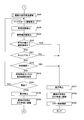
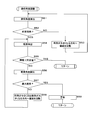
- FIG. 8 is a flowchart showing a processing procedure for adjusting the elevation angle of the mirror surface of the side mirror 3
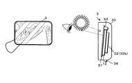
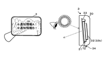
- FIGS. 9A and 9B are conceptual diagrams showing a method for adjusting the elevation angle of the side mirror 3
- FIG. 10 a conceptual diagram showing a warning method. is there.
- the control unit 11a executes the following process. First, the controller 11a detects the elevation angle of the mirror surface of the side mirror 3 by the elevation angle detection unit 58 (step S51), and determines whether the elevation angle is a predetermined angle (step S52).
- the predetermined elevation angle is an angle formed by the line of sight of the user A near the door outside the vehicle with respect to the horizontal plane. In the case of a sports type vehicle C having a low vehicle height, the predetermined elevation angle is relatively large, and in the case of a wagon type vehicle C, the predetermined elevation angle is relatively small.
- the predetermined elevation angle is stored in advance in the storage unit 11b.
- step S52 When it is determined that the elevation angle is not the predetermined angle (step S52: NO), the control unit 11a outputs an angle adjustment signal to the mirror angle adjustment unit 32b, thereby increasing the mirror surface elevation angle to the half mirror 31. Is rotated (step S53), and the process returns to step S51.
- the elevation angle of the side mirror 3 becomes an angle at which the mirror surface can be easily seen from the user A near the door outside the vehicle.
- the elevation angle is an optimum angle in a situation where the influence of outside light such as sunlight is not considered, and the elevation angle is adjusted in consideration of the influence of outside light in the following processing.
- the control part 11a detects the illumination intensity in the side mirror 3 with the illumination intensity sensor 33 (step S54), and was detected. It is determined whether or not the illuminance is less than a predetermined value (step S55).
- the illuminance indicates the possibility that external light such as sunlight reflected by the mirror surface of the side mirror 3 is reflected on the face of the user A. For example, as illustrated in FIG. 9A, when the incident angle of sunlight with respect to the mirror surface is high, there is a high possibility that the sunlight is reflected to the face of the user A who is looking at the side mirror 3 from obliquely above.
- the illuminance detected by the illuminance sensor 33 increases. Conversely, as shown in FIG. 9B, when the incident angle of sunlight with respect to the mirror surface is low, there is a low possibility that the sunlight will be reflected on the face of the user A who is looking at the side mirror 3 from obliquely above. In this case, the illuminance detected by the illuminance sensor 33 is reduced.
- step S55: YES When it is determined that the illuminance is less than the predetermined value (step S55: YES), the control unit 11a finishes the process related to the elevation angle adjustment. That is, the elevation angle of the mirror surface of the side mirror 3 is determined to be an optimum angle with a low possibility of external light being reflected on the face of the user A, and the elevation / elevation angle adjustment processing is ended.
- step S55 the control part 11a detects the elevation angle of the mirror surface of the side mirror 3 in the elevation angle detection part 58 (step S56), and an elevation angle is set. It is determined whether it is a predetermined maximum depression angle (step S57).
- step S57 NO
- the control unit 11a When it is determined that the elevation angle of the mirror surface is not the predetermined maximum depression angle (step S57: NO), the control unit 11a outputs an angle adjustment signal to the mirror angle adjustment unit 32b, thereby reducing the elevation angle of the mirror surface or the depression angle.
- the half mirror 31 is rotated in the increasing direction (step S58), and the process returns to step S54.
- the control unit 11a issues an alarm at the warning unit 34 (step S59) and ends the process related to the elevation angle adjustment.
- the warning unit 34 emits a warning sound B or a warning light L as shown in FIG.
- the control unit 11a When the elevation / elevation angle adjustment in step S26 is completed, the control unit 11a outputs a video signal for displaying information indicating the state of the vehicle C detected in step S14 and the position of the portable device 2 detected in step S16. By outputting to the side mirror display part 12 at 11f, the information regarding the state of the vehicle C or misplacement of the portable device 2 is displayed on the left and right side mirror display parts 12 (step S27).
- FIG. 11 is a schematic diagram showing a situation in which the information of the vehicle C is displayed on the mirror surface of the side mirror 3.
- a predetermined image and characters may be displayed on the side mirror display unit 12 when the portable device 2 is left behind.
- the side mirror display part 12 displays that the vehicle C is not in a predetermined state with a character.
- control unit 11a detects the state of the vehicle C using the vehicle state detection switch 55 and the operation switch 56 (step S28), and detects the position of the portable device 2 (step S29). Then, the control unit 11a determines whether or not the state of the vehicle C is in a predetermined state and the portable device 2 is outside the vehicle (step S30).
- step S30: NO When it is determined that the state of the vehicle C is not in the predetermined state or the portable device 2 is in the vehicle (step S30: NO), the control unit 11a displays information on the side mirror display unit 12 using the time measuring unit. Then, it is determined whether or not a predetermined time has elapsed (step S31). When it determines with not being in a timeout state (step S31: NO), the control part 11a determines whether the content confirmation was performed by the user A (step S32). For example, the user A can notify the display control device 11 that the information displayed on the side mirror 3 has been confirmed by operating the confirmation button of the portable device 2. The control unit 11a determines that the content confirmation has been performed when the reception unit 11d receives a confirmation signal transmitted from the portable device 2 in response to the operation of the confirmation button of the portable device 2.
- step S32 determines with content confirmation not being performed
- step S33 determines whether the user A was seated again
- step S34 determines whether the user A was seated again
- step S34 determines with not sitting
- step S34: NO the control part 11a returns a process to step S27.
- step S34: YES the control unit 11a stops the side mirror display unit 12 (step S35).
- control unit 11a outputs an angle adjustment signal to the mirror angle adjustment unit 32b via the output unit 11f, whereby the elevation angle of the mirror surface of the side mirror 3 substantially matches the elevation angle stored in the storage unit 11b.
- the half mirror 31 is rotated in a direction to decrease the elevation angle (step S36), and the process returns to step S11.
- the control unit 11a detects the elevation angle by the elevation angle detection unit 58 while rotating the half mirror 31, and the detected elevation angle is substantially equal to the elevation angle stored in the storage unit 11b. If they match, the output of the angle adjustment signal may be stopped.
- step S30 If it is determined in step S30 that the state of the vehicle C is in a predetermined state and the portable device 2 is outside the vehicle (step S30: YES), if it is determined in step S31 that it is in a time-out state (step S31: YES), Or when it determines with the content confirmation having been performed in step S32 (step S32: YES), the control part 11a stops the side mirror display part 12 (step S37).
- control unit 11a outputs an angle adjustment signal to the mirror angle adjustment unit 32b via the output unit 11f, so that the mirror elevation angle of the side mirror 3 substantially matches the elevation angle stored in the storage unit 11b.
- the half mirror 31 is rotated in the direction in which the elevation angle becomes smaller (step S38).
- the control part 11a stores the side mirror 3 by outputting the storage signal which instruct
- the elevation angle of the mirror surface of the half mirror 31 is automatically set to an angle that is easy to see from the user A outside the vehicle. It is possible to adjust, and the visibility of the user A can be ensured. Specifically, the visibility of the user A with respect to the side mirror 3 can be ensured by rotating the half mirror 31 until the elevation angle becomes a predetermined elevation angle.
- the vehicle information display device 1 displays information on the mirror surface of the side mirror 3, the angle at which the mirror surface is easy to see from the user A outside the vehicle and outside light such as sunlight is not reflected to the user A. Therefore, the visibility of the user A can be ensured.
- the user A may not be aware of the information displayed on the side mirror 3 if the illuminance at the side mirror 3 is greater than or equal to a predetermined level.
- the unit 34 can inform the side mirror 3 that information is displayed by issuing a warning.
- the elevation angle of the mirror surface of the side mirror 3 can be returned to the original elevation angle that is easy to see from the user A in the vehicle.
- information indicating the state of the vehicle C can be displayed on the mirror surface of the side mirror 3 when the vehicle gets off.
- the side mirror 3 information indicating forgetting to turn off lighting such as room lights, lighting equipment, and headlamps when getting off the vehicle.
- information indicating forgetting to close the window, forgetting to apply the parking brake, forgetting to operate the shift lever to the parking position at the time of getting off can be displayed on the mirror surface of the side mirror 3.
- information indicating that the portable device 2 has been left behind in the vehicle can be displayed on the mirror surface of the side mirror 3.
- the side mirror 3 can be unfolded and information can be displayed on the mirror surface of the side mirror 3.
- the display of information on the side mirror display unit 12 is stopped. That is, the display of information on the side mirror 3 disappears. Therefore, the user A getting off can recognize that the problem has been resolved by confirming that the information displayed on the mirror surface of the side mirror 3 has disappeared.
- the information displayed on the side mirror 3 can be arbitrarily deleted by operating the confirmation button of the portable device 2.
- information indicating that the state of the vehicle C is not in a predetermined state or that the portable device 2 is left behind is displayed on the side mirror 3 using the self-luminous side mirror display unit 12 disposed on the back surface of the half mirror 31. Can be displayed superimposed on the mirror surface.
- the transmission unit 11c sequentially transmits position detection signals transmitted from the LF transmission antennas 4, for example, unmodulated waves.
- the portable device 2 measures the received signal strength of each position detection signal and transmits a response signal including the received signal strength obtained by the measurement to the display control device 11.
- the display control device 11 receives the response signal transmitted from the portable device 2 and calculates the position of the portable device 2 with respect to the vehicle C based on the received signal strength included in the response signal. Since the received signal strength corresponds to the position of each LF transmission antenna 4 and the portable device 2 and the position of the LF transmission antenna 4 with respect to the vehicle C is known, the position of the portable device 2 with respect to the vehicle C is obtained. Can do.
- the information is displayed only on the side mirror display unit 12 on the side where the portable device 2 is detected. You may comprise as follows.
- the display panel has been described on the back of the half mirror 31 as the side mirror display unit 12 that displays information on the mirror surface.
- the side mirror display unit 12 is an electronic mirror that displays an image behind the vehicle. There may be.
- the light emission intensity related to the display of the side mirror display unit 12 when the light emission intensity related to the display of the side mirror display unit 12 can be increased or decreased, the light emission intensity related to the display of the side mirror display unit 12 is increased when the illuminance detected by the illuminance sensor 33 is a predetermined value or more. You may control so that it may increase.
- the vehicle information display system according to the second embodiment is different from the first embodiment in that the display control device 111 and the side mirror display unit 12 are modularized so as to be housed in the housing 30 of the side mirror 3.
- the above differences will be mainly described, and other configurations and operational effects are the same as those of the first embodiment. Therefore, corresponding portions are denoted by the same reference numerals, and detailed description thereof is omitted.
- FIG. 12 is a block diagram showing a configuration example of the vehicle information display system according to the second embodiment of the present invention
- FIG. 13 shows a configuration example of the vehicle information display apparatus 101 according to the second embodiment of the present invention. It is a block diagram.
- the positions of the vehicle information display device 101, the side mirror drive control unit 134, the side mirror drive unit 32, and the portable device 2 housed in the casing 30 of the side mirror 3 are determined.
- An in-vehicle device 7 that detects and locks and unlocks the door and a portable device 2 are provided.
- the in-vehicle device 7 is connected to the vehicle information display device 101 via an in-vehicle communication line that conforms to a communication protocol such as CAN, FlexRay, or LIN.
- the in-vehicle device 7 has the same configuration as the display control device 111 according to the first embodiment, and executes processing for detecting the state of the vehicle C, processing for detecting the portable device 2, processing for locking and unlocking the door, and the like.
- In-vehicle device 7 receives information from vehicle information display device 101 such as the position of portable device 2, information related to getting off, information indicating the state of vehicle C, the storage state of side mirror 3, and the like. Transmit to the display device 101.
- the vehicle information display device 101 includes a side mirror display unit 12 and a display control device 111. Similar to the first embodiment, the display control device 111 includes a control unit 11a, a storage unit 11b, an input unit 11e, an output unit 11f, and a communication unit 11h. However, the transmission unit 11c and the reception unit 11d for detecting the position of the portable device 2 are not provided, and the display control device 111 determines whether or not the portable device 2 is in the vehicle and the portable device 2 is outside a predetermined range outside the vehicle. Information indicating whether or not there is obtained from the in-vehicle device 7.
- the communication unit 11h is a communication device that performs communication according to a predetermined communication protocol such as CAN, FlexRay, or LIN, and is connected to the in-vehicle device 7 via an in-vehicle communication line.
- the control part 11a is the information transmitted from the vehicle equipment 7 in the communication part 11h, that is, the position of the portable device 2, the information related to the getting-off state, the information indicating the state of the vehicle C, the storage state of the side mirror 3, the half mirror Information such as 31 elevation angles is acquired.
- the input / output unit 11e is connected to the elevation angle detection unit 58 and the illuminance sensor 33.
- the controller 11 a can detect the elevation angle of the mirror surface of the side mirror 3 with the elevation angle detection unit 58, and can detect the illuminance at the side mirror 3 with the illuminance sensor 33. .
- a side mirror display unit 12, a side mirror drive control unit 134, and a warning unit 34 are connected to the output unit 11f.
- the control unit 11a displays information on the mirror surface of the side mirror 3 by outputting a video signal from the output unit 11f to the side mirror display unit 12.
- the control unit 11a outputs the expansion signal and the storage signal from the output unit 11f to the side mirror drive control unit 134, thereby causing the side mirror 3 to expand and store.
- the control unit 11a adjusts the elevation angle of the half mirror 31 by outputting an angle adjustment signal from the output unit 11f to the side mirror drive control unit 134.
- the side mirror drive control unit 134 drives the side mirror drive unit 32 in accordance with each signal output from the display control device 111. Furthermore, the control unit 11 a can issue a warning by outputting a warning signal to the warning unit 34.
- the control unit 11a When the occupant gets out of the vehicle C, the control unit 11a performs the same processing procedure as that of the first embodiment. If the state of the vehicle C is not in the predetermined state, or if the portable device 2 is in the vehicle, the state of the vehicle C, the portable device 2 The side mirror display unit 12 displays that the vehicle is in the vehicle.
- the vehicle information display device 101 when displaying information on the mirror surface of the side mirror 3, as in the first embodiment, it is easy to see the elevation angle of the mirror surface from the user A outside the vehicle, and the sunlight. Therefore, the visibility of the user A can be ensured.
- the vehicle information display system according to the present invention can be configured easily.
Landscapes
- Engineering & Computer Science (AREA)
- Multimedia (AREA)
- Mechanical Engineering (AREA)
- Rear-View Mirror Devices That Are Mounted On The Exterior Of The Vehicle (AREA)
- Fittings On The Vehicle Exterior For Carrying Loads, And Devices For Holding Or Mounting Articles (AREA)
Abstract
車両用情報表示装置は、乗員の乗車時又は降車時に、車両に設けられたサイドミラーの鏡面に情報を表示する表示部と、サイドミラーにおける照度を検出すると、表示部が情報を表示する場合、照度センサにて検出された照度及び所定値を比較する比較部と、サイドミラーの鏡面を俯仰方向へ回動させるミラー角度調整部へ、サイドミラーの鏡面の回動を指示する角度調整信号を出力する出力部と、照度センサにて検出された照度が所定値以上である場合、俯角が大きくなる方向への鏡面の回動を指示する角度調整信号を出力部に出力させる制御部とを備える。
Description
本発明は、車両用情報表示装置に関する。
本出願は、2016年8月30日出願の日本出願第2016-168380号に基づく優先権を主張し、前記日本出願に記載された全ての記載内容を援用するものである。
本出願は、2016年8月30日出願の日本出願第2016-168380号に基づく優先権を主張し、前記日本出願に記載された全ての記載内容を援用するものである。
車内のインスツルメントパネル又はディスプレイには、車両の状態、例えばヘッドランプ、灯器等の点灯状態、パーキングブレーキの操作状態等を表示する各種警告灯が設けられている。乗員であるユーザは、インスツルメントパネルの表示から、車両の状態を確認することができる。
一方、車両走行中に、車両周辺の死角を走行する車両、歩行者等を検出し、サイドミラーに警告表示を行う車両用情報表示装置がある(例えば、特許文献1)。
一方、車両走行中に、車両周辺の死角を走行する車両、歩行者等を検出し、サイドミラーに警告表示を行う車両用情報表示装置がある(例えば、特許文献1)。
本態様に係る車両用情報表示装置は、乗員の乗車時又は降車時に、車両に設けられたサイドミラーの鏡面に情報を表示する表示部と、前記サイドミラーにおける照度を検出する照度センサと、前記表示部が情報を表示する場合、前記照度センサにて検出された照度及び所定値を比較する比較部と、前記サイドミラーの鏡面を俯仰方向へ回動させるミラー角度調整部へ、前記サイドミラーの鏡面の回動を指示する角度調整信号を出力する出力部と、前記照度センサにて検出された照度が所定値以上である場合、仰角が小さく又は俯角が大きくなる方向への前記鏡面の回動を指示する角度調整信号を前記出力部に出力させる制御部とを備える。
なお、本願は、このような特徴的な処理部を備える車両用情報表示装置として実現することができるだけでなく、かかる特徴的な処理をステップとする車両用情報表示方法として実現したり、かかるステップをコンピュータに実行させるためのプログラムとして実現したりすることができる。また、車両用情報表示装置の一部又は全部を実現する半導体集積回路として実現したり、車両用情報表示装置を含むその他のシステムとして実現したりすることができる。
[本開示が解決しようとする課題]
乗車時又は降車時においては、車内のインスツルメントパネル又はディスプレイに表示したとしても、車外のユーザからは、車内の警告灯、ディスプレイの表示を視認し難く、必要な情報を見落とすおそれがあった。また、サイドミラーに情報を表示することによって、必要な情報をより効果的にユーザに通知することができるものの、サイドミラーの俯仰角度によっては、太陽光等の外光がユーザの顔に反射され、鏡面に表示された情報が視認し辛くなることがある。
乗車時又は降車時においては、車内のインスツルメントパネル又はディスプレイに表示したとしても、車外のユーザからは、車内の警告灯、ディスプレイの表示を視認し難く、必要な情報を見落とすおそれがあった。また、サイドミラーに情報を表示することによって、必要な情報をより効果的にユーザに通知することができるものの、サイドミラーの俯仰角度によっては、太陽光等の外光がユーザの顔に反射され、鏡面に表示された情報が視認し辛くなることがある。
本開示の目的は、乗車時又は降車時にサイドミラーの鏡面に情報を表示する際、サイドミラーの鏡面の俯仰角度を、車外にいるユーザから見やすい角度に自動調整することによって、視認性を確保することができ、より効果的に車外のユーザに情報を通知することができる車両用情報表示装置を提供することにある。
[本開示の効果]
本開示によれば、乗車時又は降車時にサイドミラーの鏡面に情報を表示する際、サイドミラーの鏡面の俯仰角度を、車外にいるユーザから見やすい角度に自動調整することによって、視認性を確保することができ、より効果的に車外のユーザに情報を通知することができる車両用情報表示装置を提供することが可能になる。
本開示によれば、乗車時又は降車時にサイドミラーの鏡面に情報を表示する際、サイドミラーの鏡面の俯仰角度を、車外にいるユーザから見やすい角度に自動調整することによって、視認性を確保することができ、より効果的に車外のユーザに情報を通知することができる車両用情報表示装置を提供することが可能になる。
[本願発明の実施形態の説明]
最初に本発明の実施態様を列記して説明する。また、以下に記載する実施形態の少なくとも一部を任意に組み合わせてもよい。
最初に本発明の実施態様を列記して説明する。また、以下に記載する実施形態の少なくとも一部を任意に組み合わせてもよい。
(1)本態様に係る車両用情報表示装置は、乗員の乗車時又は降車時に、車両に設けられたサイドミラーの鏡面に情報を表示する表示部と、前記サイドミラーにおける照度を検出する照度センサと、前記表示部が情報を表示する場合、前記照度センサにて検出された照度及び所定値を比較する比較部と、前記サイドミラーの鏡面を俯仰方向へ回動させるミラー角度調整部へ、前記サイドミラーの鏡面の回動を指示する角度調整信号を出力する出力部と、前記照度センサにて検出された照度が所定値以上である場合、仰角が小さく又は俯角が大きくなる方向への前記鏡面の回動を指示する角度調整信号を前記出力部に出力させる制御部とを備える。
本態様にあっては、乗車時又は降車時に表示部が情報をサイドミラーの鏡面に表示する際、サイドミラーにおける照度が所定値以上である場合、制御部は角度調整信号を出力部からミラー角度調整部へ出力することによって、仰角が小さく又は俯角が大きくなる方向へ鏡面を回動させる。従って、鏡面の俯仰角度を、太陽光等の外光がユーザへ反射されない角度に自動調整することができ、ユーザの視認性を確保することができる(図9A及び図9B参照)。
(2)前記制御部は、前記表示部が情報を表示する場合、前記照度センサにて検出された照度が所定値未満の範囲で、仰角が大きくなる方向への前記鏡面の回動を指示する角度調整信号を前記出力部に出力させる構成が好ましい。
本態様にあっては、サイドミラーにおける照度が所定値未満の範囲で、俯角が大きくなる方向へサイドミラーの鏡面を回動させる。従って、鏡面の俯仰角度を、車外にいるユーザから見やすく、かつ太陽光等の外光がユーザへ反射されない角度に自動調整することができ、ユーザの視認性を確保することができる。
(3)前記サイドミラーの鏡面の俯仰角度を検出する俯仰角度検出部と、該俯仰角度検出部にて検出される角度が、前記鏡面の俯仰角度が所定の最大俯角であり、かつ前記照度センサにて検出された照度が前記所定値以上である場合、警告を発する警告部とを備える構成が好ましい。
本態様にあっては、サイドミラーの鏡面の俯角が最大俯角になっても、サイドミラーにおける照度が所定以上である場合、ユーザがサイドミラーに表示された情報に気が付かない可能性がある。そこで、当該状態にある場合、警告部は警告を発することによって、サイドミラーに情報が表示されていることを知らせることができる。
(4)前記サイドミラーの鏡面の俯仰角度を検出する俯仰角度検出部と、前記鏡面を回動させる前に、前記俯仰角度検出部にて検出された前記サイドミラーの鏡面の俯仰角度を記憶する記憶部とを備え、前記制御部は、前記表示部が情報の表示を停止する場合、前記俯仰角度検出部にて検出される俯仰角度が、前記記憶部が記憶する俯仰角度に一致するまで、前記鏡面の回動を指示する角度調整信号を前記出力部に出力させる構成が好ましい。
本態様にあっては、記憶部は、鏡面を俯仰方向へ回動させる前に、俯仰角度を記憶する。表示部が情報の表示を停止する場合、制御部は、鏡面の俯仰角度が、記憶部の記憶する俯仰角度に一致するまで、角度調整信号を出力部からミラー角度調整部へ出力する。従って、サイドミラーへの情報の表示を終えた場合、サイドミラーの鏡面の俯仰角度を、車内にいるユーザから見やすい俯仰角度に戻すことができる。
(5)本態様に係る車両用情報表示装置は、前記車両の状態を検出する車両状態検出部と、該車両状態検出部にて検出した状態が所定状態であるか否かを判定する判定部と、乗員の降車を検出する降車検出部とを備え、前記表示部は、前記降車検出部にて乗員の降車が検出され、前記判定部にて前記所定状態で無いと判定された場合、前記車両状態検出部にて検出された状態を示す情報を、前記サイドミラーの前記鏡面に表示する構成が好ましい。
本態様にあっては、乗員の降車が検出された場合、車両の状態が所定状態で無いとき、当該車両の状態が表示部によってサイドミラーの鏡面に表示される。従って、降車したユーザは、車外から視認し易いサイドミラーの鏡面に表示された情報から、所定状態に無い車両の状態を認知することができる。所定状態は、駐車時にあるべき各種スイッチのオンオフ状態、操作部の操作状態等である。例えば、室内灯を点灯させるスイッチのオンオフ状態、ヘッドランプのオンオフ状態、パーキングブレーキの操作状態、窓の昇降状態等が挙げられる。
このため、ユーザは、降車時に車両が所定状態に無い場合、車両の状態に応じた必要な処置を採ることができる。
このため、ユーザは、降車時に車両が所定状態に無い場合、車両の状態に応じた必要な処置を採ることができる。
(6)車内にある携帯機を検出する携帯機検出部を備え、前記表示部は、前記降車検出部にて乗員の降車が検出され、前記携帯機検出部にて車内にある前記携帯機が検出された場合、前記携帯機が車内にあることを示す情報を、前記車両に設けられたサイドミラーの鏡面に表示する構成が好ましい。
本態様にあっては、乗員の降車が検出された場合、車内にある携帯機が検出された場合、携帯機が車内に残されていることを示す情報が表示部によってサイドミラーの鏡面に表示される。従って、降車したユーザは、車外から視認し易いサイドミラーの鏡面に表示された情報から、携帯機が車内に残されていることを認知することができる。
(7)前記車両の状態は、前記車両に設けられた照明を操作するスイッチのオンオフ状態又は前記車両に設けられた窓の開閉状態を含み、前記所定状態は、前記スイッチがオフ状態又は前記窓が閉状態である構成が好ましい。
本態様にあっては、乗員の降車が検出された場合、車両に設けられた照明を操作するスイッチがオフ状態に無いとき、当該状態が表示部によってサイドミラーの鏡面に表示される。照明は、室内灯、ヘッドランプ、灯器等である。また乗員の降車が検出された場合、窓が閉じた状態に無いとき、当該状態が表示部によってサイドミラーの鏡面に表示される。
(8)前記出力部は、前記表示部が情報を表示する場合、前記サイドミラーを回動させることにより格納及び展開させる駆動部へ、前記サイドミラーの展開を指示する展開信号を出力する構成が好ましい。
本態様にあっては、サイドミラーが格納されている場合であっても、サイドミラーを展開させて、所定状態に無い車両の状態を示す情報を表示することができる。
(9)前記出力部は、前記表示部が情報の表示を停止した場合、前記サイドミラーの格納を指示する格納信号を出力する構成が好ましい。
本態様にあっては、表示部が情報の表示を停止した場合、出力部はサイドミラーの格納を指示する格納信号を出力する。従って、情報の表示が不要になった場合、サイドミラーを格納することができる。
(10)前記表示部は、情報を表示した後、前記判定部にて前記所定状態であると判定された場合、前記情報の表示を停止する構成が好ましい。
本態様にあっては、サイドミラーの鏡面に情報が表示された後、その原因となる状態が解消され、車両の状態が所定状態となった場合、表示部が情報の表示を停止する。
従って、ユーザは、問題が解消したことを視認することができる。
従って、ユーザは、問題が解消したことを視認することができる。
[本発明の実施形態の詳細]
本発明の実施形態に係る車両用情報表示システムの具体例を、以下に図面を参照しつつ説明する。なお、本発明はこれらの例示に限定されるものではなく、請求の範囲によって示され、請求の範囲と均等の意味及び範囲内でのすべての変更が含まれることが意図される。
本発明の実施形態に係る車両用情報表示システムの具体例を、以下に図面を参照しつつ説明する。なお、本発明はこれらの例示に限定されるものではなく、請求の範囲によって示され、請求の範囲と均等の意味及び範囲内でのすべての変更が含まれることが意図される。
(実施形態1)
図1は、本発明の実施形態1に係る車両用情報表示システムの一構成例を示す模式図である。本実施形態1に係る車両用情報表示システムは、車両Cの左右両側ドア付近に設けられたサイドミラー3の鏡面に情報を表示する車両用情報表示装置1と、ユーザAが所持する携帯機2とを備える。
図1は、本発明の実施形態1に係る車両用情報表示システムの一構成例を示す模式図である。本実施形態1に係る車両用情報表示システムは、車両Cの左右両側ドア付近に設けられたサイドミラー3の鏡面に情報を表示する車両用情報表示装置1と、ユーザAが所持する携帯機2とを備える。
車両用情報表示装置1は、サイドミラー3の鏡面に情報を表示するサイドミラー表示部12と、当該サイドミラー表示部12の動作を制御する表示制御装置11とを備える。表示制御装置11は、乗員の降車を検出した場合、車両Cが所定状態に無いとき、サイドミラー3の鏡面の俯仰角度を、外光を考慮したユーザAから見やすい角度に調整し、当該車両Cの状態を示す情報をサイドミラー表示部12に表示させる。所定状態は、例えば、室内灯、灯火器、ヘッドランプがオフ状態、窓が閉状態、シフトレバーがパーキングポジションにある状態、及びパーキングブレーキがかかっている状態の全ての各状態を満たした状態である。
また、表示制御装置11は、ユーザAが所持する携帯機2との間で無線通信を行い、携帯機2の位置を検出する機能を有する。表示制御装置11は、乗員の降車を検出した場合、携帯機2が車内にあるとき、携帯機2の置き忘れを示す情報をサイドミラー表示部12に表示させる。
また、表示制御装置11は、ユーザAが所持する携帯機2との間で無線通信を行い、携帯機2の位置を検出する機能を有する。表示制御装置11は、乗員の降車を検出した場合、携帯機2が車内にあるとき、携帯機2の置き忘れを示す情報をサイドミラー表示部12に表示させる。
図2は、展開状態にあるサイドミラー3を示す平断面図、図3は、格納状態にあるサイドミラー3を示す平断面図、図4はサイドミラー3の側断面図である。サイドミラー3は、例えば、車両Cに対して回動可能に支持された可動式のドアミラーである。サイドミラー3は、左右両側ドア付近の車体にそれぞれ設けられた支持部3aと、当該支持部3aに対して回動可能に支持された流線型の筐体30とを有する。筐体30の内部には、ハーフミラー31、サイドミラー表示部12、サイドミラー駆動部32、照度センサ33及び警告部34等が収容されている。
サイドミラー駆動部32は、サイドミラー3の筐体30を回動させることによって、格納及び展開させるミラー格納駆動部32aと、ハーフミラー31の鏡面の左右方向及び俯仰方向の角度を調整するためのミラー角度調整部32bとを備える。なお、図2に示すように、ハーフミラー31の鏡面が後方を向いた状態が展開状態、図3に示すようにハーフミラー31の鏡面が車両Cの側部を向いた状態が格納状態である。
ハーフミラー31は筐体30の開口部から鏡面を外側に向けた状態でミラー角度調整部32bにて支持されている。ミラー角度調整部32bは、ハーフミラー31の鏡面を左右方向へ回動させる左右回動機構と、鏡面を俯仰方向へ回動させる俯仰回転機構と、各機構を駆動させるモータとを有する。
ミラー格納駆動部32aは、筐体30を回動させるモータを有する。
サイドミラー表示部12は、表示面がハーフミラー31を介して外側を向くように、ハーフミラー31の背面側に配されている。サイドミラー表示部12は、例えば、液晶パネル、有機パネル等、自発光型の表示パネルである。従って、サイドミラー表示部12が表示を行っていない場合、ハーフミラー31は通常の鏡として機能する。サイドミラー表示部12に情報が画像として表示された場合、表示部から出射される光がハーフミラー31を透過し、反射光と合成される。従って、サイドミラー3の鏡面には、反射像にサイドミラー表示部12の映像が重畳されて表示される。サイドミラー駆動部32の動作及びサイドミラー表示部12による表示は、表示制御装置11によって制御されている。
ハーフミラー31は筐体30の開口部から鏡面を外側に向けた状態でミラー角度調整部32bにて支持されている。ミラー角度調整部32bは、ハーフミラー31の鏡面を左右方向へ回動させる左右回動機構と、鏡面を俯仰方向へ回動させる俯仰回転機構と、各機構を駆動させるモータとを有する。
ミラー格納駆動部32aは、筐体30を回動させるモータを有する。
サイドミラー表示部12は、表示面がハーフミラー31を介して外側を向くように、ハーフミラー31の背面側に配されている。サイドミラー表示部12は、例えば、液晶パネル、有機パネル等、自発光型の表示パネルである。従って、サイドミラー表示部12が表示を行っていない場合、ハーフミラー31は通常の鏡として機能する。サイドミラー表示部12に情報が画像として表示された場合、表示部から出射される光がハーフミラー31を透過し、反射光と合成される。従って、サイドミラー3の鏡面には、反射像にサイドミラー表示部12の映像が重畳されて表示される。サイドミラー駆動部32の動作及びサイドミラー表示部12による表示は、表示制御装置11によって制御されている。
照度センサ33は、ハーフミラー31の背面側に配されており、ハーフミラー31を透過した外光の照度を検出し、検出した照度に応じた照度信号を表示制御装置11へ出力する。
警告部34は、音又は光にて警告を発するスピーカ又は発光素子であり、警告動作は表示制御装置11によって制御される。発光素子は、例えば、ハーフミラー31の周辺の適宜箇所に複数設けると良い。なお、ミラーターンランプ35を警告部34として用いても良い。
図5は、本発明の実施形態1に係る車両用情報表示システムの一構成例を示すブロック図である。表示制御装置11は、該表示制御装置11の各構成部の動作を制御する制御部11aを備える。制御部11aは、例えば一又は複数のCPU(Central Processing Unit)、マルチコアCPU、ROM(Read Only Memory)、RAM(Random Access Memory)、計時部等を有するマイコンである。制御部11aには、記憶部11b、送信部11c、受信部11d、入力部11e及び出力部11fが設けられている。
制御部11aは、記憶部11bに記憶されている後述の制御プログラムを実行することにより、各構成部の動作を制御し、乗員の降車時に、車両Cの状態が所定状態で無い場合、又は携帯機2が車内にある場合、サイドミラー3の鏡面の俯仰角度を、外光を考慮したユーザAから見やすい角度に調整し、当該車両Cの状態又は携帯機2の置き忘れを示す情報をサイドミラー3の鏡面に表示する処理を実行する。例えば、制御部11aは、室内灯、ヘッドランプ等の照明の消し忘れ、携帯機2の置き忘れ等を示す情報をサイドミラー3の鏡面に表示する処理を実行する。
記憶部11bは、EEPROM(Electrically Erasable Programmable ROM)、フラッシュメモリ等の不揮発性メモリである。記憶部11bは、制御部11aが表示制御装置11の各構成部の動作を制御することにより、上記のように乗員の降車時に、サイドミラー3の鏡面の俯仰角度を、外光を考慮したユーザAから見やすい角度に調整し、所定状態に無い車両Cの状態、又は携帯機2の置き忘れを示す情報をサイドミラー表示部12に表示させる処理を実行するための制御プログラムを記憶している。
送信部11cは複数のLF送信アンテナ4に接続されており、制御部11aの制御に従って、携帯機2の位置を特定するための各種信号を送信する。複数のLF送信アンテナ4は、例えば、運転席側ピラー、助手席側ピラー、車内の前部及び後部に設けられている。送信部11cは、制御部11aの制御に従って、携帯機2の位置を検出するための位置検出用信号を、各LF送信アンテナ4から送信する。位置検出用信号は、携帯機2における当該位置検出用信号の受信の成否に基づいて、当該携帯機2の位置を特定するための信号である。位置検出用信号は例えば変調された搬送波である。
運転席側ピラーに設けられたLF送信アンテナ4から送信される位置検出用信号の強度は、運転席側のドア近傍、例えば2~3mの範囲で携帯機2が位置検出用信号を受信できるような強度である。同様に、助手席側ピラーに設けられたLF送信アンテナ4から送信される位置検出用信号の強度は、助手席側のドア近傍、例えば2~3mの範囲で携帯機2が位置検出用信号を受信できるような強度である。更に、車内のLF送信アンテナ4から送信される位置検出用信号の強度は、車内で携帯機2が位置検出用信号を受信できるような強度である。
運転席側ピラーに設けられたLF送信アンテナ4から送信される位置検出用信号の強度は、運転席側のドア近傍、例えば2~3mの範囲で携帯機2が位置検出用信号を受信できるような強度である。同様に、助手席側ピラーに設けられたLF送信アンテナ4から送信される位置検出用信号の強度は、助手席側のドア近傍、例えば2~3mの範囲で携帯機2が位置検出用信号を受信できるような強度である。更に、車内のLF送信アンテナ4から送信される位置検出用信号の強度は、車内で携帯機2が位置検出用信号を受信できるような強度である。
携帯機2は、各構成部の動作を制御する携帯制御部を備える。携帯制御部には、例えば、携帯側受信部、携帯側送信部、携帯側記憶部及び操作部が設けられている。
携帯側受信部はLF受信アンテナに接続されており、表示制御装置11からLF帯の電波を用いて送信された各種信号を受信し、受信して得た情報を携帯制御部へ出力する。
携帯側送信部はRF送信アンテナに接続されており、携帯制御部の制御に従って、UHF帯の電波を用いて各種信号を送信する。例えば、携帯側送信部は、表示制御装置11から送信された位置検出用信号の受信及び認証に成功した場合、応答信号を送信する。
操作部は、車両Cドアを施解錠するための操作ボタン、サイドミラー3に表示された情報を確認したことを通知する確認ボタン等を含み、携帯制御部は、操作部の操作状態を監視している。携帯制御部は、操作部が操作された場合、車両Cドアの解錠又は施錠を制御するための制御信号、サイドミラー3に表示された情報を確認したことを通知する確認信号等、操作内容に応じた信号を、携帯側送信部に送信させる。
携帯側受信部はLF受信アンテナに接続されており、表示制御装置11からLF帯の電波を用いて送信された各種信号を受信し、受信して得た情報を携帯制御部へ出力する。
携帯側送信部はRF送信アンテナに接続されており、携帯制御部の制御に従って、UHF帯の電波を用いて各種信号を送信する。例えば、携帯側送信部は、表示制御装置11から送信された位置検出用信号の受信及び認証に成功した場合、応答信号を送信する。
操作部は、車両Cドアを施解錠するための操作ボタン、サイドミラー3に表示された情報を確認したことを通知する確認ボタン等を含み、携帯制御部は、操作部の操作状態を監視している。携帯制御部は、操作部が操作された場合、車両Cドアの解錠又は施錠を制御するための制御信号、サイドミラー3に表示された情報を確認したことを通知する確認信号等、操作内容に応じた信号を、携帯側送信部に送信させる。
受信部11dはRF受信アンテナ11gに接続されており、携帯機2からUHF帯の電波を用いて送信された各種信号を受信し、受信して得た情報を制御部11aへ出力する。例えば、携帯機2は、位置検出用信号の受信及び認証に成功した場合、応答信号をRF帯の電波にて送信するように構成されており、受信部11dは、携帯機2から送信される応答信号を受信する。制御部11aは、各LF送信アンテナ4から位置検出用信号を送信した際に携帯機2から送信される応答信号の有無によって、携帯機2が車内にあるか否か、又は携帯機2が車両周辺の所定範囲内にある否かを判定することができる。
入力部11eには、イグニッションスイッチ51、乗員であるユーザAの降車を検出するための降車検出スイッチ52及び降車センサ53、乗員を監視する乗員監視装置54、車両Cの各種状態を検出するための車両状態検出スイッチ55、車両Cを操作するための操作スイッチ56、サイドミラー3の展開状態又は格納状態を検出するためのミラー状態検出部57、俯仰角度検出部58、照度センサ33等が接続されている。
入力部11eにはイグニッションスイッチ51の操作状態に応じたイグニッションスイッチ信号が入力しており、制御部11aは、入力部11eに入力したイグニッションスイッチ信号に基づいて、イグニッションスイッチ51の操作状態を認識することができる。
降車検出スイッチ52は、例えば、シートベルトの着脱を検出するバックルスイッチ、ドアの施解錠状態を検出する施解錠検出スイッチ、ドアの開閉状態に応じてオンオフする開閉検出スイッチ等である。開閉検出スイッチは、例えばカーテシースイッチである。入力部11eには、シートベルトの着脱状態に応じた着脱状態信号、車両Cのドアの施解錠状態を示す施解錠状態信号、ドアの開閉状態に応じたドア開閉信号が入力しており、制御部11aは、入力部11eに入力された各種信号に基づいて、シートベルトの着脱状態、ドアの施解錠状態、ドアの開閉状態を認識することができる。
降車センサ53は、例えば、シートの座面に設けられており、着座した乗員の荷重によって信号を出力する感圧センサである。入力部11eには、乗員の着座状態に応じた着座信号が入力しており、制御部11aは入力部11eに入力された着座信号に基づいて、着座の有無を認識することができる。
制御部11aは、降車検出スイッチ52及び降車センサ53からの信号に基づいて、乗員の降車を判定することができる。例えば、シートベルトが外れてバックルスイッチがオフ状態であって、ドアが解錠され、かつ開いた状態にあり、更に、ユーザAが着座状態に無い場合、制御部11aは降車が行われた状態にあると判定する。
降車センサ53は、例えば、シートの座面に設けられており、着座した乗員の荷重によって信号を出力する感圧センサである。入力部11eには、乗員の着座状態に応じた着座信号が入力しており、制御部11aは入力部11eに入力された着座信号に基づいて、着座の有無を認識することができる。
制御部11aは、降車検出スイッチ52及び降車センサ53からの信号に基づいて、乗員の降車を判定することができる。例えば、シートベルトが外れてバックルスイッチがオフ状態であって、ドアが解錠され、かつ開いた状態にあり、更に、ユーザAが着座状態に無い場合、制御部11aは降車が行われた状態にあると判定する。
乗員監視装置54は、例えば車内に設けられた撮像装置を備え、撮像装置は撮像して得た画像データに基づいて、乗員の状態を判定し、判定結果を制御部11aへ出力する。例えば、乗員監視装置54は、乗員の有無、乗車及び降車等を判定することができる。制御部11aは、乗員監視装置54から出力される判定結果に基づいて、より正確に乗員の降車を検出することができる。
車両状態検出スイッチ55は、シフトレバーのポジションに応じた信号を出力するスイッチ、パーキングブレーキの状態に応じた信号を出力するスイッチ、車両Cの窓の開閉状態を検出するスイッチ等である。入力部11eには各スイッチの状態に応じた信号が入力しており、制御部11aは入力部11eに入力された当該信号に基づいて、シフトレバーのポジション、パーキングブレーキの状態、窓の開閉状態等、車両Cの状態を検出することができる。
操作スイッチ56は、例えば、室内灯をオンオフするスイッチ、灯火器をオンオフするスイッチ、ヘッドランプをオンオフするスイッチ等、電装品を操作するためのスイッチである。制御部11aは、入力部11eを介して操作スイッチ56の状態、即ち車両Cの操作に係る状態を認識することができる。
更にまた、入力部11eには、サイドミラー3が閉じた格納状態、又はサイドミラー3が展開した展開状態を示すミラー状態信号が入力しており、制御部11aは入力部11eに入力されたミラー状態信号に基づいて、サイドミラー3が格納された状態にあるか否かを認識することができる。ミラー状態検出部57は、例えば、サイドミラー3を展開又は格納するためのスイッチである。
更にまた、入力部11eには、ハーフミラー31の鏡面の俯仰角度を示す俯仰角度信号が入力しており、制御部11aは入力部11eに入力された俯仰角度信号に基づいて、サイドミラー3の鏡面の俯仰角度を認識することができる。
更にまた、入力部11eには、照度センサ33から出力された照度信号が入力しており、制御部11aは、入力部11eに入力された照度信号にて、サイドミラー3の鏡面に入射する太陽光等の外光の強さを認識することができる。
出力部11fには、サイドミラー表示部12、サイドミラー駆動部32、警告部34、ミラーターンランプ35、ドアの施解錠を行う施解錠装置6が接続されている。
制御部11aは、出力部11fを介して、車両Cの状態又は携帯機2の置き忘れを示す情報を示す映像信号をサイドミラー表示部12へ出力することによって、鏡面に車両Cの状態に係る情報を表示する。
また、制御部11aは、出力部11fを介して、サイドミラー3の展開を指示する展開信号、格納を指示する格納信号をサイドミラー駆動部32のミラー格納駆動部32aへ出力することによって、サイドミラー3を展開又は格納することができる。また、制御部11aは、出力部11fを介して、角度調整信号を、ミラー角度調整部32bへ出力することによって、鏡面の俯仰角度を調整することができる。更に、制御部11aは、出力部11fを介して警告制御信号を警告部34へ出力することによって、警報を発することができる。更に、制御部11aは、出力部11fを介して、点灯信号を、ミラーターンランプ35へ出力することによって、ミラーターンランプ35を点灯させることができる。
施解錠装置6は、車両Cのドアを施解錠させる公知の施解錠機構と、施解錠機構を駆動させるアクチュエータとを備え、出力部11fにはアクチュエータが接続されている。制御部11aは、ドアスイッチが操作されたことを検出し、車外の所定範囲内にある正規の携帯機2を検出した場合、出力部11fから施錠信号又は解錠信号を出力することによって、アクチュエータを動作させ、ドアを施錠又は解錠させる。
制御部11aは、出力部11fを介して、車両Cの状態又は携帯機2の置き忘れを示す情報を示す映像信号をサイドミラー表示部12へ出力することによって、鏡面に車両Cの状態に係る情報を表示する。
また、制御部11aは、出力部11fを介して、サイドミラー3の展開を指示する展開信号、格納を指示する格納信号をサイドミラー駆動部32のミラー格納駆動部32aへ出力することによって、サイドミラー3を展開又は格納することができる。また、制御部11aは、出力部11fを介して、角度調整信号を、ミラー角度調整部32bへ出力することによって、鏡面の俯仰角度を調整することができる。更に、制御部11aは、出力部11fを介して警告制御信号を警告部34へ出力することによって、警報を発することができる。更に、制御部11aは、出力部11fを介して、点灯信号を、ミラーターンランプ35へ出力することによって、ミラーターンランプ35を点灯させることができる。
施解錠装置6は、車両Cのドアを施解錠させる公知の施解錠機構と、施解錠機構を駆動させるアクチュエータとを備え、出力部11fにはアクチュエータが接続されている。制御部11aは、ドアスイッチが操作されたことを検出し、車外の所定範囲内にある正規の携帯機2を検出した場合、出力部11fから施錠信号又は解錠信号を出力することによって、アクチュエータを動作させ、ドアを施錠又は解錠させる。
図6及び図7は、情報表示に係る制御部11aの処理手順を示すフローチャートである。イグニッションスイッチ51がオン状態からオフ状態になった場合、表示制御装置11の制御部11aは、以下の処理を実行する。制御部11aは、降車検出スイッチ52のオンオフ状態を検出し(ステップS11)、降車センサ53の検出結果を取得する(ステップS12)。そして、降車検出スイッチ52のオンオフ状態及び降車センサ53の検出結果に基づいて、乗員が降車したか否かを判定する(ステップS13)。降車していないと判定した場合(ステップS13:NO)、制御部11aは処理をステップS11へ戻し、乗員の監視を継続する。
乗員が降車したと判定した場合(ステップS13:YES)、制御部11aは、車両状態検出スイッチ55及び操作スイッチ56にて、車両Cの状態を検出し(ステップS14)、車両Cの状態が所定状態であるか否かを判定する(ステップS15)。所定状態は、例えば、室内灯、灯火器、ヘッドランプがオフ状態、窓が閉状態、シフトレバーがパーキングポジションにある状態、パーキングブレーキがかかっている状態である。車両Cの状態が所定状態であると判定した場合(ステップS15:YES)、制御部11aは、携帯機2の位置を検出し(ステップS16)、携帯機2が車内にあるか否かを判定する(ステップS17)。具体的には、制御部11aは、送信部11cに、位置検出用信号を車内のLF送信アンテナ4から順次送信させ、位置検出用信号を受信した携帯機2から送信される応答信号を受信部11dにて受信することによって、携帯機2が車内にあるか否かを判定する。位置検出用信号の到達範囲、つまり携帯機2が位置検出用信号を受信し、復調できる範囲は、各LF送信アンテナ4の周囲、2~3mである。特に車内にあるLF送信アンテナ4から送信される位置検出信号を受信し、復調できる範囲は、車室の範囲になるように、位置検出用信号の送信強度が設定されている。携帯機2は、車内にある場合、位置検出用信号を受信することができ、応答信号を送信する。制御部11aは、送信した位置検出用信号に対する応答信号の有無に基づいて、携帯機2が車内にあるか否かを判定する。
そして、携帯機2が車内に無いと判定した場合(ステップS17:NO)、制御部11aは、入力部11eに入力されるミラー状態信号に基づいて、サイドミラー3が展開された状態にあるか否かを判定する(ステップS18)。サイドミラー3が展開された状態にあると判定した場合(ステップS18:YES)、制御部11aは、所定の格納条件を満たした場合、サイドミラー3の格納を指示する格納信号を、出力部11fを介してミラー格納駆動部32aへ出力することによって、サイドミラー3を格納させる(ステップS19)。ミラー格納条件は、例えばイグニッションスイッチ51がオフ状態、又はドアが施錠された状態である。
ステップS19の処理を終えた場合、又はステップS18においてサイドミラー3が展開された状態に無いと判定した場合(ステップS18:NO)、制御部11aは、携帯機2の位置を検出し(ステップS20)、携帯機2が車外の所定範囲外にあるか否かを判定する(ステップS21)。携帯機2が所定範囲外にあると判定した場合(ステップS21:YES)、制御部11aは処理を終える。携帯機2が所定範囲内にあると判定した場合(ステップS21:NO)、制御部11aは処理をステップS14へ戻す。
ステップS15において車両Cの状態が所定状態に無いと判定した場合(ステップS15:NO)、又はステップS17において携帯機2が車内にあると判定した場合(ステップS17:YES)、制御部11aは、入力部11eに入力されるミラー状態信号に基づいて、サイドミラー3が格納された状態にあるか否かを判定する(ステップS22)。サイドミラー3が格納された状態にあると判定した場合(ステップS22:YES)、制御部11aは、サイドミラー3の展開を指示する展開信号を出力部11fを介してミラー格納駆動部32aへ出力することによって、サイドミラー3を展開させ(ステップS23)、ステップS20の処理を実行させる。
なお、車両Cの状態が所定状態に無いと判定された場合、携帯機2が車内にあると判定された場合、ミラーターンランプ35を点灯させるように構成しても良い。つまり、車両Cの状態が所定状態に無く、又は携帯機2が車内にある場合、点灯信号をミラーターンランプ35へ出力することによって、ミラーターンランプ35を点灯させるように制御部11aを構成しても良い。なお、車両Cに異常が無く、通常の動作としてサイドミラー3を展開又は格納させる際にミラーターンランプ35を点滅させる態様と、車両Cの状態又は携帯機2の置き忘れが有る場合にミラーターンランプ35を点灯させる態様とが異なる構成が好ましい。ユーザAは、ミラーターンランプ35の点灯態様からも、車両Cの状態が所定状態に無いこと、携帯機2の置き忘れ等、何らかの情報がサイドミラー3に表示されていることを容易に認識することができる。
ステップS22においてミラーが展開された状態にあると判定した場合(ステップS22:NO)、制御部11aは、俯仰角度検出部58にて、サイドミラー3の鏡面の俯仰角度を検出し(ステップS24)、検出した俯仰角度を記憶部11bに記憶させる(ステップS25)。
次いで、制御部11aは、サイドミラー3の鏡面の俯仰角度を調整する(ステップS26)。
図8は、サイドミラー3の鏡面の俯仰角度調整に係る処理手順を示すフローチャート、図9A及び図9Bは、サイドミラー3の俯仰角度調整方法を示す概念図、図10警告方法を示す概念図である。ステップS26において、制御部11aは以下の処理を実行する。まず、制御部11aは、俯仰角度検出部58にて、サイドミラー3の鏡面の俯仰角度を検出し(ステップS51)、俯仰角度が所定角度であるか否かを判定する(ステップS52)。所定仰角は、水平面に対して、車外のドア付近にいるユーザAの視線がなす角度である。車高が低いスポーツタイプの車両Cの場合、所定仰角は比較的大きく、ワゴンタイプの車両Cの場合、所定仰角は比較的小さい。所定仰角は、記憶部11bが予め記憶している。
俯仰角度が所定角度で無いと判定した場合(ステップS52:NO)、制御部11aは、ミラー角度調整部32bへ角度調整信号を出力することにより、鏡面の仰角が大きくなる方向へ、ハーフミラー31を回動させ(ステップS53)、処理をステップS51へ戻す。
ステップS51~ステップS53の処理によって、サイドミラー3の俯仰角度は、車外のドア付近にいるユーザAから鏡面を視認し易い角度になる。但し、当該俯仰角度は、太陽光等の外光の影響は考慮されていない状況での最適な角度であり、以下の処理で外光の影響を考慮した俯仰角度の調整を行う。
ステップS51~ステップS53の処理によって、サイドミラー3の俯仰角度は、車外のドア付近にいるユーザAから鏡面を視認し易い角度になる。但し、当該俯仰角度は、太陽光等の外光の影響は考慮されていない状況での最適な角度であり、以下の処理で外光の影響を考慮した俯仰角度の調整を行う。
サイドミラー3の鏡面の俯仰角度が所定仰角であると判定した場合(ステップS52:YES)、制御部11aは、照度センサ33にてサイドミラー3における照度を検出し(ステップS54)、検出された照度が所定値未満であるか否かを判定する(ステップS55)。照度は、サイドミラー3の鏡面で反射される太陽光等の外光がユーザAの顔に反射される可能性を示している。例えば、図9Aに示すように、鏡面に対する太陽光の入射角が高い場合、斜め上からサイドミラー3を見ているユーザAの顔へ太陽光が反射される可能性が高い。この場合、照度センサ33によって検出される照度は大きくなる。逆に、図9Bに示すように、鏡面に対する太陽光の入射角度が低い場合、斜め上からサイドミラー3を見ているユーザAの顔へ太陽光が反射される可能性は低い。この場合、照度センサ33によって検出される照度は小さくなる。
照度が所定値未満であると判定した場合(ステップS55:YES)、制御部11aは俯仰角度調整に係る処理を終える。つまり、サイドミラー3の鏡面の俯仰角度は、ユーザAの顔に外光が反射される可能性が低い最適な角度になったと判定され、俯仰角度の調整処理は終了する。
照度が所定値以上であると判定した場合(ステップS55:NO)、制御部11aは、俯仰角度検出部58にて、サイドミラー3の鏡面の俯仰角度を検出し(ステップS56)、俯仰角度が所定の最大俯角であるか否かを判定する(ステップS57)。
鏡面の俯仰角度が所定の最大俯角で無いと判定した場合(ステップS57:NO)、制御部11aは、ミラー角度調整部32bへ角度調整信号を出力することにより、鏡面の仰角が小さく又は俯角が大きくなる方向へ、ハーフミラー31を回動させ(ステップS58)、処理をステップS54へ戻す。
鏡面の俯仰角度が所定の最大俯角であると判定した場合(ステップS57:YES)、制御部11aは、警告部34にて警報を発し(ステップS59)、俯仰角度調整に係る処理を終える。つまり、サイドミラー3の鏡面の俯仰角度を最大俯角まで回動させても、照度が所定値以上であり、ユーザAの顔に外光が反射される可能性が高い場合、ユーザAは、鏡面に表示された情報に気が付かない可能性があるため、警報を発し、鏡面に情報が表示されている旨をユーザAに知らせる。警告部34は、例えば図10に示すように、警告音Bを発し、又は警告光Lを発する。
ステップS26の俯仰角調整を終えた場合、制御部11aは、ステップS14において検出した車両Cの状態、ステップS16において検出した携帯機2の位置を示す情報を表示するための映像信号を、出力部11fにてサイドミラー表示部12へ出力することによって、車両Cの状態又は携帯機2の置き忘れに係る情報を、左右のサイドミラー表示部12に表示させる(ステップS27)。
図11は、車両Cの情報がサイドミラー3の鏡面に表示された状況を示す模式図である。サイドミラー表示部12には、例えば、図11に示すように、携帯機2の置き忘れを所定の画像及び文字を表示すると良い。また、図9Bに示すように、サイドミラー表示部12は、車両Cが所定状態に無いことを文字で表示する。
次いで、制御部11aは、車両状態検出スイッチ55及び操作スイッチ56にて、車両Cの状態を検出し(ステップS28)、携帯機2の位置を検出する(ステップS29)。そして、制御部11aは、車両Cの状態が所定状態にあり、かつ携帯機2が車外にあるか否かを判定する(ステップS30)。
車両Cの状態が所定状態に無い、又は携帯機2が車内にあると判定した場合(ステップS30:NO)、制御部11aは、計時部を用いて、サイドミラー表示部12に情報を表示してから所定時間が経過したタイムアウト状態にあるか否かを判定する(ステップS31)。タイムアウト状態に無いと判定した場合(ステップS31:NO)、制御部11aは、ユーザAによって内容確認が行われたか否かを判定する(ステップS32)。例えば、ユーザAは携帯機2の確認ボタンを操作することによって、サイドミラー3に表示された情報の確認を行ったことを表示制御装置11に通知することができる。制御部11aは、携帯機2の確認ボタンの操作に応じて、当該携帯機2から送信される確認信号を受信部11dにて受信した場合、内容確認が行われたと判定する。
内容確認が行われていないと判定した場合(ステップS32:NO)、制御部11aは、降車検出センサの検出結果を取得し(ステップS33)、ユーザAが再び着座したか否かを判定する(ステップS34)。着座していないと判定した場合(ステップS34:NO)、制御部11aは、処理をステップS27へ戻す。ユーザAが再び着座したと判定した場合(ステップS34:YES)、制御部11aは、サイドミラー表示部12を停止させる(ステップS35)。
そして、制御部11aは、出力部11fを介して、角度調整信号をミラー角度調整部32bへ出力することによって、サイドミラー3の鏡面の俯仰角度が、記憶部11bが記憶する俯仰角度に略一致するまで、ハーフミラー31を、仰角が小さくなる方向へ回動させ(ステップS36)、処理をステップS11へ戻す。具体的には、制御部11aは、ハーフミラー31を回動させながら、その俯仰角度を俯仰角度検出部58にて検出し、検出された俯仰角度が、記憶部11bが記憶する俯仰角度に略一致した場合、角度調整信号の出力を停止させるように構成しても良い。
ステップS30において車両Cの状態が所定状態にあり、かつ携帯機2が車外にあると判定した場合(ステップS30:YES)、ステップS31においてタイムアウト状態にあると判定した場合(ステップS31:YES)、又はステップS32において内容確認が行われたと判定した場合(ステップS32:YES)、制御部11aは、サイドミラー表示部12を停止させる(ステップS37)。
次いで、制御部11aは、出力部11fを介して、角度調整信号をミラー角度調整部32bへ出力することによって、サイドミラー3の鏡面の俯仰角度が、記憶部11bが記憶する俯仰角度に略一致するまで、ハーフミラー31を、仰角が小さくなる方向へ回動させる(ステップS38)。そして、制御部11aは、所定の格納条件を満たした場合、サイドミラー3の格納を指示する格納信号を、出力部11fを介してミラー格納駆動部32aへ出力することによって、サイドミラー3を格納させ(ステップS39)、処理を終える。
以上の通り、実施形態1に係る車両用情報表示装置1によれば、サイドミラー3の鏡面に情報を表示する際、ハーフミラー31の鏡面の俯仰角度を車外にいるユーザAから見やすい角度に自動調整することができ、ユーザAの視認性を確保することができる。
具体的には、ハーフミラー31の俯仰角度が所定仰角になるまで回動させることによって、サイドミラー3に対するユーザAの視認性を確保することができる。
具体的には、ハーフミラー31の俯仰角度が所定仰角になるまで回動させることによって、サイドミラー3に対するユーザAの視認性を確保することができる。
また、車両用情報表示装置1は、サイドミラー3の鏡面に情報を表示する際、鏡面の俯仰角度を、車外にいるユーザAから見やすく、かつ太陽光等の外光がユーザAへ反射されない角度に自動調整することができ、ユーザAの視認性を確保することができる。
更に、サイドミラー3の鏡面の俯角が最大俯角になっても、サイドミラー3における照度が所定以上である場合、ユーザAがサイドミラー3に表示された情報に気が付かない可能性があるため、警告部34は警告を発することによって、サイドミラー3に情報が表示されていることを知らせることができる。
また、サイドミラー3へ情報を表示した後は、サイドミラー3の鏡面の俯仰角度は、車内にいるユーザAから見やすい元の俯仰角度に戻すことができる。
更に、乗員が降車する際に車両Cが所定状態に無い場合、当該車両Cの状態を示す情報を降車時にサイドミラー3の鏡面に表示することができる。
具体的には、降車時における室内灯、灯火器、ヘッドランプ等の照明の切り忘れを示す情報をサイドミラー3の鏡面に表示することができる。また、降車時における窓の閉め忘れ、パーキングブレーキのかけ忘れ、パーキングポジションへのシフトレバーの操作忘れ等を示す情報を、サイドミラー3の鏡面に表示することができる。更に、車内に携帯機2が置き忘れていることを示す情報を、サイドミラー3の鏡面に表示することができる。
また、サイドミラー3が格納された状態であっても、サイドミラー3を展開させ、情報をサイドミラー3の鏡面に表示させることができる。
更に、車両Cが所定状態になり、携帯機2が車外に取り出されて問題が解消した場合、サイドミラー表示部12への情報の表示は停止される。つまり、サイドミラー3への情報の表示が消える。従って、降車するユーザAは、サイドミラー3の鏡面に表示された情報が消えたことを確認することによって、問題が解消されたことを認識することができる。
更にまた、携帯機2の確認ボタンを操作することによって、サイドミラー3に表示された情報を、任意に消すことができる。
更にまた、ハーフミラー31の背面に配された自発光型のサイドミラー表示部12を用いて、車両Cの状態が所定状態に無いこと、又は携帯機2の置き忘れを示す情報を、サイドミラー3の鏡面に重畳的に表示させることができる。
なお、実施形態1では位置検出用信号に対する携帯機2からの応答信号の有無によって、携帯機2の位置を検出する例を説明したが、RSSI方式にて携帯機2の位置を検出しても良い。RSSI方式においては、送信部11cは、各LF送信アンテナ4から送信される位置検出用信号、例えば無変調波を順次送信する。携帯機2は各位置検出信号の受信信号強度を測定し、測定して得た受信信号強度を含む応答信号を表示制御装置11へ送信する。表示制御装置11は、携帯機2から送信された応答信号を受信し、応答信号に含まれる受信信号強度に基づいて、車両Cに対する携帯機2の位置を算出する。受信信号強度は、各LF送信アンテナ4と、携帯機2との位置に対応しており、車両Cに対するLF送信アンテナ4の位置を既知であるため、車両Cに対する携帯機2の位置を求めることができる。
また、左右両方のサイドミラー3の鏡面に、車両Cの状態等の情報を表示する例を説明したが、携帯機2が検出された側のサイドミラー表示部12にのみ、当該情報を表示するように構成しても良い。
更にまた、本実施形態では、鏡面に情報を表示するサイドミラー表示部12として、ハーフミラー31の背面に表示パネルを説明したが、サイドミラー表示部12は車両後方の映像を表示する電子ミラーであっても良い。
更にまた、本実施形態では、ハーフミラー31の鏡面を俯仰方向へ回動させることによって、視認性を向上させる例を説明したが、俯仰方向に加え、ハーフミラー31を左右方向へ回動させ、照度センサ33によって検出される照度が所定値未満になるようにハーフミラー31の左右方向の角度を調整するように構成しても良い。
更にまた、サイドミラー表示部12の表示に係る発光強度を増減させることができる場合、照度センサ33によって検出される照度が所定値以上である場合、サイドミラー表示部12の表示に係る発光強度を増大させるように制御しても良い。
(実施形態2)
本実施形態2に係る車両用情報表示システムは、表示制御装置111及びサイドミラー表示部12を、サイドミラー3の筐体30内に収容できるようにモジュール化した点が実施形態1と異なる。以下では主に上記相違点について説明し、その他の構成及び作用効果は実施形態1と同様であるため、対応する箇所には同様の符号を付して詳細な説明を省略する。
本実施形態2に係る車両用情報表示システムは、表示制御装置111及びサイドミラー表示部12を、サイドミラー3の筐体30内に収容できるようにモジュール化した点が実施形態1と異なる。以下では主に上記相違点について説明し、その他の構成及び作用効果は実施形態1と同様であるため、対応する箇所には同様の符号を付して詳細な説明を省略する。
図12は、本発明の実施形態2に係る車両用情報表示システムの一構成例を示すブロック図、図13は、本発明の実施形態2に係る車両用情報表示装置101の一構成例を示すブロック図である。実施形態2に係る車両用情報表示システムは、サイドミラー3の筐体30に収容された車両用情報表示装置101、サイドミラー駆動制御部134及びサイドミラー駆動部32と、携帯機2の位置を検出し、ドアの施解錠を行う車載機7と、携帯機2とを備える。車載機7は、CAN、FlexRay、LIN等の通信プロトコルに準拠した車内通信線を介して車両用情報表示装置101に接続されている。
車載機7は、実施形態1に係る表示制御装置111と同様の構成であり、車両Cの状態を検出する処理、携帯機2を検出する処理、ドアの施解錠処理等を実行する。車載機7は、車両用情報表示装置101からの要求に応じて、携帯機2の位置、降車に係る情報、車両Cの状態を示す情報、サイドミラー3の格納状態等の情報を車両用情報表示装置101へ送信する。
車両用情報表示装置101は、サイドミラー表示部12及び表示制御装置111を備える。表示制御装置111は、実施形態1と同様、制御部11a、記憶部11b、入力部11e、出力部11f及び通信部11hを備える。ただし、携帯機2の位置を検出するための送信部11c及び受信部11dは備えておらず、表示制御装置111は、車内にある携帯機2の有無、携帯機2が車外の所定範囲外にあるか否かを示す情報は、車載機7から取得する。
通信部11hは、CAN、FlexRay、LIN等の所定の通信プロトコルに従って通信を行う通信機であり、車内通信線を介して、車載機7に接続されている。制御部11aは、通信部11hにて車載機7から送信される情報、つまり、携帯機2の位置、降車状況に係る情報、車両Cの状態を示す情報、サイドミラー3の格納状態、ハーフミラー31の俯仰角度等の情報を取得する。
通信部11hは、CAN、FlexRay、LIN等の所定の通信プロトコルに従って通信を行う通信機であり、車内通信線を介して、車載機7に接続されている。制御部11aは、通信部11hにて車載機7から送信される情報、つまり、携帯機2の位置、降車状況に係る情報、車両Cの状態を示す情報、サイドミラー3の格納状態、ハーフミラー31の俯仰角度等の情報を取得する。
入力部11eには、俯仰角度検出部58及び照度センサ33が接続されている。制御部11aは、実施形態1と同様、俯仰角度検出部58にてサイドミラー3の鏡面の俯仰角度を検出することができ、照度センサ33にて、サイドミラー3における照度を検出することができる。
出力部11fには、サイドミラー表示部12、サイドミラー駆動制御部134及び警告部34が接続されている。制御部11aは、出力部11fから映像信号をサイドミラー表示部12へ出力することによって、情報をサイドミラー3の鏡面に表示させる。また、制御部11aは、出力部11fから展開信号及び格納信号を、サイドミラー駆動制御部134へ出力することによって、サイドミラー3の展開及び格納させる。更に、制御部11aは、出力部11fから角度調整信号を、サイドミラー駆動制御部134へ出力することによって、ハーフミラー31の俯仰角度を調整させる。サイドミラー駆動制御部134は、表示制御装置111から出力された各信号に応じて、サイドミラー駆動部32を駆動させる。更にまた、制御部11aは、警告信号を警告部34へ出力することによって、警告を発することができる。
制御部11aは、実施形態1と同様の処理手順によって、乗員の降車時に、車両Cの状態が所定状態に無い場合、又は携帯機2が車内にある場合、車両Cの状態、携帯機2が車内にある旨をサイドミラー表示部12に表示させる。
実施形態2に係る車両用情報表示装置101によれば、実施形態1と同様、サイドミラー3の鏡面に情報を表示する際、鏡面の俯仰角度を、車外にいるユーザAから見やすく、かつ太陽光等の外光がユーザAへ反射されない角度に自動調整することができ、ユーザAの視認性を確保することができる。
また、ユニット化された車両用情報表示装置101をサイドミラー3の筐体30に設けることによって、簡易に本発明に係る車両用情報表示システムを構成することができる。
1,101 車両用情報表示装置
2 携帯機
3 サイドミラー
3a 支持部
4 LF送信アンテナ
6 施解錠装置
7 車載機
11,111 表示制御装置
11a 制御部
11b 記憶部
11c 送信部
11d 受信部
11e 入力部
11f 出力部
11g RF受信アンテナ
11h 通信部
12 サイドミラー表示部
30 筐体
31 ハーフミラー
32 サイドミラー駆動部
32a ミラー格納駆動部
32b ミラー角度調整部
33 照度センサ
34 警告部
35 ミラーターンランプ
51 イグニッションスイッチ
52 降車検出スイッチ
53 降車センサ
54 乗員監視装置
55 車両状態検出スイッチ
56 操作スイッチ
57 ミラー状態検出部
58 俯仰角度検出部
134 サイドミラー駆動制御部
A ユーザ
C 車両
2 携帯機
3 サイドミラー
3a 支持部
4 LF送信アンテナ
6 施解錠装置
7 車載機
11,111 表示制御装置
11a 制御部
11b 記憶部
11c 送信部
11d 受信部
11e 入力部
11f 出力部
11g RF受信アンテナ
11h 通信部
12 サイドミラー表示部
30 筐体
31 ハーフミラー
32 サイドミラー駆動部
32a ミラー格納駆動部
32b ミラー角度調整部
33 照度センサ
34 警告部
35 ミラーターンランプ
51 イグニッションスイッチ
52 降車検出スイッチ
53 降車センサ
54 乗員監視装置
55 車両状態検出スイッチ
56 操作スイッチ
57 ミラー状態検出部
58 俯仰角度検出部
134 サイドミラー駆動制御部
A ユーザ
C 車両
Claims (10)
- 乗員の乗車時又は降車時に、車両に設けられたサイドミラーの鏡面に情報を表示する表示部と、
前記サイドミラーにおける照度を検出する照度センサと、
前記表示部が情報を表示する場合、前記照度センサにて検出された照度及び所定値を比較する比較部と、
前記サイドミラーの鏡面を俯仰方向へ回動させるミラー角度調整部へ、前記サイドミラーの鏡面の回動を指示する角度調整信号を出力する出力部と、
前記照度センサにて検出された照度が所定値以上である場合、仰角が小さく又は俯角が大きくなる方向への前記鏡面の回動を指示する角度調整信号を前記出力部に出力させる制御部と
を備える車両用情報表示装置。 - 前記制御部は、
前記表示部が情報を表示する場合、前記照度センサにて検出された照度が所定値未満の範囲で、仰角が大きくなる方向への前記鏡面の回動を指示する角度調整信号を前記出力部に出力させる
請求項1に記載の車両用情報表示装置。 - 前記サイドミラーの鏡面の俯仰角度を検出する俯仰角度検出部と、
該俯仰角度検出部にて検出される角度が、所定の最大俯角であり、かつ前記照度センサにて検出された照度が前記所定値以上である場合、警告を発する警告部と
を備える請求項1又は請求項2に記載の車両用情報表示装置。 - 前記サイドミラーの鏡面の俯仰角度を検出する俯仰角度検出部と、
前記鏡面を回動させる前に、前記俯仰角度検出部にて検出された前記サイドミラーの鏡面の俯仰角度を記憶する記憶部と
を備え、
前記制御部は、
前記表示部が情報の表示を停止する場合、前記俯仰角度検出部にて検出される俯仰角度が、前記記憶部が記憶する俯仰角度に一致するまで、前記鏡面の回動を指示する角度調整信号を前記出力部に出力させる
請求項1又は請求項2に記載の車両用情報表示装置。 - 前記車両の状態を検出する車両状態検出部と、
該車両状態検出部にて検出した状態が所定状態であるか否かを判定する判定部と、
乗員の降車を検出する降車検出部と
を備え、
前記表示部は、
前記降車検出部にて乗員の降車が検出され、前記判定部にて前記所定状態で無いと判定された場合、前記車両状態検出部にて検出された状態を示す情報を、前記サイドミラーの前記鏡面に表示する
請求項1~請求項4までのいずれか一項に記載の車両用情報表示装置。 - 車内にある携帯機を検出する携帯機検出部を備え、
前記表示部は、
前記降車検出部にて乗員の降車が検出され、前記携帯機検出部にて車内にある前記携帯機が検出された場合、前記携帯機が車内にあることを示す情報を、前記車両に設けられたサイドミラーの鏡面に表示する
請求項5に記載の車両用情報表示装置。 - 前記車両の状態は、
前記車両に設けられた照明を操作するスイッチのオンオフ状態又は前記車両に設けられた窓の開閉状態を含み、
前記所定状態は、
前記スイッチがオフ状態又は前記窓が閉状態である
請求項5又は請求項6に記載の車両用情報表示装置。 - 前記出力部は、
前記表示部が情報を表示する場合、前記サイドミラーを回動させることにより格納及び展開させる駆動部へ、前記サイドミラーの展開を指示する展開信号を出力する
請求項5~請求項7までのいずれか一項に記載の車両用情報表示装置。 - 前記出力部は、
前記表示部が情報の表示を停止した場合、前記サイドミラーの格納を指示する格納信号を出力する
請求項8に記載の車両用情報表示装置。 - 前記表示部は、
情報を表示した後、前記判定部にて前記所定状態であると判定された場合、前記情報の表示を停止する
請求項5~請求項9までのいずれか一項に記載の車両用情報表示装置。
Applications Claiming Priority (2)
| Application Number | Priority Date | Filing Date | Title |
|---|---|---|---|
| JP2016168380A JP2018034606A (ja) | 2016-08-30 | 2016-08-30 | 車両用情報表示装置 |
| JP2016-168380 | 2016-08-30 |
Publications (1)
| Publication Number | Publication Date |
|---|---|
| WO2018043163A1 true WO2018043163A1 (ja) | 2018-03-08 |
Family
ID=61300525
Family Applications (1)
| Application Number | Title | Priority Date | Filing Date |
|---|---|---|---|
| PCT/JP2017/029672 Ceased WO2018043163A1 (ja) | 2016-08-30 | 2017-08-18 | 車両用情報表示装置 |
Country Status (2)
| Country | Link |
|---|---|
| JP (1) | JP2018034606A (ja) |
| WO (1) | WO2018043163A1 (ja) |
Citations (5)
| Publication number | Priority date | Publication date | Assignee | Title |
|---|---|---|---|---|
| JP2002227478A (ja) * | 2001-01-30 | 2002-08-14 | Mazda Motor Corp | 車両用施解錠装置 |
| JP2008018798A (ja) * | 2006-07-12 | 2008-01-31 | Pioneer Electronic Corp | 表示制御装置、表示制御方法、表示制御プログラムおよびコンピュータに読み取り可能な記録媒体 |
| JP2008062805A (ja) * | 2006-09-07 | 2008-03-21 | Toyota Motor Corp | 車輌用後視鏡装置 |
| JP2009209578A (ja) * | 2008-03-04 | 2009-09-17 | Toyota Motor Corp | スマートエントリーシステム |
| JP2013119333A (ja) * | 2011-12-08 | 2013-06-17 | Fujitsu Ten Ltd | 車載装置、及び移動方法 |
-
2016
- 2016-08-30 JP JP2016168380A patent/JP2018034606A/ja active Pending
-
2017
- 2017-08-18 WO PCT/JP2017/029672 patent/WO2018043163A1/ja not_active Ceased
Patent Citations (5)
| Publication number | Priority date | Publication date | Assignee | Title |
|---|---|---|---|---|
| JP2002227478A (ja) * | 2001-01-30 | 2002-08-14 | Mazda Motor Corp | 車両用施解錠装置 |
| JP2008018798A (ja) * | 2006-07-12 | 2008-01-31 | Pioneer Electronic Corp | 表示制御装置、表示制御方法、表示制御プログラムおよびコンピュータに読み取り可能な記録媒体 |
| JP2008062805A (ja) * | 2006-09-07 | 2008-03-21 | Toyota Motor Corp | 車輌用後視鏡装置 |
| JP2009209578A (ja) * | 2008-03-04 | 2009-09-17 | Toyota Motor Corp | スマートエントリーシステム |
| JP2013119333A (ja) * | 2011-12-08 | 2013-06-17 | Fujitsu Ten Ltd | 車載装置、及び移動方法 |
Also Published As
| Publication number | Publication date |
|---|---|
| JP2018034606A (ja) | 2018-03-08 |
Similar Documents
| Publication | Publication Date | Title |
|---|---|---|
| CN110834601B (zh) | 遥控器、与其通信的车辆以及控制车辆的方法 | |
| JP6027505B2 (ja) | 車両用照明システム | |
| JP2017154530A (ja) | 車載機及び車両保安システム | |
| JP6061085B2 (ja) | スマートエントリーシステム | |
| US20120179306A1 (en) | Vehicle device control system and method | |
| JP5618887B2 (ja) | 車両用制御装置 | |
| US10803686B2 (en) | Vehicle and vehicle system | |
| KR20240006729A (ko) | 인증 장치 및 그를 가지는 차량 | |
| JP5366731B2 (ja) | 車両用制御装置、携帯機、携帯機探索システム | |
| KR20190135124A (ko) | 차량 및 그 제어방법 | |
| WO2018163773A1 (ja) | 制御装置、制御方法及びコンピュータプログラム | |
| JP2018034604A (ja) | 車両用情報表示装置 | |
| WO2018043163A1 (ja) | 車両用情報表示装置 | |
| JP2018043728A (ja) | 車両用情報表示装置及び車両用情報表示システム | |
| JP2018043729A (ja) | 車両用情報表示装置 | |
| JP5550949B2 (ja) | 車両施錠装置 | |
| KR101407561B1 (ko) | 차량 침입 감지 시스템 및 차량 침입 감지 방법 | |
| JP2018084030A (ja) | ドアウインドウの閉め忘れ防止装置 | |
| JP2018118660A (ja) | 車載機、車両用通信システム、車両用通信方法及び制御プログラム | |
| JP2002227478A (ja) | 車両用施解錠装置 | |
| KR102829849B1 (ko) | 카메라 모니터링 시스템이 장착된 도어의 간섭회피 개방시스템 및 제어방법 | |
| KR20240030160A (ko) | 편의용 제어 장치 및 그를 가지는 차량 | |
| KR102384151B1 (ko) | 차량 및 그 제어 방법 | |
| KR20230090450A (ko) | 테일 게이트의 개폐 장치 및 그를 가지는 차량 | |
| JP2006089948A (ja) | スマートエントリ機能付き車両用施解錠装置 |
Legal Events
| Date | Code | Title | Description |
|---|---|---|---|
| 121 | Ep: the epo has been informed by wipo that ep was designated in this application |
Ref document number: 17846171 Country of ref document: EP Kind code of ref document: A1 |
|
| NENP | Non-entry into the national phase |
Ref country code: DE |
|
| 122 | Ep: pct application non-entry in european phase |
Ref document number: 17846171 Country of ref document: EP Kind code of ref document: A1 |