WO2018042997A1 - 架構及びクロスヘッド式内燃機関 - Google Patents
架構及びクロスヘッド式内燃機関 Download PDFInfo
- Publication number
- WO2018042997A1 WO2018042997A1 PCT/JP2017/027730 JP2017027730W WO2018042997A1 WO 2018042997 A1 WO2018042997 A1 WO 2018042997A1 JP 2017027730 W JP2017027730 W JP 2017027730W WO 2018042997 A1 WO2018042997 A1 WO 2018042997A1
- Authority
- WO
- WIPO (PCT)
- Prior art keywords
- cooling oil
- plate
- guide
- frame
- frame according
- Prior art date
- Legal status (The legal status is an assumption and is not a legal conclusion. Google has not performed a legal analysis and makes no representation as to the accuracy of the status listed.)
- Ceased
Links
Images




Classifications
-
- F—MECHANICAL ENGINEERING; LIGHTING; HEATING; WEAPONS; BLASTING
- F02—COMBUSTION ENGINES; HOT-GAS OR COMBUSTION-PRODUCT ENGINE PLANTS
- F02F—CYLINDERS, PISTONS OR CASINGS, FOR COMBUSTION ENGINES; ARRANGEMENTS OF SEALINGS IN COMBUSTION ENGINES
- F02F1/00—Cylinders; Cylinder heads
- F02F1/02—Cylinders; Cylinder heads having cooling means
- F02F1/10—Cylinders; Cylinder heads having cooling means for liquid cooling
-
- F—MECHANICAL ENGINEERING; LIGHTING; HEATING; WEAPONS; BLASTING
- F01—MACHINES OR ENGINES IN GENERAL; ENGINE PLANTS IN GENERAL; STEAM ENGINES
- F01M—LUBRICATING OF MACHINES OR ENGINES IN GENERAL; LUBRICATING INTERNAL COMBUSTION ENGINES; CRANKCASE VENTILATING
- F01M1/00—Pressure lubrication
- F01M1/06—Lubricating systems characterised by the provision therein of crankshafts or connecting rods with lubricant passageways, e.g. bores
-
- F—MECHANICAL ENGINEERING; LIGHTING; HEATING; WEAPONS; BLASTING
- F01—MACHINES OR ENGINES IN GENERAL; ENGINE PLANTS IN GENERAL; STEAM ENGINES
- F01P—COOLING OF MACHINES OR ENGINES IN GENERAL; COOLING OF INTERNAL-COMBUSTION ENGINES
- F01P3/00—Liquid cooling
- F01P3/06—Arrangements for cooling pistons
- F01P3/10—Cooling by flow of coolant through pistons
-
- F—MECHANICAL ENGINEERING; LIGHTING; HEATING; WEAPONS; BLASTING
- F01—MACHINES OR ENGINES IN GENERAL; ENGINE PLANTS IN GENERAL; STEAM ENGINES
- F01P—COOLING OF MACHINES OR ENGINES IN GENERAL; COOLING OF INTERNAL-COMBUSTION ENGINES
- F01P3/00—Liquid cooling
- F01P3/20—Cooling circuits not specific to a single part of engine or machine
-
- F—MECHANICAL ENGINEERING; LIGHTING; HEATING; WEAPONS; BLASTING
- F02—COMBUSTION ENGINES; HOT-GAS OR COMBUSTION-PRODUCT ENGINE PLANTS
- F02F—CYLINDERS, PISTONS OR CASINGS, FOR COMBUSTION ENGINES; ARRANGEMENTS OF SEALINGS IN COMBUSTION ENGINES
- F02F1/00—Cylinders; Cylinder heads
Definitions
- the present invention relates to a frame constituting an internal combustion engine such as a diesel engine or a gas engine, and a crosshead type internal combustion engine provided with this frame.
- a crankshaft is arranged along a cylinder arrangement direction below a plurality of cylinders.
- the crankshaft is connected to the piston and is rotatably supported by the crankcase via a bearing.
- a crosshead is provided between the piston and the crankshaft.
- the crosshead type internal combustion engine is configured such that a frame is disposed on an upper portion of a base plate in which a crankshaft is accommodated, a cylinder jacket is disposed on the upper portion of the frame, and is integrally connected by a plurality of tie bolts.
- the piston rod is reciprocated along the piston axis direction together with the piston, so that the crosshead is reciprocated along the piston axis direction along the frame guide plate.
- the crosshead pin of the crosshead applies a rotational driving force to the connecting rod via the crosshead bearing, and the crank connected to the lower end of the connecting rod performs a crank motion to rotate the crankshaft.
- cooling oil is supplied from the outside to the inside of the piston to be cooled.
- This cooling oil is supplied to the crosshead, supplied from the crosshead to the piston through the cooling oil supply passage in the piston rod, cools, and returns to the crosshead again through the cooling oil return passage in the piston rod. .
- the cooling oil that has returned to the crosshead is discharged into the space of the frame and stored in the lower base plate.
- thermometer In the crosshead internal combustion engine described above, it is necessary to constantly detect the temperature of the cooling oil that cools the piston.
- a thermometer is arranged in the frame, and after cooling the piston and returning to the crosshead, the temperature of the cooling oil discharged into the space of the frame is measured by this thermometer.
- the thermometer since the thermometer is arranged in the frame, it is necessary to lay the wiring from the outside to the thermometer in the frame, and there is a problem that the structure becomes complicated and the cost increases. Further, since the thermometer is arranged in a frame that is a high temperature region, it is necessary to use a thermometer having high heat resistance, which also increases the cost.
- the present invention solves the above-described problems, and an object of the present invention is to provide a frame and a crosshead internal combustion engine that can reduce the cost of the apparatus.
- the frame of the present invention includes a top plate disposed at the top, a bottom plate disposed at the bottom, and one end connected to the top plate at the side and the other end.
- a side plate that is connected to the bottom plate, a plurality of partition walls that are divided into a plurality of space portions by being connected to the top plate, the bottom plate, and the side plates; and fixed to the partition walls and discharged into the space portion.
- a guide plate formed with a penetrating portion for guiding a part of the cooling oil to the outside of the space portion.
- the cooling oil that has cooled the piston is discharged into the space and then guided to the outside of the space by the penetrating portion. For this reason, when detecting the state of this cooling oil, it is only necessary to arrange various detectors outside the space, and there is no need to use a highly heat-resistant detector. No laying is required, and the apparatus cost can be reduced.
- the cooling oil receiving portion provided in the partition, the cooling oil guide portion communicating the cooling oil receiving portion and the inner surface of the guide plate, and the cooling oil disposed outside the space portion A storage portion, wherein the through portion formed in the guide plate communicates the cooling oil guide portion and the cooling oil storage portion.
- the cooling oil flowing down along the partition wall is received by the cooling oil receiving portion, flows from the cooling oil receiving portion to the cooling oil guide portion, and is disposed outside the space portion through the through portion formed in the guide plate. Therefore, a part of the cooling oil discharged into the space can be properly discharged to the outside without interfering with the operation of the crosshead.
- the cooling oil storage part is provided with a discharge part for discharging the stored cooling oil.
- the cooling oil supplied from the penetrating part to the cooling oil storage part is discharged from the discharge part while being stored in the cooling oil storage part, and by suppressing the stagnation of the cooling oil in the cooling oil storage part, When detecting the state of the cooling oil, the state of the new cooling oil discharged to the space can be detected at all times.
- the frame of the present invention is characterized in that the cooling oil reservoir is disposed along the bottom plate.
- the bottom plate can be used as a part of the constituent members of the cooling oil reservoir, thereby simplifying the structure and reducing the size and weight.
- the partition wall includes a plurality of center plates that divide the plurality of space portions and the guide plates are fixed to the respective side portions, and the guide plates and the side plates at the side portions of the center plate.
- the cooling oil reservoir is arranged along the intermediate plate.
- the intermediate plate can be used as a part of the constituent members of the cooling oil reservoir, and the structure can be simplified and reduced in size and weight.
- the cooling oil reservoir includes a vertical wall portion with a lower end abutting against the bottom plate with a predetermined interval from the intermediate plate, and one end portion with the vertical wall portion having a predetermined interval with respect to the bottom plate. And a ceiling portion that is connected to the upper end portion of the first and second ends and abuts against the intermediate plate.
- the structure can be simplified and reduced in size and weight.
- the frame of the present invention is characterized in that the cooling oil receiving portion is disposed below the center plate, and the cooling oil guide portion is disposed below the cooling oil receiving portion.
- the cooling oil receiving part and the cooling oil guide part can be easily moved out of the operating area of the crosshead. Can be arranged.
- the frame of the present invention is characterized in that the cooling oil reservoir is provided so as to sandwich the partition wall.
- cooling oil reservoir so as to sandwich the partition wall, a plurality of cooling oil reservoirs are concentrated and the structure can be simplified and the workability can be improved.
- the frame of the present invention is characterized in that the cooling oil reservoir is provided only on one side in the width direction of the partition wall.
- cooling oil reservoir on only one side of the partition wall in the width direction, a plurality of cooling oil reservoirs are concentrated and the structure can be simplified and the workability can be improved.
- the frame of the present invention is characterized in that a temperature detector for detecting the temperature of the cooling oil stored in the cooling oil storage section is provided.
- the temperature detector is fixed to the side plate.
- the crosshead internal combustion engine of the present invention includes a base plate, the frame provided on the base plate, a cylinder jacket provided on the frame, the base plate, the frame, and the cylinder jacket. And a plurality of connecting members that are connected together.
- the cooling oil that has cooled the piston in the frame is discharged into the space and then partially guided through the guide plate to the outside of the space by the cooling oil discharge passage. For this reason, when detecting the state of this cooling oil, it is only necessary to arrange various detectors outside the space, and there is no need to use a highly heat-resistant detector. No laying is required, and the apparatus cost can be reduced.
- the cooling oil discharge passage that guides a part of the cooling oil discharged into the space portion through the guide plate to the outside of the space portion is provided. Can be reduced.
- FIG. 1 is a schematic configuration diagram illustrating a diesel engine according to the present embodiment.
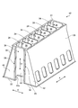
- FIG. 2 is a perspective view showing the frame of this embodiment.
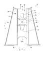
- FIG. 3 is a front view showing the frame.
- FIG. 4 is a detail view of the main part of the frame representing the cooling oil passage structure of the present embodiment.
- FIG. 5 is a perspective view of a main part of the frame representing the cooling oil passage structure.
- FIG. 6 is a cross-sectional view of the main part showing the cooling oil passage structure.
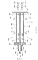
- 7 is a sectional view taken along line VII-VII in FIG. 8 is a cross-sectional view taken along the line VIII-VIII in FIG.
- FIG. 1 is a schematic configuration diagram showing a diesel engine of the present embodiment.
- the diesel engine 10 is, for example, a two-stroke, one-cycle, uniflow scavenging crosshead type internal combustion engine that is used as a main engine for ship propulsion.
- the diesel engine 10 includes a base plate 11 positioned below, a frame 12 provided on the base plate 11, and a cylinder jacket 13 provided on the frame 12.
- the base plate 11, the frame 12, and the cylinder jacket 13 are integrally fastened and fixed by a plurality of tie bolts (connecting members) 14 and nuts 15 extending in the piston axial direction.
- the cylinder liner 16 is disposed in the cylinder jacket 13, and a cylinder cover 17 is fixed to an upper portion thereof to define a space portion, and a piston 18 is provided in the space portion so as to be able to reciprocate up and down.
- the cylinder cover 17 is provided with an exhaust valve 20, and the exhaust valve 20 can be opened and closed by a valve operating device 21.
- the exhaust valve 20 forms a combustion chamber 19 together with the cylinder liner 16, the cylinder cover 17, and the piston 18.
- the exhaust valve 20 opens and closes the combustion chamber 19 and the exhaust pipe 22.
- fuel for example, low-quality oil, natural gas, or a mixed fuel thereof supplied from a fuel injection pump (not shown) to the combustion chamber 19 and a combustion gas (for example, compressed by a compressor (not shown)) , Air, EGR gas, or a mixed gas thereof, etc.
- a combustion gas for example, compressed by a compressor (not shown)
- Air for example, EGR gas, or a mixed gas thereof, etc.
- the piston 18 reciprocates in the direction of the piston axis by the energy generated by the combustion.
- the exhaust valve 20 is operated by the valve operating device 21 to open the combustion chamber 19
- the exhaust gas generated by the combustion is pushed out to the exhaust pipe 22, while the combustion gas is discharged from a scavenging port (not shown).
- the upper end of the piston rod 23 is connected to the lower end of the piston 18.
- the base plate 11 constitutes a crankcase, and a crankshaft 24 is rotatably supported by a bearing 25.
- the crankshaft 24 is rotatably connected to the lower end portion of the connecting rod 27 via a crank 26.
- the frame 12 is arranged such that guide plates 28 provided along the piston axis direction form a pair with a predetermined interval in the width direction.
- a crosshead pin connected to the lower end of the piston rod 23 and a crosshead bearing connected to the upper end of the connecting rod 27 connected to the crankshaft 24 are respectively rotated in the lower half of the crosshead pin. It is connected freely.
- the cross head 29 is disposed between the pair of guide plates 28 and is supported so as to be movable along the guide plates 28.
- FIG. 2 is a perspective view showing the frame of this embodiment
- FIG. 3 is a front view showing the frame.
- the frame 12 includes a top plate 31, a bottom plate 32, side plates 33, and a plurality of partition walls 34.
- the top plate 31 is disposed in the upper part of the piston axial direction Z and is connected to the cylinder jacket 13 (see FIG. 1).
- the bottom plate 32 is disposed below the piston axial direction Z and is connected to the base plate 11 (see FIG. 1).
- the side plate 33 is disposed on the left and right side portions in the width direction Y of the diesel engine 10, one end portion (lower end portion) in the piston axial direction Z is connected to the bottom plate 32, and the other end portion (upper end portion) is connected to the top plate 31.
- the plurality of partition walls 34 are arranged in parallel along the crankshaft direction X with a predetermined interval.
- a plurality of space portions 35 are formed along the crankshaft direction X by the top plate 31, the bottom plate 32, the side plates 33, and the partition walls 34.
- Each of the space portions 35 is a space portion in which the cross head 29 can be supported and moved by the left and right guide plates 28.
- the cross head 29 is accommodated in the space portion 35 and extends along the piston axial direction Z. Can reciprocate.
- the partition wall 34 has a center plate 41 and an intermediate plate 42.
- the central plate 41 forms a central portion of the partition wall 34 in the width direction Y of the internal combustion engine.
- Each intermediate plate 42 forms both end portions of the partition wall 34 in the width direction Y.
- the guide plate 28 is disposed between the central plate 41 and each intermediate plate 42 in the partition wall 34 and connected by welding.
- the central plate 41 is a flat plate having a rectangular shape in which a notch 41 a is formed in the lower part in the piston axial direction Z, and is arranged so that the notch 41 a is located in the lower part of the partition wall 34. Both ends of the center plate 41 in the width direction Y are connected to the guide plate 28 by welding.
- the crosshead 29 is composed of a guide shoe 51 and a crosshead pin 52.
- the cross head pin 52 is connected to the piston rod 23 and the connecting rod 27.
- the guide shoe 51 is integrally connected to the cross head pin 52. Therefore, when the piston 18 (see FIG. 1) reciprocates in the piston axial direction Z, the piston rod 23 integrated with the piston 18 reciprocates along the piston axial direction Z. At this time, the guide shoe 51 is moved to the left and right guide plates. It reciprocates along 28.
- the connecting rod 27 rotates under the cross head pin 52 with the cross head pin 52 as a fulcrum as the cross head pin 52 reciprocates along the piston axial direction Z.
- the piston 18 is heated by the combustion gas, it is cooled by supplying cooling oil from the outside to the inside.
- the cooling oil is supplied from the outside to the cross head 29, supplied to the piston 18 through the cooling oil supply passage in the cross head pin 52 and the piston rod 23, and cools the piston 18. Then, the cooling oil that has cooled the piston 18 is discharged into the space portion 35 of the frame 12.
- the cooling oil is properly supplied to the piston 18 and whether or not the temperature of the cooling oil supplied and cooled to the piston 18 is within an appropriate temperature range.
- a part of the cooling oil discharged to the space portion 35 of the frame 12 is discharged to the outside of the frame 12 through the cooling oil discharge channel, and the temperature of the cooling oil is measured.
- FIG. 4 is a detail view of the main part of the frame representing the cooling oil passage structure of the present embodiment
- FIG. 5 is a perspective view of the main part of the frame representing the cooling oil path structure.
- the cooling oil passage structure of the present embodiment allows a part of the cooling oil discharged into the space 35 (see FIG. 3) to pass through the guide plate 28 at the lower part of the frame 12.
- a cooling oil discharge passage 61 is provided to guide the outside of the space 35.
- the cooling oil discharge channel 61 includes a cooling oil discharge channel 61A arranged on one side of the partition wall 34 and a cooling oil discharge channel 61B arranged on the other side, and each cooling oil discharge channel In 61A and 61B, some constituent members are shared.
- the cooling oil discharge channel 61 includes a cooling oil receiving portion 62, cooling oil guide portions 63A and 63B, cooling oil storage portions 64A and 64B, and through portions 65A and 65B.
- the cooling oil receiving part 62 is shared by the paths 61A and 91B.
- the cooling oil receiving portion 62 has a box shape with an opening 62a formed in the upper portion, and the length in the width direction Y is shorter than the length in the width direction Y of the central plate 41, and the length in the crankshaft direction X is shorter.
- the center plate 41 is wider than the length in the crankshaft direction X.
- the cooling oil receiving portion 62 is located at the lower end portion (below the notch portion 41 a) in the piston axial direction Z of the central plate 41 between the guide plates 28 and is disposed along the central plate 41.
- the mounting plate 71 is disposed along the piston axial direction Z, the upper end portion is in close contact with the flat surface portion of the central plate 41 on the side where the cooling oil discharge passage 61B is disposed, and is fixed to the central plate 41 with a plurality of bolts 72. Has been.
- the lower end portion of the mounting plate 71 enters the inside from the opening 62 a of the cooling oil receiving portion 62 and is fixed to the bottom surface portion.
- the interior of the cooling oil receiving portion 62 is partitioned by a mounting plate 71 into a receiving portion on the cooling oil discharge channel 61A side and a receiving portion on the cooling oil discharge channel 61B side.
- Each of the cooling oil guide portions 63A and 63B has an L shape, is disposed below the cooling oil receiving portion 62, and has a width that is the same as the width of the cooling oil receiving portion 62.
- Each of the cooling oil guide portions 63A and 63B has an upper end portion along the piston axial direction Z fixed to the lower surface of the cooling oil receiving portion 62, and a lower end portion along the width direction Y fixed to the inner surface of one guide plate 28. .
- Each of the cooling oil guide portions 63A and 63B is an independent flow path, and the upper end portion thereof communicates with each receiving portion in the cooling oil receiving portion 62 partitioned by the mounting plate 71.
- Each of the cooling oil reservoirs 64A and 64B is disposed outside the space 35, and the length in the crankshaft direction X is set to be the same as the length of the guide plate 28 in the crankshaft direction X.
- Each of the cooling oil reservoirs 64 ⁇ / b> A and 64 ⁇ / b> B is disposed along the bottom plate 32 and the intermediate plate 42 between the guide plate 28 and the side plate 33.
- Each of the cooling oil reservoirs 64A and 64B is an independent reservoir and a flow path.
- the through portions 65A and 65B are through holes provided in the guide plate 28 so as to communicate the cooling oil guide portions 63A and 63B and the cooling oil storage portions 64A and 64B.
- the penetrating portions 65A and 65B penetrate in the plate thickness direction (width direction Y) of the guide plate 28 and are arranged side by side in the crankshaft direction X of the guide plate 28, and one end portion is provided for each cooling oil guide portion 63A and 63B. The other end communicates with each of the cooling oil reservoirs 64A and 64B.
- Each of the cooling oil reservoirs 64A and 64B is disposed in the horizontal direction along the width direction Y, and one end in the longitudinal direction communicates with each of the cooling oil guides 63A and 63B via the through portions 65A and 65B.
- Thermometers 66A and 66B and temperature sensors 67A and 67B are provided as temperature detectors for detecting the temperature of the cooling oil stored and flowing in the respective cooling oil reservoirs 64A and 64B.
- the thermometers 66A and 66B can display the detected temperature of the cooling oil and can be visually recognized by a person.
- the temperature sensors 67 ⁇ / b> A and 67 ⁇ / b> B output the detected temperature of the cooling oil to an engine control unit (not shown), and the engine control unit uses the input temperature of the cooling oil for controlling the diesel engine 10.
- the thermometers 66A and 66B and the temperature sensors 67A and 67B are fixed to the side plate 33, and the detection unit is immersed in the cooling oil stored in the cooling oil storage units 64A and 64B.
- FIG. 6 is a cross-sectional view of the main part showing the cooling oil passage structure
- FIG. 7 is a cross-sectional view taken along the line VII-VII in FIG. 6
- FIG. 8 is a cross-sectional view taken along the line VIII-VIII in FIG.
- Each of the cooling oil discharge passages 61A and 61B is disposed so as to sandwich the partition wall 34 in the crankshaft direction X, and is provided substantially symmetrically with respect to the partition wall 34. The explanation will focus on the discharge channel 61A.
- each of the cooling oil guide portions 63 ⁇ / b> A and 63 ⁇ / b> B has a pair of plate members 81 a and 81 b having a U-shaped cross-sectional shape fixed to each other with a partition plate 82 interposed therebetween. The two flow paths are formed and the ends are fixed to the guide plate 28 by bolts 83a and 83b.
- Each of the cooling oil reservoirs 64A and 64B is configured by forming two internal reservoirs (flow paths) by fixing the plate material along the bottom plate 32 and the intermediate plate. That is, the plate material of each of the cooling oil reservoirs 64A and 64B is composed of vertical wall portions 84a and 84b and ceiling portions 85a and 85b.
- the vertical wall portions 84a and 84b are arranged along the piston axial direction Z so as to be parallel to the intermediate plate 42 at a predetermined interval, and the lower end portions abut against the upper surface of the bottom plate 32 via a seal member (not shown). Yes.
- the ceiling portions 85a and 85b are arranged along the horizontal direction so as to be parallel to the bottom plate 32 at a predetermined interval, and one end portion in the crankshaft direction X is connected to the upper end portions of the vertical wall portions 84a and 84b. The end is in contact with the intermediate plate 42 via a seal member (not shown).
- the bolts 86a and 86b penetrate the ceiling portions 85a and 85b from above and are screwed to the bottom plate 32, so that the plate materials (vertical wall portions 84a and 84b, ceiling portions 85a and 85b) having an L-shaped cross section are the bottom plates. 32 and the intermediate plate 42.
- each of the cooling oil storage portions 64A and 64B is provided with discharge portions 87a and 87b for discharging the cooling oil in the cooling oil discharge passage 61.
- the discharge portions 87a and 87b are discharge holes through which the cooling oil stored inside is overflowed and discharged to the outside.
- the discharge portions 87a and 87b are provided on one end side and the other end side in the longitudinal direction (width direction Y) of the respective cooling oil storage portions 64A and 64B.
- each cooling oil storage part 64A, 64B is provided with a discharge hole (not shown) at the lower part on the end side where the thermometers 66A, 66B and the temperature sensors 67A, 67B are arranged.
- the discharge hole has a passage area smaller than the passage areas of the through portions 65A and 65B. Therefore, when each cooling oil reservoir 64A, 64B is supplied with cooling oil to one end side by each through portion 65A, 65B, a part is discharged from the discharge hole on the other end side.
- each of the cooling oil storage units 64A and 64B has a larger supply amount per unit time than a discharge amount per unit time, so the storage amount of the cooling oil increases and the cooling oil overflows from the discharge units 87a and 87b. It is discharged outside.
- the supply of the cooling oil is stopped, the stored cooling water is not discharged from the discharge holes on the other end side of each of the cooling oil storage portions 64A and 64B.
- the cooling oil supplied to the cross head 29 is contained in the cross head pin 52 and the piston rod 23.
- the cooling oil supply passage is supplied to the piston 18 to cool the piston 18.
- the cooling oil that has cooled the piston 18 is discharged toward the partition wall 34 that partitions the space portion 35.
- a part of the cooling oil that has flowed down through the central plate 41 enters the cooling oil receiving portion 62 and is discharged to the outside through the cooling oil discharge passage 61.
- the cooling oil receiving part 62 receives a part of the cooling oil flowing down along each flat part of the central plate 41 by each receiving part, and the cooling oil received by the cooling oil receiving part 62 is received by each cooling oil guide part.
- the refrigerant flows from 63A and 63B to the cooling oil reservoirs 64A and 64B through the through portions 65A and 65B.
- Each of the cooling oil storage units 64A and 64B increases in storage amount when the cooling oil is supplied from one end thereof.
- the thermometers 66A and 66B measure and display the temperature of the cooling oil in each of the cooling oil reservoirs 64A and 64B, and the temperature sensors 67A and 67B indicate the temperature of the cooling oil in each of the cooling oil reservoirs 64A and 64B. Is measured and output.
- the diesel engine 10 is properly operated. Can be judged. If the temperature difference of the cooling oil in each of the cooling oil storage portions 64A and 64B of each cylinder detected by the thermometers 66A and 66B and the temperature sensors 67A and 67B is equal to or less than the preset appropriate temperature difference, the cooling oil is in the piston. 18 can be determined to be properly supplied.
- the top plate 31 disposed at the top, the bottom plate 32 disposed at the bottom, the one side connected to the top plate 31 and the other are disposed on the side.
- a plurality of spaces 35 penetrating in the piston axial direction Z are divided in the crankshaft direction X by being connected to the side plate 33 whose end is connected to the bottom plate 32, and the top plate 31, the bottom plate 32, and the side plate 33.
- the cooling oil that has cooled the piston 18 is discharged into the space 35 and flows down, but the through portions 65A and 65B pass a part of this cooling oil through the guide plate 28 and outward of the space 35. Lead to discharge.
- the state of the cooling oil temperature, flow, etc.
- the cooling oil receiving portion 62 provided in the partition wall 34, the cooling oil guide portions 63A and 63B that communicate the cooling oil receiving portion 62 and the inner surface of the guide plate 28, and the space portion 35 outward.
- the cooling oil storage portions 64A and 64B are provided, and the through portions 65A and 65B are provided so as to communicate the cooling oil guide portions 63A and 63B with the cooling oil storage portions 64A and 64B. Accordingly, the cooling oil flowing down along the partition wall 34 is received by the cooling oil receiving portion 62, flows from the cooling oil receiving portion 62 to the cooling oil guide portions 63A, 63B, and passes through the through portions 65A, 65B provided in the guide plate 28. Therefore, it will flow to the cooling oil reservoirs 64A and 64B arranged outside the space portion 35, and a part of the cooling oil discharged into the space portion 35 will be properly processed without disturbing the operation of the crosshead 29. It can be discharged to the outside.
- the frame of the present embodiment is provided with discharge portions 87a and 87b for discharging the cooling oil stored in the cooling oil storage portions 64A and 64B. Accordingly, the cooling oil supplied from the through portions 65A and 65B to the cooling oil storage portions 64A and 64B is discharged from the discharge portions 87a and 87b while being stored in the cooling oil storage portions 64A and 64B. By suppressing the stagnation of the cooling oil in 64A and 64B, when detecting the state of this cooling oil, the state of the new cooling oil discharged into the space 35 can be detected at all times.
- the cooling oil reservoirs 64A and 64B are arranged along the bottom plate 32. Accordingly, the bottom plate 32 can be used as a part of the constituent members of the cooling oil reservoirs 64A and 64B, and the structure can be simplified and reduced in size and weight.
- a plurality of center plates 41 in which a plurality of space portions 35 are partitioned and the guide plates 28 are fixed to the respective side portions, and the guide plates 28 and the side plates 33 at the side portions of the center plate 41 are provided.
- an intermediate plate 42 is provided, and cooling oil reservoirs 64A and 64B are disposed along the intermediate plate 42. Therefore, the intermediate plate 42 can be used as a part of the constituent members of the cooling oil reservoirs 64A and 64B, and the structure can be simplified and reduced in size and weight.
- the cooling oil reservoirs 64A and 64B vertical wall portions 84a and 84b whose lower ends are in contact with the bottom plate 32 with a predetermined interval from the intermediate plate 42, and one end with a predetermined interval from the bottom plate 32 are provided.
- Ceiling portions 85a and 85b which are connected to the upper end portions of the vertical wall portions 84a and 84b and whose other end portions contact the intermediate plate 42, are provided. Accordingly, the bottom plate 32 and the intermediate plate 42 are used as a part of the constituent members of the cooling oil reservoirs 64A and 64B, and the vertical wall portions 84a and 84b and the ceiling portions 85a and 85b are provided, thereby simplifying the structure and reducing the size and weight. Can be achieved.
- the cooling oil receiving portion 62 is disposed below the center plate 41, and the cooling oil guide portions 63A and 63B are disposed below the cooling oil receiving portion 62. Therefore, the cooling oil receiving portion 62 and the cooling oil guide portions 63A and 63B can be easily disposed outside the operating area of the crosshead 29.
- the cooling oil reservoirs 64A and 64B are arranged on both sides of the partition wall 34 and are provided so as to sandwich the partition wall 34 therebetween. Therefore, the plurality of cooling oil reservoirs 64A and 64B are centrally arranged, so that the structure can be simplified and the workability can be improved.
- the cooling oil reservoirs 64A and 64B are provided only on one side of the partition wall 34 in the width direction Y. Therefore, the plurality of cooling oil reservoirs 64A and 64B are centrally arranged, so that the structure can be simplified and the workability can be improved.
- thermometers 66A and 66B and temperature sensors 67A and 67B for detecting the temperature of the cooling oil stored in the cooling oil storage portions 64A and 64B are provided. Therefore, the temperature of the cooling oil discharged into the space 35 can be easily detected by the thermometers 66A and 66B and the temperature sensors 67A and 67B, and the operating state of the diesel engine 10 can be easily estimated.
- thermometers 66A and 66B and the temperature sensors 67A and 67B are fixed to the side plate 33. Accordingly, it is possible to simplify the structure by eliminating the need for a mounting bracket or the like.
- the base plate 11, the frame 12 provided on the base plate 11, the cylinder jacket 13 provided on the frame 12, the base plate 11 and the frame 12 are provided.
- a plurality of tie bolts 14 penetrating and connecting to the cylinder jacket 13 are provided.
- the cooling oil that has cooled the piston 18 in the frame 12 is discharged into the space portion 35 and flows down, but the cooling oil discharge passage passes through a part of the cooling oil through the guide plate 28. It leads to the outside of the part 35 and discharges. For this reason, when detecting the state of the cooling oil (temperature, flow, etc.), it is only necessary to arrange various detectors outside the space 35, and it is not necessary to use a highly heat-resistant detector. Therefore, it is not necessary to lay wiring from the inside to the space portion 35, and the apparatus cost can be reduced.
- the cooling oil receiving portion 62 is disposed below the notch portion 41a in the center plate 41, but is not limited to this position.
- the cooling oil receiving portion 62 may be disposed below the moving area of the cross head 29 moving in the piston axial direction Z, and may be directly fixed to the central plate 41.
- each of the cooling oil guide portions 63A and 63B is configured with the partition plate 82 sandwiched between the pair of plate materials 81a and 81b having a U-shaped cross-sectional shape, but is limited to this configuration. is not.
- each of the cooling oil guide portions 63A and 63B may be a pipe such as a cylinder or a square tube.
- each of the cooling oil reservoirs 64A and 64B is configured by fixing an L-shaped cross-sectional plate material including the vertical wall portions 84a and 84b and the ceiling portions 85a and 85b to the bottom plate 32 and the intermediate plate 42.
- a plate material or a hollow container having a U-shaped cross section may be fixed to the bottom plate 32 or the intermediate plate 42.
- the positions of the respective cooling oil reservoirs 64 ⁇ / b> A and 64 ⁇ / b> B may be fixed and arranged on the intermediate plate 42 above the bottom plate 32.
- each cooling oil storage part 64A, 64B is not restricted to horizontal arrangement
- the through portions 65A and 65B are through holes penetrating the guide plate 28.
- the through portions 65A and 65B may be notched portions in which the end surface of the guide plate 28 is notched. What is necessary is just to block.
Landscapes
- Engineering & Computer Science (AREA)
- Mechanical Engineering (AREA)
- General Engineering & Computer Science (AREA)
- Chemical & Material Sciences (AREA)
- Combustion & Propulsion (AREA)
- Cylinder Crankcases Of Internal Combustion Engines (AREA)
- Lubrication Of Internal Combustion Engines (AREA)
Abstract
架構及びクロスヘッド式内燃機関において、頂部に配置される天板(31)と、底部に配置される底板(32)と、側部に配置されて一端部が天板(31)に接続されると共に他端部が底板(32)に接続される側板(33)と、天板(31)と底板(32)と側板(33)に接続されることでピストン軸方向(Z)に貫通する複数の空間部(35)がクラング軸方向(X)に複数区画される複数の隔壁(34)と、隔壁(34)に固定されて空間部(35)内に排出された冷却油の一部を空間部(35)の外方に導く貫通部(65A,65B)が形成されたガイド板ガイド板(28)とを設ける。
Description
本発明は、ディーゼルエンジンやガスエンジンなどの内燃機関を構成する架構、この架構を備えるクロスヘッド式内燃機関に関するものである。
一般に、シリンダ内で燃料を燃焼させて動力を発生させるガスエンジンやガソリンエンジンなどの内燃機関は、複数のシリンダの下方にシリンダ配列方向に沿ってクランクシャフトが配置されている。クランクシャフトは、ピストンに接続されており、軸受を介してクランクケースに回転自在に支持されている。一方、大型船舶に搭載されるボアストローク比の大きい内燃機関においては、ピストンとクランクシャフトとの間にクロスヘッドが設けられる。クロスヘッド式内燃機関は、クランクシャフトが収容される台板の上部に架構が配置され、この架構の上部にシリンダジャケットが配置され、複数のタイボルトにより一体に連結されて構成されている。
そのため、ピストンがピストン軸方向に沿って往復移動すると、ピストンと共にピストン棒がピストン軸方向に沿って往復移動することにより、クロスヘッドが架構のガイド板に沿ってピストン軸方向に沿って往復移動する。これにより、クロスヘッドのクロスヘッドピンは、クロスヘッド軸受を介して連接棒に回転駆動力を加え、連接棒の下端部に接続されるクランクがクランク運動し、クランクシャフトを回転させる。
このように構成されたクロスヘッド式内燃機関では、ピストンが燃焼ガスにより高温となることから、外部からピストンの内部に冷却油を供給して冷却している。この冷却油は、クロスヘッドに供給され、このクロスヘッドからピストン棒内の冷却油供給通路を通ってピストンに供給されて冷却し、ピストン棒内の冷却油戻り通路を通って再びクロスヘッドに戻る。クロスヘッドに戻った冷却油は、架構の空間部内に排出され、下部の台板に貯留される。
このようなクロスヘッド式内燃機関としては、例えば、下記特許文献1に記載されたものがある。
上述したクロスヘッド式内燃機関では、ピストンを冷却する冷却油の温度を常時検出する必要がある。従来、架構内に温度計を配置し、ピストンを冷却してクロスヘッドに戻った後に架構の空間部内に排出される冷却油の温度をこの温度計により計測している。この場合、温度計を架構内に配置することから、外部から架構内の温度計まで配線を布設する必要があり、構造が複雑となってコストが増加してしまうという問題がある。また、温度計を高温領域である架構内に配置することから、耐熱性の高い温度計を使用する必要があり、この点でもコスト増を招いてしまう。
本発明は、上述した課題を解決するものであり、装置コストの低減を図る架構及びクロスヘッド式内燃機関を提供することを目的とする。
上記の目的を達成するための本発明の架構は、頂部に配置される天板と、底部に配置される底板と、側部に配置されて一端部が前記天板に接続されると共に他端部が前記底板に接続される側板と、前記天板と前記底板と前記側板に接続されることで空間部が複数区画される複数の隔壁と、前記隔壁に固定されて前記空間部内に排出された冷却油の一部を前記空間部の外方に導く貫通部が形成されたガイド板と、を備えることを特徴とするものである。
従って、例えば、ピストンを冷却した冷却油は、空間部内に排出された後、貫通部により空間部の外方に導かれる。そのため、この冷却油の状態を検出する場合、空間部の外部に各種の検出器を配置すればよく、耐熱性の高い検出器を使用する必要がなく、また、外部から空間部内への配線の布設が不要となり、装置コストの低減を図ることができる。
本発明の架構では、前記隔壁に設けられる冷却油受部と、前記冷却油受部と前記ガイド板の内面とを連通する冷却油案内部と、前記空間部の外方に配置される冷却油貯留部と、を備え、前記ガイド板に形成された前記貫通部は、前記冷却油案内部と前記冷却油貯留部を連通することを特徴としている。
従って、隔壁に沿って流れ落ちる冷却油は、冷却油受部により受け止められ、冷却油受部から冷却油案内部に流れ、ガイド板に形成された貫通部を通って空間部の外方に配置される冷却油貯留部に流れることとなり、空間部内に排出された冷却油の一部をクロスヘッドの動作を邪魔することなく、適正に外部に排出することができる。
本発明の架構では、前記冷却油貯留部は、貯留された冷却油を排出する排出部が設けられることを特徴としている。
従って、貫通部から冷却油貯留部に供給された冷却油は、冷却油貯留部で貯留されながら排出部から排出されることとなり、冷却油貯留部における冷却油の停滞を抑制することで、この冷却油の状態を検出する場合、常時、空間部に排出された新しい冷却油の状態を検出することができる。
本発明の架構では、前記冷却油貯留部は、前記底板に沿って配置されることを特徴としている。
従って、冷却油貯留部を底板に沿って配置することで、冷却油貯留部の構成部材の一部として底板を用いることができ、構造の簡素化及び小型軽量化を図ることができる。
本発明の架構では、前記隔壁は、前記複数の空間部を区画して各側部に前記ガイド板が固定される複数の中央板と、前記中央板の側部で前記ガイド板と前記側板とを連結する中間板とを備え、前記冷却油貯留部は、前記中間板に沿って配置されることを特徴としている。
従って、冷却油貯留部を中間板に沿って配置することで、冷却油貯留部の構成部材の一部として中間板を用いることができ、構造の簡素化及び小型軽量化を図ることができる。
本発明の架構では、前記冷却油貯留部は、前記中間板に所定間隔を空けて下端部が前記底板に当接する縦壁部と、前記底板に所定間隔を空けて一端部が前記縦壁部の上端部に連結されて他端部が前記中間板に当接する天井部とを備えることを特徴としている。
従って、冷却油貯留部の構成部材の一部として底板と中間板を用いると共に、縦壁部と天井部を設けることで、構造の簡素化及び小型軽量化を図ることができる。
本発明の架構では、前記冷却油受部は、前記中央板の下部に配置され、前記冷却油案内部は、前記冷却油受部の下方に配置されることを特徴としている。
従って、冷却油受部を中央板の下部に配置し、冷却油案内部を冷却油受部の下方に配置することで、冷却油受部と冷却油案内部をクロスヘッドの動作領域外へ容易に配置することができる。
本発明の架構では、前記冷却油貯留部は、前記隔壁挟み込むように設けられることを特徴としている。
従って、冷却油貯留部を隔壁挟み込むように設けることで、複数の冷却油貯留部を集中配置することとなり、構造の簡素化及び施工性の向上を図ることができる。
本発明の架構では、前記冷却油貯留部は、前記隔壁における幅方向の一方側だけに設けられることを特徴としている。
従って、冷却油貯留部を隔壁における幅方向の一方側だけに設けることで、複数の冷却油貯留部を集中配置することとなり、構造の簡素化及び施工性の向上を図ることができる。
本発明の架構では、前記冷却油貯留部に貯留される冷却油の温度を検出する温度検出器が設けられることを特徴としている。
従って、温度検出器により空間部に排出された冷却油の温度を容易に検出することができる。
本発明の架構では、前記温度検出器は、前記側板に固定されることを特徴としている。
従って、温度検出器を側板を利用して固定することで、別途、取付ブラケットなどを不要として構造の簡素化を図ることができる。
また、本発明のクロスヘッド式内燃機関は、台板と、前記台板上に設けられる前記架構と、前記架構上に設けられるシリンダジャケットと、前記台板と前記架構と前記シリンダジャケットを貫通して連結する複数の連結部材と、を備えることを特徴とするものである。
従って、架構内で、ピストンを冷却した冷却油は、空間部内に排出された後、冷却油排出流路により一部がガイド板を貫通して空間部の外方に導かれる。そのため、この冷却油の状態を検出する場合、空間部の外部に各種の検出器を配置すればよく、耐熱性の高い検出器を使用する必要がなく、また、外部から空間部内への配線の布設が不要となり、装置コストの低減を図ることができる。
本発明の架構及びクロスヘッド式内燃機関によれば、空間部内に排出された冷却油の一部をガイド板を貫通して空間部の外方に導く冷却油排出流路を設けるので、装置コストの低減を図ることができる。
以下に添付図面を参照して、本発明に係る架構及びクロスヘッド式内燃機関の好適な実施形態を詳細に説明する。なお、この実施形態により本発明が限定されるものではなく、また、実施形態が複数ある場合には、各実施形態を組み合わせて構成するものも含むものである。
図1は、本実施形態のディーゼルエンジンを表す概略構成図である。
本実施形態にて、図1に示すように、ディーゼルエンジン10は、例えば、船舶推進用の主機として用いられ、2ストローク1サイクルのユニフロー掃気方式のクロスヘッド式内燃機関である。このディーゼルエンジン10は、下方に位置する台板11と、台板11上に設けられる架構12と、架構12上に設けられるシリンダジャケット13とを備えている。この台板11と架構12とシリンダジャケット13は、ピストン軸方向に延在する複数のタイボルト(連結部材)14及びナット15により一体に締結されて固定されている。
シリンダライナ16は、シリンダジャケット13内に配置され、上部にシリンダカバー17が固定されて空間部を区画しており、この空間部内にピストン18が上下に往復動自在に設けられる。また、シリンダカバー17は、排気弁20が設けられており、排気弁20は、動弁装置21により開閉可能となっている。排気弁20は、シリンダライナ16、シリンダカバー17、およびピストン18とともに燃焼室19を形成する。排気弁20は、燃焼室19と排気管22とを開閉するものである。
そのため、燃焼室19に対して、図示しない燃料噴射ポンプから供給された燃料(例えば、低質油、天然ガス、または、その混合燃料など)と、図示しない圧縮機により圧縮された燃焼用ガス(例えば、空気、EGRガス、または、その混合ガスなど)が供給されることで、燃焼室19で燃料と燃焼用ガスが燃焼する。そして、この燃焼で発生したエネルギによりピストン18がピストン軸方向に往復動する。このとき、動弁装置21により排気弁20が作動して燃焼室19が開放されると、燃焼によって生じた排ガスが排気管22に押し出される一方、図示しない掃気ポートから燃焼用ガスが燃焼室19に導入される。
ピストン18は、下端部にピストン棒23の上端部が連結されている。台板11は、クランクケースを構成しており、クランクシャフト24が軸受25により回転自在に支持されている。このクランクシャフト24は、クランク26を介して連接棒27の下端部が回動自在に連結されている。架構12は、ピストン軸方向に沿って設けられるガイド板28が幅方向に所定間隔を空けて一対をなすように配置されている。クロスヘッド29は、ピストン棒23の下端部に接続されるクロスヘッドピンとクランクシャフト24に連接される連接棒27の上端部に接続されるクロスヘッド軸受とが、クロスヘッドピンの下半部においてそれぞれ回動自在に連結される。このクロスヘッド29は、一対のガイド板28の間に配置され、このガイド板28に沿って移動自在に支持される。
そのため、ピストン18がピストン軸方向に沿って往復移動すると、ピストン18と共にピストン棒23がピストン軸方向に沿って往復移動することにより、クロスヘッド29がガイド板28に沿ってピストン軸方向に沿って往復移動する。これにより、クロスヘッド29のクロスヘッドピンは、クロスヘッド軸受を介して連接棒27に回転駆動力を加える。この回転駆動力により、連接棒27の下端部に接続されるクランク26がクランク運動し、クランクシャフト24を回転させる。
ここで、ディーゼルエンジン10を構成する架構12について詳細に説明する。図2は、本実施形態の架構を表す斜視図、図3は、架構を表す正面図である。
図2及び図3に示すように、架構12は、天板31と、底板32と、側板33と、複数の隔壁34とから構成されている。天板31は、ピストン軸方向Zの上部に配置されてシリンダジャケット13(図1参照)に接続される。底板32は、ピストン軸方向Zの下部に配置されて台板11(図1参照)に接続される。側板33は、ディーゼルエンジン10の幅方向Yの左右の側部に配置されてピストン軸方向Zにおける一端部(下端部)が底板32に接続され、他端部(上端部)が天板31に接続される。複数の隔壁34は、クランク軸方向Xに沿って一定間隔を空けて平行に配置される。
この架構12は、天板31と底板32と側板33と各隔壁34により、クランク軸方向Xに沿って複数の空間部35が形成されている。この各空間部35は、それぞれクロスヘッド29が左右のガイド板28に支持されて移動することができる空間部であり、クロスヘッド29は、この空間部35に収容され、ピストン軸方向Zに沿って往復移動することができる。
隔壁34は、中央板41と、中間板42とを有している。中央板41は、隔壁34における内燃機関の幅方向Yの中央部分を形成するものである。各中間板42は、隔壁34における幅方向Yの両端部分を形成するものである。ガイド板28は、隔壁34における中央板41と各中間板42との間に配置され、溶接により接続されている。中央板41は、ピストン軸方向Zの下部に切欠部41aが形成された矩形状をなす平面板であり、切欠部41aが隔壁34の下部に位置するように配置される。中央板41は、幅方向Yにおける両端部がガイド板28に溶接により接続されている。
ところで、クロスヘッド29は、ガイドシュー51と、クロスヘッドピン52とから構成されている。クロスヘッドピン52はピストン棒23と、連接棒27とに連結されている。ガイドシュー51は、クロスヘッドピン52に一体に連結されている。そのため、ピストン18(図1参照)がピストン軸方向Zに往復移動すると、ピストン18と一体のピストン棒23がピストン軸方向Zに沿って往復移動し、このとき、ガイドシュー51が左右のガイド板28に沿って往復移動する。連接棒27は、クロスヘッドピン52がピストン軸方向Zに沿って往復移動することにより、クロスヘッドピン52を支点としてクロスヘッドピン52の下部を回動する。
また、ピストン18は、燃焼ガスにより高温となることから、外部から内部に冷却油を供給して冷却している。この冷却油は、外部からクロスヘッド29に供給され、クロスヘッドピン52及びピストン棒23内の冷却油供給通路を通ってピストン18に供給され、このピストン18を冷却する。そして、ピストン18を冷却した冷却油は、架構12の空間部35に排出される。
更に、ディーゼルエンジン10では、冷却油がピストン18に適正に供給されているかどうか、ピストン18に供給されて冷却した冷却油の温度が適正温度範囲にあるかどうかを検出する必要がある。本実施形態では、架構12の空間部35に排出された冷却油の一部を冷却油排出流路により架構12の外部に排出し、冷却油の温度を計測している。
以下、本実施形態の冷却油路構造の詳細について説明する。図4は、本実施形態の冷却油路構造を表す架構の要部詳細図、図5は、冷却油路構造を表す架構の要部斜視図である。
本実施形態の冷却油路構造は、図4及び図5に示すように、架構12の下部に空間部35(図3参照)内に排出された冷却油の一部をガイド板28を貫通して空間部35の外方に導く冷却油排出流路61が設けられている。この冷却油排出流路61は、隔壁34の一方面側に配置される冷却油排出流路61Aと、他方面側に配置される冷却油排出流路61Bとを備え、各冷却油排出流路61A,61Bは、一部の構成部材が共用化されている。
冷却油排出流路61は、冷却油受部62と、冷却油案内部63A,63Bと、冷却油貯留部64A,64Bと、貫通部65A,65Bとから構成されており、各冷却油排出流路61A,91Bは、冷却油受部62が共用化されている。
冷却油受部62は、上部に開口部62aが形成された箱型形状をなし、幅方向Yにおける長さが中央板41の幅方向Yにおける長さよりも短く、クランク軸方向Xにおける長さが中央板41のクランク軸方向Xにおける長さよりも広いものとなっている。冷却油受部62は、ガイド板28の間で、中央板41のピストン軸方向Zにおける下端部(切欠部41aの下方)に位置し、中央板41に沿って配置されている。取付板71は、ピストン軸方向Zに沿って配置され、上端部が中央板41における冷却油排出流路61Bが配置される側の平面部に密着し、複数のボルト72により中央板41に固定されている。取付板71は、下端部が冷却油受部62の開口部62aから内部に侵入し、底面部に固定されている。冷却油受部62は、取付板71により内部が冷却油排出流路61A側の受部と冷却油排出流路61B側の受部とに区画されている。そのため、空間部35に排出され、中央板41における一方の平面部を伝って流れ落ちる冷却油は、一部が冷却油受部62における冷却油排出流路61A側の受部に入り、中央板41における他方の平面部を伝って流れ落ちる冷却油は、一部が冷却油受部62における冷却油排出流路61B側の受部に入る。
各冷却油案内部63A,63Bは、L字形状をなし、冷却油受部62の下方に配置され、幅が冷却油受部62の幅と同幅に設定されている。各冷却油案内部63A,63Bは、ピストン軸方向Zに沿う上端部が冷却油受部62の下面に固定され、幅方向Yに沿う下端部が一方のガイド板28の内面に固定されている。各冷却油案内部63A,63Bは、それぞれ独立した流路であり、上端部が取付板71により仕切られた冷却油受部62内の各受部に連通している。
各冷却油貯留部64A,64Bは、空間部35の外方に配置され、クランク軸方向Xにおける長さがガイド板28のクランク軸方向Xにおける長さと同じに設定されている。各冷却油貯留部64A,64Bは、ガイド板28と側板33との間で、底板32と中間板42に沿って配置されている。各冷却油貯留部64A,64Bは、それぞれ独立した貯留部であると共に流路である。貫通部65A,65Bは、各冷却油案内部63A,63Bと各冷却油貯留部64A,64Bを連通するようにガイド板28に設けられた貫通孔である。貫通部65A,65Bは、ガイド板28の板厚方向(幅方向Y)に貫通し、ガイド板28のクランク軸方向Xに並んで設けられており、一端部が各冷却油案内部63A,63Bに連通し、他端部が各冷却油貯留部64A,64Bに連通している。
各冷却油貯留部64A,64Bは、幅方向Yに沿って水平方向に配置され、長手方向の一端部が貫通部65A,65Bを介して各冷却油案内部63A,63Bに連通し、他端部に各冷却油貯留部64A,64Bに貯留されると共に流れる冷却油の温度を検出する温度検出器として、温度計66A,66Bと温度センサ67A,67Bが設けられている。この温度計66A,66Bは、検出した冷却油の温度を表示可能であり、人が視認可能となっている。温度センサ67A,67Bは、検出した冷却油の温度を図示しないエンジン制御部に出力し、エンジン制御部は、入力した冷却油の温度をディーゼルエンジン10の制御に使用する。この温度計66A,66Bと温度センサ67A,67Bは、側板33に固定され、検出部が各冷却油貯留部64A,64Bに貯留された冷却油に浸漬されている。
以下、各冷却油排出流路61A,61Bの冷却油案内部63A,63B、冷却油貯留部64A,64B、貫通部65A,65Bについて詳細に説明する。図6は、冷却油路構造を表す要部断面図、図7は、図6のVII-VII断面図、図8は、図6のVIII-VIII断面図である。なお、各冷却油排出流路61A,61Bは、クランク軸方向Xにおいて隔壁34を挟み込むように配置され、この隔壁34に対してほぼ対称に設けられていることから、以下では、一方の冷却油排出流路61Aを中心に説明する。
図6から図8に示すように、各冷却油案内部63A,63Bは、U字断面形状をなす一対の板材81a,81bが仕切板82を間に挟んで互いに固定されることで、内部の2本の流路を形成して構成されており、端部がボルト83a,83bによりガイド板28に固定されている。各冷却油貯留部64A,64Bは、板材が底板32と中間板42に沿って固定されることで、内部の2本の貯留部(流路)を形成して構成されている。即ち、各冷却油貯留部64A,64Bの板材は、縦壁部84a,84bと、天井部85a,85bとから構成されている。縦壁部84a,84bは、中間板42に所定間隔を空けて平行をなすようにピストン軸方向Zに沿って配置され、下端部が図示しないシール部材を介して底板32の上面に当接している。天井部85a,85bは、底板32に所定間隔を空けて平行をなすように水平方向に沿って配置され、クランク軸方向Xの一端部が縦壁部84a,84bの上端部に連結されて他端部が中間板42に図示しないシール部材を介して当接している。そして、ボルト86a,86bが上方から天井部85a,85bを貫通し、底板32に螺合することで、L字断面形状をなす板材(縦壁部84a,84b、天井部85a,85b)が底板32と中間板42に固定される。
また、各冷却油貯留部64A,64Bは、冷却油排出流路61の冷却油を排出する排出部87a,87bが設けられている。排出部87a,87bは、内部に貯留されている冷却油を溢れされて外部に排出される排出孔である。この排出部87a,87bは、各冷却油貯留部64A,64Bにおける長手方向(幅方向Y)の一端部側と他端部側にそれぞれ設けられている。なお、各冷却油貯留部64A,64Bは、温度計66A,66B及び温度センサ67A,67Bが配置されている端部側の下部に図示しない排出孔が設けられている。排出孔は、通路面積が各貫通部65A,65Bの通路面積より小さいものとなっている。そのため、各冷却油貯留部64A,64Bは、各貫通部65A,65Bにより一端部側に冷却油が供給されると、一部が他端部側の排出孔から排出される。但し、各冷却油貯留部64A,64Bは、単位時間当たりの供給量が単位時間当たりの排出量より多いことから、冷却油の貯留量が増加し、冷却油が排出部87a,87bから溢れて外部に排出される。一方、各冷却油貯留部64A,64Bは、冷却油の供給が止まると、貯留されている冷却水が他端部側の排出孔から排出されてなくなる。
このように構成された本実施形態の冷却油路構造において、図1に示すように、ピストン18が往復移動するとき、クロスヘッド29に供給された冷却油は、クロスヘッドピン52及びピストン棒23内の冷却油供給通路を通ってピストン18に供給され、このピストン18を冷却する。そして、ピストン18を冷却した冷却油は、空間部35を区画する隔壁34に向けて排出される。すると、中央板41を伝って流れ落ちた冷却油は、一部が冷却油受部62に入り込み、冷却油排出流路61により外部に排出される。
即ち、冷却油受部62は、中央板41の各平面部を伝って流れ落ちる冷却油の一部を各受部で受け止め、冷却油受部62により受け止められた冷却油は、各冷却油案内部63A,63Bから各貫通部65A,65Bを通って冷却油貯留部64A,64Bに流れる。各冷却油貯留部64A,64Bは、一端部から冷却油が供給されることで貯留量が増加する。このとき、温度計66A,66Bは、各冷却油貯留部64A,64Bの冷却油の温度を計測して表示し、温度センサ67A,67Bは、各冷却油貯留部64A,64Bの冷却油の温度を計測して出力する。
この場合、温度計66A,66Bや温度センサ67A,67Bが検出した各冷却油貯留部64A,64Bの冷却油の温度が予め設定された適正温度範囲にあれば、ディーゼルエンジン10が適正に運転されていると判断できる。また、温度計66A,66Bや温度センサ67A,67Bが検出した各シリンダの各冷却油貯留部64A,64Bの冷却油の温度差が予め設定された適正温度差以下であれば、冷却油がピストン18に適正に供給されていると判断できる。
このように本実施形態の架構にあっては、頂部に配置される天板31と、底部に配置される底板32と、側部に配置されて一端部が天板31に接続されると共に他端部が底板32に接続される側板33と、天板31と底板32と側板33に接続されることでピストン軸方向Zに貫通する複数の空間部35がクランク軸方向Xに複数区画される複数の隔壁34と、隔壁34に固定されて空間部35内に排出された冷却油の一部を空間部35の外方に導く貫通部65A,65Bが形成されたガイド板28とを設けている。
従って、ピストン18を冷却した冷却油は、空間部35内に排出されて流れ落ちるが、貫通部65A,65Bは、この冷却油の一部を、ガイド板28を貫通して空間部35の外方に導いて排出する。そのため、この冷却油の状態(温度や流れなど)を検出する場合、空間部35の外部に各種の検出器を配置すればよく、耐熱性の高い検出器を使用する必要がなく、また、外部から空間部35内への配線の布設が不要となり、装置コストの低減を図ることができる。
本実施形態の架構では、隔壁34に設けられる冷却油受部62と、冷却油受部62とガイド板28の内面とを連通する冷却油案内部63A,63Bと、空間部35の外方に配置される冷却油貯留部64A,64Bとを設け、貫通部65A,65Bは、冷却油案内部63A,63Bと冷却油貯留部64A,64Bを連通するように設けている。従って、隔壁34に沿って流れ落ちる冷却油は、冷却油受部62により受け止められ、冷却油受部62から冷却油案内部63A,63Bに流れ、ガイド板28に設けられる貫通部65A,65Bを通って空間部35の外方に配置される冷却油貯留部64A,64Bに流れることとなり、空間部35内に排出された冷却油の一部をクロスヘッド29の動作を邪魔することなく、適正に外部に排出することができる。
本実施形態の架構では、冷却油貯留部64A,64Bに貯留された冷却油を排出する排出部87a,87bを設けている。従って、貫通部65A,65Bから冷却油貯留部64A,64Bに供給された冷却油は、冷却油貯留部64A,64Bで貯留されながら排出部87a,87bから排出されることとなり、冷却油貯留部64A,64Bにおける冷却油の停滞を抑制することで、この冷却油の状態を検出する場合、常時、空間部35に排出された新しい冷却油の状態を検出することができる。
本実施形態の架構では、冷却油貯留部64A,64Bを底板32に沿って配置している。従って、冷却油貯留部64A,64Bの構成部材の一部として底板32を用いることができ、構造の簡素化及び小型軽量化を図ることができる。
本実施形態の架構では、隔壁として、複数の空間部35を区画して各側部にガイド板28が固定される複数の中央板41と、中央板41の側部でガイド板28と側板33とを連結する中間板42とを設け、冷却油貯留部64A,64Bを中間板42に沿って配置している。従って、冷却油貯留部64A,64Bの構成部材の一部として中間板42を用いることができ、構造の簡素化及び小型軽量化を図ることができる。
本実施形態の架構では、冷却油貯留部64A,64Bとして、中間板42に所定間隔を空けて下端部が底板32に当接する縦壁部84a,84bと、底板32に所定間隔を空けて一端部が縦壁部84a,84bの上端部に連結されて他端部が中間板42に当接する天井部85a,85bを設けている。従って、冷却油貯留部64A,64Bの構成部材の一部として底板32と中間板42を用いると共に、縦壁部84a,84bと天井部85a,85bを設けることで、構造の簡素化及び小型軽量化を図ることができる。
本実施形態の架構では、冷却油受部62を中央板41の下部に配置し、冷却油案内部63A,63Bを冷却油受部62の下方に配置している。従って、冷却油受部62と冷却油案内部63A,63Bをクロスヘッド29の動作領域外へ容易に配置することができる。
本実施形態の架構では、冷却油貯留部64A,64Bを隔壁34の両側に配置し、この隔壁34を挟み込むように設けている。従って、複数の冷却油貯留部64A,64Bを集中配置することとなり、構造の簡素化及び施工性の向上を図ることができる。
本実施形態の架構では、冷却油貯留部64A,64Bを隔壁34における幅方向Yの一方側だけに設けている。従って、複数の冷却油貯留部64A,64Bを集中配置することとなり、構造の簡素化及び施工性の向上を図ることができる。
本実施形態の架構では、冷却油貯留部64A,64Bに貯留される冷却油の温度を検出する温度計66A,66Bと温度センサ67A,67Bを設けている。従って、温度計66A,66Bと温度センサ67A,67Bにより空間部35に排出された冷却油の温度を容易に検出することができ、ディーゼルエンジン10の運転状態を容易に推定することができる。
本実施形態の架構では、温度計66A,66Bと温度センサ67A,67Bを側板33に固定している。従って、別途、取付ブラケットなどを不要として構造の簡素化を図ることができる。
また、本実施形態のクロスヘッド式内燃機関にあっては、台板11と、台板11上に設けられる架構12と、架構12上に設けられるシリンダジャケット13と、台板11と架構12とシリンダジャケット13を貫通して連結する複数のタイボルト14とを設けている。
従って、架構12内で、ピストン18を冷却した冷却油は、空間部35内に排出されて流れ落ちるが、冷却油排出流路は、この冷却油の一部を、ガイド板28を貫通して空間部35の外方に導いて排出する。そのため、この冷却油の状態(温度や流れなど)を検出する場合、空間部35の外部に各種の検出器を配置すればよく、耐熱性の高い検出器を使用する必要がなく、また、外部から空間部35内への配線の布設が不要となり、装置コストの低減を図ることができる。
なお、上述した実施形態では、冷却油受部62を中央板41における切欠部41aの下方に配置したが、この位置に限定されるものではない。冷却油受部62は、ピストン軸方向Zに移動するクロスヘッド29の移動領域よりも下方に配置すればよく、中央板41に直接固定してもよい。
また、上述した実施形態では、各冷却油案内部63A,63Bを、U字断面形状をなす一対の板材81a,81bの間に仕切板82を挟んで構成したが、この構成に限定されるものではない。例えば、各冷却油案内部63A,63Bを円筒や角筒などのパイプとしてもよい。
また、上述した実施形態では、各冷却油貯留部64A,64Bを、縦壁部84a,84bと天井部85a,85bからなるL字断面形状の板材を底板32と中間板42に固定して構成したが、この構成に限定されるものではない。例えば、U字断面形状をなす板材や中空の容器を底板32や中間板42に固定してもよい。そして、各冷却油貯留部64A,64Bの位置は、底板32から離間した上方で、中間板42に固定して配置してもよい。また、各冷却油貯留部64A,64Bは、水平配置に限らず、貫通部65A,65B側を上方に位置させた傾斜状態で配置してもよい。
また、上述した実施形態では、貫通部65A,65Bをガイド板28を貫通した貫通孔としたが、ガイド板28の端面を切欠いた切欠部であってもよく、切欠部の開放側をカバーにより閉塞すればよい。
10 ディーゼルエンジン(クロスヘッド式内燃機関)
11 台板
12 架構
13 シリンダジャケット
14 タイボルト(連結部材)
15 ナット
16 シリンダライナ
17 シリンダカバー
18 ピストン
19 燃焼室
21 動弁装置
22 排気管
23 ピストン棒
24 クランクシャフト
25 軸受
26 クランク
27 連接棒
28 ガイド板
29 クロスヘッド
31 天板
32 底板
33 側板
34 隔壁
35 空間部
41 中央板
41a 切欠部
42 中間板
61,61A,61B 冷却油排出流路
62 冷却油受部
63A,63B 冷却油案内部
64A,64B 冷却油貯留部
65A,65B 貫通部
66A,66B 温度計(温度検出器)
67A,67B 温度センサ(温度検出器)
71 取付板
81a,81b 板材
82 仕切板
84a,84b 縦壁部
85a,85b 天井部
86a,86b ボルト
87a,87b 排出部
11 台板
12 架構
13 シリンダジャケット
14 タイボルト(連結部材)
15 ナット
16 シリンダライナ
17 シリンダカバー
18 ピストン
19 燃焼室
21 動弁装置
22 排気管
23 ピストン棒
24 クランクシャフト
25 軸受
26 クランク
27 連接棒
28 ガイド板
29 クロスヘッド
31 天板
32 底板
33 側板
34 隔壁
35 空間部
41 中央板
41a 切欠部
42 中間板
61,61A,61B 冷却油排出流路
62 冷却油受部
63A,63B 冷却油案内部
64A,64B 冷却油貯留部
65A,65B 貫通部
66A,66B 温度計(温度検出器)
67A,67B 温度センサ(温度検出器)
71 取付板
81a,81b 板材
82 仕切板
84a,84b 縦壁部
85a,85b 天井部
86a,86b ボルト
87a,87b 排出部
Claims (12)
- 頂部に配置される天板と、
底部に配置される底板と、
側部に配置されて一端部が前記天板に接続されると共に他端部が前記底板に接続される側板と、
前記天板と前記底板と前記側板に接続されることで空間部が複数区画される複数の隔壁と、
前記隔壁に固定されて前記空間部内に排出された冷却油の一部を前記空間部の外方に導く貫通部が形成されたガイド板と、
を備えることを特徴とする架構。 - 前記隔壁に設けられる冷却油受部と、
前記冷却油受部と前記ガイド板の内面とを連通する冷却油案内部と、
前記空間部の外方に配置される冷却油貯留部と、
を備え、
前記ガイド板に形成された前記貫通部は、前記冷却油案内部と前記冷却油貯留部を連通する、
ことを特徴とする請求項1に記載の架構。 - 前記冷却油貯留部は、貯留された冷却油を排出する排出部が設けられることを特徴とする請求項2に記載の架構。
- 前記冷却油貯留部は、前記底板に沿って配置されることを特徴とする請求項2または請求項3に記載の架構。
- 前記隔壁は、前記複数の空間部を区画して各側部に前記ガイド板が固定される複数の中央板と、前記中央板の側部で前記ガイド板と前記側板とを連結する中間板とを備え、前記冷却油貯留部は、前記中間板に沿って配置されることを特徴とする請求項2から請求項4のいずれか一項に記載の架構。
- 前記冷却油貯留部は、前記中間板に所定間隔を空けて下端部が前記底板に当接する縦壁部と、前記底板に所定間隔を空けて一端部が前記縦壁部の上端部に連結されて他端部が前記中間板に当接する天井部とを備えることを特徴とする請求項5に記載の架構。
- 前記冷却油受部は、前記中央板の下部に配置され、前記冷却油案内部は、前記冷却油受部の下方に配置されることを特徴とする請求項5または請求項6に記載の架構。
- 前記冷却油貯留部は、前記隔壁を挟み込むように設けられることを特徴とする請求項2から請求項7のいずれか一項に記載の架構。
- 前記冷却油貯留部は、前記隔壁における幅方向の一方側だけに設けられることを特徴とする請求項2から請求項8のいずれか一項に記載の架構。
- 前記冷却油貯留部に貯留される冷却油の温度を検出する温度検出器が設けられることを特徴とする請求項2から請求項9のいずれか一項に記載の架構。
- 前記温度検出器は、前記側板に固定されることを特徴とする請求項10に記載の架構。
- 台板と、
前記台板上に設けられる請求項1から請求項11のいずれか一項に記載の架構と、
前記架構上に設けられるシリンダジャケットと、
前記台板と前記架構と前記シリンダジャケットを貫通して連結する複数の連結部材と、
を備えることを特徴とするクロスヘッド式内燃機関。
Priority Applications (2)
| Application Number | Priority Date | Filing Date | Title |
|---|---|---|---|
| KR1020197005965A KR102117816B1 (ko) | 2016-08-29 | 2017-07-31 | 가구 및 크로스헤드식 내연 기관 |
| CN201780052638.1A CN109642480B (zh) | 2016-08-29 | 2017-07-31 | 内燃机用构架以及十字头式内燃机 |
Applications Claiming Priority (2)
| Application Number | Priority Date | Filing Date | Title |
|---|---|---|---|
| JP2016167237A JP6675956B2 (ja) | 2016-08-29 | 2016-08-29 | 架構及びクロスヘッド式内燃機関 |
| JP2016-167237 | 2016-08-29 |
Publications (1)
| Publication Number | Publication Date |
|---|---|
| WO2018042997A1 true WO2018042997A1 (ja) | 2018-03-08 |
Family
ID=61300714
Family Applications (1)
| Application Number | Title | Priority Date | Filing Date |
|---|---|---|---|
| PCT/JP2017/027730 Ceased WO2018042997A1 (ja) | 2016-08-29 | 2017-07-31 | 架構及びクロスヘッド式内燃機関 |
Country Status (4)
| Country | Link |
|---|---|
| JP (1) | JP6675956B2 (ja) |
| KR (1) | KR102117816B1 (ja) |
| CN (1) | CN109642480B (ja) |
| WO (1) | WO2018042997A1 (ja) |
Families Citing this family (1)
| Publication number | Priority date | Publication date | Assignee | Title |
|---|---|---|---|---|
| JP7403321B2 (ja) * | 2020-01-10 | 2023-12-22 | 株式会社ジャパンエンジンコーポレーション | 架構 |
Citations (5)
| Publication number | Priority date | Publication date | Assignee | Title |
|---|---|---|---|---|
| JPH08338306A (ja) * | 1995-06-09 | 1996-12-24 | Man B & W Diesel As | 大型の2ストローククロスヘッドエンジンから壊れたステーボルトを取り出すための方法 |
| JP2005113843A (ja) * | 2003-10-10 | 2005-04-28 | Man B & W Diesel As | エンジンフレーム構造 |
| JP2010090897A (ja) * | 2008-10-08 | 2010-04-22 | Waertsilae Schweiz Ag | 大型ディーゼル機関の潤滑方法および大型ディーゼル機関 |
| JP2014185634A (ja) * | 2013-03-22 | 2014-10-02 | Man Diesel & Turbo Filial Af Man Diesel & Turbo Se Tyskland | ユニフロー式クロスヘッド型燃焼機関 |
| JP2016070091A (ja) * | 2014-09-26 | 2016-05-09 | 三菱重工業株式会社 | ガイド板、隔壁ユニット、架構及びクロスヘッド式内燃機関 |
Family Cites Families (4)
| Publication number | Priority date | Publication date | Assignee | Title |
|---|---|---|---|---|
| EP1382829B1 (de) * | 2002-07-15 | 2008-10-29 | Wärtsilä Schweiz AG | Kreuzkopf-Grossdieselmotor |
| EP1826387A2 (de) * | 2006-02-24 | 2007-08-29 | Wärtsilä Schweiz AG | Kreuzkopf-Grossdieselmotor |
| JP2011074765A (ja) * | 2009-09-29 | 2011-04-14 | Mitsubishi Heavy Ind Ltd | エンジンの架構 |
| JP5713628B2 (ja) * | 2010-11-05 | 2015-05-07 | 三菱重工業株式会社 | 架構 |
-
2016
- 2016-08-29 JP JP2016167237A patent/JP6675956B2/ja active Active
-
2017
- 2017-07-31 WO PCT/JP2017/027730 patent/WO2018042997A1/ja not_active Ceased
- 2017-07-31 CN CN201780052638.1A patent/CN109642480B/zh active Active
- 2017-07-31 KR KR1020197005965A patent/KR102117816B1/ko active Active
Patent Citations (5)
| Publication number | Priority date | Publication date | Assignee | Title |
|---|---|---|---|---|
| JPH08338306A (ja) * | 1995-06-09 | 1996-12-24 | Man B & W Diesel As | 大型の2ストローククロスヘッドエンジンから壊れたステーボルトを取り出すための方法 |
| JP2005113843A (ja) * | 2003-10-10 | 2005-04-28 | Man B & W Diesel As | エンジンフレーム構造 |
| JP2010090897A (ja) * | 2008-10-08 | 2010-04-22 | Waertsilae Schweiz Ag | 大型ディーゼル機関の潤滑方法および大型ディーゼル機関 |
| JP2014185634A (ja) * | 2013-03-22 | 2014-10-02 | Man Diesel & Turbo Filial Af Man Diesel & Turbo Se Tyskland | ユニフロー式クロスヘッド型燃焼機関 |
| JP2016070091A (ja) * | 2014-09-26 | 2016-05-09 | 三菱重工業株式会社 | ガイド板、隔壁ユニット、架構及びクロスヘッド式内燃機関 |
Also Published As
| Publication number | Publication date |
|---|---|
| CN109642480A (zh) | 2019-04-16 |
| JP2018035695A (ja) | 2018-03-08 |
| JP6675956B2 (ja) | 2020-04-08 |
| CN109642480B (zh) | 2021-03-26 |
| KR102117816B1 (ko) | 2020-06-02 |
| KR20190026041A (ko) | 2019-03-12 |
Similar Documents
| Publication | Publication Date | Title |
|---|---|---|
| KR101491632B1 (ko) | 2스트로크 엔진 | |
| JP6438917B2 (ja) | 内燃機関のブリーザ装置 | |
| WO2018042997A1 (ja) | 架構及びクロスヘッド式内燃機関 | |
| US10036304B2 (en) | Leading-air type two-stroke air-cooled engine | |
| JP2009257227A (ja) | 内燃機関 | |
| US10584657B2 (en) | Oil cooled internal combustion engine cylinder liner and method of use | |
| JP6697822B2 (ja) | クロスヘッド及び架構並びにクロスヘッド式内燃機関 | |
| JP5713769B2 (ja) | シリンダジャケット | |
| JP4606966B2 (ja) | 層状掃気2サイクル内燃エンジン | |
| CN100400815C (zh) | 舷外装发动机系统 | |
| JP4413396B2 (ja) | 船外機用水冷エンジン | |
| KR100758799B1 (ko) | 대형 2행정 디젤 엔진용 배기관 | |
| CN111886404B (zh) | 发动机 | |
| KR20160101222A (ko) | 엔진용 플라이휠 커버 | |
| US1094431A (en) | Gas-engine. | |
| KR100758800B1 (ko) | 대형 2행정 디젤 엔진용 배기관 | |
| JP4693679B2 (ja) | 水冷内燃機関 | |
| US7082900B2 (en) | Outboard engine system | |
| JP4605607B2 (ja) | 水冷式エンジンの冷却水通路構造 | |
| JP2019100183A (ja) | 可変圧縮装置及びエンジンシステム | |
| JP6323830B2 (ja) | エンジンユニット | |
| JP2019124133A (ja) | エンジン | |
| JP2019157846A (ja) | エンジン | |
| JP2019157847A (ja) | エンジン | |
| IT201900009474A1 (it) | Motore a combustione interna |
Legal Events
| Date | Code | Title | Description |
|---|---|---|---|
| 121 | Ep: the epo has been informed by wipo that ep was designated in this application |
Ref document number: 17846006 Country of ref document: EP Kind code of ref document: A1 |
|
| ENP | Entry into the national phase |
Ref document number: 20197005965 Country of ref document: KR Kind code of ref document: A |
|
| NENP | Non-entry into the national phase |
Ref country code: DE |
|
| 122 | Ep: pct application non-entry in european phase |
Ref document number: 17846006 Country of ref document: EP Kind code of ref document: A1 |