WO2018042684A1 - 銀粉末製造方法及び銀粉末製造装置 - Google Patents
銀粉末製造方法及び銀粉末製造装置 Download PDFInfo
- Publication number
- WO2018042684A1 WO2018042684A1 PCT/JP2016/081286 JP2016081286W WO2018042684A1 WO 2018042684 A1 WO2018042684 A1 WO 2018042684A1 JP 2016081286 W JP2016081286 W JP 2016081286W WO 2018042684 A1 WO2018042684 A1 WO 2018042684A1
- Authority
- WO
- WIPO (PCT)
- Prior art keywords
- silver
- water
- molten
- silver powder
- molten metal
- Prior art date
- Legal status (The legal status is an assumption and is not a legal conclusion. Google has not performed a legal analysis and makes no representation as to the accuracy of the status listed.)
- Ceased
Links
Images


Classifications
-
- B—PERFORMING OPERATIONS; TRANSPORTING
- B22—CASTING; POWDER METALLURGY
- B22F—WORKING METALLIC POWDER; MANUFACTURE OF ARTICLES FROM METALLIC POWDER; MAKING METALLIC POWDER; APPARATUS OR DEVICES SPECIALLY ADAPTED FOR METALLIC POWDER
- B22F1/00—Metallic powder; Treatment of metallic powder, e.g. to facilitate working or to improve properties
-
- B—PERFORMING OPERATIONS; TRANSPORTING
- B22—CASTING; POWDER METALLURGY
- B22F—WORKING METALLIC POWDER; MANUFACTURE OF ARTICLES FROM METALLIC POWDER; MAKING METALLIC POWDER; APPARATUS OR DEVICES SPECIALLY ADAPTED FOR METALLIC POWDER
- B22F9/00—Making metallic powder or suspensions thereof
- B22F9/02—Making metallic powder or suspensions thereof using physical processes
- B22F9/06—Making metallic powder or suspensions thereof using physical processes starting from liquid material
- B22F9/08—Making metallic powder or suspensions thereof using physical processes starting from liquid material by casting, e.g. through sieves or in water, by atomising or spraying
Definitions
- the present invention comprises a method of producing silver powder comprising the steps of: water atomizing, that is, a step of forming silver particles by spraying water onto molten silver flowed down in the form of molten silver column, and a silver powder which can use the production method It relates to a manufacturing apparatus.
- Silver powder is widely used as a raw material in electronics field such as thick film conductive paste, paste for through holes, conductive adhesive, inductor, electrode for MLCC, electrode for LTCC, electrode for solar cell etc. besides decorative products ing.
- the silver powder used as a raw material for the conductive paste etc. in the above-mentioned electronics field requires high purity, crystallization, small average particle diameter, uniform spread of particle diameter distribution, and presence of non-spherical particle form Be This is to ensure high electrical conductivity and low shrinkage during sintering of a conductive paste or the like.
- the wet reduction method is a method in which silver is dissolved with nitric acid or the like and then a precipitant and a reducing agent are added to prepare silver powder, and silver powder with a fine particle diameter can be produced.
- a pure silver powder can not be obtained from the addition of a surfactant to maintain the dispersibility in a solvent.
- the production time is very long including solid-liquid separation and drying steps, and the use of a large amount of solvent causes a large environmental load.
- the grinding method is a method of grinding a silver lump with a ball mill or the like. The disadvantages are the high mechanical energy requirements for grinding and the need for prolonged grinding processes.
- the spray pyrolysis method is a method in which a silver raw material salt is made into an aqueous solution, ultrasonic waves or a spray from a nozzle are made to pass through an electric furnace heated to several hundred degrees to produce silver powder. In view of the low production efficiency and the high cost of exhaust gas treatment after pyrolysis, this method is not suitable for industrial production at present.
- the atomization method is a method capable of producing a pure metal or alloy in a short time without solvent as compared with the wet reduction method, having high production efficiency and less energy loss.
- the atomizing method includes a gas atomizing method and a water atomizing method.
- the particle size of the metal powder produced by the gas atomization method is as large as 10 ⁇ m or more, and generally not suitable for use in the electronics field.
- the particle size of the metal powder produced by the water atomization method is fine and can be used in the electronics field.
- the conventional water atomizing method has a disadvantage that the production is often interrupted due to clogging of a molten metal nozzle hole which causes the molten metal to flow down and blocking phenomenon, and continuous operation for a long time is difficult.
- the blocking phenomenon will be described.
- water is sprayed from a spray nozzle onto molten metal flowing down in the form of a molten metal column, and the molten metal is pulverized to form metal fine particles.
- the spray nozzle is usually an annular nozzle arranged to surround the molten metal column.
- the blocking phenomenon after being crushed, a part of the molten metal that should originally progress downward is in a semi-solidified state, splashed upward due to the impact of sprayed water, and adheres and deposits on the spray nozzle. Also, it is said that the generated metal fine particles fly upward, adhere to and deposit on the spray nozzle, and disturb the flow path of the molten metal.
- One method is to set the angle (apex angle of inverted cone) of the sprayed water sprayed in an inverted conical shape from the annular spray nozzle small, and direct the water toward the molten metal column from an oblique upper side at a steep angle close to the vertical Is a method of making it difficult for a portion of the molten metal to scatter upward.
- this method has the disadvantage that when the apex angle is set small, the impact of the spray water on the molten metal column is reduced and the production efficiency of the metal powder is reduced.
- the inventor of the present application changes the traveling direction of the sprayed water after it collides with the molten metal column, as described later, and makes the molten metal column collide again, thereby setting the above-mentioned apex angle small. It has been found that it is possible to avoid the above-mentioned drawbacks of This finding has not been described at all in the prior art as far as the present inventor knows at this time. It will be explained next. What is shown in FIG. 10 is a metal powder manufacturing apparatus disclosed in Japanese Patent Application Laid-Open No. 2007-291454 (Patent Document 1) having a traveling direction changing means for changing the traveling direction of spray water after collision with a molten metal column. It is 101.
- the apparatus 101 includes a supply unit 102 for supplying the molten metal 1Q, a liquid ejection unit 203 provided below the supply unit 102, and a nozzle 106 and a cylindrical body 109A provided below the liquid ejection unit 203.
- the nozzle 106 has an orifice 164 for injecting a liquid jet 1S4 (second liquid), and when the dispersion liquid 1C1 collides with the liquid jet 1S4, the traveling direction of the dispersion liquid 1C1 is forcibly changed. That is, the nozzle 106 constitutes a traveling direction changing means for changing the traveling direction of the dispersion liquid 1C1.
- the purpose of providing the traveling direction changing means in the metal powder production apparatus 101 of Patent Document 1 is to obtain a metal powder in which the amorphization has progressed. Without the diverting means, the heat transfer between the droplet 1Q1 and the liquid jet 1S1 is impeded by the water vapor layer formed to cover the periphery of the multiple droplets 1Q1 generated by the molten metal split. A sufficient cooling rate can not be obtained, and a metal powder with advanced crystallization can be obtained.
- the semi-solidified droplet 1Q1 and the water vapor layer are separated using the difference in magnitude of these inertias, the cooling rate is secured, and the metal powder in which the amorphization has progressed You can get it.
- Patent Document 1 uses the jet of liquid jet 1S4 (second liquid) as a course change means, a metal with advanced crystallization suitable as a raw material such as a conductive paste of high conductivity in the electronics field It is not possible to obtain a powder. Further, in Patent Document 1, there is no description at all by using the course change means that the production efficiency of the metal powder can be prevented from being lowered even when the apex angle is small.
- the blocking phenomenon often occurs suddenly with unknown cause, triggered by any disturbance that occurs near the convergence point where the water sprayed in the reverse conical shape collides with the molten metal column.
- FIG. 11 Shown in FIG. 11 is an enlarged cross-sectional view of a conventional annular spray nozzle 203 disclosed in the above-mentioned Patent Document 1.
- the spray nozzle 203 for generating the liquid jet 1S1 uses the gap 237 formed between the first member 204 and the second member 205 as a water flow passage 232.
- the flow path 232 includes an orifice 234 opened at the lower end, a reservoir 235 for temporarily storing the water 200S, and an introduction path 236 for introducing the water 200S from the reservoir 235 to the orifice 234.
- the water 200S travels obliquely downward in the introduction path 236 having a wedge-shaped longitudinal cross section, and a liquid jet directly from the orifice 234 toward the convergence point obliquely downward. It is injected as 1S1.
- the inventor of the present invention is that the configuration of such a conventional spray nozzle 203 is characterized in that the water 200S travels obliquely downward in the spray nozzle 203, and the circumferential disturbance or temporal change produced in the liquid jet is generated. It has been found that it is difficult to damp out such fluctuations, and it is difficult to spray water stably without interruption all around the circumference.
- Patent Document 2 Japanese Patent Application Laid-Open No. 62-151503
- Patent Document 2 Japanese Patent Application Laid-Open No. 62-151503
- It is an example of the manufacturing method of metal powder which prevents adhesion to metal wall surface 303 of metal powder by flowing fluid for adhesion prevention from fluid nozzle 308 along wall surface 303 above jet outlets. .
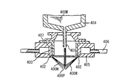
- FIG. 13 Another prior art shown in FIG. 13 is a spray nozzle 402 for spraying a high pressure fluid 400 W toward a falling flow of molten metal 400 M, as disclosed in JP-A 64-203 (Patent Document 3).
- the droplets of the molten metal adhere to the inner wall surface 407 by forming the inner wall surface 407 surrounding the falling flow with a material having a wettability of 90 ° to 180 ° with respect to the molten metal 400M. To prevent metal powder production.
- the surface of the inner wall surface 407 is rough and has fine unevenness, and a region where the contact angle is less than 90 ° locally occurs, and the molten metal 400M adheres and deposits on such a region, Over time, events often develop into blocking phenomena.
- Still another prior art shown in FIG. 14 is a coating layer made of a specific refractory material on the surface of the water jet nozzle 505 or its protection guide 506 disclosed in Japanese Patent Laid-Open No. 5-9513 (Patent Document 4).
- Patent Document 4 This is a method of preventing the adhesion blocking (blocking phenomenon) of the molten metal droplets by cooling the water jet nozzle 505 or its protection guide 506 by configuring the water nozzle 507.
- the covering layer 507 is made of a refractory material containing one or more of Si 3 N 4 , BN, or AlN, and having a porosity of 5% by volume or more. Molten metal does not adhere because 3 N 4 , BN or AlN decomposes. Further, by cooling the water jet nozzle 505 or its protection guide 506 from the inside by the cooling water 514, the coating layer 507 is kept at a low temperature, and the decomposition of the coating layer 507 due to the temperature rise is reduced.
- This technique is useful in preventing adhesion of molten metal to the water injection nozzle 505 and preventing blocking phenomenon.
- the coating layer 507 is locally decomposed due to the collision of droplets of molten metal, impurities derived from the coating layer 507 are mixed in the metal powder to be produced. That is, since the purity of the metal powder to be produced is low, there is a disadvantage that it can not be used as a raw material for high conductivity conductive paste in the field of electronics.
- the molten metal flows down from the melt nozzle in the form of a molten metal column.
- the inventor of the present invention is effective to keep the dynamic viscosity of the molten metal small in order to prevent clogging in the molten metal nozzle hole or to prevent the blocking phenomenon caused by the swing of the molten metal flowing down. I found it to be.
- FIG. 15 What is shown in FIG. 15 is a water atomizing method disclosed in Japanese Patent Application Laid-Open No. 8-143914 (Patent Document 5), in which the amount of S added to the molten metal is changed according to the water temperature of high pressure water to be sprayed. It is an apparatus.
- the apparatus includes a molten metal dropping means 601, a spray nozzle 603 for spraying high pressure water, a powder recovery chamber 605, a recovery pump 611, a cooling tank 609, a cooling tower 613, a recirculation pump 615, and a water temperature gauge 617. And a temperature display device 619.
- the temperature of the high pressure water sprayed rises with time and the viscosity decreases.
- the viscosity of the molten metal is lowered by reducing the amount of S added to the molten metal, and the balance with the decrease in viscosity accompanying the rise in the water temperature of the spray water is maintained. Powder can be produced.
- Patent Document 5 The idea of adjusting the viscosity of the molten metal disclosed in Patent Document 5 is also effective in preventing clogging of the molten metal nozzle hole and in preventing blocking phenomenon caused by the swing of the molten metal flowing down.
- the viscosity of the molten metal of metal is adjusted by adjusting the addition amount of S, it is inevitable that impurities are mixed in the metal powder to be manufactured. That is, there is a disadvantage that the purity of the metal powder to be produced is low and it can not be used as a raw material for high conductivity conductive paste etc. in the electronics field.
- JP 2007-291454 A Japanese Patent Application Laid-Open No. 62-151503 JP-A 64-203 JP-A-5-9513 JP-A-8-143914
- the metal powder manufacturing apparatus disclosed in Patent Document 1 has a path changing means for changing the path of the spray water after colliding with the molten metal column, and can obtain metal powder in which amorphization has progressed. It is not possible to obtain a crystallized metal powder suitable for a raw material such as a conductive paste of high conductivity in the field. Further, in the configuration of the conventional annular spray nozzle disclosed in Patent Document 1, it is difficult to attenuate circumferential disturbances or temporal fluctuations generated in the liquid jet, and the water is sprayed stably without interruption all around uniformly. It is difficult to do.
- the method for producing metal powder disclosed in Patent Document 2 intends to prevent adhesion of metal powder to the wall surface by flowing an adhesion preventing fluid along the wall surface on the upper side from the spray outlet of the spray nozzle. However, it is impossible to prevent seizure when the adhesion preventing fluid is blown away by air flow and the wall surface is exposed or when a large amount of molten metal touches and contacts the wall surface.
- the inner wall surface of the spray nozzle is made of a material having a wettability such that the contact angle with the molten metal is 90 ° to 180 °, so that the molten metal splashes.
- the method for preventing blocking phenomenon disclosed in Patent Document 4 comprises forming a coating layer made of a refractory material that decomposes when droplets of molten metal come in contact with the surface of a water jet nozzle or the like, and further cooling the water jet nozzle or the like.
- the purpose is to prevent the sticking and blocking (blocking phenomenon) of droplets of molten metal, but the conductive metal in the field of electronics has high conductivity because the metal powder produced is mixed with the impurities derived from the coating layer. It is not possible to obtain high purity metal powder suitable for raw materials such as organic pastes.
- the viscosity of the molten metal of metal is adjusted by adjusting the amount of addition of S according to the water temperature of the spray water to obtain a metal powder of stable quality.
- S is added to the molten metal, it is inevitable that impurities are mixed in the metal powder to be produced, and high purity suitable for raw materials such as high conductivity conductive pastes in the electronics field. There is a disadvantage that metal powder can not be obtained.
- the object of the present invention is to achieve high production efficiency and prevent clogging of molten metal nozzle holes and blocking phenomenon, so stable operation for a long time is possible, and high purity suitable for raw materials such as conductive paste of high conductivity in the electronics field. It is an object of the present invention to provide a silver powder production method and a silver powder production apparatus capable of obtaining silver powder of
- the present invention has been made to solve the above-mentioned problems, and in the first aspect of the present invention, molten silver is caused to flow down in a state of molten silver column, and the molten silver column is disposed so as to be a central axis.
- a method of producing a silver powder comprising at least a step of atomizing water onto the molten silver column from an annular spray nozzle to atomize the molten silver, the water being the top along a substantially inverted conical surface
- Melting the silver of the molten silver Column Tsu was micronized, and / or a silver powder manufacturing method characterized by further pulverizing into fine particles by the silver particles produced by atomization
- the water is allowed to travel from the outer edge side toward the inner edge side, with the gap sandwiched by the two annular surfaces curved upward toward the inner edge side as a flow path.
- the water is continuously sprayed along the substantially inverted conical surface by being applied downward to the annular reflecting surface, and the distance between the two annular surfaces defining the gap is on the inner edge side.
- the method of producing silver powder decreases toward the
- the diameter and the length of the suction pipe are set to be positioned.
- a hard carbon thin film is formed on the surface of the spray nozzle facing the molten silver column, the surface facing the molten silver flowing down, and the hard carbon thin film is a diamond thin film or DLC It is a film, and a water film is further formed by flowing water on the surface of the hard carbon thin film, thereby preventing silver from adhering to the hard carbon thin film and blocking phenomenon.
- the kinetic viscosity of the molten silver is 0.22 mm 2 / s or less by causing the molten silver to flow down from the melt nozzle and setting the temperature of the molten silver to 1400 ° C. or more and 1600 ° C. or less.
- the clogging of the melt nozzle and the blocking phenomenon are prevented, and the particle size of the produced silver powder is reduced.
- the diameter of the molten metal nozzle hole is 1 mm or more and 3 mm or less, and the average mass flow rate at which the molten silver flows down is 0.5 kg / min or more and 4.5 kg / min or less It is a silver powder manufacturing method in which the particle diameter of silver powder manufactured becomes small, so that the diameter of a nozzle hole is small.
- the material of the molten metal nozzle is any of aluminum nitride, silicon nitride, boron nitride, silicon carbide, magnesium oxide and aluminum oxide, preferably aluminum nitride or silicon nitride, and more preferably Is a method of producing silver powder which is silicon nitride.
- the eighth aspect of the present invention has a deionization step for producing deionized water from water, and produces silver powder to increase the purity of silver powder produced by spraying deionized water as the water. It is a method.
- a molten metal nozzle for causing molten silver to flow down in the form of molten silver columns, and water are sprayed along a substantially inverted conical surface so as to converge on a first convergent portion which is the top thereof.
- An apparatus for producing silver powder comprising: at least a spray nozzle for setting the position of the top portion inside the molten silver column; the spray nozzle having an axisymmetric suction pipe; As for the diameter and length of the water, the sprayed water atomizes the molten silver in the first convergence portion, the water having passed through the first convergence portion travels along a substantially conical surface, and the inner surface of the suction pipe
- the silver powder manufacturing apparatus is characterized in that it is set so as to strike and reflect on the first annular portion and to advance toward the second convergent portion which is the top thereof along the second substantially inverted conical surface.
- the spray nozzle comprises an upper annular member and a lower annular member facing each other at a distance, and the water is formed by using a gap between the two annular members as a flow passage.
- the upper surface of the lower annular member which advances from the outer edge side to the inner edge side and faces each other, and the lower surface of the upper annular member except for the innermost edge, both curve upward toward the inner edge at least at their inner edge.
- the eleventh aspect of the present invention 25 ° ⁇ ⁇ ⁇ 30 ° is satisfied, where ⁇ is the apex angle of the substantially inverted conical surface, and the second convergent portion is located above the lower end of the suction pipe. It is a silver powder manufacturing apparatus in which the diameter and the length of the suction pipe are set so as to be positioned.
- the twelfth aspect of the present invention is the surface of the spray nozzle facing the molten silver column, the surface facing the molten silver flowing down is coated with a hard carbon thin film, and the hard carbon thin film is a diamond thin film or DLC
- the film is a film, and the surface of the hard carbon thin film is coated with a water film by flowing water to prevent silver from adhering to the hard carbon thin film and blocking phenomenon.
- the thirteenth aspect of the present invention at least includes a heating means for heating silver to form molten silver, and a temperature control means for adjusting the temperature of the molten silver, wherein the temperature of the molten silver is 1400 ° C.
- a heating means for heating silver to form molten silver and a temperature control means for adjusting the temperature of the molten silver, wherein the temperature of the molten silver is 1400 ° C.
- the diameter of the molten metal nozzle hole is 1 mm or more and 3 mm or less, and the average mass flow rate at which the molten silver flows down is 0.5 kg / min or more and 4.5 kg / min or less It is a silver powder manufacturing device in which the particle diameter of silver powder manufactured becomes small, so that the diameter of a nozzle hole is small.
- the material of the molten metal nozzle is any of aluminum nitride, silicon nitride, boron nitride, silicon carbide, magnesium oxide and aluminum oxide, preferably aluminum nitride or silicon nitride, more preferably Is a silver powder manufacturing apparatus which is silicon nitride.
- the sixteenth embodiment of the present invention has a deionization apparatus for producing deionized water from water, and produces silver powder to increase the purity of silver powder produced by spraying deionized water as the water. It is an apparatus.
- the first aspect of the present invention it is possible to provide a silver powder production method capable of efficiently producing silver powder by micronizing molten silver at two places.
- the water is sprayed from the annular spray nozzle disposed so that the molten silver column is at the central axis so as to converge to the first convergent portion which is the top along the substantially inverted conical surface.
- the molten silver is micronized in the first convergence portion, and the water having passed through the first convergence portion travels along a substantially conical surface and is reflected on the first annular portion of the inner surface of the axisymmetric suction pipe,
- the molten silver of the molten silver column which proceeds along a second substantially inverted conical surface so as to converge to a second convergent portion which is the top thereof, and is not refined in the first convergent portion in the second convergent portion
- the water after the water is advanced from the outer edge side toward the inner edge side, with the gap sandwiched by the two annular surfaces curved upward toward the inner edge side as a flow path , And reflects downward toward the toroidal reflecting surface, and the distance between the two toroidal surfaces defining the gap decreases toward the inner edge side, so that the water may be all along the substantially inverted conical surface. It can spray without a break.
- the present inventors have found that water can be sprayed substantially uniformly without interruption around the entire circumference by adopting a configuration in which water is once applied to the annular reflecting surface and reflected downward. The reason is not clear, but the circumferential non-uniformity of the velocity of water as it rises diagonally upward against the gravity between the two annular surfaces whose distance decreases toward the inner edge side Components and time-varying components are attenuated, and when water strikes the toroidal reflecting surface, circumferential non-uniformity and temporal variation of the velocity of water are averaged and equalized, I think that I can spray almost uniformly all around the circumference.
- the molten silver since the size ⁇ of the apex angle of the substantially inverse conical surface is set to a small angle satisfying 25 ° ⁇ ⁇ ⁇ 30 °, the molten silver receives the impact of the spray water. Since a blocking phenomenon caused by blowing up is unlikely to occur, and the molten silver is pulverized at two points of the first convergent part and the second convergent part to make the molten silver into fine particles, a silver powder manufacturing method with high production efficiency Can be provided.
- the shape (diameter and length) of the suction pipe is set so that the second convergent portion is positioned above the lower end of the suction pipe, turbulence in the suctioned air flow is less likely to occur in the suction pipe. It is possible to suppress the occurrence of the blocking phenomenon caused by the swing of the spray water and the swing of the molten silver column.
- the shape (diameter and length) of the suction pipe is such that the water passing through the second convergent portion advances along the second substantially conical surface, and the second annular ring of the inner surface of the suction pipe Since the suction air flow is set so as not to occur in the suction pipe, it is possible to prevent the occurrence of the blocking phenomenon caused by the swing of the spray water and the swing of the molten silver column more reliably.
- a hard carbon thin film is formed on the surface facing the molten silver column of the spray nozzle and facing the molten silver flowing down, and the hard carbon thin film is a diamond thin film or a DLC film Further, since a water film is formed by flowing water on the surface of the hard carbon thin film, it is possible to provide a silver powder production method for preventing the adhesion of silver to the hard carbon thin film and the blocking phenomenon.
- the contact angle between the hard carbon thin film and the molten silver is in the range of 90 ° to 180 °, the hard carbon thin film has the property of not wetting to the molten silver.
- a hard carbon thin film can be formed on the surface of the spray nozzle by a method such as CVD, PVD, plating, or sputtering, and the surface can be formed microscopically flat, molten silver droplets are in contact However, adhesion and deposition are unlikely to occur.
- the dynamic viscosity of the molten silver is reduced to 0.22 mm 2 / s or less. It is possible to provide a silver powder manufacturing method which realizes smooth outflow of molten silver, prevents clogging of the molten metal nozzle holes and blocking phenomenon, and reduces the particle size of the manufactured silver powder.
- the temperature of the molten silver may be any temperature within the range of the melting point of silver (962 ° C.) to 1600 ° C., but the range of 1400 ° C. to 1600 ° C. is preferable for atomization without causing the blocking phenomenon. This is because if the temperature of molten silver is less than 1300 ° C., regardless of the material of the molten metal nozzle, the molten metal of silver does not flow out smoothly from the molten metal nozzle hole, so the above temperature is preferably 1300 ° C. or higher, Furthermore, in order to prevent clogging and blocking phenomenon of the molten metal nozzle hole, a temperature of 1400 ° C.
- the diameter of the molten metal nozzle hole is 1 mm or more and 3 mm or less
- the average mass flow rate at which the molten silver flows down is 0.5 kg / min or more and 4.5 kg / min or less
- the molten silver can be efficiently crushed at two places of the first convergent part and the second convergent part by spray water and silver powder can be manufactured, the apex angle of the substantially reverse conical surface to prevent the blocking phenomenon. If the diameter of the molten metal nozzle hole is set within the above range and the molten silver is made to flow down at a relatively large average mass flow of 0.5 kg / min or more and 4.5 kg / min or less, even if A large amount of silver powder can be produced. Moreover, the average particle diameter of the silver powder manufactured can be made small by selecting the diameter of a smaller molten metal nozzle hole within the said range.
- the material of the molten metal nozzle is any of aluminum nitride, silicon nitride, boron nitride, silicon carbide, magnesium oxide and aluminum oxide, preferably aluminum nitride or silicon nitride, and further, A method of producing silver powder, preferably silicon nitride, can be provided.
- the molten metal nozzle In order to prevent clogging of the molten silver in the molten metal nozzle hole, it is desirable to form the molten metal nozzle with a material having a large thermal conductivity. Therefore, aluminum nitride having the highest thermal conductivity is desired as the ceramic nozzle material. However, aluminum nitride has the disadvantage of brittle fracture during use due to the inherent thermal expansion of wurtzite crystals. Therefore, silicon nitride, which has high thermal conductivity and does not cause brittle fracture, is suitable as a nozzle material. In addition, silicon carbide, boron nitride, aluminum oxide, magnesium oxide or the like may be used as the material of the molten metal nozzle.
- a silver which has a deionization step for producing deionized water from water, and raises the purity of silver powder produced by spraying deionized water as the water. It is possible to provide a powder production method. According to the manufacturing method of the present embodiment, it is possible to manufacture a silver powder which has few impurities and is suitable for use in the field of electronics.
- high production is achieved by atomizing water from the spray nozzle onto the flowing down molten silver column and atomizing the molten silver at two points of the first convergence portion and the second convergence portion.
- An apparatus for producing silver powder capable of efficiently producing silver powder can be provided.
- the tenth aspect of the present invention after the water is advanced from the outer edge side toward the inner edge side, with the gap sandwiched by the two annular surfaces curved upward toward the inner edge side as a flow path The water is applied to the toroidal reflecting surface and reflected downward, and the distance between the two toroidal surfaces defining the gap is reduced toward the inner edge, thereby using the water It is possible to provide a silver powder production apparatus which sprays without interruption all around along the substantially inverted conical surface and suppresses the occurrence of blocking phenomenon due to the fluctuation of the molten silver column and the disturbance of the suction air flow.
- the size ⁇ of the apex angle of the substantially inverse conical surface is set to a small angle satisfying 25 ° ⁇ ⁇ ⁇ 30 °, a blocking phenomenon is less likely to occur, and molten silver Can be pulverized at two points of the first convergent part and the second convergent part to efficiently atomize the molten silver, so it is possible to provide a silver powder production apparatus with high production efficiency.
- the shape (diameter and length) of the suction pipe is set so that the second convergent portion is positioned above the lower end of the suction pipe, turbulence in the suctioned air flow is less likely to occur in the suction pipe. And the occurrence of blocking phenomenon can be suppressed.
- the shape (diameter and length) of the suction pipe is such that the water passing through the second converging portion travels along the second substantially conical surface and hits the second annular portion of the inner surface of the suction pipe Since the setting is made as described above, the disturbance of the suction air flow is less likely to occur in the suction pipe, and the occurrence of the blocking phenomenon can be prevented more reliably.
- a hard carbon thin film is formed on the surface facing the molten silver column of the spray nozzle and facing the flowing molten silver, and the hard carbon thin film is a diamond thin film or a DLC film Further, since a water film is formed by flowing water on the surface of the hard carbon thin film, it is possible to provide a silver powder production apparatus which prevents the adhesion of silver to the hard carbon thin film and the blocking phenomenon.
- the temperature of the molten silver by setting the temperature of the molten silver to 1400 ° C. or more and 1600 ° C. or less, the dynamic viscosity of the molten silver is reduced to 0.22 mm 2 / s or less, and clogging of the molten metal nozzle hole is caused. It is possible to provide a silver powder production apparatus which prevents the blocking phenomenon and reduces the particle size of the produced silver powder.
- the diameter of the molten metal nozzle hole is 1 mm or more and 3 mm or less
- the average mass flow rate at which the molten silver flows down is 0.5 kg / min or more and 4.5 kg / min or less
- a silver powder manufacturing apparatus which prevents clogging of a molten metal nozzle hole by using a material having high thermal conductivity and / or which is unlikely to cause brittle fracture as a molten metal nozzle. it can.
- deionized water as the water to be sprayed, it is possible to provide a silver powder production apparatus which produces silver powder suitable for use in the electronics field with few impurities.
- pure water or ultrapure water such as distilled water or RO water may be used instead of deionized water depending on the required purity of the silver powder and requirements of the production cost.
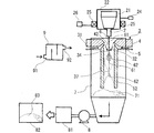
- FIG. 1 is an overall conceptual view showing one embodiment of a silver powder production apparatus of the present invention
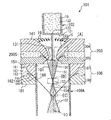
- FIG. 2 is a cross-sectional view of a spray nozzle 3 in the present embodiment.
- a graphite crucible 21 is disposed in a tundish furnace 22 provided with heating means 2 ⁇ BR> T and a temperature control means 26, and silver in the graphite crucible 21 is heated by the heating means 25 to become molten silver 6, and the graphite crucible From the molten metal nozzle 2 attached to 21, it flows down in the state of molten silver column 61.
- the water having passed through the first converging portion 34 travels along the substantially conical surface 35, is reflected by the first annular portion 53 of the inner surface of the axisymmetric suction pipe 52, and converges to the second converging portion 37. Advance along a second generally inverse conical surface 36.
- the water micronizes the molten silver 6 which has not been micronized in the first converging section 34, and / or further micronizes the silver particles 62 micronized in the first converging section 34, Silver particles 62 are formed.
- the suction pipe 52 is sufficiently long, the water having passed through the second convergent portion 37 travels along the second substantially conical surface 38 and hits the second annular portion 54 of the inner surface of the axisymmetric suction pipe 52. .
- the generated silver particles 61 are deposited together with the water.
- the deposited silver particles 71 are transported to the filter means 81 together with the water by the suction and delivery action of the pump 8.
- the filter means 81 the water and the silver particles 61 are separated.
- the separated silver particles 61 are dried by a dryer 82 to obtain silver powder 83.
- the water sprayed from the spray nozzle 3 is deionized water to produce a silver powder of high purity.
- the silver powder production device 1 has a deionization device 9, which has an industrial water inlet 91 and a deionized water outlet 92. When water such as industrial water passes through the deionization device 9, it is deionized to be deionized water. Water such as industrial water is supplied to the deionized water inlet 91, and the deionized water flowing out from the deionized water outlet 92 is guided to the spray nozzle 3 as high-pressure water under pressure.
- the silver powder production storage 1 includes horizontal position adjusting means 24 for adjusting the horizontal position of the molten silver column 61. Since the first convergent portion 34 which is the top of the substantially inverted conical surface 33 can be set inside the molten silver column 6 by the horizontal position adjusting means 24, the molten silver 6 of the molten silver column 61 becomes the first convergent portion At 34, the silver particles 62 are efficiently crushed to form silver particles 62, and the axial symmetry of the traveling path of the water passing through the first converging portion 34 is ensured, and most of the water is along the substantially conical surface 35. After being advanced, the light can be reflected by the first annular portion 53, further advanced along the second substantially inverted conical surface 36, and collided with the molten silver column 61 again at the second convergent portion 37.
- the spray nozzle 3 has an annular slit (gap 31) through which water travels.
- the spray nozzle 3 has the upper annular member 4 and the lower annular member 5 opposed to each other with the gap 31 therebetween, and water is used as the flow channel in the direction of the arrow 32 indicating the advancing direction of water. It progresses toward the inner edge side from the outer edge side.
- the lower surface of the upper annular member 4 includes a curved upper annular surface 41
- the upper surface of the lower annular member 5 includes a curved lower annular surface 51, the upper annular surface 41 and the lower annular surface facing each other The interval of 51 is narrower toward the inner edge.
- the innermost edge of the lower surface of the upper annular member 4 is an annular reflecting surface 42 connected to the upper edge of the upper annular surface 41 without any step.
- the water which travels from the outer edge side to the inner edge side in the gap 31, is applied to the annular reflecting surface 42 and reflected downward, so that the water is a first converging portion along the substantially reverse conical surface 33. It is sprayed almost uniformly all around without interruption all around so that it converges to 34.
- the lower annular member 5 has an axisymmetric suction pipe 52 at its lower part, and the inner surface of the suction pipe 52 is smoothly connected to the inner surface of the lower annular member 5 excluding the suction pipe 52 without any step. Therefore, generation
- the shape of the inner surface of the suction tube 52 is not limited to a straight cylinder.
- the inner surface generally has the shape of a rotating surface obtained by rotating a smooth curve around an axis.
- the shape of the suction tube 52 is selected such that the first annular portion 53 to which the water passing through the first converging portion 34 is reflected is present on the inner surface of the suction tube 52.
- the molten silver 6 and / or the silver particles 62 can be made into fine particles again not only in the first converging portion 34 but also in the second converging portion 37, so a large amount of silver particles can be obtained in a short time. Can be generated efficiently.
- the inner diameter of the suction pipe 52 is D
- the length of the suction pipe 52 (more precisely, the suction pipe Assuming that the distance to the lower end of 52 is L, and the size of the apex angle of the substantially inverted conical surface 33 is ⁇ , the following equation 1 is established.
- the shape of the suction tube 52 is selected such that the second convergent portion 37 is located above the lowermost end of the suction tube 52.
- the shape of the suction tube 52 is selected such that the second annular portion 54 to which the water passed through the second converging portion 37 is reflected is present on the inner surface of the suction tube 52.
- the molten silver 6 can be efficiently micronized at two points, the first convergence portion and the second convergence portion.
- the diameter and the length of the suction pipe 52 satisfy the relationship L / D ⁇ 7. It is preferable to set as follows.
- the angle ⁇ formed by the water sprayed from the spray nozzle 3 that is, the apex angle ⁇ of the substantially inverted conical surface 33 to 30 ° or less, the suction force caused by the suction air flow caused by the sprayed water becomes strong, and the spray nozzle 3. It is possible to suppress adhesion and deposition of the silver particles 62 and the molten silver 6 to 3 and the particle size of the produced silver powder 83 is reduced.
- the angle ⁇ is usually in the range of 25 ° to 30 °.
- the preferable range of the angle ⁇ varies depending on the diameter of the spray nozzle 3, the spray pressure, the volumetric flow rate of water to be sprayed, and the like, and is not necessarily limited to the above range.
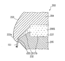
- FIG. 3 shows a hard carbon thin film 43 formed on the upper surface of the upper annular member 43 facing the molten silver column 61 in one embodiment of the present invention, and water is further flowed on the hard carbon thin film 43; It is sectional drawing of the spray nozzle 3 which formed the water film 44 by running water. The water sprayed from the spray nozzle 3 along the substantially inverted conical surface 33 atomizes the molten silver 6 of the molten silver column 61 in the first convergence portion 34 to generate silver particles 62.
- the hard carbon thin film 43 and the water film 44 by the flowing water prevent the droplets of the silver particles 62 and the molten silver 6 from adhering and depositing on the surface of the upper surface of the spray nozzle 3 facing the molten silver columns 61 to cause a blocking phenomenon. . Therefore, silver powder 83 can be manufactured stably in the present embodiment.
- the hard carbon thin film 43 is a diamond thin film or a DLC film, both of which are materials that do not react chemically with silver.
- the formation of the water film 44 by the flowing water is an operation performed to prevent adhesion and deposition of silver on the spray nozzle 3, but the formation of the hard carbon thin film 43 makes the effect more effective.
- the hard carbon thin film 43 is formed on the surface of the spray nozzle 3 using a method such as CVD, PVD, plating, or sputtering.
- the thickness of the hard carbon thin film 43 and the thickness of the water film 44 due to flowing water are not limited as long as the blocking phenomenon can be prevented.
- the thickness of the hard carbon thin film 43 preferable to prevent the blocking phenomenon and the thickness of the water film 44 by the preferable flowing water are the volumetric flow rate of water sprayed from the spray nozzle 3 and the average mass flow rate of the molten silver 6 flowing down. It depends on the apex angle ⁇ of the substantially inverted conical surface 33, the shape (diameter and length) of the suction pipe 52, and the like, and in particular, the volume flow rate of water sprayed from the spray nozzle 3.
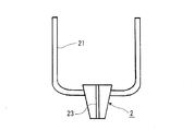
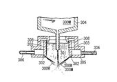
- FIG. 4 shows a graphite crucible 21 according to an embodiment of the present invention, a melt nozzle 2 attached thereto, and a melt nozzle hole 23 penetrating the melt nozzle 2.
- the molten silver 6 in the graphite crucible 21 flows through the molten metal nozzle hole 23 of the molten metal nozzle 2 in the state of the molten silver column 61.
- a high frequency induction heating furnace has been used as a tundish furnace 22 equipped with heating means 24, and a graphite crucible and a nozzle made of graphite have been used there.
- the thermal conductivity of graphite is very high at 80 W / (m ⁇ K) to 140 W / (m ⁇ K)
- graphite has the disadvantage of being brittle.
- the diameter of the molten metal nozzle hole 23 may be increased.
- the material of the molten metal nozzle 2 is any of aluminum nitride, silicon nitride, boron nitride, silicon carbide, magnesium oxide and aluminum oxide, more preferably aluminum nitride or silicon nitride, more preferably
- silicon nitride By using silicon nitride, it is possible to prevent the clogging of silver at the molten metal nozzle hole 23 and to manufacture a stable silver powder.
- Aluminum nitride and silicon nitride, which have high thermal conductivity, are suitable as the material of the melt nozzle 2, and among them, silicon nitride, in which brittle fracture does not occur, is particularly suitable as the material of the melt nozzle 2.
- the diameter of the molten metal nozzle hole 23 is in the range of 1 mm to 3 mm. The smaller the diameter is, the smaller the particle size of the produced silver powder 83 is.
- silver powder 83 of high purity can be produced.
- the water film 44 by the flowing water is deionized water from the viewpoint of increasing the purity of the silver powder 83. It is preferable to form by flowing.
- Example 1 40 kg of silver lumps were filled in a graphite crucible 21 in a high frequency melting furnace 22 and melted by raising the temperature to 1370 ° C. in a nitrogen atmosphere. After melting, water was sprayed using an annular spray nozzle 3 provided with a diamond thin film 43 and a water film 44 by flowing water while allowing the molten silver to flow down from the molten silicon nozzle 2 of silicon nitride.
- the spray pressure of water was 80 MPa, and the volumetric flow rate was 220 L / min.
- the said water and running water used deionized water.
- the diameter of the molten metal nozzle hole 23 was 1.8 mm, the average mass flow rate of the flowing down molten silver 6 was 2 kg / min, the suction pipe 52 was a straight cylindrical shape, the inner diameter D was 3 cm, and the length L was 25 cm.
- Silver is pulverized by spraying water from the spray nozzle 3 to form silver particles 62, and the silver particles 62 are generated and stored in the water tank 7, then filtered by the filter press 81 and dried at 60 ° C. in the dryer 82.
- FIG. 5 is a SEM image (JEOL JSM-6510) of silver powder 83 obtained in Example 1, and FIG. 6 similarly shows a particle size distribution (Nikkiso MT3300EXII). From the SEM image, the silver powder 83 contains particles in the shape of spheres, ovals, crushed particles, and the like. From the particle size distribution, the volume-based average particle diameter was 8.2 ⁇ m, and the number-based average particle diameter was 2.5 ⁇ m.
- FIG. 7 is a powder X-ray diffraction diagram (Shimazu XRD-6100) of the silver powder 83 obtained in Example 1.
- a CuK ⁇ ray was used as the X-ray source, and the applied voltage and applied current were 40 kV and 30 mA, respectively, and a range of 30 ° to 90 ° in 2 ⁇ was measured at a step width of 0.02 °.
- the crystallite size determined from the Debye-Scheller equation (Equation 4) was 18.4 nm.
- K is a form factor
- ⁇ is an X-ray wavelength
- ⁇ is a full width at half maximum
- ⁇ is a Bragg angle
- ⁇ is a size of a crystallite.
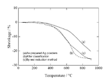
- FIG. 8 is a contraction curve of the silver paste using the silver powder 83 obtained in Example 1 as a raw material by thermomechanical analysis (RIGAK TMA 8310).
- Silver powder was prepared by mixing silver powder 83 with a vehicle in which ethyl cellulose was dissolved in butyl carbitol acetate.
- the mixing ratio of silver powder 83, ethyl cellulose and butyl carbitol acetate was 85 wt%: 2 wt%: 13 wt% by weight.
- the viscosity of the silver paste at this time was about 200 Pa ⁇ s.
- the silver paste was coated on a PET film with a doctor blade to a film thickness of about 250 ⁇ m and then dried at 100 ° C. for 2 hours.
- the film was peeled off from the PET film, cut into a 13 mm ⁇ disk shape, the sample was heated, and the temperature was raised to 900 ° C. at a temperature rising rate of 5 ° C./min.
- A) and (b) are the results according to the present invention, and the silver powder according to (b) uses a classifier to reduce the particle size of silver powder 83 of (a) to 2.5 ⁇ m or less, and (c) of It is almost the same as the particle size.
- (C) is the result of the silver powder manufactured by the wet reduction method.
- the contraction rate of (a) is smaller than that of (c) because the silver powder of (a) contains coarse particles.
- Table 1 shows the content of impurities contained in the silver powder 83 obtained in Example 1 in comparison with two comparative samples.
- the silver powder 83 was dissolved in dilute nitric acid, diluted to 100 ppm, and measured by an ICP emission spectrophotometer (Horiba ULTIMA 2).
- Comparative sample 1 is a silver powder produced by water atomization using private water (industrial water) as it is.
- Comparative sample 2 is a silver powder produced by a wet reduction method.
- the silver powder 83 of Example 1 contains less impurities than Comparative Sample 1 and Comparative Sample 2, and is suitable for use in the electronics field.
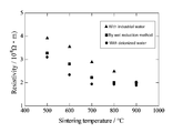
- FIG. 8 shows how the electrical resistivity after sintering of the silver paste using the silver powder 83 obtained in Example 1 as a raw material changes depending on the sintering temperature, in contrast to two comparative samples.
- Silver powder was prepared by mixing silver powder 83 with a vehicle in which ethyl cellulose was dissolved in butyl carbitol acetate.
- the mixing ratio of silver powder 83, ethyl cellulose and butyl carbitol acetate was 85 wt%: 2 wt%: 13 wt% by weight.
- the viscosity of the silver paste at this time was about 200 Pa ⁇ s.
- the silver paste was coated on a PET film with a doctor blade to a film thickness of about 250 ⁇ m and then dried at 100 ° C. for 2 hours.
- the film was peeled off from the PET film and cut into a 13 mm ⁇ disk to prepare five samples. Each sample was heated and heated up to 500 ° C., 600 ° C., 700 ° C., 800 ° C., or 900 ° C. at a heating rate of 5 ° C./min. After cooling to room temperature, a platinum electrode was attached to each sample and the specific resistance was measured with a multimeter (Mitsubishi Chemical MCP-T360).
- the circle marks show the results according to Example 1 of the present invention
- the triangle marks show the results of silver powder atomized with private water (industrial water)
- the square marks show the results of silver powder produced by the wet reduction method. Since the silver powder 83 of the present invention has a low impurity content, the sample after sintering exhibits the lowest electrical resistivity at any sintering temperature, and is suitable for use in the electronics field.
- Table 2 shows the presence or absence of occurrence of clogging of silver due to the material of the molten metal nozzle 2.
- Graphite, alumina and silicon nitride were used as the material of the molten metal nozzle 2.
- 25 kg of silver was dissolved at 1370 ° C., and water atomization was performed by spraying water having a pressure of 80 MPa and a volumetric flow rate of 220 L / min.
- the average mass flow rate of the flowing down molten silver 6 was 2 kg / min, and the diameter of the molten metal nozzle hole 23 was 1.8 mm.
- the impurities of the graphite crucible 21 are deposited on the nozzle during 25 kg of silver atomization to cause clogging of the molten metal nozzle hole 23.
- silicon nitride clogging does not occur even if 40 kg of silver is atomized.
- Silicon nitride is most excellent in toughness at high temperature and thermal shock resistance, and has a small thermal expansion coefficient. Therefore, the molten metal nozzle 2 made of silicon nitride is most reliable against temperature change during atomization.
- Table 3 shows how the presence or absence of the occurrence of the blocking phenomenon in the spray nozzle 3 changes depending on the angle (apex angle ⁇ ) of the water to be sprayed.
- Alumina was used for the molten metal nozzle 2. 25 kg of silver was melted at 1370 ° C., molten silver was made to flow at an average mass flow of 2 kg / min, and atomized by spraying water having a pressure of 80 MPa and a volumetric flow of 220 L / min.
- a straight cylindrical suction pipe 52 having an inner diameter D of 3 cm and a length L of 25 cm was used.
- the apex angle ⁇ By reducing the apex angle ⁇ , the droplets of molten silver are less likely to be scattered upward, and due to the suction force of the suction air flow, the adhesion of silver to the spray nozzle 3 is less likely to occur. In addition, when the apex angle ⁇ is reduced, the grinding of the molten silver is promoted, and the particle size of the produced silver powder becomes slightly smaller.
- Example 4 shows how the presence or absence of the occurrence of the blocking phenomenon in the spray nozzle 3 changes depending on the shape of the suction pipe 52 (ratio L / D of length).
- the melt nozzle 2 was made of alumina, and the diameter of the melt nozzle hole was 1.8 mm. 25 kg of silver was melted at 1370 ° C., molten silver was made to flow at an average mass flow of 2 kg / min, and atomized by spraying water having a pressure of 80 MPa and a volumetric flow of 220 L / min.
- the apex angle ⁇ was 25 °, and the inner diameter D of the straight cylindrical suction pipe 52 was 3 cm. As the length ratio L / D is larger, the disturbance of the suction air flow is reduced, so that the blocking phenomenon is less likely to occur.
- the silver powder produced by the water atomization method according to the present invention is high in purity and in progress of crystallization, and when used as a raw material of the conductive paste, exhibits high electric conductivity at a low sintering temperature. If used for electrode pastes, conductive pastes and inductors for solar cells, this will lead to improved reliability of energy saving devices and mobile devices. Moreover, since it is a manufacturing method with high production efficiency and capable of stable production for a long time, the production cost can be reduced.
- the silver powder production method and the new powder production apparatus of the present invention can be widely used in many industries related to the electronics field.
Landscapes
- Manufacture Of Metal Powder And Suspensions Thereof (AREA)
- Powder Metallurgy (AREA)
- Nozzles (AREA)
- Glanulating (AREA)
Applications Claiming Priority (2)
| Application Number | Priority Date | Filing Date | Title |
|---|---|---|---|
| JP2016168090A JP6817615B2 (ja) | 2016-08-30 | 2016-08-30 | 金属粉末製造方法及び金属粉末製造装置 |
| JP2016-168090 | 2016-08-30 |
Publications (1)
| Publication Number | Publication Date |
|---|---|
| WO2018042684A1 true WO2018042684A1 (ja) | 2018-03-08 |
Family
ID=61300372
Family Applications (1)
| Application Number | Title | Priority Date | Filing Date |
|---|---|---|---|
| PCT/JP2016/081286 Ceased WO2018042684A1 (ja) | 2016-08-30 | 2016-10-21 | 銀粉末製造方法及び銀粉末製造装置 |
Country Status (2)
| Country | Link |
|---|---|
| JP (1) | JP6817615B2 (enExample) |
| WO (1) | WO2018042684A1 (enExample) |
Cited By (4)
| Publication number | Priority date | Publication date | Assignee | Title |
|---|---|---|---|---|
| CN108941591A (zh) * | 2018-08-24 | 2018-12-07 | 连平县昕隆实业有限公司 | 一种水雾化喷嘴 |
| CN112475306A (zh) * | 2020-11-17 | 2021-03-12 | 江苏威拉里新材料科技有限公司 | 一种多功能的气雾化金属粉末床 |
| CN113059168A (zh) * | 2021-03-19 | 2021-07-02 | 山东金创金银冶炼有限公司 | 一种半成品贵金属液体提纯装置及其工艺 |
| CN113828785A (zh) * | 2021-10-14 | 2021-12-24 | 怀化辰州机械有限责任公司 | 一种锑熔液水萃成粒方法 |
Families Citing this family (6)
| Publication number | Priority date | Publication date | Assignee | Title |
|---|---|---|---|---|
| JP7131245B2 (ja) * | 2018-09-21 | 2022-09-06 | Tdk株式会社 | 金属粉末製造装置と金属粉末の製造方法 |
| JP7110867B2 (ja) * | 2018-09-21 | 2022-08-02 | Tdk株式会社 | 金属粉末製造装置と金属粉末の製造方法 |
| CN110538473B (zh) * | 2019-08-30 | 2021-10-08 | 厦门金达威维生素有限公司 | 一种雾化盘、喷雾干燥雾化器及其雾化高粘度物料的方法 |
| JP7266009B2 (ja) * | 2020-04-13 | 2023-04-27 | 東京窯業株式会社 | アトマイズ装置 |
| JP7470657B2 (ja) * | 2021-04-06 | 2024-04-18 | 東京窯業株式会社 | アトマイズ装置 |
| CN116586617A (zh) * | 2023-05-18 | 2023-08-15 | 贵州越达增材材料科技有限公司 | 一种3d打印用的银粉雾化装置及雾化方法 |
Citations (4)
| Publication number | Priority date | Publication date | Assignee | Title |
|---|---|---|---|---|
| JPH01123012A (ja) * | 1987-11-09 | 1989-05-16 | Kawasaki Steel Corp | 微粉製造用ノズル |
| JPH059513A (ja) * | 1991-07-09 | 1993-01-19 | Kawasaki Steel Corp | 流体噴射ノズルとその保護ガイドへの溶融金属の付着閉塞の防止方法 |
| JP2007291454A (ja) * | 2006-04-25 | 2007-11-08 | Seiko Epson Corp | 金属粉末製造装置、金属粉末および成形体 |
| CN101992301A (zh) * | 2010-12-06 | 2011-03-30 | 石家庄铁道大学 | 高压水雾化法生产球形不锈钢粉末材料的方法 |
-
2016
- 2016-08-30 JP JP2016168090A patent/JP6817615B2/ja active Active
- 2016-10-21 WO PCT/JP2016/081286 patent/WO2018042684A1/ja not_active Ceased
Patent Citations (4)
| Publication number | Priority date | Publication date | Assignee | Title |
|---|---|---|---|---|
| JPH01123012A (ja) * | 1987-11-09 | 1989-05-16 | Kawasaki Steel Corp | 微粉製造用ノズル |
| JPH059513A (ja) * | 1991-07-09 | 1993-01-19 | Kawasaki Steel Corp | 流体噴射ノズルとその保護ガイドへの溶融金属の付着閉塞の防止方法 |
| JP2007291454A (ja) * | 2006-04-25 | 2007-11-08 | Seiko Epson Corp | 金属粉末製造装置、金属粉末および成形体 |
| CN101992301A (zh) * | 2010-12-06 | 2011-03-30 | 石家庄铁道大学 | 高压水雾化法生产球形不锈钢粉末材料的方法 |
Cited By (4)
| Publication number | Priority date | Publication date | Assignee | Title |
|---|---|---|---|---|
| CN108941591A (zh) * | 2018-08-24 | 2018-12-07 | 连平县昕隆实业有限公司 | 一种水雾化喷嘴 |
| CN112475306A (zh) * | 2020-11-17 | 2021-03-12 | 江苏威拉里新材料科技有限公司 | 一种多功能的气雾化金属粉末床 |
| CN113059168A (zh) * | 2021-03-19 | 2021-07-02 | 山东金创金银冶炼有限公司 | 一种半成品贵金属液体提纯装置及其工艺 |
| CN113828785A (zh) * | 2021-10-14 | 2021-12-24 | 怀化辰州机械有限责任公司 | 一种锑熔液水萃成粒方法 |
Also Published As
| Publication number | Publication date |
|---|---|
| JP6817615B2 (ja) | 2021-01-20 |
| JP2018035388A (ja) | 2018-03-08 |
Similar Documents
| Publication | Publication Date | Title |
|---|---|---|
| WO2018042684A1 (ja) | 銀粉末製造方法及び銀粉末製造装置 | |
| US5445324A (en) | Pressurized feed-injection spray-forming apparatus | |
| CN111954581A (zh) | 由粗的且有棱角的粉末进料生产细的球状粉末的方法和装置 | |
| US11607732B2 (en) | High melting point metal or alloy powders atomization manufacturing processes | |
| EP3504020B1 (en) | Low melting point metal or alloy powders atomization manufacturing processes | |
| KR102521461B1 (ko) | 부정비 산화티탄 미립자의 제조 방법 | |
| RU2765190C1 (ru) | Устройство и способ получения сверхмелкого низкоплавкого сферического металлического порошка с применением капельного распыления | |
| JP5094668B2 (ja) | Ni−W系合金微粒子の製造方法並びにNi−W合金微粒子の製造方法 | |
| CN107414091B (zh) | 一种纳米陶瓷增强型钛合金粉末的制备系统及方法 | |
| KR20040067608A (ko) | 금속 분말 및 그 제조 방법 | |
| KR102883125B1 (ko) | 유체분사노즐 조립체 | |
| CN105817632A (zh) | 片状粉末的制备装置及方法 | |
| JP5228149B2 (ja) | 成膜用ノズルおよび成膜方法ならびに成膜部材 | |
| US20120156384A1 (en) | Pressure controlled droplet spraying (pcds) method for forming particles of compound materials from melts | |
| KR20180046652A (ko) | 금속 분말 제조를 위한 원추형 수분사 아토마이저 가변 노즐 | |
| CN111565870A (zh) | 铜微粒子 | |
| CN114589310A (zh) | 一种微米球形银粉制备方法 | |
| KR20190060495A (ko) | 진공 서스펜션 플라즈마 용사장치 및 진공 서스펜션 플라즈마 용사방법 | |
| KR102870458B1 (ko) | 분무조립체 및 이를 포함하는 금속분말 제조장치 | |
| JPS60500872A (ja) | 超微細金属粉末を製造する方法 | |
| TW202124068A (zh) | 微粒子 | |
| Wang et al. | Combination of spray forming and metal powder productions by the internal mixing atomizer with a substrate | |
| TW201916934A (zh) | 熔湯輸送導管及應用其之合金粉末製造設備 | |
| Pollak et al. | Production of spherical metallic powders dedicated to additive manufacturing | |
| Reddy et al. | Effect of cold rolling on microstructural properties of spray deposited Al-% 18Pb And Al-% 22Pb Alloys |
Legal Events
| Date | Code | Title | Description |
|---|---|---|---|
| 121 | Ep: the epo has been informed by wipo that ep was designated in this application |
Ref document number: 16915239 Country of ref document: EP Kind code of ref document: A1 |
|
| NENP | Non-entry into the national phase |
Ref country code: DE |
|
| 122 | Ep: pct application non-entry in european phase |
Ref document number: 16915239 Country of ref document: EP Kind code of ref document: A1 |