WO2018042684A1 - Silver powder production method and silver powder production apparatus - Google Patents
Silver powder production method and silver powder production apparatus Download PDFInfo
- Publication number
- WO2018042684A1 WO2018042684A1 PCT/JP2016/081286 JP2016081286W WO2018042684A1 WO 2018042684 A1 WO2018042684 A1 WO 2018042684A1 JP 2016081286 W JP2016081286 W JP 2016081286W WO 2018042684 A1 WO2018042684 A1 WO 2018042684A1
- Authority
- WO
- WIPO (PCT)
- Prior art keywords
- silver
- water
- molten
- silver powder
- molten metal
- Prior art date
Links
Images


Classifications
-
- B—PERFORMING OPERATIONS; TRANSPORTING
- B22—CASTING; POWDER METALLURGY
- B22F—WORKING METALLIC POWDER; MANUFACTURE OF ARTICLES FROM METALLIC POWDER; MAKING METALLIC POWDER; APPARATUS OR DEVICES SPECIALLY ADAPTED FOR METALLIC POWDER
- B22F1/00—Metallic powder; Treatment of metallic powder, e.g. to facilitate working or to improve properties
-
- B—PERFORMING OPERATIONS; TRANSPORTING
- B22—CASTING; POWDER METALLURGY
- B22F—WORKING METALLIC POWDER; MANUFACTURE OF ARTICLES FROM METALLIC POWDER; MAKING METALLIC POWDER; APPARATUS OR DEVICES SPECIALLY ADAPTED FOR METALLIC POWDER
- B22F9/00—Making metallic powder or suspensions thereof
- B22F9/02—Making metallic powder or suspensions thereof using physical processes
- B22F9/06—Making metallic powder or suspensions thereof using physical processes starting from liquid material
- B22F9/08—Making metallic powder or suspensions thereof using physical processes starting from liquid material by casting, e.g. through sieves or in water, by atomising or spraying
Definitions
- the present invention comprises a method of producing silver powder comprising the steps of: water atomizing, that is, a step of forming silver particles by spraying water onto molten silver flowed down in the form of molten silver column, and a silver powder which can use the production method It relates to a manufacturing apparatus.
- Silver powder is widely used as a raw material in electronics field such as thick film conductive paste, paste for through holes, conductive adhesive, inductor, electrode for MLCC, electrode for LTCC, electrode for solar cell etc. besides decorative products ing.
- the silver powder used as a raw material for the conductive paste etc. in the above-mentioned electronics field requires high purity, crystallization, small average particle diameter, uniform spread of particle diameter distribution, and presence of non-spherical particle form Be This is to ensure high electrical conductivity and low shrinkage during sintering of a conductive paste or the like.
- the wet reduction method is a method in which silver is dissolved with nitric acid or the like and then a precipitant and a reducing agent are added to prepare silver powder, and silver powder with a fine particle diameter can be produced.
- a pure silver powder can not be obtained from the addition of a surfactant to maintain the dispersibility in a solvent.
- the production time is very long including solid-liquid separation and drying steps, and the use of a large amount of solvent causes a large environmental load.
- the grinding method is a method of grinding a silver lump with a ball mill or the like. The disadvantages are the high mechanical energy requirements for grinding and the need for prolonged grinding processes.
- the spray pyrolysis method is a method in which a silver raw material salt is made into an aqueous solution, ultrasonic waves or a spray from a nozzle are made to pass through an electric furnace heated to several hundred degrees to produce silver powder. In view of the low production efficiency and the high cost of exhaust gas treatment after pyrolysis, this method is not suitable for industrial production at present.
- the atomization method is a method capable of producing a pure metal or alloy in a short time without solvent as compared with the wet reduction method, having high production efficiency and less energy loss.
- the atomizing method includes a gas atomizing method and a water atomizing method.
- the particle size of the metal powder produced by the gas atomization method is as large as 10 ⁇ m or more, and generally not suitable for use in the electronics field.
- the particle size of the metal powder produced by the water atomization method is fine and can be used in the electronics field.
- the conventional water atomizing method has a disadvantage that the production is often interrupted due to clogging of a molten metal nozzle hole which causes the molten metal to flow down and blocking phenomenon, and continuous operation for a long time is difficult.
- the blocking phenomenon will be described.
- water is sprayed from a spray nozzle onto molten metal flowing down in the form of a molten metal column, and the molten metal is pulverized to form metal fine particles.
- the spray nozzle is usually an annular nozzle arranged to surround the molten metal column.
- the blocking phenomenon after being crushed, a part of the molten metal that should originally progress downward is in a semi-solidified state, splashed upward due to the impact of sprayed water, and adheres and deposits on the spray nozzle. Also, it is said that the generated metal fine particles fly upward, adhere to and deposit on the spray nozzle, and disturb the flow path of the molten metal.
- One method is to set the angle (apex angle of inverted cone) of the sprayed water sprayed in an inverted conical shape from the annular spray nozzle small, and direct the water toward the molten metal column from an oblique upper side at a steep angle close to the vertical Is a method of making it difficult for a portion of the molten metal to scatter upward.
- this method has the disadvantage that when the apex angle is set small, the impact of the spray water on the molten metal column is reduced and the production efficiency of the metal powder is reduced.
- the inventor of the present application changes the traveling direction of the sprayed water after it collides with the molten metal column, as described later, and makes the molten metal column collide again, thereby setting the above-mentioned apex angle small. It has been found that it is possible to avoid the above-mentioned drawbacks of This finding has not been described at all in the prior art as far as the present inventor knows at this time. It will be explained next. What is shown in FIG. 10 is a metal powder manufacturing apparatus disclosed in Japanese Patent Application Laid-Open No. 2007-291454 (Patent Document 1) having a traveling direction changing means for changing the traveling direction of spray water after collision with a molten metal column. It is 101.
- the apparatus 101 includes a supply unit 102 for supplying the molten metal 1Q, a liquid ejection unit 203 provided below the supply unit 102, and a nozzle 106 and a cylindrical body 109A provided below the liquid ejection unit 203.
- the nozzle 106 has an orifice 164 for injecting a liquid jet 1S4 (second liquid), and when the dispersion liquid 1C1 collides with the liquid jet 1S4, the traveling direction of the dispersion liquid 1C1 is forcibly changed. That is, the nozzle 106 constitutes a traveling direction changing means for changing the traveling direction of the dispersion liquid 1C1.
- the purpose of providing the traveling direction changing means in the metal powder production apparatus 101 of Patent Document 1 is to obtain a metal powder in which the amorphization has progressed. Without the diverting means, the heat transfer between the droplet 1Q1 and the liquid jet 1S1 is impeded by the water vapor layer formed to cover the periphery of the multiple droplets 1Q1 generated by the molten metal split. A sufficient cooling rate can not be obtained, and a metal powder with advanced crystallization can be obtained.
- the semi-solidified droplet 1Q1 and the water vapor layer are separated using the difference in magnitude of these inertias, the cooling rate is secured, and the metal powder in which the amorphization has progressed You can get it.
- Patent Document 1 uses the jet of liquid jet 1S4 (second liquid) as a course change means, a metal with advanced crystallization suitable as a raw material such as a conductive paste of high conductivity in the electronics field It is not possible to obtain a powder. Further, in Patent Document 1, there is no description at all by using the course change means that the production efficiency of the metal powder can be prevented from being lowered even when the apex angle is small.
- the blocking phenomenon often occurs suddenly with unknown cause, triggered by any disturbance that occurs near the convergence point where the water sprayed in the reverse conical shape collides with the molten metal column.
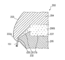
- FIG. 11 Shown in FIG. 11 is an enlarged cross-sectional view of a conventional annular spray nozzle 203 disclosed in the above-mentioned Patent Document 1.
- the spray nozzle 203 for generating the liquid jet 1S1 uses the gap 237 formed between the first member 204 and the second member 205 as a water flow passage 232.
- the flow path 232 includes an orifice 234 opened at the lower end, a reservoir 235 for temporarily storing the water 200S, and an introduction path 236 for introducing the water 200S from the reservoir 235 to the orifice 234.
- the water 200S travels obliquely downward in the introduction path 236 having a wedge-shaped longitudinal cross section, and a liquid jet directly from the orifice 234 toward the convergence point obliquely downward. It is injected as 1S1.
- the inventor of the present invention is that the configuration of such a conventional spray nozzle 203 is characterized in that the water 200S travels obliquely downward in the spray nozzle 203, and the circumferential disturbance or temporal change produced in the liquid jet is generated. It has been found that it is difficult to damp out such fluctuations, and it is difficult to spray water stably without interruption all around the circumference.
- Patent Document 2 Japanese Patent Application Laid-Open No. 62-151503
- Patent Document 2 Japanese Patent Application Laid-Open No. 62-151503
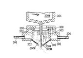
- It is an example of the manufacturing method of metal powder which prevents adhesion to metal wall surface 303 of metal powder by flowing fluid for adhesion prevention from fluid nozzle 308 along wall surface 303 above jet outlets. .
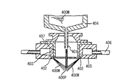
- FIG. 13 Another prior art shown in FIG. 13 is a spray nozzle 402 for spraying a high pressure fluid 400 W toward a falling flow of molten metal 400 M, as disclosed in JP-A 64-203 (Patent Document 3).
- the droplets of the molten metal adhere to the inner wall surface 407 by forming the inner wall surface 407 surrounding the falling flow with a material having a wettability of 90 ° to 180 ° with respect to the molten metal 400M. To prevent metal powder production.
- the surface of the inner wall surface 407 is rough and has fine unevenness, and a region where the contact angle is less than 90 ° locally occurs, and the molten metal 400M adheres and deposits on such a region, Over time, events often develop into blocking phenomena.
- Still another prior art shown in FIG. 14 is a coating layer made of a specific refractory material on the surface of the water jet nozzle 505 or its protection guide 506 disclosed in Japanese Patent Laid-Open No. 5-9513 (Patent Document 4).
- Patent Document 4 This is a method of preventing the adhesion blocking (blocking phenomenon) of the molten metal droplets by cooling the water jet nozzle 505 or its protection guide 506 by configuring the water nozzle 507.
- the covering layer 507 is made of a refractory material containing one or more of Si 3 N 4 , BN, or AlN, and having a porosity of 5% by volume or more. Molten metal does not adhere because 3 N 4 , BN or AlN decomposes. Further, by cooling the water jet nozzle 505 or its protection guide 506 from the inside by the cooling water 514, the coating layer 507 is kept at a low temperature, and the decomposition of the coating layer 507 due to the temperature rise is reduced.
- This technique is useful in preventing adhesion of molten metal to the water injection nozzle 505 and preventing blocking phenomenon.
- the coating layer 507 is locally decomposed due to the collision of droplets of molten metal, impurities derived from the coating layer 507 are mixed in the metal powder to be produced. That is, since the purity of the metal powder to be produced is low, there is a disadvantage that it can not be used as a raw material for high conductivity conductive paste in the field of electronics.
- the molten metal flows down from the melt nozzle in the form of a molten metal column.
- the inventor of the present invention is effective to keep the dynamic viscosity of the molten metal small in order to prevent clogging in the molten metal nozzle hole or to prevent the blocking phenomenon caused by the swing of the molten metal flowing down. I found it to be.
- FIG. 15 What is shown in FIG. 15 is a water atomizing method disclosed in Japanese Patent Application Laid-Open No. 8-143914 (Patent Document 5), in which the amount of S added to the molten metal is changed according to the water temperature of high pressure water to be sprayed. It is an apparatus.
- the apparatus includes a molten metal dropping means 601, a spray nozzle 603 for spraying high pressure water, a powder recovery chamber 605, a recovery pump 611, a cooling tank 609, a cooling tower 613, a recirculation pump 615, and a water temperature gauge 617. And a temperature display device 619.
- the temperature of the high pressure water sprayed rises with time and the viscosity decreases.
- the viscosity of the molten metal is lowered by reducing the amount of S added to the molten metal, and the balance with the decrease in viscosity accompanying the rise in the water temperature of the spray water is maintained. Powder can be produced.
- Patent Document 5 The idea of adjusting the viscosity of the molten metal disclosed in Patent Document 5 is also effective in preventing clogging of the molten metal nozzle hole and in preventing blocking phenomenon caused by the swing of the molten metal flowing down.
- the viscosity of the molten metal of metal is adjusted by adjusting the addition amount of S, it is inevitable that impurities are mixed in the metal powder to be manufactured. That is, there is a disadvantage that the purity of the metal powder to be produced is low and it can not be used as a raw material for high conductivity conductive paste etc. in the electronics field.
- JP 2007-291454 A Japanese Patent Application Laid-Open No. 62-151503 JP-A 64-203 JP-A-5-9513 JP-A-8-143914
- the metal powder manufacturing apparatus disclosed in Patent Document 1 has a path changing means for changing the path of the spray water after colliding with the molten metal column, and can obtain metal powder in which amorphization has progressed. It is not possible to obtain a crystallized metal powder suitable for a raw material such as a conductive paste of high conductivity in the field. Further, in the configuration of the conventional annular spray nozzle disclosed in Patent Document 1, it is difficult to attenuate circumferential disturbances or temporal fluctuations generated in the liquid jet, and the water is sprayed stably without interruption all around uniformly. It is difficult to do.
- the method for producing metal powder disclosed in Patent Document 2 intends to prevent adhesion of metal powder to the wall surface by flowing an adhesion preventing fluid along the wall surface on the upper side from the spray outlet of the spray nozzle. However, it is impossible to prevent seizure when the adhesion preventing fluid is blown away by air flow and the wall surface is exposed or when a large amount of molten metal touches and contacts the wall surface.
- the inner wall surface of the spray nozzle is made of a material having a wettability such that the contact angle with the molten metal is 90 ° to 180 °, so that the molten metal splashes.
- the method for preventing blocking phenomenon disclosed in Patent Document 4 comprises forming a coating layer made of a refractory material that decomposes when droplets of molten metal come in contact with the surface of a water jet nozzle or the like, and further cooling the water jet nozzle or the like.
- the purpose is to prevent the sticking and blocking (blocking phenomenon) of droplets of molten metal, but the conductive metal in the field of electronics has high conductivity because the metal powder produced is mixed with the impurities derived from the coating layer. It is not possible to obtain high purity metal powder suitable for raw materials such as organic pastes.
- the viscosity of the molten metal of metal is adjusted by adjusting the amount of addition of S according to the water temperature of the spray water to obtain a metal powder of stable quality.
- S is added to the molten metal, it is inevitable that impurities are mixed in the metal powder to be produced, and high purity suitable for raw materials such as high conductivity conductive pastes in the electronics field. There is a disadvantage that metal powder can not be obtained.
- the object of the present invention is to achieve high production efficiency and prevent clogging of molten metal nozzle holes and blocking phenomenon, so stable operation for a long time is possible, and high purity suitable for raw materials such as conductive paste of high conductivity in the electronics field. It is an object of the present invention to provide a silver powder production method and a silver powder production apparatus capable of obtaining silver powder of
- the present invention has been made to solve the above-mentioned problems, and in the first aspect of the present invention, molten silver is caused to flow down in a state of molten silver column, and the molten silver column is disposed so as to be a central axis.
- a method of producing a silver powder comprising at least a step of atomizing water onto the molten silver column from an annular spray nozzle to atomize the molten silver, the water being the top along a substantially inverted conical surface
- Melting the silver of the molten silver Column Tsu was micronized, and / or a silver powder manufacturing method characterized by further pulverizing into fine particles by the silver particles produced by atomization
- the water is allowed to travel from the outer edge side toward the inner edge side, with the gap sandwiched by the two annular surfaces curved upward toward the inner edge side as a flow path.
- the water is continuously sprayed along the substantially inverted conical surface by being applied downward to the annular reflecting surface, and the distance between the two annular surfaces defining the gap is on the inner edge side.
- the method of producing silver powder decreases toward the
- the diameter and the length of the suction pipe are set to be positioned.
- a hard carbon thin film is formed on the surface of the spray nozzle facing the molten silver column, the surface facing the molten silver flowing down, and the hard carbon thin film is a diamond thin film or DLC It is a film, and a water film is further formed by flowing water on the surface of the hard carbon thin film, thereby preventing silver from adhering to the hard carbon thin film and blocking phenomenon.
- the kinetic viscosity of the molten silver is 0.22 mm 2 / s or less by causing the molten silver to flow down from the melt nozzle and setting the temperature of the molten silver to 1400 ° C. or more and 1600 ° C. or less.
- the clogging of the melt nozzle and the blocking phenomenon are prevented, and the particle size of the produced silver powder is reduced.
- the diameter of the molten metal nozzle hole is 1 mm or more and 3 mm or less, and the average mass flow rate at which the molten silver flows down is 0.5 kg / min or more and 4.5 kg / min or less It is a silver powder manufacturing method in which the particle diameter of silver powder manufactured becomes small, so that the diameter of a nozzle hole is small.
- the material of the molten metal nozzle is any of aluminum nitride, silicon nitride, boron nitride, silicon carbide, magnesium oxide and aluminum oxide, preferably aluminum nitride or silicon nitride, and more preferably Is a method of producing silver powder which is silicon nitride.
- the eighth aspect of the present invention has a deionization step for producing deionized water from water, and produces silver powder to increase the purity of silver powder produced by spraying deionized water as the water. It is a method.
- a molten metal nozzle for causing molten silver to flow down in the form of molten silver columns, and water are sprayed along a substantially inverted conical surface so as to converge on a first convergent portion which is the top thereof.
- An apparatus for producing silver powder comprising: at least a spray nozzle for setting the position of the top portion inside the molten silver column; the spray nozzle having an axisymmetric suction pipe; As for the diameter and length of the water, the sprayed water atomizes the molten silver in the first convergence portion, the water having passed through the first convergence portion travels along a substantially conical surface, and the inner surface of the suction pipe
- the silver powder manufacturing apparatus is characterized in that it is set so as to strike and reflect on the first annular portion and to advance toward the second convergent portion which is the top thereof along the second substantially inverted conical surface.
- the spray nozzle comprises an upper annular member and a lower annular member facing each other at a distance, and the water is formed by using a gap between the two annular members as a flow passage.
- the upper surface of the lower annular member which advances from the outer edge side to the inner edge side and faces each other, and the lower surface of the upper annular member except for the innermost edge, both curve upward toward the inner edge at least at their inner edge.
- the eleventh aspect of the present invention 25 ° ⁇ ⁇ ⁇ 30 ° is satisfied, where ⁇ is the apex angle of the substantially inverted conical surface, and the second convergent portion is located above the lower end of the suction pipe. It is a silver powder manufacturing apparatus in which the diameter and the length of the suction pipe are set so as to be positioned.
- the twelfth aspect of the present invention is the surface of the spray nozzle facing the molten silver column, the surface facing the molten silver flowing down is coated with a hard carbon thin film, and the hard carbon thin film is a diamond thin film or DLC
- the film is a film, and the surface of the hard carbon thin film is coated with a water film by flowing water to prevent silver from adhering to the hard carbon thin film and blocking phenomenon.
- the thirteenth aspect of the present invention at least includes a heating means for heating silver to form molten silver, and a temperature control means for adjusting the temperature of the molten silver, wherein the temperature of the molten silver is 1400 ° C.
- a heating means for heating silver to form molten silver and a temperature control means for adjusting the temperature of the molten silver, wherein the temperature of the molten silver is 1400 ° C.
- the diameter of the molten metal nozzle hole is 1 mm or more and 3 mm or less, and the average mass flow rate at which the molten silver flows down is 0.5 kg / min or more and 4.5 kg / min or less It is a silver powder manufacturing device in which the particle diameter of silver powder manufactured becomes small, so that the diameter of a nozzle hole is small.
- the material of the molten metal nozzle is any of aluminum nitride, silicon nitride, boron nitride, silicon carbide, magnesium oxide and aluminum oxide, preferably aluminum nitride or silicon nitride, more preferably Is a silver powder manufacturing apparatus which is silicon nitride.
- the sixteenth embodiment of the present invention has a deionization apparatus for producing deionized water from water, and produces silver powder to increase the purity of silver powder produced by spraying deionized water as the water. It is an apparatus.
- the first aspect of the present invention it is possible to provide a silver powder production method capable of efficiently producing silver powder by micronizing molten silver at two places.
- the water is sprayed from the annular spray nozzle disposed so that the molten silver column is at the central axis so as to converge to the first convergent portion which is the top along the substantially inverted conical surface.
- the molten silver is micronized in the first convergence portion, and the water having passed through the first convergence portion travels along a substantially conical surface and is reflected on the first annular portion of the inner surface of the axisymmetric suction pipe,
- the molten silver of the molten silver column which proceeds along a second substantially inverted conical surface so as to converge to a second convergent portion which is the top thereof, and is not refined in the first convergent portion in the second convergent portion
- the water after the water is advanced from the outer edge side toward the inner edge side, with the gap sandwiched by the two annular surfaces curved upward toward the inner edge side as a flow path , And reflects downward toward the toroidal reflecting surface, and the distance between the two toroidal surfaces defining the gap decreases toward the inner edge side, so that the water may be all along the substantially inverted conical surface. It can spray without a break.
- the present inventors have found that water can be sprayed substantially uniformly without interruption around the entire circumference by adopting a configuration in which water is once applied to the annular reflecting surface and reflected downward. The reason is not clear, but the circumferential non-uniformity of the velocity of water as it rises diagonally upward against the gravity between the two annular surfaces whose distance decreases toward the inner edge side Components and time-varying components are attenuated, and when water strikes the toroidal reflecting surface, circumferential non-uniformity and temporal variation of the velocity of water are averaged and equalized, I think that I can spray almost uniformly all around the circumference.
- the molten silver since the size ⁇ of the apex angle of the substantially inverse conical surface is set to a small angle satisfying 25 ° ⁇ ⁇ ⁇ 30 °, the molten silver receives the impact of the spray water. Since a blocking phenomenon caused by blowing up is unlikely to occur, and the molten silver is pulverized at two points of the first convergent part and the second convergent part to make the molten silver into fine particles, a silver powder manufacturing method with high production efficiency Can be provided.
- the shape (diameter and length) of the suction pipe is set so that the second convergent portion is positioned above the lower end of the suction pipe, turbulence in the suctioned air flow is less likely to occur in the suction pipe. It is possible to suppress the occurrence of the blocking phenomenon caused by the swing of the spray water and the swing of the molten silver column.
- the shape (diameter and length) of the suction pipe is such that the water passing through the second convergent portion advances along the second substantially conical surface, and the second annular ring of the inner surface of the suction pipe Since the suction air flow is set so as not to occur in the suction pipe, it is possible to prevent the occurrence of the blocking phenomenon caused by the swing of the spray water and the swing of the molten silver column more reliably.
- a hard carbon thin film is formed on the surface facing the molten silver column of the spray nozzle and facing the molten silver flowing down, and the hard carbon thin film is a diamond thin film or a DLC film Further, since a water film is formed by flowing water on the surface of the hard carbon thin film, it is possible to provide a silver powder production method for preventing the adhesion of silver to the hard carbon thin film and the blocking phenomenon.
- the contact angle between the hard carbon thin film and the molten silver is in the range of 90 ° to 180 °, the hard carbon thin film has the property of not wetting to the molten silver.
- a hard carbon thin film can be formed on the surface of the spray nozzle by a method such as CVD, PVD, plating, or sputtering, and the surface can be formed microscopically flat, molten silver droplets are in contact However, adhesion and deposition are unlikely to occur.
- the dynamic viscosity of the molten silver is reduced to 0.22 mm 2 / s or less. It is possible to provide a silver powder manufacturing method which realizes smooth outflow of molten silver, prevents clogging of the molten metal nozzle holes and blocking phenomenon, and reduces the particle size of the manufactured silver powder.
- the temperature of the molten silver may be any temperature within the range of the melting point of silver (962 ° C.) to 1600 ° C., but the range of 1400 ° C. to 1600 ° C. is preferable for atomization without causing the blocking phenomenon. This is because if the temperature of molten silver is less than 1300 ° C., regardless of the material of the molten metal nozzle, the molten metal of silver does not flow out smoothly from the molten metal nozzle hole, so the above temperature is preferably 1300 ° C. or higher, Furthermore, in order to prevent clogging and blocking phenomenon of the molten metal nozzle hole, a temperature of 1400 ° C.
- the diameter of the molten metal nozzle hole is 1 mm or more and 3 mm or less
- the average mass flow rate at which the molten silver flows down is 0.5 kg / min or more and 4.5 kg / min or less
- the molten silver can be efficiently crushed at two places of the first convergent part and the second convergent part by spray water and silver powder can be manufactured, the apex angle of the substantially reverse conical surface to prevent the blocking phenomenon. If the diameter of the molten metal nozzle hole is set within the above range and the molten silver is made to flow down at a relatively large average mass flow of 0.5 kg / min or more and 4.5 kg / min or less, even if A large amount of silver powder can be produced. Moreover, the average particle diameter of the silver powder manufactured can be made small by selecting the diameter of a smaller molten metal nozzle hole within the said range.
- the material of the molten metal nozzle is any of aluminum nitride, silicon nitride, boron nitride, silicon carbide, magnesium oxide and aluminum oxide, preferably aluminum nitride or silicon nitride, and further, A method of producing silver powder, preferably silicon nitride, can be provided.
- the molten metal nozzle In order to prevent clogging of the molten silver in the molten metal nozzle hole, it is desirable to form the molten metal nozzle with a material having a large thermal conductivity. Therefore, aluminum nitride having the highest thermal conductivity is desired as the ceramic nozzle material. However, aluminum nitride has the disadvantage of brittle fracture during use due to the inherent thermal expansion of wurtzite crystals. Therefore, silicon nitride, which has high thermal conductivity and does not cause brittle fracture, is suitable as a nozzle material. In addition, silicon carbide, boron nitride, aluminum oxide, magnesium oxide or the like may be used as the material of the molten metal nozzle.
- a silver which has a deionization step for producing deionized water from water, and raises the purity of silver powder produced by spraying deionized water as the water. It is possible to provide a powder production method. According to the manufacturing method of the present embodiment, it is possible to manufacture a silver powder which has few impurities and is suitable for use in the field of electronics.
- high production is achieved by atomizing water from the spray nozzle onto the flowing down molten silver column and atomizing the molten silver at two points of the first convergence portion and the second convergence portion.
- An apparatus for producing silver powder capable of efficiently producing silver powder can be provided.
- the tenth aspect of the present invention after the water is advanced from the outer edge side toward the inner edge side, with the gap sandwiched by the two annular surfaces curved upward toward the inner edge side as a flow path The water is applied to the toroidal reflecting surface and reflected downward, and the distance between the two toroidal surfaces defining the gap is reduced toward the inner edge, thereby using the water It is possible to provide a silver powder production apparatus which sprays without interruption all around along the substantially inverted conical surface and suppresses the occurrence of blocking phenomenon due to the fluctuation of the molten silver column and the disturbance of the suction air flow.
- the size ⁇ of the apex angle of the substantially inverse conical surface is set to a small angle satisfying 25 ° ⁇ ⁇ ⁇ 30 °, a blocking phenomenon is less likely to occur, and molten silver Can be pulverized at two points of the first convergent part and the second convergent part to efficiently atomize the molten silver, so it is possible to provide a silver powder production apparatus with high production efficiency.
- the shape (diameter and length) of the suction pipe is set so that the second convergent portion is positioned above the lower end of the suction pipe, turbulence in the suctioned air flow is less likely to occur in the suction pipe. And the occurrence of blocking phenomenon can be suppressed.
- the shape (diameter and length) of the suction pipe is such that the water passing through the second converging portion travels along the second substantially conical surface and hits the second annular portion of the inner surface of the suction pipe Since the setting is made as described above, the disturbance of the suction air flow is less likely to occur in the suction pipe, and the occurrence of the blocking phenomenon can be prevented more reliably.
- a hard carbon thin film is formed on the surface facing the molten silver column of the spray nozzle and facing the flowing molten silver, and the hard carbon thin film is a diamond thin film or a DLC film Further, since a water film is formed by flowing water on the surface of the hard carbon thin film, it is possible to provide a silver powder production apparatus which prevents the adhesion of silver to the hard carbon thin film and the blocking phenomenon.
- the temperature of the molten silver by setting the temperature of the molten silver to 1400 ° C. or more and 1600 ° C. or less, the dynamic viscosity of the molten silver is reduced to 0.22 mm 2 / s or less, and clogging of the molten metal nozzle hole is caused. It is possible to provide a silver powder production apparatus which prevents the blocking phenomenon and reduces the particle size of the produced silver powder.
- the diameter of the molten metal nozzle hole is 1 mm or more and 3 mm or less
- the average mass flow rate at which the molten silver flows down is 0.5 kg / min or more and 4.5 kg / min or less
- a silver powder manufacturing apparatus which prevents clogging of a molten metal nozzle hole by using a material having high thermal conductivity and / or which is unlikely to cause brittle fracture as a molten metal nozzle. it can.
- deionized water as the water to be sprayed, it is possible to provide a silver powder production apparatus which produces silver powder suitable for use in the electronics field with few impurities.
- pure water or ultrapure water such as distilled water or RO water may be used instead of deionized water depending on the required purity of the silver powder and requirements of the production cost.
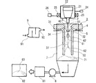
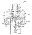
- FIG. 1 is an overall conceptual view showing one embodiment of a silver powder production apparatus of the present invention
- FIG. 2 is a cross-sectional view of a spray nozzle 3 in the present embodiment.
- a graphite crucible 21 is disposed in a tundish furnace 22 provided with heating means 2 ⁇ BR> T and a temperature control means 26, and silver in the graphite crucible 21 is heated by the heating means 25 to become molten silver 6, and the graphite crucible From the molten metal nozzle 2 attached to 21, it flows down in the state of molten silver column 61.
- the water having passed through the first converging portion 34 travels along the substantially conical surface 35, is reflected by the first annular portion 53 of the inner surface of the axisymmetric suction pipe 52, and converges to the second converging portion 37. Advance along a second generally inverse conical surface 36.
- the water micronizes the molten silver 6 which has not been micronized in the first converging section 34, and / or further micronizes the silver particles 62 micronized in the first converging section 34, Silver particles 62 are formed.
- the suction pipe 52 is sufficiently long, the water having passed through the second convergent portion 37 travels along the second substantially conical surface 38 and hits the second annular portion 54 of the inner surface of the axisymmetric suction pipe 52. .
- the generated silver particles 61 are deposited together with the water.
- the deposited silver particles 71 are transported to the filter means 81 together with the water by the suction and delivery action of the pump 8.
- the filter means 81 the water and the silver particles 61 are separated.
- the separated silver particles 61 are dried by a dryer 82 to obtain silver powder 83.
- the water sprayed from the spray nozzle 3 is deionized water to produce a silver powder of high purity.
- the silver powder production device 1 has a deionization device 9, which has an industrial water inlet 91 and a deionized water outlet 92. When water such as industrial water passes through the deionization device 9, it is deionized to be deionized water. Water such as industrial water is supplied to the deionized water inlet 91, and the deionized water flowing out from the deionized water outlet 92 is guided to the spray nozzle 3 as high-pressure water under pressure.
- the silver powder production storage 1 includes horizontal position adjusting means 24 for adjusting the horizontal position of the molten silver column 61. Since the first convergent portion 34 which is the top of the substantially inverted conical surface 33 can be set inside the molten silver column 6 by the horizontal position adjusting means 24, the molten silver 6 of the molten silver column 61 becomes the first convergent portion At 34, the silver particles 62 are efficiently crushed to form silver particles 62, and the axial symmetry of the traveling path of the water passing through the first converging portion 34 is ensured, and most of the water is along the substantially conical surface 35. After being advanced, the light can be reflected by the first annular portion 53, further advanced along the second substantially inverted conical surface 36, and collided with the molten silver column 61 again at the second convergent portion 37.
- the spray nozzle 3 has an annular slit (gap 31) through which water travels.
- the spray nozzle 3 has the upper annular member 4 and the lower annular member 5 opposed to each other with the gap 31 therebetween, and water is used as the flow channel in the direction of the arrow 32 indicating the advancing direction of water. It progresses toward the inner edge side from the outer edge side.
- the lower surface of the upper annular member 4 includes a curved upper annular surface 41
- the upper surface of the lower annular member 5 includes a curved lower annular surface 51, the upper annular surface 41 and the lower annular surface facing each other The interval of 51 is narrower toward the inner edge.
- the innermost edge of the lower surface of the upper annular member 4 is an annular reflecting surface 42 connected to the upper edge of the upper annular surface 41 without any step.
- the water which travels from the outer edge side to the inner edge side in the gap 31, is applied to the annular reflecting surface 42 and reflected downward, so that the water is a first converging portion along the substantially reverse conical surface 33. It is sprayed almost uniformly all around without interruption all around so that it converges to 34.
- the lower annular member 5 has an axisymmetric suction pipe 52 at its lower part, and the inner surface of the suction pipe 52 is smoothly connected to the inner surface of the lower annular member 5 excluding the suction pipe 52 without any step. Therefore, generation
- the shape of the inner surface of the suction tube 52 is not limited to a straight cylinder.
- the inner surface generally has the shape of a rotating surface obtained by rotating a smooth curve around an axis.
- the shape of the suction tube 52 is selected such that the first annular portion 53 to which the water passing through the first converging portion 34 is reflected is present on the inner surface of the suction tube 52.
- the molten silver 6 and / or the silver particles 62 can be made into fine particles again not only in the first converging portion 34 but also in the second converging portion 37, so a large amount of silver particles can be obtained in a short time. Can be generated efficiently.
- the inner diameter of the suction pipe 52 is D
- the length of the suction pipe 52 (more precisely, the suction pipe Assuming that the distance to the lower end of 52 is L, and the size of the apex angle of the substantially inverted conical surface 33 is ⁇ , the following equation 1 is established.
- the shape of the suction tube 52 is selected such that the second convergent portion 37 is located above the lowermost end of the suction tube 52.
- the shape of the suction tube 52 is selected such that the second annular portion 54 to which the water passed through the second converging portion 37 is reflected is present on the inner surface of the suction tube 52.
- the molten silver 6 can be efficiently micronized at two points, the first convergence portion and the second convergence portion.
- the diameter and the length of the suction pipe 52 satisfy the relationship L / D ⁇ 7. It is preferable to set as follows.
- the angle ⁇ formed by the water sprayed from the spray nozzle 3 that is, the apex angle ⁇ of the substantially inverted conical surface 33 to 30 ° or less, the suction force caused by the suction air flow caused by the sprayed water becomes strong, and the spray nozzle 3. It is possible to suppress adhesion and deposition of the silver particles 62 and the molten silver 6 to 3 and the particle size of the produced silver powder 83 is reduced.
- the angle ⁇ is usually in the range of 25 ° to 30 °.
- the preferable range of the angle ⁇ varies depending on the diameter of the spray nozzle 3, the spray pressure, the volumetric flow rate of water to be sprayed, and the like, and is not necessarily limited to the above range.
- FIG. 3 shows a hard carbon thin film 43 formed on the upper surface of the upper annular member 43 facing the molten silver column 61 in one embodiment of the present invention, and water is further flowed on the hard carbon thin film 43; It is sectional drawing of the spray nozzle 3 which formed the water film 44 by running water. The water sprayed from the spray nozzle 3 along the substantially inverted conical surface 33 atomizes the molten silver 6 of the molten silver column 61 in the first convergence portion 34 to generate silver particles 62.
- the hard carbon thin film 43 and the water film 44 by the flowing water prevent the droplets of the silver particles 62 and the molten silver 6 from adhering and depositing on the surface of the upper surface of the spray nozzle 3 facing the molten silver columns 61 to cause a blocking phenomenon. . Therefore, silver powder 83 can be manufactured stably in the present embodiment.
- the hard carbon thin film 43 is a diamond thin film or a DLC film, both of which are materials that do not react chemically with silver.
- the formation of the water film 44 by the flowing water is an operation performed to prevent adhesion and deposition of silver on the spray nozzle 3, but the formation of the hard carbon thin film 43 makes the effect more effective.
- the hard carbon thin film 43 is formed on the surface of the spray nozzle 3 using a method such as CVD, PVD, plating, or sputtering.
- the thickness of the hard carbon thin film 43 and the thickness of the water film 44 due to flowing water are not limited as long as the blocking phenomenon can be prevented.
- the thickness of the hard carbon thin film 43 preferable to prevent the blocking phenomenon and the thickness of the water film 44 by the preferable flowing water are the volumetric flow rate of water sprayed from the spray nozzle 3 and the average mass flow rate of the molten silver 6 flowing down. It depends on the apex angle ⁇ of the substantially inverted conical surface 33, the shape (diameter and length) of the suction pipe 52, and the like, and in particular, the volume flow rate of water sprayed from the spray nozzle 3.
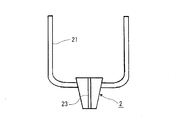
- FIG. 4 shows a graphite crucible 21 according to an embodiment of the present invention, a melt nozzle 2 attached thereto, and a melt nozzle hole 23 penetrating the melt nozzle 2.
- the molten silver 6 in the graphite crucible 21 flows through the molten metal nozzle hole 23 of the molten metal nozzle 2 in the state of the molten silver column 61.
- a high frequency induction heating furnace has been used as a tundish furnace 22 equipped with heating means 24, and a graphite crucible and a nozzle made of graphite have been used there.
- the thermal conductivity of graphite is very high at 80 W / (m ⁇ K) to 140 W / (m ⁇ K)
- graphite has the disadvantage of being brittle.
- the diameter of the molten metal nozzle hole 23 may be increased.
- the material of the molten metal nozzle 2 is any of aluminum nitride, silicon nitride, boron nitride, silicon carbide, magnesium oxide and aluminum oxide, more preferably aluminum nitride or silicon nitride, more preferably
- silicon nitride By using silicon nitride, it is possible to prevent the clogging of silver at the molten metal nozzle hole 23 and to manufacture a stable silver powder.
- Aluminum nitride and silicon nitride, which have high thermal conductivity, are suitable as the material of the melt nozzle 2, and among them, silicon nitride, in which brittle fracture does not occur, is particularly suitable as the material of the melt nozzle 2.
- the diameter of the molten metal nozzle hole 23 is in the range of 1 mm to 3 mm. The smaller the diameter is, the smaller the particle size of the produced silver powder 83 is.
- silver powder 83 of high purity can be produced.
- the water film 44 by the flowing water is deionized water from the viewpoint of increasing the purity of the silver powder 83. It is preferable to form by flowing.
- Example 1 40 kg of silver lumps were filled in a graphite crucible 21 in a high frequency melting furnace 22 and melted by raising the temperature to 1370 ° C. in a nitrogen atmosphere. After melting, water was sprayed using an annular spray nozzle 3 provided with a diamond thin film 43 and a water film 44 by flowing water while allowing the molten silver to flow down from the molten silicon nozzle 2 of silicon nitride.
- the spray pressure of water was 80 MPa, and the volumetric flow rate was 220 L / min.
- the said water and running water used deionized water.
- the diameter of the molten metal nozzle hole 23 was 1.8 mm, the average mass flow rate of the flowing down molten silver 6 was 2 kg / min, the suction pipe 52 was a straight cylindrical shape, the inner diameter D was 3 cm, and the length L was 25 cm.
- Silver is pulverized by spraying water from the spray nozzle 3 to form silver particles 62, and the silver particles 62 are generated and stored in the water tank 7, then filtered by the filter press 81 and dried at 60 ° C. in the dryer 82.
- FIG. 5 is a SEM image (JEOL JSM-6510) of silver powder 83 obtained in Example 1, and FIG. 6 similarly shows a particle size distribution (Nikkiso MT3300EXII). From the SEM image, the silver powder 83 contains particles in the shape of spheres, ovals, crushed particles, and the like. From the particle size distribution, the volume-based average particle diameter was 8.2 ⁇ m, and the number-based average particle diameter was 2.5 ⁇ m.
- FIG. 7 is a powder X-ray diffraction diagram (Shimazu XRD-6100) of the silver powder 83 obtained in Example 1.
- a CuK ⁇ ray was used as the X-ray source, and the applied voltage and applied current were 40 kV and 30 mA, respectively, and a range of 30 ° to 90 ° in 2 ⁇ was measured at a step width of 0.02 °.
- the crystallite size determined from the Debye-Scheller equation (Equation 4) was 18.4 nm.
- K is a form factor
- ⁇ is an X-ray wavelength
- ⁇ is a full width at half maximum
- ⁇ is a Bragg angle
- ⁇ is a size of a crystallite.
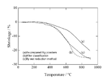
- FIG. 8 is a contraction curve of the silver paste using the silver powder 83 obtained in Example 1 as a raw material by thermomechanical analysis (RIGAK TMA 8310).
- Silver powder was prepared by mixing silver powder 83 with a vehicle in which ethyl cellulose was dissolved in butyl carbitol acetate.
- the mixing ratio of silver powder 83, ethyl cellulose and butyl carbitol acetate was 85 wt%: 2 wt%: 13 wt% by weight.
- the viscosity of the silver paste at this time was about 200 Pa ⁇ s.
- the silver paste was coated on a PET film with a doctor blade to a film thickness of about 250 ⁇ m and then dried at 100 ° C. for 2 hours.
- the film was peeled off from the PET film, cut into a 13 mm ⁇ disk shape, the sample was heated, and the temperature was raised to 900 ° C. at a temperature rising rate of 5 ° C./min.
- A) and (b) are the results according to the present invention, and the silver powder according to (b) uses a classifier to reduce the particle size of silver powder 83 of (a) to 2.5 ⁇ m or less, and (c) of It is almost the same as the particle size.
- (C) is the result of the silver powder manufactured by the wet reduction method.
- the contraction rate of (a) is smaller than that of (c) because the silver powder of (a) contains coarse particles.
- Table 1 shows the content of impurities contained in the silver powder 83 obtained in Example 1 in comparison with two comparative samples.
- the silver powder 83 was dissolved in dilute nitric acid, diluted to 100 ppm, and measured by an ICP emission spectrophotometer (Horiba ULTIMA 2).
- Comparative sample 1 is a silver powder produced by water atomization using private water (industrial water) as it is.
- Comparative sample 2 is a silver powder produced by a wet reduction method.
- the silver powder 83 of Example 1 contains less impurities than Comparative Sample 1 and Comparative Sample 2, and is suitable for use in the electronics field.
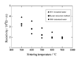
- FIG. 8 shows how the electrical resistivity after sintering of the silver paste using the silver powder 83 obtained in Example 1 as a raw material changes depending on the sintering temperature, in contrast to two comparative samples.
- Silver powder was prepared by mixing silver powder 83 with a vehicle in which ethyl cellulose was dissolved in butyl carbitol acetate.
- the mixing ratio of silver powder 83, ethyl cellulose and butyl carbitol acetate was 85 wt%: 2 wt%: 13 wt% by weight.
- the viscosity of the silver paste at this time was about 200 Pa ⁇ s.
- the silver paste was coated on a PET film with a doctor blade to a film thickness of about 250 ⁇ m and then dried at 100 ° C. for 2 hours.
- the film was peeled off from the PET film and cut into a 13 mm ⁇ disk to prepare five samples. Each sample was heated and heated up to 500 ° C., 600 ° C., 700 ° C., 800 ° C., or 900 ° C. at a heating rate of 5 ° C./min. After cooling to room temperature, a platinum electrode was attached to each sample and the specific resistance was measured with a multimeter (Mitsubishi Chemical MCP-T360).
- the circle marks show the results according to Example 1 of the present invention
- the triangle marks show the results of silver powder atomized with private water (industrial water)
- the square marks show the results of silver powder produced by the wet reduction method. Since the silver powder 83 of the present invention has a low impurity content, the sample after sintering exhibits the lowest electrical resistivity at any sintering temperature, and is suitable for use in the electronics field.
- Table 2 shows the presence or absence of occurrence of clogging of silver due to the material of the molten metal nozzle 2.
- Graphite, alumina and silicon nitride were used as the material of the molten metal nozzle 2.
- 25 kg of silver was dissolved at 1370 ° C., and water atomization was performed by spraying water having a pressure of 80 MPa and a volumetric flow rate of 220 L / min.
- the average mass flow rate of the flowing down molten silver 6 was 2 kg / min, and the diameter of the molten metal nozzle hole 23 was 1.8 mm.
- the impurities of the graphite crucible 21 are deposited on the nozzle during 25 kg of silver atomization to cause clogging of the molten metal nozzle hole 23.
- silicon nitride clogging does not occur even if 40 kg of silver is atomized.
- Silicon nitride is most excellent in toughness at high temperature and thermal shock resistance, and has a small thermal expansion coefficient. Therefore, the molten metal nozzle 2 made of silicon nitride is most reliable against temperature change during atomization.
- Table 3 shows how the presence or absence of the occurrence of the blocking phenomenon in the spray nozzle 3 changes depending on the angle (apex angle ⁇ ) of the water to be sprayed.
- Alumina was used for the molten metal nozzle 2. 25 kg of silver was melted at 1370 ° C., molten silver was made to flow at an average mass flow of 2 kg / min, and atomized by spraying water having a pressure of 80 MPa and a volumetric flow of 220 L / min.
- a straight cylindrical suction pipe 52 having an inner diameter D of 3 cm and a length L of 25 cm was used.
- the apex angle ⁇ By reducing the apex angle ⁇ , the droplets of molten silver are less likely to be scattered upward, and due to the suction force of the suction air flow, the adhesion of silver to the spray nozzle 3 is less likely to occur. In addition, when the apex angle ⁇ is reduced, the grinding of the molten silver is promoted, and the particle size of the produced silver powder becomes slightly smaller.
- Example 4 shows how the presence or absence of the occurrence of the blocking phenomenon in the spray nozzle 3 changes depending on the shape of the suction pipe 52 (ratio L / D of length).
- the melt nozzle 2 was made of alumina, and the diameter of the melt nozzle hole was 1.8 mm. 25 kg of silver was melted at 1370 ° C., molten silver was made to flow at an average mass flow of 2 kg / min, and atomized by spraying water having a pressure of 80 MPa and a volumetric flow of 220 L / min.
- the apex angle ⁇ was 25 °, and the inner diameter D of the straight cylindrical suction pipe 52 was 3 cm. As the length ratio L / D is larger, the disturbance of the suction air flow is reduced, so that the blocking phenomenon is less likely to occur.
- the silver powder produced by the water atomization method according to the present invention is high in purity and in progress of crystallization, and when used as a raw material of the conductive paste, exhibits high electric conductivity at a low sintering temperature. If used for electrode pastes, conductive pastes and inductors for solar cells, this will lead to improved reliability of energy saving devices and mobile devices. Moreover, since it is a manufacturing method with high production efficiency and capable of stable production for a long time, the production cost can be reduced.
- the silver powder production method and the new powder production apparatus of the present invention can be widely used in many industries related to the electronics field.
Landscapes
- Manufacture Of Metal Powder And Suspensions Thereof (AREA)
- Nozzles (AREA)
- Glanulating (AREA)
- Powder Metallurgy (AREA)
Abstract
[Problem] To provide a silver powder production method and silver powder production apparatus with which silver powder of high purity and high electric conductivity can be produced stably and at low cost. [Solution] Molten silver 6 flows down from a nozzle 2 for molten metal in the form of a molten silver rod 61. Water that is sprayed from a circular spray nozzle 3 toward a first convergence section 34 along a path approximating an inverted cone surface atomizes the molten silver 6 in the first convergence section 34 to form silver particles 62. The water that has passed through the first convergence section 34 advances along a path approximating a cone surface, is reflected at a first circular section 53 of the inner surface of an axially symmetric suction tube 52 and advances toward a second convergence section 37 along a second path approximating an inverted cone surface. At the second convergence section 37, the water atomizes the molten silver 6 that was not atomized in the first convergence section 34 to form more silver particles 62. The diameter and length of the suction tube 52 are set so that the second convergence section 37 is located above the lower end of the suction tube 52, and the angle θ of the path approximating an inverted cone surface is set to be 25° to 30°, preventing the occurrence of blocking.
Description
本願発明は、水アトマイズ、すなわち溶融銀柱の状態で流下させた溶融銀に水を噴霧することで銀粒子を生成する工程、を含む銀粉末製造方法と、当該製造方法を使用可能な銀粉末製造装置に関する。
The present invention comprises a method of producing silver powder comprising the steps of: water atomizing, that is, a step of forming silver particles by spraying water onto molten silver flowed down in the form of molten silver column, and a silver powder which can use the production method It relates to a manufacturing apparatus.
銀粉末は、装飾品の他に厚膜導電性ペースト、スルーホール用ペースト、導電性接着剤、インダクター、MLCC用電極、LTCC用電極、太陽電池用電極等のエレクトロニクス分野での原料として幅広く使用されている。上記エレクトロニクス分野で導電性ペースト等の原料として使用される銀粉末には、純度の高さ、結晶化、小さな平均粒径、粒径分布の一定の広がり、及び非球形の粒子形態の存在が求められる。高い電気伝導度と、導電性ペースト等の焼結時の低収縮性を確保するためである。
Silver powder is widely used as a raw material in electronics field such as thick film conductive paste, paste for through holes, conductive adhesive, inductor, electrode for MLCC, electrode for LTCC, electrode for solar cell etc. besides decorative products ing. The silver powder used as a raw material for the conductive paste etc. in the above-mentioned electronics field requires high purity, crystallization, small average particle diameter, uniform spread of particle diameter distribution, and presence of non-spherical particle form Be This is to ensure high electrical conductivity and low shrinkage during sintering of a conductive paste or the like.
このような用途に適した銀粉末の製造方法として現在、湿式還元法、粉砕法、噴霧熱分解法、アトマイズ法が知られている。
Currently, wet reduction methods, pulverization methods, spray pyrolysis methods and atomization methods are known as methods for producing silver powder suitable for such applications.
湿式還元法は、銀を硝酸等で溶解した後、沈殿剤と還元剤を添加して銀粉末を調製する方法であり、微細な粒径の銀粉末を製造することができる。しかし、溶媒中の分散性を維持するために界面活性剤を添加することから純粋な銀粉末を得ることができない欠点がある。また、固液分離、乾燥工程を含めて製造時間が非常に長く、大量の溶媒を使用するため環境負荷も大きい。
粉砕法は,銀の塊をボールミル等で粉砕する方法である。粉砕の際に大きな機械的エネルギーを要すること、及び長時間の粉砕処理を必要とする欠点がある。
噴霧熱分解法は、銀の原料塩を水溶液とし、超音波やノズルからの噴霧し、数百度に加熱した電気炉を通過させて銀粉末を製造する方法である。生産効率が低く、又、熱分解後の排ガス処理にコストがかかる点を考慮すると、現状では工業生産に適さない方法である。 The wet reduction method is a method in which silver is dissolved with nitric acid or the like and then a precipitant and a reducing agent are added to prepare silver powder, and silver powder with a fine particle diameter can be produced. However, there is a disadvantage that a pure silver powder can not be obtained from the addition of a surfactant to maintain the dispersibility in a solvent. In addition, the production time is very long including solid-liquid separation and drying steps, and the use of a large amount of solvent causes a large environmental load.
The grinding method is a method of grinding a silver lump with a ball mill or the like. The disadvantages are the high mechanical energy requirements for grinding and the need for prolonged grinding processes.
The spray pyrolysis method is a method in which a silver raw material salt is made into an aqueous solution, ultrasonic waves or a spray from a nozzle are made to pass through an electric furnace heated to several hundred degrees to produce silver powder. In view of the low production efficiency and the high cost of exhaust gas treatment after pyrolysis, this method is not suitable for industrial production at present.
アトマイズ法は、湿式還元法に比べて純粋な金属や合金を溶媒レスで短時間に製造でき、生産効率が高く、エネルギー損失も少ない方法である。
The atomization method is a method capable of producing a pure metal or alloy in a short time without solvent as compared with the wet reduction method, having high production efficiency and less energy loss.
アトマイズ法にはガスアトマイズ法と水アトマイズ法がある。ガスアトマイズ法で製造される金属粉末の粒径は10μm以上と大きく、一般にエレクトロニクス分野での使用には適さない。一方、水アトマイズ法で製造される金属粉末の粒径は微細であり、エレクトロニクス分野で使用することができる。
The atomizing method includes a gas atomizing method and a water atomizing method. The particle size of the metal powder produced by the gas atomization method is as large as 10 μm or more, and generally not suitable for use in the electronics field. On the other hand, the particle size of the metal powder produced by the water atomization method is fine and can be used in the electronics field.
従来の水アトマイズ法には、溶融金属を流下させる溶湯ノズル孔の目詰まりや、ブロッキング現象のために、しばしば製造が中断され、長時間の連続操業が難しいという欠点があった。
The conventional water atomizing method has a disadvantage that the production is often interrupted due to clogging of a molten metal nozzle hole which causes the molten metal to flow down and blocking phenomenon, and continuous operation for a long time is difficult.
ここでブロッキング現象について説明する。水アトマイズ法においては、溶融金属柱の状態で流下する溶融金属に噴霧ノズルから水を噴霧し、溶融金属を粉砕して金属微粒子を生成する。噴霧ノズルは通常、溶融金属柱を囲うように配置された環状のノズルである。ブロッキング現象とは、粉砕された後、本来下方へ進行するべき溶融金属の一部が半凝固状態で、噴霧された水の衝撃を受けて上方に向けて飛散し、噴霧ノズルに付着・堆積したり、生成した金属微粒子が上方に飛散し、噴霧ノズルに付着・堆積して、溶融金属の流下経路を妨げることを言う。
Here, the blocking phenomenon will be described. In the water atomization method, water is sprayed from a spray nozzle onto molten metal flowing down in the form of a molten metal column, and the molten metal is pulverized to form metal fine particles. The spray nozzle is usually an annular nozzle arranged to surround the molten metal column. In the blocking phenomenon, after being crushed, a part of the molten metal that should originally progress downward is in a semi-solidified state, splashed upward due to the impact of sprayed water, and adheres and deposits on the spray nozzle. Also, it is said that the generated metal fine particles fly upward, adhere to and deposit on the spray nozzle, and disturb the flow path of the molten metal.
ブロッキング現象の防止方法に係る従来技術はいくつか存在する。
1つの方法は、環状の噴霧ノズルから逆円錐状に噴霧される噴霧水の角度(逆円錐の頂角)を小さく設定し、斜め上方から鉛直に近い急な角度で溶融金属柱に向けて水を噴霧することで、溶融金属の一部が上方に向けて飛散しにくいようにする方法である。しかし当該方法には、上記頂角を小さく設定すると噴霧水が溶融金属柱に加える衝撃が小さくなり、金属粉末の製造効率が落ちるという欠点がある。 There are several prior art relating to methods for preventing blocking phenomena.
One method is to set the angle (apex angle of inverted cone) of the sprayed water sprayed in an inverted conical shape from the annular spray nozzle small, and direct the water toward the molten metal column from an oblique upper side at a steep angle close to the vertical Is a method of making it difficult for a portion of the molten metal to scatter upward. However, this method has the disadvantage that when the apex angle is set small, the impact of the spray water on the molten metal column is reduced and the production efficiency of the metal powder is reduced.
本願発明者は後述するように、噴霧された水の、溶融金属柱に衝突した後の進行方向を変更して再び溶融金属柱に衝突させることにより、上記頂角を小さく設定した場合に製造効率が低下するという上記欠点を回避できることを発見した。この発見は現時点で本願発明者が知る限り、先行技術文献には一切記載されていない。それを次に説明する。
図10に示すのは、特開2007-291454号公報(特許文献1)に開示された、溶融金属柱に衝突した後の噴霧水の進行方向を変化させる進行方向変更手段を有する金属粉末製造装置101である。当該装置101は、溶融金属1Qを供給する供給部102と、供給部102の下方に設けられた液体噴出部203と、液体噴出部203の下方に設けられたノズル106および筒状体109Aとを有している。ノズル106は、液体ジェット1S4(第2の液体)を噴射するオリフィス164を有しており、この液体ジェット1S4に、分散液1C1が衝突すると、分散液1C1の進行方向は強制的に変化する。すなわち、ノズル106は、分散液1C1の進行方向を変化させる進行方向変更手段を構成する。 The inventor of the present application changes the traveling direction of the sprayed water after it collides with the molten metal column, as described later, and makes the molten metal column collide again, thereby setting the above-mentioned apex angle small. It has been found that it is possible to avoid the above-mentioned drawbacks of This finding has not been described at all in the prior art as far as the present inventor knows at this time. It will be explained next.
What is shown in FIG. 10 is a metal powder manufacturing apparatus disclosed in Japanese Patent Application Laid-Open No. 2007-291454 (Patent Document 1) having a traveling direction changing means for changing the traveling direction of spray water after collision with a molten metal column. It is 101. Theapparatus 101 includes a supply unit 102 for supplying the molten metal 1Q, a liquid ejection unit 203 provided below the supply unit 102, and a nozzle 106 and a cylindrical body 109A provided below the liquid ejection unit 203. Have. The nozzle 106 has an orifice 164 for injecting a liquid jet 1S4 (second liquid), and when the dispersion liquid 1C1 collides with the liquid jet 1S4, the traveling direction of the dispersion liquid 1C1 is forcibly changed. That is, the nozzle 106 constitutes a traveling direction changing means for changing the traveling direction of the dispersion liquid 1C1.
図10に示すのは、特開2007-291454号公報(特許文献1)に開示された、溶融金属柱に衝突した後の噴霧水の進行方向を変化させる進行方向変更手段を有する金属粉末製造装置101である。当該装置101は、溶融金属1Qを供給する供給部102と、供給部102の下方に設けられた液体噴出部203と、液体噴出部203の下方に設けられたノズル106および筒状体109Aとを有している。ノズル106は、液体ジェット1S4(第2の液体)を噴射するオリフィス164を有しており、この液体ジェット1S4に、分散液1C1が衝突すると、分散液1C1の進行方向は強制的に変化する。すなわち、ノズル106は、分散液1C1の進行方向を変化させる進行方向変更手段を構成する。 The inventor of the present application changes the traveling direction of the sprayed water after it collides with the molten metal column, as described later, and makes the molten metal column collide again, thereby setting the above-mentioned apex angle small. It has been found that it is possible to avoid the above-mentioned drawbacks of This finding has not been described at all in the prior art as far as the present inventor knows at this time. It will be explained next.
What is shown in FIG. 10 is a metal powder manufacturing apparatus disclosed in Japanese Patent Application Laid-Open No. 2007-291454 (Patent Document 1) having a traveling direction changing means for changing the traveling direction of spray water after collision with a molten metal column. It is 101. The
特許文献1の金属粉末製造装置101において進行方向変更手段を設ける目的は、アモルファス化が進行した金属粉末を得るためである。進路変更手段がないと、溶融金属が分裂して生じた多数の液滴1Q1の周囲を覆うように形成された水蒸気層のために、液滴1Q1と液体ジェット1S1の間の熱伝導が妨げられて十分な冷却速度が得られず、結晶化の進行した金属粉末が得られる。進路変更手段を設けることで、半固化状態の液滴1Q1と水蒸気層とを、これらの慣性の大きさの違いを利用して分離し、冷却速度を確保し、アモルファス化が進行した金属粉末を得ることができる。しかし、進路変更手段として液体ジェット1S4(第2の液体)の噴射を用いる特許文献1の方法によっては、エレクトロニクス分野における高電導度の導電性ペースト等の原材料に適した、結晶化の進行した金属粉末を得ることはできない。又、特許文献1には、進路変更手段を用いることで、前記頂角が小さい場合にも金属粉末の製造効率が落ちないようにできる旨の記載は一切ない。
The purpose of providing the traveling direction changing means in the metal powder production apparatus 101 of Patent Document 1 is to obtain a metal powder in which the amorphization has progressed. Without the diverting means, the heat transfer between the droplet 1Q1 and the liquid jet 1S1 is impeded by the water vapor layer formed to cover the periphery of the multiple droplets 1Q1 generated by the molten metal split. A sufficient cooling rate can not be obtained, and a metal powder with advanced crystallization can be obtained. By providing a path change means, the semi-solidified droplet 1Q1 and the water vapor layer are separated using the difference in magnitude of these inertias, the cooling rate is secured, and the metal powder in which the amorphization has progressed You can get it. However, depending on the method of Patent Document 1 that uses the jet of liquid jet 1S4 (second liquid) as a course change means, a metal with advanced crystallization suitable as a raw material such as a conductive paste of high conductivity in the electronics field It is not possible to obtain a powder. Further, in Patent Document 1, there is no description at all by using the course change means that the production efficiency of the metal powder can be prevented from being lowered even when the apex angle is small.
ブロッキング現象は、逆円錐状に噴霧される水が溶融金属柱と衝突する収束点近傍で生じる何らかの外乱をきっかけとして、原因不明のまま突発的に生じることも多い。このような外乱の発生を減らすためには、環状の噴霧ノズルから、なるべく全周均一に途切れなく安定して水を噴霧することが望ましい。
The blocking phenomenon often occurs suddenly with unknown cause, triggered by any disturbance that occurs near the convergence point where the water sprayed in the reverse conical shape collides with the molten metal column. In order to reduce the occurrence of such disturbances, it is desirable to spray water from the annular spray nozzle as uniformly as possible around the entire circumference and stably.
図11に示すのは、上述の特許文献1に開示された、従来の環状の噴霧ノズル203の拡大断面図である。液体ジェット1S1を生成するための噴霧ノズル203は、第1の部材204と第2の部材205の間に形成された間隙237を水の流路232とする。流路232は、下端部に開口するオリフィス234と、水200Sを一時的に貯留する貯留部235と、貯留部235からオリフィス234に水200Sを導入する導入路236とにより構成される。
オリフィス234が下端部に開口しているため、水200Sは縦断面がくさび状をなす導入路236の中を斜め下方へと進行し、オリフィス234から直接、斜め下方の収束点へと向かう液体ジェット1S1として噴射される。本願発明者は、水200Sが噴霧ノズル203の中を斜め下方へと進行することを特徴とする、このような従来の噴霧ノズル203の構成では、液体ジェットに生じた周方向の乱れや時間的な変動が減衰しにくく、全周均一に途切れなく安定して水を噴霧することが困難であることを見出した。 Shown in FIG. 11 is an enlarged cross-sectional view of a conventionalannular spray nozzle 203 disclosed in the above-mentioned Patent Document 1. As shown in FIG. The spray nozzle 203 for generating the liquid jet 1S1 uses the gap 237 formed between the first member 204 and the second member 205 as a water flow passage 232. The flow path 232 includes an orifice 234 opened at the lower end, a reservoir 235 for temporarily storing the water 200S, and an introduction path 236 for introducing the water 200S from the reservoir 235 to the orifice 234.
Since theorifice 234 is open at the lower end, the water 200S travels obliquely downward in the introduction path 236 having a wedge-shaped longitudinal cross section, and a liquid jet directly from the orifice 234 toward the convergence point obliquely downward. It is injected as 1S1. The inventor of the present invention is that the configuration of such a conventional spray nozzle 203 is characterized in that the water 200S travels obliquely downward in the spray nozzle 203, and the circumferential disturbance or temporal change produced in the liquid jet is generated. It has been found that it is difficult to damp out such fluctuations, and it is difficult to spray water stably without interruption all around the circumference.
オリフィス234が下端部に開口しているため、水200Sは縦断面がくさび状をなす導入路236の中を斜め下方へと進行し、オリフィス234から直接、斜め下方の収束点へと向かう液体ジェット1S1として噴射される。本願発明者は、水200Sが噴霧ノズル203の中を斜め下方へと進行することを特徴とする、このような従来の噴霧ノズル203の構成では、液体ジェットに生じた周方向の乱れや時間的な変動が減衰しにくく、全周均一に途切れなく安定して水を噴霧することが困難であることを見出した。 Shown in FIG. 11 is an enlarged cross-sectional view of a conventional
Since the
ブロッキング現象の防止方法に係る他の従来技術として、溶融金属の一部が仮に上方に向かって飛散しても、噴霧ノズルに付着・堆積しにくくすることを意図した技術が複数ある。
As another prior art related to the method of preventing the blocking phenomenon, there are a plurality of techniques intended to make it difficult to adhere and deposit on the spray nozzle even if a part of the molten metal scatters upward.
そのような従来技術の1つとして図12に示すのは、特開昭62-151503号公報(特許文献2)に開示された、高圧流体300Wを溶融金属300Mに向けて噴射するための噴霧ノズル302の、噴射出口より上方側の壁面303に沿って、流体ノズル308から付着防止用流体を流すことにより金属粉末の壁面303への付着を防止する、金属粉末の製造方法の一実施例である。
One such prior art shown in FIG. 12 is a spray nozzle disclosed in Japanese Patent Application Laid-Open No. 62-151503 (Patent Document 2) for jetting high-pressure fluid 300 W toward molten metal 300 M. It is an example of the manufacturing method of metal powder which prevents adhesion to metal wall surface 303 of metal powder by flowing fluid for adhesion prevention from fluid nozzle 308 along wall surface 303 above jet outlets. .
この技術は、溶融金属300Mの飛沫が壁面303に向かって飛散しても、壁面303に衝突する前に付着防止用流体に接触して急冷凝固し、当該流体とともに下方へ押し流されることにより、壁面303に付着・堆積しないようにすることを意図したものである。しかし、この方法では、高圧流体300Wの噴流が引き起こす吸い込み気流により付着防止用流体が吹き飛ばされて壁面303の一部が露出した場合や、多量の溶融金属300Mが壁面303に触れて接触した場合の焼付を防止できない。
In this technique, even if droplets of the molten metal 300M are scattered toward the wall surface 303, they are brought into contact with the fluid for preventing adhesion before being collided with the wall surface 303, and are rapidly solidified together with the fluid to flow downward. It is intended not to adhere to or deposit on 303. However, in this method, the adhesion preventing fluid is blown away by the suction air flow caused by the jet of the high pressure fluid 300 W and a part of the wall surface 303 is exposed, or when a large amount of molten metal 300 M touches and contacts the wall surface 303. You can not prevent burn-in.
別の従来技術として図13に示すのは、特開昭64-203号公報(特許文献3)に開示された、高圧流体400Wを溶融金属400Mの落下流に向けて噴射するための噴霧ノズル402の、前記落下流を囲む内壁面407を、溶融金属400Mとの接触角が90°~180°の濡れ性を有する材質により構成することで、前記溶融金属の飛沫が内壁面407に付着することを防止する、金属粉末の製造方法である。
Another prior art shown in FIG. 13 is a spray nozzle 402 for spraying a high pressure fluid 400 W toward a falling flow of molten metal 400 M, as disclosed in JP-A 64-203 (Patent Document 3). The droplets of the molten metal adhere to the inner wall surface 407 by forming the inner wall surface 407 surrounding the falling flow with a material having a wettability of 90 ° to 180 ° with respect to the molten metal 400M. To prevent metal powder production.
この技術は、溶融金属400Mの飛沫が内壁面407に向かって飛散しても、内壁面407が溶融金属400Mで濡れない性質を有するために、当該飛沫の内壁面407への付着が防止され、内壁面407に付着・堆積しないようにすることを意図したものである。確かに理論上は、溶融金属400Mとの接触角が90°~180°の濡れ性を有する材質で内壁面407を構成すれば、付着は起こらない。しかし、現実には内壁面407の表面は粗くて微細な凹凸を有し、局所的に接触角が90°未満となる領域が生じて、そのような領域に溶融金属400Mが付着・堆積し、やがてはブロッキング現象へと発展する事象がしばしば起きる。
In this technique, even if the droplets of the molten metal 400M scatter toward the inner wall surface 407, the inner wall surface 407 does not get wet with the molten metal 400M, so adhesion of the droplets to the inner wall surface 407 is prevented. It is intended to prevent adhesion and deposition on the inner wall surface 407. Certainly, adhesion does not occur if the inner wall surface 407 is theoretically made of a material having a wettability of 90 ° to 180 ° with respect to the molten metal 400M. However, in reality, the surface of the inner wall surface 407 is rough and has fine unevenness, and a region where the contact angle is less than 90 ° locally occurs, and the molten metal 400M adheres and deposits on such a region, Over time, events often develop into blocking phenomena.
更に別の従来技術として図14に示すのは、特開平5-9513号公報(特許文献4)に開示された、水噴射ノズル505又はその保護ガイド506の表面に特定の耐火材料からなる被覆層507を構成し、更に水噴射ノズル505又はその保護ガイド506を冷却することで、溶融金属の飛沫の付着閉塞(ブロッキング現象)を防止する方法である。被覆層507は、Si3N4、BN又はAlNのうち1種又は2種以上を含み、気孔率が5容積%以上である耐火材料からなり、溶融金属の飛沫が接触すると700℃以上でSi3N4、BN又はAlNが分解するから、溶融金属が付着しない。又、冷却水514により水噴射ノズル505又はその保護ガイド506を内部から冷却することで、被覆層507を低温に保ち、昇温による被覆層507の分解を低減している。
Still another prior art shown in FIG. 14 is a coating layer made of a specific refractory material on the surface of the water jet nozzle 505 or its protection guide 506 disclosed in Japanese Patent Laid-Open No. 5-9513 (Patent Document 4). This is a method of preventing the adhesion blocking (blocking phenomenon) of the molten metal droplets by cooling the water jet nozzle 505 or its protection guide 506 by configuring the water nozzle 507. The covering layer 507 is made of a refractory material containing one or more of Si 3 N 4 , BN, or AlN, and having a porosity of 5% by volume or more. Molten metal does not adhere because 3 N 4 , BN or AlN decomposes. Further, by cooling the water jet nozzle 505 or its protection guide 506 from the inside by the cooling water 514, the coating layer 507 is kept at a low temperature, and the decomposition of the coating layer 507 due to the temperature rise is reduced.
この技術は、水噴射ノズル505への溶融金属の付着を防ぎブロッキング現象を防止する上では有用である。しかし、溶融金属の飛沫の衝突により被覆層507が局所的に分解するから、製造される金属粉末に被覆層507由来の不純物が混入する。すなわち、製造される金属粉末の純度が低いので、エレクトロニクス分野の高電導度の導電性ペースト等の原料として使用することができないという欠点がある。
This technique is useful in preventing adhesion of molten metal to the water injection nozzle 505 and preventing blocking phenomenon. However, since the coating layer 507 is locally decomposed due to the collision of droplets of molten metal, impurities derived from the coating layer 507 are mixed in the metal powder to be produced. That is, since the purity of the metal powder to be produced is low, there is a disadvantage that it can not be used as a raw material for high conductivity conductive paste in the field of electronics.
溶融金属は溶湯ノズルから溶融金属柱の状態で流下する。本願発明者は後述するように、溶湯ノズル孔における目詰まりを防止したり、流下する溶融金属の揺動に起因するブロッキング現象を防止するためには、溶融金属の動粘度を小さく保つことが有効であることを発見した。
The molten metal flows down from the melt nozzle in the form of a molten metal column. The inventor of the present invention, as described later, is effective to keep the dynamic viscosity of the molten metal small in order to prevent clogging in the molten metal nozzle hole or to prevent the blocking phenomenon caused by the swing of the molten metal flowing down. I found it to be.
図15に示すのは、特開平8-143914号公報(特許文献5)に開示された、噴霧する高圧水の水温に応じて金属の溶湯へのS添加量を変化させる水アトマイズ方法を使用する装置である。この装置は、溶湯落下手段601と、高圧水を噴霧する噴霧ノズル603と、粉末回収用チャンバ605と、回収ポンプ611と、冷却タンク609と、クーリングタワー613と、再循環ポンプ615と、水温計617と、温度表示装置619を備える。噴霧した高圧水を回収し、再循環させて再利用するので、時間経過に伴い、噴霧される高圧水の水温が上昇して粘性が低下する。それに合わせて、金属の溶湯へのS添加量を低下させることで溶湯の粘度を低下させ、噴霧水の水温上昇に伴う粘度低下とのバランスを保ち、水温の影響を受けることなく、ほぼ同じ様な粉末を製造することができる。
What is shown in FIG. 15 is a water atomizing method disclosed in Japanese Patent Application Laid-Open No. 8-143914 (Patent Document 5), in which the amount of S added to the molten metal is changed according to the water temperature of high pressure water to be sprayed. It is an apparatus. The apparatus includes a molten metal dropping means 601, a spray nozzle 603 for spraying high pressure water, a powder recovery chamber 605, a recovery pump 611, a cooling tank 609, a cooling tower 613, a recirculation pump 615, and a water temperature gauge 617. And a temperature display device 619. Since the sprayed high pressure water is recovered, recycled, and reused, the temperature of the high pressure water sprayed rises with time and the viscosity decreases. At the same time, the viscosity of the molten metal is lowered by reducing the amount of S added to the molten metal, and the balance with the decrease in viscosity accompanying the rise in the water temperature of the spray water is maintained. Powder can be produced.
特許文献5に開示された、金属の溶湯の粘度を調整するというアイデアは、溶湯ノズル孔の目詰まりの防止や、流下する溶融金属の揺動に起因するブロッキング現象の防止にも有効である。しかし、Sの添加量を調整することで金属の溶湯の粘度を調整するから、製造される金属粉末に不純物が混入することが避けられない。すなわち、製造される金属粉末の純度が低く、エレクトロニクス分野の高電導度の導電性ペースト等の原料として使用することができないという欠点がある。
The idea of adjusting the viscosity of the molten metal disclosed in Patent Document 5 is also effective in preventing clogging of the molten metal nozzle hole and in preventing blocking phenomenon caused by the swing of the molten metal flowing down. However, since the viscosity of the molten metal of metal is adjusted by adjusting the addition amount of S, it is inevitable that impurities are mixed in the metal powder to be manufactured. That is, there is a disadvantage that the purity of the metal powder to be produced is low and it can not be used as a raw material for high conductivity conductive paste etc. in the electronics field.
特許文献1に開示された金属粉末製造装置は、溶融金属柱に衝突した後の噴霧水の進路を変更する進路変更手段を有し、アモルファス化が進行した金属粉末を得ることができるが、エレクトロニクス分野における高電導度の導電性ペースト等の原材料に適した、結晶化の進行した金属粉末を得ることはできない。
又、特許文献1に開示された従来の環状の噴霧ノズルの構成では、液体ジェットに生じた周方向の乱れや時間的な変動が減衰しにくく、全周均一に途切れなく安定して水を噴霧することが困難である。
特許文献2に開示された金属粉末の製造方法は、噴霧ノズルの噴射出口から上方側の壁面に沿って付着防止用流体を流すことにより金属粉末の壁面への付着を防止することを意図しているが、気流で付着防止用流体が吹き飛ばされて壁面が露出した場合や、多量の溶融金属が壁面に触れて接触した場合の焼付を防止できない。
特許文献3に開示された金属粉末の製造方法は、噴霧ノズルの内壁面を、溶融金属との接触角が90°~180°の濡れ性を有する材質により構成することで、溶融金属の飛沫が内壁面に付着することを防止することを意図しているが、現実の内壁面は微細な凹凸を有し、局所的に接触角が90°未満となる領域が生じて、そのような領域に溶融金属400Mが付着・堆積し、やがてはブロッキング現象へと発展する事象がしばしば起きる欠点がある。
特許文献4に開示されたブロッキング現象の防止方法は、水噴射ノズル等の表面に、溶融金属の飛沫が接触すると分解する耐火材料からなる被覆層を構成し、更に水噴射ノズル等を冷却することで、溶融金属の飛沫の付着閉塞(ブロッキング現象)を防止することを意図しているが、製造される金属粉末に分解した被覆層由来の不純物が混入するため、エレクトロニクス分野の高電導度の導電性ペースト等の原料に適した高純度の金属粉末を得ることができない。
特許文献5に開示された合金鋼粉末の製造方法は、噴霧水の水温に応じてSの添加量を調整することで金属の溶湯の粘度を調整し、安定した品質の金属粉末を得ることを意図したものであるが、Sを溶湯に添加するから、製造される金属粉末に不純物が混入することが避けられず、エレクトロニクス分野の高電導度の導電性ペースト等の原料に適した高純度の金属粉末を得ることができないという欠点がある。 The metal powder manufacturing apparatus disclosed inPatent Document 1 has a path changing means for changing the path of the spray water after colliding with the molten metal column, and can obtain metal powder in which amorphization has progressed. It is not possible to obtain a crystallized metal powder suitable for a raw material such as a conductive paste of high conductivity in the field.
Further, in the configuration of the conventional annular spray nozzle disclosed inPatent Document 1, it is difficult to attenuate circumferential disturbances or temporal fluctuations generated in the liquid jet, and the water is sprayed stably without interruption all around uniformly. It is difficult to do.
The method for producing metal powder disclosed inPatent Document 2 intends to prevent adhesion of metal powder to the wall surface by flowing an adhesion preventing fluid along the wall surface on the upper side from the spray outlet of the spray nozzle. However, it is impossible to prevent seizure when the adhesion preventing fluid is blown away by air flow and the wall surface is exposed or when a large amount of molten metal touches and contacts the wall surface.
In the method for producing a metal powder disclosed inPatent Document 3, the inner wall surface of the spray nozzle is made of a material having a wettability such that the contact angle with the molten metal is 90 ° to 180 °, so that the molten metal splashes. Although it is intended to prevent adhesion to the inner wall surface, the actual inner wall surface has fine asperities, resulting in a region where the contact angle is locally less than 90 °, in such a region. There is a disadvantage that the molten metal 400M adheres and deposits, and events eventually develop into a blocking phenomenon.
The method for preventing blocking phenomenon disclosed inPatent Document 4 comprises forming a coating layer made of a refractory material that decomposes when droplets of molten metal come in contact with the surface of a water jet nozzle or the like, and further cooling the water jet nozzle or the like. The purpose is to prevent the sticking and blocking (blocking phenomenon) of droplets of molten metal, but the conductive metal in the field of electronics has high conductivity because the metal powder produced is mixed with the impurities derived from the coating layer. It is not possible to obtain high purity metal powder suitable for raw materials such as organic pastes.
According to the method of producing alloy steel powder disclosed inPatent Document 5, the viscosity of the molten metal of metal is adjusted by adjusting the amount of addition of S according to the water temperature of the spray water to obtain a metal powder of stable quality. Although intended, since S is added to the molten metal, it is inevitable that impurities are mixed in the metal powder to be produced, and high purity suitable for raw materials such as high conductivity conductive pastes in the electronics field. There is a disadvantage that metal powder can not be obtained.
又、特許文献1に開示された従来の環状の噴霧ノズルの構成では、液体ジェットに生じた周方向の乱れや時間的な変動が減衰しにくく、全周均一に途切れなく安定して水を噴霧することが困難である。
特許文献2に開示された金属粉末の製造方法は、噴霧ノズルの噴射出口から上方側の壁面に沿って付着防止用流体を流すことにより金属粉末の壁面への付着を防止することを意図しているが、気流で付着防止用流体が吹き飛ばされて壁面が露出した場合や、多量の溶融金属が壁面に触れて接触した場合の焼付を防止できない。
特許文献3に開示された金属粉末の製造方法は、噴霧ノズルの内壁面を、溶融金属との接触角が90°~180°の濡れ性を有する材質により構成することで、溶融金属の飛沫が内壁面に付着することを防止することを意図しているが、現実の内壁面は微細な凹凸を有し、局所的に接触角が90°未満となる領域が生じて、そのような領域に溶融金属400Mが付着・堆積し、やがてはブロッキング現象へと発展する事象がしばしば起きる欠点がある。
特許文献4に開示されたブロッキング現象の防止方法は、水噴射ノズル等の表面に、溶融金属の飛沫が接触すると分解する耐火材料からなる被覆層を構成し、更に水噴射ノズル等を冷却することで、溶融金属の飛沫の付着閉塞(ブロッキング現象)を防止することを意図しているが、製造される金属粉末に分解した被覆層由来の不純物が混入するため、エレクトロニクス分野の高電導度の導電性ペースト等の原料に適した高純度の金属粉末を得ることができない。
特許文献5に開示された合金鋼粉末の製造方法は、噴霧水の水温に応じてSの添加量を調整することで金属の溶湯の粘度を調整し、安定した品質の金属粉末を得ることを意図したものであるが、Sを溶湯に添加するから、製造される金属粉末に不純物が混入することが避けられず、エレクトロニクス分野の高電導度の導電性ペースト等の原料に適した高純度の金属粉末を得ることができないという欠点がある。 The metal powder manufacturing apparatus disclosed in
Further, in the configuration of the conventional annular spray nozzle disclosed in
The method for producing metal powder disclosed in
In the method for producing a metal powder disclosed in
The method for preventing blocking phenomenon disclosed in
According to the method of producing alloy steel powder disclosed in
本願発明の目的は、生産効率が高く、溶湯ノズル孔の目詰まりやブロッキング現象を起こさないので長時間の安定稼働ができ、エレクトロニクス分野の高電導度の導電性ペースト等の原料に適した高純度の銀粉末を得ることのできる銀粉末製造方法及び銀粉末製造装置を提供することである。
The object of the present invention is to achieve high production efficiency and prevent clogging of molten metal nozzle holes and blocking phenomenon, so stable operation for a long time is possible, and high purity suitable for raw materials such as conductive paste of high conductivity in the electronics field. It is an object of the present invention to provide a silver powder production method and a silver powder production apparatus capable of obtaining silver powder of
本願発明は上記課題を解決するためになされたものであり、本願発明の第1の形態は、溶融銀を溶融銀柱の状態で流下させ、前記溶融銀柱が中心軸となるように配置された環状の噴霧ノズルから水を前記溶融銀柱に噴霧して、前記溶融銀を微粒子化する工程を少なくとも有する銀粉末製造方法であり、前記水は略逆円錐面に沿ってその頂部である第1収束部に収束するように噴霧され、前記頂部の位置を前記溶融銀柱の内部に設定して、前記第1収束部において前記溶融銀を微粒子化し、前記第1収束部を経た前記水は略円錐面に沿って進行し、軸対称な吸引管の内面の第1円環部に当たって反射し、第2略逆円錐面に沿ってその頂部である第2収束部に収束するように進行し、前記第2収束部において、前記第1収束部で微粒子化されなかった前記溶融銀柱の溶融銀を微粒子化し、及び/又は、前記第1収束部で微粒子化により生成した銀粒子を更に粉砕して微粒子化することを特徴とする銀粉末製造方法である。
The present invention has been made to solve the above-mentioned problems, and in the first aspect of the present invention, molten silver is caused to flow down in a state of molten silver column, and the molten silver column is disposed so as to be a central axis. A method of producing a silver powder comprising at least a step of atomizing water onto the molten silver column from an annular spray nozzle to atomize the molten silver, the water being the top along a substantially inverted conical surface (1) Spraying so as to converge on a convergent portion, setting the position of the top to the inside of the molten silver column, atomizing the molten silver in the first convergent portion, the water passing through the first convergent portion is It travels along a generally conical surface and strikes the first annulus of the inner surface of the axisymmetric aspiration tube, reflects it, and travels along a second generally inverted conical surface to converge on its second convergent portion And in the second convergent portion, the first convergent portion is not pulverized. Melting the silver of the molten silver Column Tsu was micronized, and / or a silver powder manufacturing method characterized by further pulverizing into fine particles by the silver particles produced by atomization by the first converging portion.
本願発明の第2の形態は、前記水を、いずれも内縁側ほど上方に湾曲した2つの円環面で挟まれた間隙を流路として、外縁側から内縁側に向けて進行させた後、円環状反射面に当てて下方に向けて反射することで、前記水が前記略逆円錐面に沿って全周途切れなく噴霧され、前記間隙を画成する2つの円環面の間隔は内縁側に向かって減少する銀粉末製造方法である。
According to a second aspect of the present invention, the water is allowed to travel from the outer edge side toward the inner edge side, with the gap sandwiched by the two annular surfaces curved upward toward the inner edge side as a flow path. The water is continuously sprayed along the substantially inverted conical surface by being applied downward to the annular reflecting surface, and the distance between the two annular surfaces defining the gap is on the inner edge side. The method of producing silver powder decreases toward the
本願発明の第3の形態は、前記略逆円錐面の頂角の大きさをθとしたとき25°≦θ≦30°が成立し、前記第2収束部が前記吸引管の下端より上方に位置するように、前記吸引管の径及び長さが設定される銀粉末製造方法である。
In the third aspect of the present invention, 25 ° ≦ θ ≦ 30 ° is satisfied, where θ is the apex angle of the substantially inverted conical surface, and the second convergent portion is located above the lower end of the suction pipe. In the silver powder manufacturing method, the diameter and the length of the suction pipe are set to be positioned.
本願発明の第4の形態は、前記噴霧ノズルの前記溶融銀柱に対向する表面であって、流下する前記溶融銀に向かい合う表面に硬質炭素薄膜を形成し、前記硬質炭素薄膜はダイヤモンド薄膜又はDLC膜であり、更に前記硬質炭素薄膜の表面に水を流すことにより水膜を形成して、前記硬質炭素薄膜への銀の付着とブロッキング現象を防止する銀粉末製造方法である。
According to a fourth aspect of the present invention, a hard carbon thin film is formed on the surface of the spray nozzle facing the molten silver column, the surface facing the molten silver flowing down, and the hard carbon thin film is a diamond thin film or DLC It is a film, and a water film is further formed by flowing water on the surface of the hard carbon thin film, thereby preventing silver from adhering to the hard carbon thin film and blocking phenomenon.
本願発明の第5の形態は、前記溶融銀が溶湯ノズルから流下し、前記溶融銀の温度を1400℃以上1600℃以下とすることで、前記溶融銀の動粘度を0.22mm2/s以下に低下させて前記溶湯ノズルの目詰まりとブロッキング現象を防止し、製造される銀粉末の粒径を小さくする銀粉末製造方法である。
According to a fifth aspect of the present invention, the kinetic viscosity of the molten silver is 0.22 mm 2 / s or less by causing the molten silver to flow down from the melt nozzle and setting the temperature of the molten silver to 1400 ° C. or more and 1600 ° C. or less. In the method of producing a silver powder, the clogging of the melt nozzle and the blocking phenomenon are prevented, and the particle size of the produced silver powder is reduced.
本願発明の第6の形態は、前記溶湯ノズル孔の直径が1mm以上3mm以下であり、前記溶融銀が流下する平均質量流量が0.5kg/min以上4.5kg/min以下であり、前記溶湯ノズル孔の直径が小さいほど製造される銀粉末の粒径が小さくなる銀粉末製造方法である。
In a sixth aspect of the present invention, the diameter of the molten metal nozzle hole is 1 mm or more and 3 mm or less, and the average mass flow rate at which the molten silver flows down is 0.5 kg / min or more and 4.5 kg / min or less It is a silver powder manufacturing method in which the particle diameter of silver powder manufactured becomes small, so that the diameter of a nozzle hole is small.
本願発明の第7の形態は、前記溶湯ノズルの材質が窒化アルミニウム、窒化ケイ素、窒化ホウ素、炭化ケイ素、酸化マグネシウム、酸化アルミニウムのいずれかであり、好ましくは窒化アルミニウム又は窒化ケイ素であり、更に好ましくは窒化ケイ素である銀粉末製造方法である。
In the seventh aspect of the present invention, the material of the molten metal nozzle is any of aluminum nitride, silicon nitride, boron nitride, silicon carbide, magnesium oxide and aluminum oxide, preferably aluminum nitride or silicon nitride, and more preferably Is a method of producing silver powder which is silicon nitride.
本願発明の第8の形態は、水から脱イオン水を製造するための脱イオン工程を有し、前記水として脱イオン水を噴霧することで製造される銀粉末の純度を高くする銀粉末製造方法である。
The eighth aspect of the present invention has a deionization step for producing deionized water from water, and produces silver powder to increase the purity of silver powder produced by spraying deionized water as the water. It is a method.
本願発明の第9の形態は、溶融銀を溶融銀柱の状態で流下させるための溶湯ノズルと、水を略逆円錐面に沿ってその頂部である第1収束部に収束するように噴霧するための噴霧ノズルと、前記頂部の位置を前記溶融銀柱の内部に設定する水平位置調整手段を少なくとも有する銀粉末製造装置であり、前記噴霧ノズルは軸対称な吸引管を有し、前記吸引管の径及び長さは、噴霧された前記水が前記第1収束部において前記溶融銀を微粒子化し、前記第1収束部を経た前記水が略円錐面に沿って進行し、前記吸引管の内面の第1円環部に当たって反射し、第2略逆円錐面に沿ってその頂部である第2収束部に向かって進行するように設定されることを特徴とする銀粉末製造装置である。
In a ninth aspect of the present invention, a molten metal nozzle for causing molten silver to flow down in the form of molten silver columns, and water are sprayed along a substantially inverted conical surface so as to converge on a first convergent portion which is the top thereof. An apparatus for producing silver powder, the apparatus comprising: at least a spray nozzle for setting the position of the top portion inside the molten silver column; the spray nozzle having an axisymmetric suction pipe; As for the diameter and length of the water, the sprayed water atomizes the molten silver in the first convergence portion, the water having passed through the first convergence portion travels along a substantially conical surface, and the inner surface of the suction pipe The silver powder manufacturing apparatus is characterized in that it is set so as to strike and reflect on the first annular portion and to advance toward the second convergent portion which is the top thereof along the second substantially inverted conical surface.
本願発明の第10の形態は、前記噴霧ノズルは、離間して対面する上側環状部材と下側環状部材からなり、前記水は、両環状部材で挟まれた間隙を流路として両環状部材の外縁側から内縁側へ向かって進行し、互いに対面する前記下側環状部材の上面と、最内縁部を除く前記上側環状部材の下面はいずれも、少なくともそれらの内縁部において内縁側ほど上方に湾曲した円環面の形状を有し、前記間隙を画成する2つの前記円環面の間隔は内縁側に向かって減少し、前記上側環状部材の下面の前記最内縁部は、前記上側環状部材に係る前記円環面の上縁部と段差なく接続する円環状反射面であり、前記流路を進行した前記水を、前記円環状反射面に当てて下方に向けて反射することで、前記水が前記略逆円錐面に沿って前記第1収束部に収束するように全周途切れなく噴霧される銀粉末製造装置である。
According to a tenth aspect of the present invention, the spray nozzle comprises an upper annular member and a lower annular member facing each other at a distance, and the water is formed by using a gap between the two annular members as a flow passage. The upper surface of the lower annular member, which advances from the outer edge side to the inner edge side and faces each other, and the lower surface of the upper annular member except for the innermost edge, both curve upward toward the inner edge at least at their inner edge. And the distance between the two annular surfaces defining the gap decreases toward the inner edge, and the innermost edge of the lower surface of the upper annular member is the upper annular member The annular reflecting surface connected to the upper edge portion of the annular surface according to the present invention without any level difference, and the water having traveled through the flow path is applied to the annular reflecting surface and reflected downward; Water is collected in the first converging portion along the substantially inverted conical surface. Silver powder production apparatus to be sprayed seamlessly entire circumference to.
本願発明の第11の形態は、前記略逆円錐面の頂角の大きさをθとしたとき25°≦θ≦30°が成立し、前記第2収束部が前記吸引管の下端より上方に位置するように、前記吸引管の径及び長さが設定される銀粉末製造装置である。
In the eleventh aspect of the present invention, 25 ° ≦ θ ≦ 30 ° is satisfied, where θ is the apex angle of the substantially inverted conical surface, and the second convergent portion is located above the lower end of the suction pipe. It is a silver powder manufacturing apparatus in which the diameter and the length of the suction pipe are set so as to be positioned.
本願発明の第12の形態は、前記噴霧ノズルの前記溶融銀柱に対向する表面であって、流下する前記溶融銀に向かい合う表面は硬質炭素薄膜で被覆され、前記硬質炭素薄膜はダイヤモンド薄膜又はDLC膜であり、更に前記硬質炭素薄膜の表面は流水による水膜で被覆され、前記硬質炭素薄膜への銀の付着とブロッキング現象を防止する銀粉末製造装置である。
The twelfth aspect of the present invention is the surface of the spray nozzle facing the molten silver column, the surface facing the molten silver flowing down is coated with a hard carbon thin film, and the hard carbon thin film is a diamond thin film or DLC The film is a film, and the surface of the hard carbon thin film is coated with a water film by flowing water to prevent silver from adhering to the hard carbon thin film and blocking phenomenon.
本願発明の第13の形態は、銀を加熱して溶融銀とするための加熱手段と、前記溶融銀の温度を調節するための温度制御手段を少なくとも有し、前記溶融銀の温度を1400℃以上1600℃以下とすることで、前記溶融銀の動粘度を0.22mm2/s以下に低下させて前記溶湯ノズルの目詰まりとブロッキング現象を防止し、製造される銀粉末の粒径を小さくする銀粉末製造装置である。
The thirteenth aspect of the present invention at least includes a heating means for heating silver to form molten silver, and a temperature control means for adjusting the temperature of the molten silver, wherein the temperature of the molten silver is 1400 ° C. By setting the temperature to 1600 ° C. or lower, the dynamic viscosity of the molten silver is reduced to 0.22 mm 2 / s or less to prevent clogging of the molten metal nozzle and blocking phenomenon, and the particle diameter of the produced silver powder is reduced. Silver powder production equipment.
本願発明の第14の形態は、前記溶湯ノズル孔の直径が1mm以上3mm以下であり、前記溶融銀が流下する平均質量流量が0.5kg/min以上4.5kg/min以下であり、前記溶湯ノズル孔の直径が小さいほど製造される銀粉末の粒径が小さくなる銀粉末製造装置である。
In a fourteenth aspect of the present invention, the diameter of the molten metal nozzle hole is 1 mm or more and 3 mm or less, and the average mass flow rate at which the molten silver flows down is 0.5 kg / min or more and 4.5 kg / min or less It is a silver powder manufacturing device in which the particle diameter of silver powder manufactured becomes small, so that the diameter of a nozzle hole is small.
本願発明の第15の形態は、前記溶湯ノズルの材質が窒化アルミニウム、窒化ケイ素、窒化ホウ素、炭化ケイ素、酸化マグネシウム、酸化アルミニウムのいずれかであり、好ましくは窒化アルミニウム又は窒化ケイ素であり、更に好ましくは窒化ケイ素である銀粉末製造装置である。
In the fifteenth mode of the present invention, the material of the molten metal nozzle is any of aluminum nitride, silicon nitride, boron nitride, silicon carbide, magnesium oxide and aluminum oxide, preferably aluminum nitride or silicon nitride, more preferably Is a silver powder manufacturing apparatus which is silicon nitride.
本願発明の第16の形態は、水から脱イオン水を製造するための脱イオン装置を有し、前記水として脱イオン水を噴霧することで製造される銀粉末の純度を高くする銀粉末製造装置である。
The sixteenth embodiment of the present invention has a deionization apparatus for producing deionized water from water, and produces silver powder to increase the purity of silver powder produced by spraying deionized water as the water. It is an apparatus.
本願発明の第1の形態によれば、溶融銀を2箇所で微粒子化することにより、効率良く銀粉末を製造することができる銀粉末製造方法を提供できる。
According to the first aspect of the present invention, it is possible to provide a silver powder production method capable of efficiently producing silver powder by micronizing molten silver at two places.
すなわち本形態によれば、溶融銀柱が中心軸となるように配置された環状の噴霧ノズルから、水が略逆円錐面に沿ってその頂部である第1収束部に収束するように噴霧され、前記第1収束部において前記溶融銀を微粒子化し、前記第1収束部を経た前記水は略円錐面に沿って進行し、軸対称な吸引管の内面の第1円環部に当たって反射し、第2略逆円錐面に沿ってその頂部である第2収束部に収束するように進行し、前記第2収束部において、前記第1収束部で微粒子化されなかった前記溶融銀柱の溶融銀を微粒子化し、及び/又は、前記第1収束部で微粒子化により生成した銀粒子を更に粉砕して微粒子化するから、ブロッキング現象防止のために前記略逆円錐面の頂角を小さく設定したとしても、高い生産効率で銀粉末を製造することができる。
That is, according to the present embodiment, the water is sprayed from the annular spray nozzle disposed so that the molten silver column is at the central axis so as to converge to the first convergent portion which is the top along the substantially inverted conical surface. The molten silver is micronized in the first convergence portion, and the water having passed through the first convergence portion travels along a substantially conical surface and is reflected on the first annular portion of the inner surface of the axisymmetric suction pipe, The molten silver of the molten silver column, which proceeds along a second substantially inverted conical surface so as to converge to a second convergent portion which is the top thereof, and is not refined in the first convergent portion in the second convergent portion And / or further pulverize the silver particles produced by atomization in the first convergent portion by pulverizing the silver particles, so that the apex angle of the substantially inverted conical surface is set small to prevent the blocking phenomenon. Also, to produce silver powder with high production efficiency It can be.
本願発明の第2の形態によれば、水を、いずれも内縁側ほど上方に湾曲した2つの円環面で挟まれた間隙を流路として、外縁側から内縁側に向けて進行させた後、円環状反射面に当てて下方に向けて反射し、前記間隙を画成する2つの円環面の間隔は内縁側に向かって減少するから、前記水を前記略逆円錐面に沿って全周途切れなく噴霧することができる。水が全周途切れなく噴霧され、周方向にほぼ一様に噴霧されるから、噴霧水が溶融銀柱に及ぼす力積のベクトル和がほぼゼロとなり、溶融銀柱の揺動や吸い込み気流の乱れに起因するブロッキング現象の発生を抑制することができる銀粉末製造方法を提供できる。
According to the second aspect of the present invention, after the water is advanced from the outer edge side toward the inner edge side, with the gap sandwiched by the two annular surfaces curved upward toward the inner edge side as a flow path , And reflects downward toward the toroidal reflecting surface, and the distance between the two toroidal surfaces defining the gap decreases toward the inner edge side, so that the water may be all along the substantially inverted conical surface. It can spray without a break. Since water is sprayed without interruption all around the circumference and sprayed almost uniformly in the circumferential direction, the vector sum of the impulse that the spray water exerts on the molten silver column becomes almost zero, and the fluctuation of the molten silver column and the disturbance of the suction air flow It is possible to provide a silver powder manufacturing method capable of suppressing the occurrence of blocking phenomenon caused by
本願発明者等は、水を一度、円環状反射面に当てて下方に向けて反射する構成を採用することで、水を全周途切れなくほぼ均一に噴霧可能であることを見出した。その理由は定かではないが、水が内縁側に向かってその間隔が減少する2つの円環面の間を重力に逆らって斜め上向きに上昇する際に、水の速度の周方向の非一様成分や時間変動成分が減衰すること、及び、水が円環状反射面に当たって反射する際に、水の速度の周方向の非一様性や時間的な変動が平均化・均一化されて、水を全周途切れなくほぼ均一に噴霧することができるものと思量する。
The present inventors have found that water can be sprayed substantially uniformly without interruption around the entire circumference by adopting a configuration in which water is once applied to the annular reflecting surface and reflected downward. The reason is not clear, but the circumferential non-uniformity of the velocity of water as it rises diagonally upward against the gravity between the two annular surfaces whose distance decreases toward the inner edge side Components and time-varying components are attenuated, and when water strikes the toroidal reflecting surface, circumferential non-uniformity and temporal variation of the velocity of water are averaged and equalized, I think that I can spray almost uniformly all around the circumference.
本願発明の第3の形態によれば、前記略逆円錐面の頂角の大きさθを25°≦θ≦30°を満たす小さな角に設定するから、噴霧水の衝撃を受けて溶融銀が吹き上げることに起因するブロッキング現象が発生しにくく、かつ、溶融銀を第1収束部と第2収束部の2箇所で粉砕して溶融銀を微粒子化するから、生産効率の高い銀粉末製造方法を提供できる。本形態においては、吸引管の形状(径及び長さ)が、前記第2収束部が前記吸引管の下端より上方に位置するように設定されるから、吸引管内で吸い込み気流の乱れが生じにくく、噴霧水の揺動や溶融銀柱の揺動に起因するブロッキング現象の発生を抑制することができる。
According to the third aspect of the present invention, since the size θ of the apex angle of the substantially inverse conical surface is set to a small angle satisfying 25 ° ≦ θ ≦ 30 °, the molten silver receives the impact of the spray water. Since a blocking phenomenon caused by blowing up is unlikely to occur, and the molten silver is pulverized at two points of the first convergent part and the second convergent part to make the molten silver into fine particles, a silver powder manufacturing method with high production efficiency Can be provided. In this embodiment, since the shape (diameter and length) of the suction pipe is set so that the second convergent portion is positioned above the lower end of the suction pipe, turbulence in the suctioned air flow is less likely to occur in the suction pipe. It is possible to suppress the occurrence of the blocking phenomenon caused by the swing of the spray water and the swing of the molten silver column.
更に、本形態の変形例においては、吸引管の形状(径及び長さ)が、第2収束部を経た水が第2略円錐面に沿って進行し、吸引管の内面の第2円環部に当たるように設定されるから、吸引管内で吸い込み気流の乱れが生じにくく、噴霧水の揺動や溶融銀柱の揺動に起因するブロッキング現象の発生をより確実に防止することができる。
Furthermore, in the modification of the present embodiment, the shape (diameter and length) of the suction pipe is such that the water passing through the second convergent portion advances along the second substantially conical surface, and the second annular ring of the inner surface of the suction pipe Since the suction air flow is set so as not to occur in the suction pipe, it is possible to prevent the occurrence of the blocking phenomenon caused by the swing of the spray water and the swing of the molten silver column more reliably.
本願発明の第4の形態によれば、噴霧ノズルの溶融銀柱に対向する表面であって、流下する溶融銀に向かい合う表面に硬質炭素薄膜を形成し、前記硬質炭素薄膜はダイヤモンド薄膜又はDLC膜であり、更に前記硬質炭素薄膜の表面に水を流すことにより水膜を形成するから、前記硬質炭素薄膜への銀の付着とブロッキング現象を防止する銀粉末製造方法を提供できる。
According to the fourth aspect of the present invention, a hard carbon thin film is formed on the surface facing the molten silver column of the spray nozzle and facing the molten silver flowing down, and the hard carbon thin film is a diamond thin film or a DLC film Further, since a water film is formed by flowing water on the surface of the hard carbon thin film, it is possible to provide a silver powder production method for preventing the adhesion of silver to the hard carbon thin film and the blocking phenomenon.
硬質炭素薄膜と溶融銀の接触角は90°~180°の範囲にあるため、硬質炭素薄膜は溶融銀に対して濡れない性質を有する。又、噴霧ノズルの表面にCVD、PVD、メッキ、スパッタリング等の方法で硬質炭素薄膜を形成し、その表面を微視的にも平坦に形成することが可能であるから、溶融銀の飛沫が接触しても付着・堆積は起こりにくい。しかし、多量の溶融銀の飛沫が接触して焼付を起こすと硬質炭素薄膜が昇温により脆弱となって剥離し、剥離部分から溶融銀の付着・堆積が進行してブロッキング現象を引き起こすおそれがある。そこで、接触する溶融銀の飛沫を洗い流し、かつ硬質炭素薄膜を冷却する目的で、その表面に水膜を形成するものである。
Since the contact angle between the hard carbon thin film and the molten silver is in the range of 90 ° to 180 °, the hard carbon thin film has the property of not wetting to the molten silver. In addition, since a hard carbon thin film can be formed on the surface of the spray nozzle by a method such as CVD, PVD, plating, or sputtering, and the surface can be formed microscopically flat, molten silver droplets are in contact However, adhesion and deposition are unlikely to occur. However, when a large amount of molten silver droplets come in contact and cause seizure, the hard carbon thin film becomes brittle and peels off due to the temperature rise, and adhesion and deposition of the molten silver may progress from the peeled portion to cause a blocking phenomenon. . Therefore, a water film is formed on the surface for the purpose of washing away the droplets of molten silver coming into contact and for cooling the hard carbon thin film.
本願発明の第5の形態によれば、溶融銀の温度を1400℃以上1600℃以下とすることで、溶融銀の動粘度を0.22mm2/s以下に低下させて、溶湯ノズル孔からの銀の溶湯のスムーズな流れ出しを実現し、溶湯ノズル孔の目詰まりとブロッキング現象を防止し、製造される銀粉末の粒径を小さくする銀粉末製造方法を提供できる。
According to the fifth aspect of the present invention, by setting the temperature of the molten silver to 1400 ° C. or more and 1600 ° C. or less, the dynamic viscosity of the molten silver is reduced to 0.22 mm 2 / s or less, It is possible to provide a silver powder manufacturing method which realizes smooth outflow of molten silver, prevents clogging of the molten metal nozzle holes and blocking phenomenon, and reduces the particle size of the manufactured silver powder.
溶融銀の温度は、銀の融点(962℃)から1600℃の範囲であればどの温度であってもよいが、ブロッキング現象を起こさずにアトマイズするには1400℃から1600℃の範囲が好ましい。
何故ならば、溶融銀の温度が1300℃未満では、溶湯ノズルの材質によらず、溶湯ノズル孔から銀の溶湯がスムーズに流れ出さない故、上記温度は1300℃以上とすることが望ましいが、更に溶湯ノズル孔の目詰まりやブロッキング現象を防止するためには、溶融銀の動粘度が0.22mm2/s以下となる1400℃以上の温度が望ましい。(溶融銀の粘度の温度依存性については「溶融合金の粘度推定式」平居正純 鉄と鋼 8巻p.399-406 (1992)を参照。)又、溶融銀の温度が1600℃を超えると、溶融銀を保持する黒鉛るつぼの支持部材等の高温耐性を維持するためのコストが無視できなくなる故、1600℃以下の温度が望ましいからである。
尚、他の条件が同じであれば、溶融銀の動粘度が小さいほど、製造される銀粉末の粒径分布は粒径が小さい方へとシフトし、平均粒径及び粒径の最頻値は小さくなる。 The temperature of the molten silver may be any temperature within the range of the melting point of silver (962 ° C.) to 1600 ° C., but the range of 1400 ° C. to 1600 ° C. is preferable for atomization without causing the blocking phenomenon.
This is because if the temperature of molten silver is less than 1300 ° C., regardless of the material of the molten metal nozzle, the molten metal of silver does not flow out smoothly from the molten metal nozzle hole, so the above temperature is preferably 1300 ° C. or higher, Furthermore, in order to prevent clogging and blocking phenomenon of the molten metal nozzle hole, a temperature of 1400 ° C. or more at which the dynamic viscosity of the molten silver is 0.22 mm 2 / s or less is desirable. (For the temperature dependence of the viscosity of molten silver, see "Estimated equation of viscosity of molten alloy" Hirai Masami Iron and Steel, 8 volumes, p. 399-406 (1992)) Also, if the temperature of molten silver exceeds 1600 ° C This is because a temperature of 1600 ° C. or less is desirable because the cost for maintaining the high temperature resistance of the support member of the graphite crucible that holds the molten silver can not be ignored.
If the other conditions are the same, the smaller the dynamic viscosity of molten silver, the smaller the particle size distribution of the produced silver powder, and the mode value of the average particle size and the particle size Becomes smaller.
本願発明の第6の形態によれば、溶湯ノズル孔の直径が1mm以上3mm以下であり、溶融銀が流下する平均質量流量が0.5kg/min以上4.5kg/min以下であり、溶湯ノズル孔の直径が小さいほど製造される銀粉末の粒径が小さくなる銀粉末製造方法を提供できる。
According to the sixth aspect of the present invention, the diameter of the molten metal nozzle hole is 1 mm or more and 3 mm or less, the average mass flow rate at which the molten silver flows down is 0.5 kg / min or more and 4.5 kg / min or less, It is possible to provide a silver powder production method in which the particle diameter of the produced silver powder decreases as the diameter of the holes decreases.
本形態においては、噴霧水により第1収束部と第2収束部の2箇所で溶融銀を効率よく粉砕して銀粉末を製造できるので、ブロッキング現象防止のために前記略逆円錐面の頂角を小さく設定したとしても、溶湯ノズル孔の直径を上記範囲内に設定し、0.5kg/min以上4.5kg/min以下の比較的大きな平均質量流量で溶融銀を流下させて、短時間に多量の銀粉末を製造することができる。又、上記範囲内で、より小さな溶湯ノズル孔の直径を選択することにより、製造される銀粉末の平均粒径を小さくすることができる。
In this embodiment, since the molten silver can be efficiently crushed at two places of the first convergent part and the second convergent part by spray water and silver powder can be manufactured, the apex angle of the substantially reverse conical surface to prevent the blocking phenomenon. If the diameter of the molten metal nozzle hole is set within the above range and the molten silver is made to flow down at a relatively large average mass flow of 0.5 kg / min or more and 4.5 kg / min or less, even if A large amount of silver powder can be produced. Moreover, the average particle diameter of the silver powder manufactured can be made small by selecting the diameter of a smaller molten metal nozzle hole within the said range.
本願発明の第7の形態によれば、溶湯ノズルの材質が窒化アルミニウム、窒化ケイ素、窒化ホウ素、炭化ケイ素、酸化マグネシウム、酸化アルミニウムのいずれかであり、好ましくは窒化アルミニウム又は窒化ケイ素であり、更に好ましくは窒化ケイ素である銀粉末製造方法を提供できる。
According to the seventh aspect of the present invention, the material of the molten metal nozzle is any of aluminum nitride, silicon nitride, boron nitride, silicon carbide, magnesium oxide and aluminum oxide, preferably aluminum nitride or silicon nitride, and further, A method of producing silver powder, preferably silicon nitride, can be provided.
溶湯ノズル孔における銀の溶湯の目詰まりを防止するためには、熱伝導率の大きな材質で溶湯ノズルを構成することが望ましい。そこで、セラミックス製のノズル材質として最も熱伝導率の高い窒化アルミニウムが望まれる。しかし、窒化アルミニウムはウルツ鉱型結晶特有の熱膨張が起こるために、使用中に脆性破壊する欠点がある。そこで、熱伝導率が高く、且つ、脆性破壊が起こらない窒化ケイ素がノズル素材として適している。その他、溶湯ノズルの材質として、炭化ケイ素、窒化ホウ素、酸化アルミニウム、酸化マグネシウム等を用いてもよい。
In order to prevent clogging of the molten silver in the molten metal nozzle hole, it is desirable to form the molten metal nozzle with a material having a large thermal conductivity. Therefore, aluminum nitride having the highest thermal conductivity is desired as the ceramic nozzle material. However, aluminum nitride has the disadvantage of brittle fracture during use due to the inherent thermal expansion of wurtzite crystals. Therefore, silicon nitride, which has high thermal conductivity and does not cause brittle fracture, is suitable as a nozzle material. In addition, silicon carbide, boron nitride, aluminum oxide, magnesium oxide or the like may be used as the material of the molten metal nozzle.
本願発明の第8の形態によれば、水から脱イオン水を製造するための脱イオン工程を有し、前記水として脱イオン水を噴霧することで製造される銀粉末の純度を高くする銀粉末製造方法を提供できる。本形態の製造方法によれば、不純物が少なく、エレクトロニクス分野の用途に適した銀粉末を製造することができる。
According to an eighth aspect of the present invention, a silver is provided which has a deionization step for producing deionized water from water, and raises the purity of silver powder produced by spraying deionized water as the water. It is possible to provide a powder production method. According to the manufacturing method of the present embodiment, it is possible to manufacture a silver powder which has few impurities and is suitable for use in the field of electronics.
本願発明の第9の形態によれば、流下する溶融銀柱に噴霧ノズルから水を噴霧して、溶融銀を第1収束部と第2収束部の2箇所で微粒子化することにより、高い生産効率で銀粉末を製造することができる銀粉末製造装置を提供できる。
According to the ninth aspect of the present invention, high production is achieved by atomizing water from the spray nozzle onto the flowing down molten silver column and atomizing the molten silver at two points of the first convergence portion and the second convergence portion. An apparatus for producing silver powder capable of efficiently producing silver powder can be provided.
本願発明の第10の形態によれば、水を、いずれも内縁側ほど上方に湾曲した2つの円環面で挟まれた間隙を流路として、外縁側から内縁側に向けて進行させた後、円環状反射面に当てて下方に向けて反射し、前記間隙を画成する2つの円環面の間隔は内縁側に向かって減少するように構成した噴霧ノズルを用いることにより、前記水を前記略逆円錐面に沿って全周途切れなく噴霧し、溶融銀柱の揺動や吸い込み気流の乱れに起因するブロッキング現象の発生を抑制する銀粉末製造装置を提供できる。
According to the tenth aspect of the present invention, after the water is advanced from the outer edge side toward the inner edge side, with the gap sandwiched by the two annular surfaces curved upward toward the inner edge side as a flow path The water is applied to the toroidal reflecting surface and reflected downward, and the distance between the two toroidal surfaces defining the gap is reduced toward the inner edge, thereby using the water It is possible to provide a silver powder production apparatus which sprays without interruption all around along the substantially inverted conical surface and suppresses the occurrence of blocking phenomenon due to the fluctuation of the molten silver column and the disturbance of the suction air flow.
本願発明の第11の形態によれば、前記略逆円錐面の頂角の大きさθを25°≦θ≦30°を満たす小さな角に設定するからブロッキング現象が発生しにくく、かつ、溶融銀を第1収束部と第2収束部の2箇所で粉砕して溶融銀を効率よく微粒子化するから、生産効率の高い銀粉末製造装置を提供できる。本形態においては、吸引管の形状(径及び長さ)が、前記第2収束部が前記吸引管の下端より上方に位置するように設定されるから、吸引管内で吸い込み気流の乱れが生じにくく、ブロッキング現象の発生を抑制することができる。
According to the eleventh aspect of the present invention, since the size θ of the apex angle of the substantially inverse conical surface is set to a small angle satisfying 25 ° ≦ θ ≦ 30 °, a blocking phenomenon is less likely to occur, and molten silver Can be pulverized at two points of the first convergent part and the second convergent part to efficiently atomize the molten silver, so it is possible to provide a silver powder production apparatus with high production efficiency. In this embodiment, since the shape (diameter and length) of the suction pipe is set so that the second convergent portion is positioned above the lower end of the suction pipe, turbulence in the suctioned air flow is less likely to occur in the suction pipe. And the occurrence of blocking phenomenon can be suppressed.
本形態の変形例においては、吸引管の形状(径及び長さ)が、第2収束部を経た水が第2略円錐面に沿って進行し、吸引管の内面の第2円環部に当たるように設定されるから、吸引管内で吸い込み気流の乱れが生じにくく、ブロッキング現象の発生をより確実に防止することができる。
In the modification of the present embodiment, the shape (diameter and length) of the suction pipe is such that the water passing through the second converging portion travels along the second substantially conical surface and hits the second annular portion of the inner surface of the suction pipe Since the setting is made as described above, the disturbance of the suction air flow is less likely to occur in the suction pipe, and the occurrence of the blocking phenomenon can be prevented more reliably.
本願発明の第12の形態によれば、噴霧ノズルの溶融銀柱に対向する表面であって、流下する溶融銀に向かい合う表面に硬質炭素薄膜を形成し、前記硬質炭素薄膜はダイヤモンド薄膜又はDLC膜であり、更に前記硬質炭素薄膜の表面に水を流すことにより水膜を形成するから、前記硬質炭素薄膜への銀の付着とブロッキング現象を防止する銀粉末製造装置を提供できる。
According to the twelfth aspect of the present invention, a hard carbon thin film is formed on the surface facing the molten silver column of the spray nozzle and facing the flowing molten silver, and the hard carbon thin film is a diamond thin film or a DLC film Further, since a water film is formed by flowing water on the surface of the hard carbon thin film, it is possible to provide a silver powder production apparatus which prevents the adhesion of silver to the hard carbon thin film and the blocking phenomenon.
本願発明の第13の形態によれば、溶融銀の温度を1400℃以上1600℃以下とすることで、溶融銀の動粘度を0.22mm2/s以下に低下させて溶湯ノズル孔の目詰まりとブロッキング現象を防止し、製造される銀粉末の粒径を小さくする銀粉末製造装置を提供できる。
According to the thirteenth aspect of the present invention, by setting the temperature of the molten silver to 1400 ° C. or more and 1600 ° C. or less, the dynamic viscosity of the molten silver is reduced to 0.22 mm 2 / s or less, and clogging of the molten metal nozzle hole is caused. It is possible to provide a silver powder production apparatus which prevents the blocking phenomenon and reduces the particle size of the produced silver powder.
本願発明の第14の形態によれば、溶湯ノズル孔の直径が1mm以上3mm以下であり、溶融銀が流下する平均質量流量が0.5kg/min以上4.5kg/min以下であり、溶湯ノズル孔の直径が小さいほど製造される銀粉末の粒径が小さくなる銀粉末製造装置を提供できる。本形態においては、ブロッキング現象防止のために前記略逆円錐面の頂角を小さく設定したとしても、大きな平均質量流量で溶融銀を流下させて、短時間に多量の銀粉末を製造することができる。
According to the fourteenth aspect of the present invention, the diameter of the molten metal nozzle hole is 1 mm or more and 3 mm or less, the average mass flow rate at which the molten silver flows down is 0.5 kg / min or more and 4.5 kg / min or less, It is possible to provide a silver powder production apparatus in which the particle diameter of the produced silver powder decreases as the diameter of the holes decreases. In this embodiment, even if the apex angle of the substantially inverted conical surface is set small to prevent the blocking phenomenon, molten silver is allowed to flow down at a large average mass flow rate to produce a large amount of silver powder in a short time. it can.
本願発明の第15の形態によれば、熱伝導率が高く、且つ/又は、脆性破壊が起こりにくい素材を溶湯ノズルに用いることにより、溶湯ノズル孔の目詰まりを防止する銀粉末製造装置を提供できる。
According to a fifteenth aspect of the present invention, there is provided a silver powder manufacturing apparatus which prevents clogging of a molten metal nozzle hole by using a material having high thermal conductivity and / or which is unlikely to cause brittle fracture as a molten metal nozzle. it can.
本願発明の第16の形態によれば、噴霧する水として脱イオン水を使用することで、不純物が少なく、エレクトロニクス分野の用途に適した銀粉末を製造する銀粉末製造装置を提供できる。尚、求められる銀粉末の純度や、製造コスト面の要請に応じて、脱イオン水の替わりに、蒸留水やRO水等の、純水或いは超純水を使用してもよい。
According to the sixteenth aspect of the present invention, by using deionized water as the water to be sprayed, it is possible to provide a silver powder production apparatus which produces silver powder suitable for use in the electronics field with few impurities. Incidentally, pure water or ultrapure water such as distilled water or RO water may be used instead of deionized water depending on the required purity of the silver powder and requirements of the production cost.
以下に、本願発明に係る銀粉末製造方法及び銀粉末製造装置の実施形態を図面に従って詳細に説明する。
図1は本願発明の銀粉末製造装置の1つの実施形態を示す全体概念図であり、図2は本形態における噴霧ノズル3の断面図である。加熱手段2・BR>Tと温度制御手段26を備えたタンディッシュ炉22内には黒鉛るつぼ21が配置され、黒鉛るつぼ21内の銀は加熱手段25により加熱されて溶融銀6となり、黒鉛るつぼ21に取着された溶湯ノズル2から、溶融銀柱61の状態で流下する。環状の噴霧ノズル3から第1収束部34に収束するように略逆円錐面33に沿って噴霧された水は、略逆円錐面33の頂部である第1収束部34において溶融銀6を微粒子化し、銀粒子62が生成する。第1収束部34を経た前記水は、略円錐面35に沿って進行し、軸対称な吸引管52の内面の第1円環部53で反射して、第2収束部37に収束するように第2略逆円錐面36に沿って進行する。前記水は第2収束部37において、第1収束部34で微粒子化されなかった溶融銀6を微粒子化し、及び/又は第1収束部34で微粒子化された銀粒子62を更に微粒子化して、銀粒子62が生成する。吸引管52が十分に長い場合には、第2収束部37を経た前記水は、第2略円錐面38に沿って進行し、軸対称な吸引管52の内面の第2円環部54に当たる。 Hereinafter, an embodiment of a silver powder production method and a silver powder production device according to the present invention will be described in detail with reference to the drawings.
FIG. 1 is an overall conceptual view showing one embodiment of a silver powder production apparatus of the present invention, and FIG. 2 is a cross-sectional view of aspray nozzle 3 in the present embodiment. A graphite crucible 21 is disposed in a tundish furnace 22 provided with heating means 2 · BR> T and a temperature control means 26, and silver in the graphite crucible 21 is heated by the heating means 25 to become molten silver 6, and the graphite crucible From the molten metal nozzle 2 attached to 21, it flows down in the state of molten silver column 61. The water sprayed along the substantially inverted conical surface 33 so as to converge from the annular spray nozzle 3 to the first convergent portion 34 fines the molten silver 6 in the first convergent portion 34 which is the top of the substantially inverted conical surface 33 And silver particles 62 are formed. The water having passed through the first converging portion 34 travels along the substantially conical surface 35, is reflected by the first annular portion 53 of the inner surface of the axisymmetric suction pipe 52, and converges to the second converging portion 37. Advance along a second generally inverse conical surface 36. In the second converging section 37, the water micronizes the molten silver 6 which has not been micronized in the first converging section 34, and / or further micronizes the silver particles 62 micronized in the first converging section 34, Silver particles 62 are formed. When the suction pipe 52 is sufficiently long, the water having passed through the second convergent portion 37 travels along the second substantially conical surface 38 and hits the second annular portion 54 of the inner surface of the axisymmetric suction pipe 52. .
図1は本願発明の銀粉末製造装置の1つの実施形態を示す全体概念図であり、図2は本形態における噴霧ノズル3の断面図である。加熱手段2・BR>Tと温度制御手段26を備えたタンディッシュ炉22内には黒鉛るつぼ21が配置され、黒鉛るつぼ21内の銀は加熱手段25により加熱されて溶融銀6となり、黒鉛るつぼ21に取着された溶湯ノズル2から、溶融銀柱61の状態で流下する。環状の噴霧ノズル3から第1収束部34に収束するように略逆円錐面33に沿って噴霧された水は、略逆円錐面33の頂部である第1収束部34において溶融銀6を微粒子化し、銀粒子62が生成する。第1収束部34を経た前記水は、略円錐面35に沿って進行し、軸対称な吸引管52の内面の第1円環部53で反射して、第2収束部37に収束するように第2略逆円錐面36に沿って進行する。前記水は第2収束部37において、第1収束部34で微粒子化されなかった溶融銀6を微粒子化し、及び/又は第1収束部34で微粒子化された銀粒子62を更に微粒子化して、銀粒子62が生成する。吸引管52が十分に長い場合には、第2収束部37を経た前記水は、第2略円錐面38に沿って進行し、軸対称な吸引管52の内面の第2円環部54に当たる。 Hereinafter, an embodiment of a silver powder production method and a silver powder production device according to the present invention will be described in detail with reference to the drawings.
FIG. 1 is an overall conceptual view showing one embodiment of a silver powder production apparatus of the present invention, and FIG. 2 is a cross-sectional view of a
水槽タンク71の下部には前記水とともに、生成した銀粒子61が堆積する。堆積した銀粒子71は、ポンプ8の吸引送出作用により前記水とともにフィルター手段81へと輸送される。フィルター手段81において、前記水と銀粒子61が分離される。分離された銀粒子61は、乾燥機82で乾燥され、銀粉末83が得られる。
At the lower part of the water tank 71, the generated silver particles 61 are deposited together with the water. The deposited silver particles 71 are transported to the filter means 81 together with the water by the suction and delivery action of the pump 8. In the filter means 81, the water and the silver particles 61 are separated. The separated silver particles 61 are dried by a dryer 82 to obtain silver powder 83.
高純度の銀粉末を製造するため、噴霧ノズル3から噴霧される前記水は脱イオン水である。銀粉末製造装置1は脱イオン装置9を有し、脱イオン装置9は工業用水入口91と脱イオン水出口92を有する。工業用水等の水が脱イオン装置9を通過すると、脱イオン化されて脱イオン水となる。脱イオン水入口91には工業用水等の水が供給され、脱イオン水出口92から流出する脱イオン水は、圧力を加えた高圧水として噴霧ノズル3へと導かれる。
The water sprayed from the spray nozzle 3 is deionized water to produce a silver powder of high purity. The silver powder production device 1 has a deionization device 9, which has an industrial water inlet 91 and a deionized water outlet 92. When water such as industrial water passes through the deionization device 9, it is deionized to be deionized water. Water such as industrial water is supplied to the deionized water inlet 91, and the deionized water flowing out from the deionized water outlet 92 is guided to the spray nozzle 3 as high-pressure water under pressure.
銀粉末製造蔵置1は、溶融銀柱61の水平位置を調整する水平位置調整手段24を備える。水平位置調整手段24により、前記略逆円錐面33の頂部である第1収束部34を溶融銀柱6の内部に設定することができるから、溶融銀柱61の溶融銀6を第1収束部34において効率良く粉砕して銀粒子62を生成し、又、第1収束部34を経た水の進行経路の軸対称性を確保して、前記水の大部分を前記略円錐面35に沿って進行させた後、第1円環部53で反射させ、更に第2略逆円錐面36に沿って進行させ、第2収束部37で再び溶融銀柱61と衝突させることができる。
The silver powder production storage 1 includes horizontal position adjusting means 24 for adjusting the horizontal position of the molten silver column 61. Since the first convergent portion 34 which is the top of the substantially inverted conical surface 33 can be set inside the molten silver column 6 by the horizontal position adjusting means 24, the molten silver 6 of the molten silver column 61 becomes the first convergent portion At 34, the silver particles 62 are efficiently crushed to form silver particles 62, and the axial symmetry of the traveling path of the water passing through the first converging portion 34 is ensured, and most of the water is along the substantially conical surface 35. After being advanced, the light can be reflected by the first annular portion 53, further advanced along the second substantially inverted conical surface 36, and collided with the molten silver column 61 again at the second convergent portion 37.
図2に示すように、噴霧ノズル3は水が進行する円環状のスリット部(間隙31)を有する。噴霧ノズル3は上側環状部材4と下側環状部材5を間隙31を隔てて対向させてなり、水は間隙31を流路として、水の進行方向を示す矢印32の向きに、両環状部材の外縁側から内縁側へ向かって進行する。上側環状部材4の下面は湾曲した上側円環面41を含み、下側環状部材5の上面は湾曲した下側円環面51を含み、互いに対向する上側円環面41と下側円環面51の間隔は内縁側ほど狭くなっている。上側環状部材4の下面の最内縁部は、上側円環面41の上縁部と段差なく接続する円環状反射面42である。間隙31内を外縁側から内縁側へ向かって進行した前記水を、円環状反射面42に当てて下方に向けて反射することで、前記水は略逆円錐面33に沿って第1収束部34に収束するように全周途切れなく、全周ほぼ均一に噴霧される。
As shown in FIG. 2, the spray nozzle 3 has an annular slit (gap 31) through which water travels. The spray nozzle 3 has the upper annular member 4 and the lower annular member 5 opposed to each other with the gap 31 therebetween, and water is used as the flow channel in the direction of the arrow 32 indicating the advancing direction of water. It progresses toward the inner edge side from the outer edge side. The lower surface of the upper annular member 4 includes a curved upper annular surface 41, and the upper surface of the lower annular member 5 includes a curved lower annular surface 51, the upper annular surface 41 and the lower annular surface facing each other The interval of 51 is narrower toward the inner edge. The innermost edge of the lower surface of the upper annular member 4 is an annular reflecting surface 42 connected to the upper edge of the upper annular surface 41 without any step. The water, which travels from the outer edge side to the inner edge side in the gap 31, is applied to the annular reflecting surface 42 and reflected downward, so that the water is a first converging portion along the substantially reverse conical surface 33. It is sprayed almost uniformly all around without interruption all around so that it converges to 34.
下側環状部材5はその下部に軸対称な吸引管52を備え、吸引管52の内面は、吸引管52を除く下側環状部材5の内面と段差なく滑らかに接続している。したがって、当該接続部分の近傍における吸い込み気流の乱れの発生を抑制することができる。
吸引管52の内面の形状は直円筒形に限られない。当該内面は一般に、滑らかな曲線を軸の周りに回転して得られる回転面の形状を有する。 The lowerannular member 5 has an axisymmetric suction pipe 52 at its lower part, and the inner surface of the suction pipe 52 is smoothly connected to the inner surface of the lower annular member 5 excluding the suction pipe 52 without any step. Therefore, generation | occurrence | production of disorder of the suction | inhalation air flow in the vicinity of the said connection part can be suppressed.
The shape of the inner surface of thesuction tube 52 is not limited to a straight cylinder. The inner surface generally has the shape of a rotating surface obtained by rotating a smooth curve around an axis.
吸引管52の内面の形状は直円筒形に限られない。当該内面は一般に、滑らかな曲線を軸の周りに回転して得られる回転面の形状を有する。 The lower
The shape of the inner surface of the
1つの実施形態においては、吸引管52の形状は、第1収束部34を経た水が反射する前記第1円環部53が、吸引管52の内面に存在するように選択される。この形状の選択により、第1収束部34だけでなく、第2収束部37においても溶融銀6及び/又は銀粒子62を再び微粒子化することが可能となるから、短時間に多量の銀粒子を効率良く生成することができる。
In one embodiment, the shape of the suction tube 52 is selected such that the first annular portion 53 to which the water passing through the first converging portion 34 is reflected is present on the inner surface of the suction tube 52. By selecting this shape, the molten silver 6 and / or the silver particles 62 can be made into fine particles again not only in the first converging portion 34 but also in the second converging portion 37, so a large amount of silver particles can be obtained in a short time. Can be generated efficiently.
当該実施形態において、特に吸引管52の内面の形状が直円筒の場合には、吸引管52の内直径をDとし、吸引管52の長さ(より正確には円環状反射面42から吸引管52の下端までの距離)をLとし、略逆円錐面33の頂角の大きさをθとして、次の(式1)の関係が成立する。
(式1) L・tan(θ/2) > D
ただし、重力による影響を無視して、略逆円錐面33の頂角、略円錐面35の頂角、第2略逆円錐面36の頂角、及び第2略円錐面の頂角は、すべて大きさが等しくθであるとみなす近似を行った。
ブロッキング現象の防止のためには、後述するように、頂角θは25°以上30°以下に設定することが好ましい。この場合、関係 L/D ≧ 5 が満足されていれば、(式1)の条件を満たすことができる。 In the embodiment, in particular, when the inner surface of thesuction pipe 52 is a right cylinder, the inner diameter of the suction pipe 52 is D, and the length of the suction pipe 52 (more precisely, the suction pipe Assuming that the distance to the lower end of 52 is L, and the size of the apex angle of the substantially inverted conical surface 33 is θ, the following equation 1 is established.
(Expression 1) L · tan (θ / 2)> D
However, disregarding the influence of gravity, the apex angle of the substantially invertedconical surface 33, the apex angle of the substantially conical surface 35, the apex angle of the second substantially inverted conical surface 36, and the apex angle of the second substantially conical surface are all An approximation was made to assume that the magnitudes are equal θ.
In order to prevent the blocking phenomenon, as described later, the apex angle θ is preferably set to 25 ° or more and 30 ° or less. In this case, if the relationship L / D ≧ 5 is satisfied, the condition of (Expression 1) can be satisfied.
(式1) L・tan(θ/2) > D
ただし、重力による影響を無視して、略逆円錐面33の頂角、略円錐面35の頂角、第2略逆円錐面36の頂角、及び第2略円錐面の頂角は、すべて大きさが等しくθであるとみなす近似を行った。
ブロッキング現象の防止のためには、後述するように、頂角θは25°以上30°以下に設定することが好ましい。この場合、関係 L/D ≧ 5 が満足されていれば、(式1)の条件を満たすことができる。 In the embodiment, in particular, when the inner surface of the
(Expression 1) L · tan (θ / 2)> D
However, disregarding the influence of gravity, the apex angle of the substantially inverted
In order to prevent the blocking phenomenon, as described later, the apex angle θ is preferably set to 25 ° or more and 30 ° or less. In this case, if the relationship L / D ≧ 5 is satisfied, the condition of (Expression 1) can be satisfied.
別の実施形態においては、吸引管52の形状は、第2収束部37が吸引管52の最下端部より上方に位置するように選択される。この形状選択により、吸い込み気流の乱れを抑制し、ブロッキング現象の発生を防止することができる。
In another embodiment, the shape of the suction tube 52 is selected such that the second convergent portion 37 is located above the lowermost end of the suction tube 52. By this shape selection, it is possible to suppress the disturbance of the suction air flow and to prevent the occurrence of the blocking phenomenon.
当該実施形態において、特に吸引管52の内面の形状が直円筒の場合には、上記の近似のもとで、形状パラメータD、L、θの間には次の(式2)の関係が成立する。
(式2) L・tan(θ/2) > (3/2)・D
頂角θを25°以上30°以下に設定する場合、関係 L/D ≧ 7 が満足されていれば、(式2)の条件を満たすことができる。 In the embodiment, particularly when the shape of the inner surface of thesuction pipe 52 is a straight cylinder, the following equation (2) is established between the shape parameters D, L and θ under the above approximation. Do.
(Equation 2) L · tan (θ / 2)> (3/2) · D
When the apex angle θ is set to 25 ° or more and 30 ° or less, if the relationship L / D) 7 is satisfied, the condition of (Equation 2) can be satisfied.
(式2) L・tan(θ/2) > (3/2)・D
頂角θを25°以上30°以下に設定する場合、関係 L/D ≧ 7 が満足されていれば、(式2)の条件を満たすことができる。 In the embodiment, particularly when the shape of the inner surface of the
(Equation 2) L · tan (θ / 2)> (3/2) · D
When the apex angle θ is set to 25 ° or more and 30 ° or less, if the relationship L / D) 7 is satisfied, the condition of (Equation 2) can be satisfied.
更に別の実施形態においては、吸引管52の形状は、第2収束部37を経た水が反射する前記第2円環部54が、吸引管52の内面に存在するように選択される。この形状選択により、吸い込み気流の乱れを抑制し、ブロッキング現象の発生をより確実に防止することができる。
In yet another embodiment, the shape of the suction tube 52 is selected such that the second annular portion 54 to which the water passed through the second converging portion 37 is reflected is present on the inner surface of the suction tube 52. By this shape selection, the disturbance of the suctioned air flow can be suppressed, and the occurrence of the blocking phenomenon can be more reliably prevented.
当該実施形態において、特に吸引管52の内面の形状が直円筒の場合には、上記の近似のもとで、形状パラメータD、L、θの間には次の(式3)の関係が成立する。
(式3) L・tan(θ/2) > 2D
頂角θを25°以上30°以下に設定する場合、関係 L/D > 9 が満足されていれば、(式3)の条件を満たすことができる。 In the embodiment, particularly when the shape of the inner surface of thesuction pipe 52 is a straight cylinder, the following equation 3 holds between the shape parameters D, L and θ under the above approximation. Do.
(Equation 3) L · tan (θ / 2)> 2D
When the apex angle θ is set to 25 ° or more and 30 ° or less, if the relationship L / D> 9 is satisfied, the condition of (Expression 3) can be satisfied.
(式3) L・tan(θ/2) > 2D
頂角θを25°以上30°以下に設定する場合、関係 L/D > 9 が満足されていれば、(式3)の条件を満たすことができる。 In the embodiment, particularly when the shape of the inner surface of the
(Equation 3) L · tan (θ / 2)> 2D
When the apex angle θ is set to 25 ° or more and 30 ° or less, if the relationship L / D> 9 is satisfied, the condition of (Expression 3) can be satisfied.
流下する溶融銀6の平均質量流量が2kg/分である溶融銀柱61に、25°以上30°以下の頂角θで噴霧ノズル3から200L/min以上の体積流量で水を噴霧すれば、溶融銀6を第1収束部と第2収束部の2箇所において効率よく微粒子化することができる。この場合、吸い込み気流の乱れを抑制し、ブロッキング現象の発生を確実に防止するためには、直円筒形状の吸引管の場合、吸引管52の径及び長さを関係 L/D ≧ 7 を満たすように設定することが好ましい。
If water is sprayed at a volume flow of 200 L / min or more from the spray nozzle 3 at an apex angle θ of 25 ° or more and 30 ° or less onto the molten silver column 61 in which the average mass flow of molten silver 6 flowing down is 2 kg / min. The molten silver 6 can be efficiently micronized at two points, the first convergence portion and the second convergence portion. In this case, in order to suppress the disturbance of the suction air flow and reliably prevent the occurrence of the blocking phenomenon, in the case of a straight cylindrical suction pipe, the diameter and the length of the suction pipe 52 satisfy the relationship L / D ≧ 7. It is preferable to set as follows.
噴霧ノズル3から噴霧される水が形成する角度θ、即ち略逆円錐面33の頂角θを30°以下とすることで、噴霧される水が引き起こす吸い込み気流による吸引力が強くなり、噴霧ノズル3への銀粒子62及び溶融銀6の飛沫の付着・堆積を抑制することができ、且つ、製造される銀粉末83の粒度が小さくなる。
By setting the angle θ formed by the water sprayed from the spray nozzle 3, that is, the apex angle θ of the substantially inverted conical surface 33 to 30 ° or less, the suction force caused by the suction air flow caused by the sprayed water becomes strong, and the spray nozzle 3. It is possible to suppress adhesion and deposition of the silver particles 62 and the molten silver 6 to 3 and the particle size of the produced silver powder 83 is reduced.
一方、前記角度θを小さく設定しすぎると、銀粉末83の製造効率が低下する。そこで、前記角度θは通常25°以上30°以下の範囲とする。しかし、好ましい角度θの範囲は、噴霧ノズル3の直径、噴霧圧力、噴霧される水の体積流量等に応じて変わるので、必ずしも上記の範囲に限定されるものではない。
On the other hand, if the angle θ is set too small, the production efficiency of the silver powder 83 is reduced. Therefore, the angle θ is usually in the range of 25 ° to 30 °. However, the preferable range of the angle θ varies depending on the diameter of the spray nozzle 3, the spray pressure, the volumetric flow rate of water to be sprayed, and the like, and is not necessarily limited to the above range.
図3は、本願発明の1つの実施形態において、上側環状部材43の上面の溶融銀柱61に対向する表面に硬質炭素薄膜43を形成し、更に硬質炭素薄膜43の上に水を流して、流水による水膜44を形成した噴霧ノズル3の断面図である。噴霧ノズル3から略逆円錐面33に沿って噴霧された水は、第1収束部34において溶融銀柱61の溶融銀6を微粒子化し、銀粒子62が生成する。硬質炭素薄膜43及び流水による水膜44は、銀粒子62や溶融銀6の飛沫が噴霧ノズル3の上面の溶融銀柱61に対向する表面に付着・堆積してブロッキング現象を引き起こすことを防止する。したがって、本実施形態においては安定的に銀粉末83を製造することができる。
FIG. 3 shows a hard carbon thin film 43 formed on the upper surface of the upper annular member 43 facing the molten silver column 61 in one embodiment of the present invention, and water is further flowed on the hard carbon thin film 43; It is sectional drawing of the spray nozzle 3 which formed the water film 44 by running water. The water sprayed from the spray nozzle 3 along the substantially inverted conical surface 33 atomizes the molten silver 6 of the molten silver column 61 in the first convergence portion 34 to generate silver particles 62. The hard carbon thin film 43 and the water film 44 by the flowing water prevent the droplets of the silver particles 62 and the molten silver 6 from adhering and depositing on the surface of the upper surface of the spray nozzle 3 facing the molten silver columns 61 to cause a blocking phenomenon. . Therefore, silver powder 83 can be manufactured stably in the present embodiment.
硬質炭素薄膜43はダイヤモンド薄膜又はDLC膜であり、いずれも銀と化学的に反応しない素材である。流水による水膜44の形成は、噴霧ノズル3への銀の付着・堆積を防ぐために行われる操作であるが、硬質炭素薄膜43を形成することでその効果が一層有効になる。硬質炭素薄膜43は、噴霧ノズル3の表面にCVD、PVD、メッキ、スパッタリングなどの手法を用いて形成される。
The hard carbon thin film 43 is a diamond thin film or a DLC film, both of which are materials that do not react chemically with silver. The formation of the water film 44 by the flowing water is an operation performed to prevent adhesion and deposition of silver on the spray nozzle 3, but the formation of the hard carbon thin film 43 makes the effect more effective. The hard carbon thin film 43 is formed on the surface of the spray nozzle 3 using a method such as CVD, PVD, plating, or sputtering.
硬質炭素薄膜43の厚さ、及び流水による水膜44の厚さは、ブロッキング現象を防ぐことができる限りにおいて、限定されるものではない。ブロッキング現象を防止する上で好ましい硬質炭素薄膜43の厚さ、及び、好ましい流水による水膜44の厚さは、噴霧ノズル3から噴霧される水の体積流量、流下する溶融銀6の平均質量流量、略逆円錐面33の頂角θ、吸引管52の形状(径及び長さ)等に依存し、特に、噴霧ノズル3から噴霧される水の体積流量に依存する。
The thickness of the hard carbon thin film 43 and the thickness of the water film 44 due to flowing water are not limited as long as the blocking phenomenon can be prevented. The thickness of the hard carbon thin film 43 preferable to prevent the blocking phenomenon and the thickness of the water film 44 by the preferable flowing water are the volumetric flow rate of water sprayed from the spray nozzle 3 and the average mass flow rate of the molten silver 6 flowing down. It depends on the apex angle θ of the substantially inverted conical surface 33, the shape (diameter and length) of the suction pipe 52, and the like, and in particular, the volume flow rate of water sprayed from the spray nozzle 3.
図4は、本願発明の1つの実施形態における黒鉛るつぼ21と、それに取着した溶湯ノズル2、及び、溶湯ノズル2を貫通する溶湯ノズル孔23を示す。黒鉛るつぼ21内の溶融銀6は、溶湯ノズル2の溶湯ノズル孔23を通って、溶融銀柱61の状態で流下する。
FIG. 4 shows a graphite crucible 21 according to an embodiment of the present invention, a melt nozzle 2 attached thereto, and a melt nozzle hole 23 penetrating the melt nozzle 2. The molten silver 6 in the graphite crucible 21 flows through the molten metal nozzle hole 23 of the molten metal nozzle 2 in the state of the molten silver column 61.
アトマイズ法で金属を溶融する際には従来、加熱手段24を備えたタンディッシュ炉22として高周波誘導加熱炉が用いられ、そこでは黒鉛るつぼと黒鉛製ノズルが利用されてきた。黒鉛の熱伝導率は80W/(m・K)から140W/(m・K)と非常に高いが、黒鉛には脆いという欠点がある。アトマイズ法で溶湯ノズル孔23の目詰まりを防ぐには溶湯ノズル孔23の直径を大きくするとよい。しかし、製造される銀粉末の粒度を細かくする観点からは逆に、溶湯ノズル孔23の直径を小さくする必要がある。溶湯ノズル2として黒鉛製ノズルを用いた場合、溶湯ノズル孔23の直径を小さくしすぎると、脆いためアトマイズ中に溶湯ノズル孔23の先端で銀の溶湯(溶融銀6)が目詰まりしてアトマイズが中断する問題がある。
Conventionally, when melting metal by atomization, a high frequency induction heating furnace has been used as a tundish furnace 22 equipped with heating means 24, and a graphite crucible and a nozzle made of graphite have been used there. Although the thermal conductivity of graphite is very high at 80 W / (m · K) to 140 W / (m · K), graphite has the disadvantage of being brittle. In order to prevent clogging of the molten metal nozzle hole 23 by the atomizing method, the diameter of the molten metal nozzle hole 23 may be increased. However, from the viewpoint of reducing the particle size of the silver powder to be manufactured, it is necessary to reduce the diameter of the molten metal nozzle hole 23 conversely. When a graphite nozzle is used as the molten metal nozzle 2 and the diameter of the molten metal nozzle hole 23 is too small, it is fragile and the molten metal of silver (molten silver 6) is clogged at the tip of the molten metal nozzle hole 23 during atomization. There is a problem to interrupt.
本願発明の1つの実施形態においては、溶湯ノズル2の材質を窒化アルミニウム、窒化ケイ素、窒化ホウ素、炭化ケイ素、酸化マグネシウム、酸化アルミニウムのいずれかとし、より好ましくは窒化アルミニウム又は窒化ケイ素とし、更に好ましくは窒化ケイ素にすることで、溶湯ノズル孔23での銀の目詰まりを防ぎ、安定した銀粉末を製造することができる。熱伝導率が高い窒化アルミニウム及び窒化ケイ素は溶湯ノズル2の素材として適しており、その中でも脆性破壊が起こらない窒化ケイ素は、溶湯ノズル2の素材として特に適している。
溶湯ノズル孔23の直径は1mmから3mmの範囲とする。当該直径が小さいほど製造される銀粉末83の粒度が小さくなる。 In one embodiment of the present invention, the material of themolten metal nozzle 2 is any of aluminum nitride, silicon nitride, boron nitride, silicon carbide, magnesium oxide and aluminum oxide, more preferably aluminum nitride or silicon nitride, more preferably By using silicon nitride, it is possible to prevent the clogging of silver at the molten metal nozzle hole 23 and to manufacture a stable silver powder. Aluminum nitride and silicon nitride, which have high thermal conductivity, are suitable as the material of the melt nozzle 2, and among them, silicon nitride, in which brittle fracture does not occur, is particularly suitable as the material of the melt nozzle 2.
The diameter of the moltenmetal nozzle hole 23 is in the range of 1 mm to 3 mm. The smaller the diameter is, the smaller the particle size of the produced silver powder 83 is.
溶湯ノズル孔23の直径は1mmから3mmの範囲とする。当該直径が小さいほど製造される銀粉末83の粒度が小さくなる。 In one embodiment of the present invention, the material of the
The diameter of the molten
本願発明の1つの実施形態においては、噴霧ノズル3から噴霧する水を脱イオン水とすることで、高純度の銀粉末83を製造することができる。当該実施形態において更に、噴霧ノズル3の表面に硬質炭素薄膜43と流水による水膜44を形成する場合には、銀粉末83の純度を高くする観点から、流水による水膜44は脱イオン水を流すことにより形成することが好ましい。
In one embodiment of the present invention, by using water sprayed from the spray nozzle 3 as deionized water, silver powder 83 of high purity can be produced. In the embodiment, when the hard carbon thin film 43 and the water film 44 by the flowing water are further formed on the surface of the spray nozzle 3, the water film 44 by the flowing water is deionized water from the viewpoint of increasing the purity of the silver powder 83. It is preferable to form by flowing.
以下、実施例により本願発明を説明する。
<実施例1> 銀の塊状物40kgを高周波溶解炉22内の黒鉛るつぼ21に充填し、窒素雰囲気中1370℃まで昇温して溶解した。溶解後、窒化ケイ素の溶湯ノズル2から銀の溶湯を流下させながら、ダイヤモンド薄膜43と流水による水膜44を備えた円環状の噴霧ノズル3を用いて水を噴霧した。水の噴霧圧力は80MPa、体積流量は220L/minとした。前記水及び流水は脱イオン水を用いた。溶湯ノズル孔23の直径は1.8mm、流下する溶融銀6の平均質量流量は2kg/min、吸引管52は直円筒形状で、その内直径Dは3cm、長さLは25cmであった。噴霧ノズル3からの水の噴霧により銀は粉砕されて、銀粒子62が生成し、水槽タンク7で貯留した後、フィルタープレス81で濾過し、乾燥機82において60℃で乾燥し、銀粉末83を得た。 Hereinafter, the present invention will be described by way of examples.
Example 1 40 kg of silver lumps were filled in agraphite crucible 21 in a high frequency melting furnace 22 and melted by raising the temperature to 1370 ° C. in a nitrogen atmosphere. After melting, water was sprayed using an annular spray nozzle 3 provided with a diamond thin film 43 and a water film 44 by flowing water while allowing the molten silver to flow down from the molten silicon nozzle 2 of silicon nitride. The spray pressure of water was 80 MPa, and the volumetric flow rate was 220 L / min. The said water and running water used deionized water. The diameter of the molten metal nozzle hole 23 was 1.8 mm, the average mass flow rate of the flowing down molten silver 6 was 2 kg / min, the suction pipe 52 was a straight cylindrical shape, the inner diameter D was 3 cm, and the length L was 25 cm. Silver is pulverized by spraying water from the spray nozzle 3 to form silver particles 62, and the silver particles 62 are generated and stored in the water tank 7, then filtered by the filter press 81 and dried at 60 ° C. in the dryer 82. Silver powder 83 I got
<実施例1> 銀の塊状物40kgを高周波溶解炉22内の黒鉛るつぼ21に充填し、窒素雰囲気中1370℃まで昇温して溶解した。溶解後、窒化ケイ素の溶湯ノズル2から銀の溶湯を流下させながら、ダイヤモンド薄膜43と流水による水膜44を備えた円環状の噴霧ノズル3を用いて水を噴霧した。水の噴霧圧力は80MPa、体積流量は220L/minとした。前記水及び流水は脱イオン水を用いた。溶湯ノズル孔23の直径は1.8mm、流下する溶融銀6の平均質量流量は2kg/min、吸引管52は直円筒形状で、その内直径Dは3cm、長さLは25cmであった。噴霧ノズル3からの水の噴霧により銀は粉砕されて、銀粒子62が生成し、水槽タンク7で貯留した後、フィルタープレス81で濾過し、乾燥機82において60℃で乾燥し、銀粉末83を得た。 Hereinafter, the present invention will be described by way of examples.
Example 1 40 kg of silver lumps were filled in a
図5は、実施例1で得られた銀粉末83のSEM画像(JEOL JSM-6510)であり、図6は、同じく粒度分布(日機装 MT3300EXII)を示す。SEM画像から、銀粉末83には球状、楕円状、破砕状等の形状の粒子が含まれている。粒度分布から、体積基準の平均粒径は8.2μm、個数基準の平均粒径は2.5μmであった。
FIG. 5 is a SEM image (JEOL JSM-6510) of silver powder 83 obtained in Example 1, and FIG. 6 similarly shows a particle size distribution (Nikkiso MT3300EXII). From the SEM image, the silver powder 83 contains particles in the shape of spheres, ovals, crushed particles, and the like. From the particle size distribution, the volume-based average particle diameter was 8.2 μm, and the number-based average particle diameter was 2.5 μm.
図7は、実施例1で得られた銀粉末83の粉末X線回折図(Shimazu XRD-6100)である。X線源にはCuKα線を用い、印加電圧および印加電流はそれぞれ40kVおよび30mAとして、2θが30°~90°の範囲を0.02°のステップ幅で測定した。銀へ結晶化しており、銀の粉末X線回折データ(JCPDS 04-0783)と一致している。デバイ・シェーラーの式(式4)から求められる結晶子の大きさは18.4nmであった。
(式4) τ = Kλ/(βcosθ)
ここで、Kは形状因子、λはX線波長、βはピーク半値全幅、θはブラッグ角、τは結晶子の大きさである。 FIG. 7 is a powder X-ray diffraction diagram (Shimazu XRD-6100) of the silver powder 83 obtained in Example 1. A CuKα ray was used as the X-ray source, and the applied voltage and applied current were 40 kV and 30 mA, respectively, and a range of 30 ° to 90 ° in 2θ was measured at a step width of 0.02 °. Crystallized to silver, consistent with silver powder X-ray diffraction data (JCPDS 04-0783). The crystallite size determined from the Debye-Scheller equation (Equation 4) was 18.4 nm.
(Equation 4) τ = Kλ / (β cos θ)
Here, K is a form factor, λ is an X-ray wavelength, β is a full width at half maximum, θ is a Bragg angle, and τ is a size of a crystallite.
図8は、実施例1で得られた銀粉末83を原料とする銀ペーストの、熱機械分析(リガク TMA8310)による収縮曲線である。銀粉末83を、エチルセルロースをブチルカルビトールアセテートに溶かしたビヒクルと混合して銀ペーストを調製した。銀粉末83、エチルセルロースおよびブチルカルビトールアセテートの混合比は重量比で85wt%:2wt%:13wt%とした。このときの銀ペーストの粘度は約200Pa・sとした。銀ペーストをPETフィルム上にドクターブレードで約250μmの膜厚で塗工した後、100℃で2時間乾燥した。PETフィルムから膜を剥がし、13mmφの円盤型にくり抜いて試料を加熱し、5℃/minの昇温速度で900℃まで昇温した。(a)と(b)は本願発明に関わる結果であり、(b)に係る銀粉末は、分級機を用いて(a)の銀粉末83の粒度を2.5μm以下にし、(c)の粒度とほぼ同じにしたものである。(c)は湿式還元法で製造した銀粉末の結果である。(c)に比べて(a)の収縮率が小さいのは(a)の銀粉末には粗大な粒子が含まれているためである。
FIG. 8 is a contraction curve of the silver paste using the silver powder 83 obtained in Example 1 as a raw material by thermomechanical analysis (RIGAK TMA 8310). Silver powder was prepared by mixing silver powder 83 with a vehicle in which ethyl cellulose was dissolved in butyl carbitol acetate. The mixing ratio of silver powder 83, ethyl cellulose and butyl carbitol acetate was 85 wt%: 2 wt%: 13 wt% by weight. The viscosity of the silver paste at this time was about 200 Pa · s. The silver paste was coated on a PET film with a doctor blade to a film thickness of about 250 μm and then dried at 100 ° C. for 2 hours. The film was peeled off from the PET film, cut into a 13 mmφ disk shape, the sample was heated, and the temperature was raised to 900 ° C. at a temperature rising rate of 5 ° C./min. (A) and (b) are the results according to the present invention, and the silver powder according to (b) uses a classifier to reduce the particle size of silver powder 83 of (a) to 2.5 μm or less, and (c) of It is almost the same as the particle size. (C) is the result of the silver powder manufactured by the wet reduction method. The contraction rate of (a) is smaller than that of (c) because the silver powder of (a) contains coarse particles.

表1は、実施例1で得られた銀粉末83に含まれる不純物含有量を2つの比較試料と対照して示す。銀粉末83は希硝酸により溶解後、100ppmに希釈してICP発光分光分析装置(Horiba ULTIMA2)により測定した。比較試料1は、私水(工業用水)をそのまま用いて水アトマイズして製造した銀粉末である。比較試料2は湿式還元法で製造した銀粉末である。実施例1の銀粉末83は、比較試料1及び比較試料2に比べて不純物が少なく、エレクトロニクス分野の用途に適している。
Table 1 shows the content of impurities contained in the silver powder 83 obtained in Example 1 in comparison with two comparative samples. The silver powder 83 was dissolved in dilute nitric acid, diluted to 100 ppm, and measured by an ICP emission spectrophotometer (Horiba ULTIMA 2). Comparative sample 1 is a silver powder produced by water atomization using private water (industrial water) as it is. Comparative sample 2 is a silver powder produced by a wet reduction method. The silver powder 83 of Example 1 contains less impurities than Comparative Sample 1 and Comparative Sample 2, and is suitable for use in the electronics field.
図8は、実施例1で得られた銀粉末83を原料として用いた銀ペーストの焼結後の電気抵抗率が、焼結温度によってどう変わるかを、2つの比較試料と対照して示す。銀粉末83を、エチルセルロースをブチルカルビトールアセテートに溶かしたビヒクルと混合して銀ペーストを調製した。銀粉末83、エチルセルロースおよびブチルカルビトールアセテートの混合比は重量比で85wt%:2wt%:13wt%とした。このときの銀ペーストの粘度は約200Pa・sとした。銀ペーストをPETフィルム上にドクターブレードで約250μmの膜厚で塗工した後、100℃で2時間乾燥した。PETフィルムから膜を剥がし、13mmφの円盤型にくり抜いて5つのサンプルを準備した。各々のサンプルを加熱し、5℃/minの昇温速度でそれぞれ500℃、600℃、700℃、800℃、又は900℃まで昇温した。室温まで冷却した後、各サンプルに白金電極を取り付けてマルチメーター(三菱化学 MCP-T360)で比抵抗を測定した。
FIG. 8 shows how the electrical resistivity after sintering of the silver paste using the silver powder 83 obtained in Example 1 as a raw material changes depending on the sintering temperature, in contrast to two comparative samples. Silver powder was prepared by mixing silver powder 83 with a vehicle in which ethyl cellulose was dissolved in butyl carbitol acetate. The mixing ratio of silver powder 83, ethyl cellulose and butyl carbitol acetate was 85 wt%: 2 wt%: 13 wt% by weight. The viscosity of the silver paste at this time was about 200 Pa · s. The silver paste was coated on a PET film with a doctor blade to a film thickness of about 250 μm and then dried at 100 ° C. for 2 hours. The film was peeled off from the PET film and cut into a 13 mmφ disk to prepare five samples. Each sample was heated and heated up to 500 ° C., 600 ° C., 700 ° C., 800 ° C., or 900 ° C. at a heating rate of 5 ° C./min. After cooling to room temperature, a platinum electrode was attached to each sample and the specific resistance was measured with a multimeter (Mitsubishi Chemical MCP-T360).
丸印は本願発明の実施例1に関わる結果、三角印は私水(工業用水)でアトマイズした銀粉末の結果、四角印は湿式還元法で製造した銀粉末の結果である。本願発明の銀粉末83は不純物含有量が少ないため、いずれの焼結温度においても焼結後のサンプルが最も小さい電気抵抗率を示し、エレクトロニクス分野の用途に適している。
The circle marks show the results according to Example 1 of the present invention, the triangle marks show the results of silver powder atomized with private water (industrial water), and the square marks show the results of silver powder produced by the wet reduction method. Since the silver powder 83 of the present invention has a low impurity content, the sample after sintering exhibits the lowest electrical resistivity at any sintering temperature, and is suitable for use in the electronics field.

<実施例2> 表2は溶湯ノズル2の材質による銀の目詰まりの発生の有無を示す。溶湯ノズル2の素材には黒鉛、アルミナ、窒化ケイ素を用いた。1370℃で25kgの銀を溶解し、圧力80MPa、体積流量220L/minの水を噴霧して水アトマイズした。流下する溶融銀6の平均質量流量は2kg/min、溶湯ノズル孔23の直径は1.8mmであった。
Example 2 Table 2 shows the presence or absence of occurrence of clogging of silver due to the material of the molten metal nozzle 2. Graphite, alumina and silicon nitride were used as the material of the molten metal nozzle 2. 25 kg of silver was dissolved at 1370 ° C., and water atomization was performed by spraying water having a pressure of 80 MPa and a volumetric flow rate of 220 L / min. The average mass flow rate of the flowing down molten silver 6 was 2 kg / min, and the diameter of the molten metal nozzle hole 23 was 1.8 mm.
溶湯ノズル2の材質が黒鉛やアルミナの場合には、25kgの銀のアトマイズ中に黒鉛るつぼ21の不純物がノズルに堆積して溶湯ノズル孔23の目詰まりを起こす。一方、窒化ケイ素の場合には、40kgの銀をアトマイズしても目詰まりが起きない。窒化ケイ素は高温での靱性、耐熱衝撃性に最も優れ、熱膨張係数も小さいので、窒化ケイ素からなる溶湯ノズル2は、アトマイズ中の温度変化に対して最も信頼性が高い。
When the material of the molten metal nozzle 2 is graphite or alumina, the impurities of the graphite crucible 21 are deposited on the nozzle during 25 kg of silver atomization to cause clogging of the molten metal nozzle hole 23. On the other hand, in the case of silicon nitride, clogging does not occur even if 40 kg of silver is atomized. Silicon nitride is most excellent in toughness at high temperature and thermal shock resistance, and has a small thermal expansion coefficient. Therefore, the molten metal nozzle 2 made of silicon nitride is most reliable against temperature change during atomization.

<実施例3> 表3は、噴霧ノズル3におけるブロッキング現象の発生の有無が、噴霧される水の角度(頂角θ)によってどう変わるかを示す。溶湯ノズル2にはアルミナを用いた。1370℃で25kgの銀を溶解し、平均質量流量2kg/minで溶融銀を流下させ、圧力80MPa、体積流量220L/minの水を噴霧してアトマイズした。内直径Dが3cm、長さLが25cmの直円筒形状の吸引管52を用いた。頂角θを小さくすることで、溶融銀の飛沫が上方に向かって飛散しにくくなり、又、吸い込み気流による吸引力のため、噴霧ノズル3への銀の付着が起こりにくくなる。また、頂角θを小さくすると、銀の溶湯の粉砕が促進されて、製造される銀粉末の粒度がやや小さくなる。
<Example 3> Table 3 shows how the presence or absence of the occurrence of the blocking phenomenon in the spray nozzle 3 changes depending on the angle (apex angle θ) of the water to be sprayed. Alumina was used for the molten metal nozzle 2. 25 kg of silver was melted at 1370 ° C., molten silver was made to flow at an average mass flow of 2 kg / min, and atomized by spraying water having a pressure of 80 MPa and a volumetric flow of 220 L / min. A straight cylindrical suction pipe 52 having an inner diameter D of 3 cm and a length L of 25 cm was used. By reducing the apex angle θ, the droplets of molten silver are less likely to be scattered upward, and due to the suction force of the suction air flow, the adhesion of silver to the spray nozzle 3 is less likely to occur. In addition, when the apex angle θ is reduced, the grinding of the molten silver is promoted, and the particle size of the produced silver powder becomes slightly smaller.

<実施例4> 表4は、噴霧ノズル3におけるブロッキング現象の発生の有無が、吸引管52の形状(長さの比L/D)によってどう変わるかを示す。溶湯ノズル2にはアルミナを用い、溶湯ノズル孔の直径は1.8mmであった。1370℃で25kgの銀を溶解し、平均質量流量2kg/minで溶融銀を流下させ、圧力80MPa、体積流量220L/minの水を噴霧してアトマイズした。頂角θは25°、直円筒形状の吸引管52の内直径Dは3cmとした。長さの比L/Dが大きいほど、吸い込み気流の乱れが少なくなるため、ブロッキング現象は発生しにくくなる。
Example 4 Table 4 shows how the presence or absence of the occurrence of the blocking phenomenon in the spray nozzle 3 changes depending on the shape of the suction pipe 52 (ratio L / D of length). The melt nozzle 2 was made of alumina, and the diameter of the melt nozzle hole was 1.8 mm. 25 kg of silver was melted at 1370 ° C., molten silver was made to flow at an average mass flow of 2 kg / min, and atomized by spraying water having a pressure of 80 MPa and a volumetric flow of 220 L / min. The apex angle θ was 25 °, and the inner diameter D of the straight cylindrical suction pipe 52 was 3 cm. As the length ratio L / D is larger, the disturbance of the suction air flow is reduced, so that the blocking phenomenon is less likely to occur.
本願発明に係る水アトマイズ法で製造した銀粉末は、高純度で且つ結晶化が進行しており、導電性ペーストの原料として使用した場合には、低い焼結温度で高い電気電導度を示す。太陽電池向け電極ペースト、導電性ペースト、インダクターに使えば省エネ機器やモバイル機器の信頼性向上に繋がる。又、製造効率が高く、且つ長時間の安定生産が可能な製造方法であるため、製造コストを低下させることができる。本願発明の銀粉末製造方法及び新粉末製造装置は、エレクトロニクス分野に関係する多くの業界において広く利用できるものである。
The silver powder produced by the water atomization method according to the present invention is high in purity and in progress of crystallization, and when used as a raw material of the conductive paste, exhibits high electric conductivity at a low sintering temperature. If used for electrode pastes, conductive pastes and inductors for solar cells, this will lead to improved reliability of energy saving devices and mobile devices. Moreover, since it is a manufacturing method with high production efficiency and capable of stable production for a long time, the production cost can be reduced. The silver powder production method and the new powder production apparatus of the present invention can be widely used in many industries related to the electronics field.
1 銀粉末製造装置
2 溶湯ノズル
3 噴霧ノズル
4 上側環状部材
5 下側環状部材
6 溶融銀
7 水槽タンク
8 ポンプ
9 脱イオン装置
21 黒鉛るつぼ
22 タンディッシュ炉
23 溶湯ノズル孔
24 水平位置調整手段
25 加熱手段
26 温度制御手段
31 間隙
32 水の進行方向を示す矢印
33 略逆円錐面
34 第1収束部
35 略円錐面
36 第2略逆円錐面
37 第2収束部
38 第2略円錐面
41 上側円環面
42 円環状反射面
43 硬質炭素薄膜
44 流水による水膜
51 下側円環面
52 吸引管
53 第1円環部
54 第2円環部
61 溶融銀柱
71 堆積した銀粒子
81 フィルター手段
82 乾燥機
83 銀粉末
91 工業用水入口
92 脱イオン水出口 DESCRIPTION OFSYMBOLS 1 silver powder production apparatus 2 molten metal nozzle 3 spray nozzle 4 upper annular member 5 lower annular member 6 molten silver 7 water tank 7 pump 9 deionization device 21 graphite crucible 22 tundish furnace 23 molten metal nozzle hole 24 horizontal position adjusting means 25 heating Means 26 Temperature control means 31 Gap 32 Arrow indicating the advancing direction of water 33 approximately inverted conical surface 34 first converging section 35 approximately conical surface 36 second approximately inverted conical surface 37 second converging section 38 second approximately conical surface 41 upper circle Ring surface 42 Annular reflecting surface 43 Hard carbon thin film 44 Water film by flowing water 51 Lower annular surface 52 Suction pipe 53 1st annular portion 54 2nd annular portion 61 Molten silver column 71 Silver particles deposited 81 Filter means 82 Dryer 83 Silver powder 91 Industrial water inlet 92 Deionized water outlet
2 溶湯ノズル
3 噴霧ノズル
4 上側環状部材
5 下側環状部材
6 溶融銀
7 水槽タンク
8 ポンプ
9 脱イオン装置
21 黒鉛るつぼ
22 タンディッシュ炉
23 溶湯ノズル孔
24 水平位置調整手段
25 加熱手段
26 温度制御手段
31 間隙
32 水の進行方向を示す矢印
33 略逆円錐面
34 第1収束部
35 略円錐面
36 第2略逆円錐面
37 第2収束部
38 第2略円錐面
41 上側円環面
42 円環状反射面
43 硬質炭素薄膜
44 流水による水膜
51 下側円環面
52 吸引管
53 第1円環部
54 第2円環部
61 溶融銀柱
71 堆積した銀粒子
81 フィルター手段
82 乾燥機
83 銀粉末
91 工業用水入口
92 脱イオン水出口 DESCRIPTION OF
Claims (16)
- 溶融銀を溶融銀柱の状態で流下させ、前記溶融銀柱が中心軸となるように配置された環状の噴霧ノズルから水を前記溶融銀柱に噴霧して、前記溶融銀を微粒子化する工程を少なくとも有する銀粉末製造方法であり、前記水は略逆円錐面に沿ってその頂部である第1収束部に収束するように噴霧され、前記頂部の位置を前記溶融銀柱の内部に設定して、前記第1収束部において前記溶融銀を微粒子化し、前記第1収束部を経た前記水は略円錐面に沿って進行し、軸対称な吸引管の内面の第1円環部に当たって反射し、第2略逆円錐面に沿ってその頂部である第2収束部に収束するように進行し、前記第2収束部において、前記第1収束部で微粒子化されなかった前記溶融銀柱の溶融銀を微粒子化し、及び/又は、前記第1収束部で微粒子化により生成した銀粒子を更に粉砕して微粒子化することを特徴とする銀粉末製造方法。 A step of causing molten silver to flow down in the form of molten silver columns, and spraying water onto the molten silver columns from an annular spray nozzle arranged such that the molten silver columns are at the central axis, thereby atomizing the molten silver The water is sprayed to converge on the first convergent portion which is the top along the substantially inverted conical surface, and the position of the top is set inside the molten silver column And the water after passing through the first convergent portion travels along the substantially conical surface and strikes the first annular portion of the inner surface of the axisymmetric suction pipe and reflects it. Advancing along the second substantially inverse conical surface so as to converge to the second convergent portion which is the top thereof, and melting of the molten silver column not atomized in the first convergent portion in the second convergent portion Silver is micronized and / or by the first focusing portion Silver powder manufacturing method characterized by further fine particles by pulverizing the resulting silver particles.
- 前記水を、いずれも内縁側ほど上方に湾曲した2つの円環面で挟まれた間隙を流路として、外縁側から内縁側に向けて進行させた後、円環状反射面に当てて下方に向けて反射することで、前記水が前記略逆円錐面に沿って全周途切れなく噴霧され、前記間隙を画成する2つの円環面の間隔は内縁側に向かって減少する請求項1に記載の銀粉末製造方法。 The water is allowed to travel from the outer edge side to the inner edge side, with the gap sandwiched by the two annular surfaces curved upward toward the inner edge as a flow path, and then applied to the annular reflecting surface to lower it. The reflection is directed so that the water is sprayed along the substantially inverted conical surface without interruption, and the distance between the two annular surfaces defining the gap decreases toward the inner edge. Silver powder production method as described.
- 前記略逆円錐面の頂角の大きさをθとしたとき25°≦θ≦30°が成立し、前記第2収束部が前記吸引管の下端より上方に位置するように、前記吸引管の径及び長さが設定される請求項2に記載の銀粉末製造方法。 When the size of the apex angle of the substantially inverted conical surface is θ, 25 ° ≦ θ ≦ 30 ° is satisfied, and the second convergent portion is positioned above the lower end of the aspiration tube. The method for producing silver powder according to claim 2, wherein the diameter and the length are set.
- 前記噴霧ノズルの前記溶融銀柱に対向する表面であって、流下する前記溶融銀に向かい合う表面に硬質炭素薄膜を形成し、前記硬質炭素薄膜はダイヤモンド薄膜又はDLC膜であり、更に前記硬質炭素薄膜の表面に水を流すことにより水膜を形成して、前記硬質炭素薄膜への銀の付着とブロッキング現象を防止する請求項1~3のいずれか一項に記載の銀粉末製造方法。 A hard carbon thin film is formed on the surface of the spray nozzle facing the molten silver column, the surface facing the molten silver flowing down, the hard carbon thin film is a diamond thin film or a DLC film, and the hard carbon thin film 4. The method for producing a silver powder according to any one of claims 1 to 3, wherein a water film is formed by flowing water on the surface of the water film to prevent the adhesion of silver to the hard carbon thin film and the blocking phenomenon.
- 前記溶融銀は溶湯ノズルから流下し、
前記溶融銀の温度を1400℃以上1600℃以下とすることで、前記溶融銀の動粘度を0.22mm2/s以下に低下させて前記溶湯ノズルの目詰まりとブロッキング現象を防止し、製造される銀粉末の粒径を小さくする請求項1~4のいずれか一項に記載の銀粉末製造方法。 The molten silver flows down from the melt nozzle,
By setting the temperature of the molten silver to 1400 ° C. or more and 1600 ° C. or less, the dynamic viscosity of the molten silver is reduced to 0.22 mm 2 / s or less to prevent clogging of the molten metal nozzle and blocking phenomenon, and manufactured. The method for producing silver powder according to any one of claims 1 to 4, wherein the particle size of the silver powder is reduced. - 前記溶湯ノズルの溶湯ノズル孔の直径が1mm以上3mm以下であり、前記溶融銀が流下する平均質量流量が0.5kg/min以上4.5kg/min以下であり、前記溶湯ノズル孔の直径が小さいほど製造される銀粉末の粒径が小さくなる請求項5に記載の銀粉末製造方法。 The diameter of the molten metal nozzle hole of the molten metal nozzle is 1 mm or more and 3 mm or less, the average mass flow rate at which the molten silver flows down is 0.5 kg / min or more and 4.5 kg / min or less, and the diameter of the molten metal nozzle hole is small The method for producing silver powder according to claim 5, wherein the particle size of the produced silver powder is reduced.
- 前記溶湯ノズルの材質が窒化アルミニウム、窒化ケイ素、窒化ホウ素、炭化ケイ素、酸化マグネシウム、酸化アルミニウムのいずれかであり、好ましくは窒化アルミニウム又は窒化ケイ素であり、更に好ましくは窒化ケイ素である請求項5又は6に記載の銀粉末製造方法。 The material of the melt nozzle is any of aluminum nitride, silicon nitride, boron nitride, silicon carbide, magnesium oxide and aluminum oxide, preferably aluminum nitride or silicon nitride, and more preferably silicon nitride. The silver powder manufacturing method as described in 6.
- 水から脱イオン水を製造するための脱イオン工程を有し、前記水として脱イオン水を噴霧することで製造される銀粉末の純度を高くする請求項1~7に記載の銀粉末製造方法。 The silver powder production method according to any one of claims 1 to 7, further comprising a deionization step for producing deionized water from water, wherein the purity of silver powder produced by spraying deionized water as the water is increased. .
- 溶融銀を溶融銀柱の状態で流下させるための溶湯ノズルと、水を略逆円錐面に沿ってその頂部である第1収束部に収束するように噴霧するための噴霧ノズルと、前記頂部の位置を前記溶融銀柱の内部に設定する水平位置調整手段を少なくとも有する銀粉末製造装置であり、前記噴霧ノズルは軸対称な吸引管を有し、前記吸引管の径及び長さは、噴霧された前記水が前記第1収束部において前記溶融銀を微粒子化し、前記第1収束部を経た前記水が略円錐面に沿って進行し、前記吸引管の内面の第1円環部に当たって反射し、第2略逆円錐面に沿ってその頂部である第2収束部に向かって進行するように設定されることを特徴とする銀粉末製造装置。 A molten metal nozzle for flowing molten silver in the state of molten silver column, a spray nozzle for spraying water so as to converge on a first convergent portion which is a top portion along a substantially inverted conical surface, and It is a silver powder production device which has a horizontal position adjustment means which sets a position in the inside of said molten silver pillar at least, said spray nozzle has an axisymmetric suction pipe, and a diameter and a length of said suction pipe are sprayed The water atomizes the molten silver in the first convergence portion, and the water having passed through the first convergence portion travels along a substantially conical surface and strikes and reflects the first annular portion of the inner surface of the suction pipe. An apparatus for producing silver powder, wherein the apparatus is set to advance along a second generally inverse conical surface toward a second convergent portion which is the top thereof.
- 前記噴霧ノズルは、離間して対面する上側環状部材と下側環状部材からなり、前記水は、両環状部材で挟まれた間隙を流路として両環状部材の外縁側から内縁側へ向かって進行し、互いに対面する前記下側環状部材の上面と、最内縁部を除く前記上側環状部材の下面はいずれも、少なくともそれらの内縁部において内縁側ほど上方に湾曲した円環面の形状を有し、前記間隙を画成する2つの前記円環面の間隔は内縁側に向かって減少し前記上側環状部材の下面の前記最内縁部は、前記上側環状部材に係る前記円環面の上縁部と段差なく接続する円環状反射面であり、前記流路を進行した前記水を、前記円環状反射面に当てて下方に向けて反射することで、前記水が前記略逆円錐面に沿って前記第1収束部に収束するように全周途切れなく噴霧される請求項9に記載の銀粉末製造装置。 The spray nozzle is composed of an upper annular member and a lower annular member facing each other at a distance, and the water travels from the outer edge side to the inner edge side of both annular members as a channel between the two annular members. And the upper surface of the lower annular member facing each other and the lower surface of the upper annular member except for the innermost edge both have the shape of an annular surface curved upward toward the inner edge at least at their inner edge The distance between the two annular surfaces defining the gap decreases toward the inner edge, and the innermost edge of the lower surface of the upper annular member is the upper edge of the annular surface of the upper annular member And the ring-shaped reflecting surface connected to the step without any step, and the water traveling along the flow path is applied to the ring-shaped reflecting surface and reflected downward so that the water is along the substantially inverted conical surface Spraying all around uninterruptedly to converge to the first convergence portion Silver powder production apparatus as claimed in claim 9 which.
- 前記略逆円錐面の頂角の大きさをθとしたとき25°≦θ≦30°が成立し、前記第2収束部が前記吸引管の下端より上方に位置するように、前記吸引管の径及び長さが設定される請求項10に記載の銀粉末製造装置。 When the size of the apex angle of the substantially inverted conical surface is θ, 25 ° ≦ θ ≦ 30 ° is satisfied, and the second convergent portion is positioned above the lower end of the aspiration tube. The silver powder production apparatus according to claim 10, wherein the diameter and the length are set.
- 前記噴霧ノズルの前記溶融銀柱に対向する表面であって、流下する前記溶融銀に向かい合う表面は硬質炭素薄膜で被覆され、前記硬質炭素薄膜はダイヤモンド薄膜又はDLC膜であり、更に前記硬質炭素薄膜の表面は流水による水膜で被覆され、前記硬質炭素薄膜への銀の付着とブロッキング現象を防止する請求項9~11のいずれか一項に記載の銀粉末製造装置。 The surface of the spray nozzle facing the molten silver column, the surface facing the molten silver flowing down is coated with a hard carbon thin film, the hard carbon thin film is a diamond thin film or a DLC film, and the hard carbon thin film The silver powder production apparatus according to any one of claims 9 to 11, wherein the surface of the is coated with a water film by flowing water to prevent adhesion of silver to the hard carbon thin film and blocking phenomenon.
- 銀を加熱して溶融銀とするための加熱手段と、前記溶融銀の温度を調節するための温度制御手段を少なくとも有し、前記溶融銀の温度を1400℃以上1600℃以下とすることで、前記溶融銀の動粘度を0.22mm2/s以下に低下させて前記溶湯ノズルの目詰まりとブロッキング現象を防止し、製造される銀粉末の粒径を小さくする請求項9~12のいずれか一項に記載の銀粉末製造装置。 It has at least a heating means for heating silver to form molten silver, and a temperature control means for adjusting the temperature of the molten silver, and by setting the temperature of the molten silver to 1400 ° C. or more and 1600 ° C. or less The dynamic viscosity of the molten silver is reduced to 0.22 mm 2 / s or less to prevent clogging and blocking of the molten metal nozzle, and to reduce the particle size of the produced silver powder. The silver powder production apparatus according to one aspect.
- 前記溶湯ノズルの溶湯ノズル孔の直径が1mm以上3mm以下であり、前記溶融銀が流下する平均質量流量が0.5kg/min以上4.5kg/min以下であり、前記溶湯ノズル孔の直径が小さいほど製造される銀粉末の粒径が小さくなる請求項13に記載の銀粉末製造装置。 The diameter of the molten metal nozzle hole of the molten metal nozzle is 1 mm or more and 3 mm or less, the average mass flow rate at which the molten silver flows down is 0.5 kg / min or more and 4.5 kg / min or less, and the diameter of the molten metal nozzle hole is small The silver powder production apparatus according to claim 13, wherein the particle size of the silver powder produced is reduced.
- 前記溶湯ノズルの材質が窒化アルミニウム、窒化ケイ素、窒化ホウ素、炭化ケイ素、酸化マグネシウム、酸化アルミニウムのいずれかであり、好ましくは窒化アルミニウム又は窒化ケイ素であり、更に好ましくは窒化ケイ素である請求項9~14のいずれか一項に記載の銀粉末製造装置。 The material of the melt nozzle is any of aluminum nitride, silicon nitride, boron nitride, silicon carbide, magnesium oxide and aluminum oxide, preferably aluminum nitride or silicon nitride, and more preferably silicon nitride. The silver powder manufacturing apparatus as described in any one of 14.
- 水から脱イオン水を製造するための脱イオン装置を有し、前記水として脱イオン水を噴霧することで製造される銀粉末の純度を高くする請求項9~15に記載の銀粉末製造装置。 The silver powder production apparatus according to any one of claims 9 to 15, further comprising a deionization device for producing deionized water from water, wherein the purity of silver powder produced by spraying deionized water as the water is increased. .
Applications Claiming Priority (2)
| Application Number | Priority Date | Filing Date | Title |
|---|---|---|---|
| JP2016168090A JP6817615B2 (en) | 2016-08-30 | 2016-08-30 | Metal powder manufacturing method and metal powder manufacturing equipment |
| JP2016-168090 | 2016-08-30 |
Publications (1)
| Publication Number | Publication Date |
|---|---|
| WO2018042684A1 true WO2018042684A1 (en) | 2018-03-08 |
Family
ID=61300372
Family Applications (1)
| Application Number | Title | Priority Date | Filing Date |
|---|---|---|---|
| PCT/JP2016/081286 WO2018042684A1 (en) | 2016-08-30 | 2016-10-21 | Silver powder production method and silver powder production apparatus |
Country Status (2)
| Country | Link |
|---|---|
| JP (1) | JP6817615B2 (en) |
| WO (1) | WO2018042684A1 (en) |
Cited By (3)
| Publication number | Priority date | Publication date | Assignee | Title |
|---|---|---|---|---|
| CN112475306A (en) * | 2020-11-17 | 2021-03-12 | 江苏威拉里新材料科技有限公司 | Multifunctional gas atomization metal powder bed |
| CN113059168A (en) * | 2021-03-19 | 2021-07-02 | 山东金创金银冶炼有限公司 | Semi-finished precious metal liquid purification device and process thereof |
| CN113828785A (en) * | 2021-10-14 | 2021-12-24 | 怀化辰州机械有限责任公司 | Water extraction granulation method for antimony melt |
Families Citing this family (5)
| Publication number | Priority date | Publication date | Assignee | Title |
|---|---|---|---|---|
| JP7131245B2 (en) * | 2018-09-21 | 2022-09-06 | Tdk株式会社 | Metal powder manufacturing apparatus and metal powder manufacturing method |
| JP7110867B2 (en) * | 2018-09-21 | 2022-08-02 | Tdk株式会社 | Metal powder manufacturing apparatus and metal powder manufacturing method |
| CN110538473B (en) * | 2019-08-30 | 2021-10-08 | 厦门金达威维生素有限公司 | Atomizing disc, spray drying atomizer and method for atomizing high-viscosity material by using atomizing disc |
| JP7266009B2 (en) * | 2020-04-13 | 2023-04-27 | 東京窯業株式会社 | atomizing device |
| JP7470657B2 (en) | 2021-04-06 | 2024-04-18 | 東京窯業株式会社 | Atomization Equipment |
Citations (4)
| Publication number | Priority date | Publication date | Assignee | Title |
|---|---|---|---|---|
| JPH01123012A (en) * | 1987-11-09 | 1989-05-16 | Kawasaki Steel Corp | Nozzle for manufacturing fine powder |
| JPH059513A (en) * | 1991-07-09 | 1993-01-19 | Kawasaki Steel Corp | Method for preventing sticking and clogging of molten metal to fluid injection nozzle and protective guide thereof |
| JP2007291454A (en) * | 2006-04-25 | 2007-11-08 | Seiko Epson Corp | Metal powder production apparatus, metal powder and compact |
| CN101992301A (en) * | 2010-12-06 | 2011-03-30 | 石家庄铁道大学 | Method for producing spherical stainless steel powder material by using high pressure water atomization method |
-
2016
- 2016-08-30 JP JP2016168090A patent/JP6817615B2/en active Active
- 2016-10-21 WO PCT/JP2016/081286 patent/WO2018042684A1/en active Application Filing
Patent Citations (4)
| Publication number | Priority date | Publication date | Assignee | Title |
|---|---|---|---|---|
| JPH01123012A (en) * | 1987-11-09 | 1989-05-16 | Kawasaki Steel Corp | Nozzle for manufacturing fine powder |
| JPH059513A (en) * | 1991-07-09 | 1993-01-19 | Kawasaki Steel Corp | Method for preventing sticking and clogging of molten metal to fluid injection nozzle and protective guide thereof |
| JP2007291454A (en) * | 2006-04-25 | 2007-11-08 | Seiko Epson Corp | Metal powder production apparatus, metal powder and compact |
| CN101992301A (en) * | 2010-12-06 | 2011-03-30 | 石家庄铁道大学 | Method for producing spherical stainless steel powder material by using high pressure water atomization method |
Cited By (3)
| Publication number | Priority date | Publication date | Assignee | Title |
|---|---|---|---|---|
| CN112475306A (en) * | 2020-11-17 | 2021-03-12 | 江苏威拉里新材料科技有限公司 | Multifunctional gas atomization metal powder bed |
| CN113059168A (en) * | 2021-03-19 | 2021-07-02 | 山东金创金银冶炼有限公司 | Semi-finished precious metal liquid purification device and process thereof |
| CN113828785A (en) * | 2021-10-14 | 2021-12-24 | 怀化辰州机械有限责任公司 | Water extraction granulation method for antimony melt |
Also Published As
| Publication number | Publication date |
|---|---|
| JP2018035388A (en) | 2018-03-08 |
| JP6817615B2 (en) | 2021-01-20 |
Similar Documents
| Publication | Publication Date | Title |
|---|---|---|
| WO2018042684A1 (en) | Silver powder production method and silver powder production apparatus | |
| US5445324A (en) | Pressurized feed-injection spray-forming apparatus | |
| KR101426008B1 (en) | Multiplex atomization nozzle and manufacturing apparatus of powder for the same | |
| CN110076347B (en) | Combined powder preparation method and device based on plasma smelting and disc rotary atomization | |
| EP3504020B1 (en) | Low melting point metal or alloy powders atomization manufacturing processes | |
| RU2765190C1 (en) | Device and method for producing superfine low-melting spherical metal powder using drop spraying | |
| KR102546750B1 (en) | Method for producing atomization of high melting point metal or alloy powder | |
| JP5094668B2 (en) | Method for producing Ni-W alloy fine particles and method for producing Ni-W alloy fine particles | |
| CN106964782A (en) | A kind of method for preparing spherical niobium alloy powder | |
| CN107414091B (en) | A kind of preparation system and method for the enhanced titanium alloy powder of nano ceramics | |
| KR102521461B1 (en) | Method for producing non-stoichiometric titanium oxide fine particles | |
| KR20210101086A (en) | fluid spraying nozzle assembly | |
| KR20040067608A (en) | Metal powder and the manufacturing method | |
| EP3085475B1 (en) | Powder manufacturing apparatus and powder forming method | |
| US10279365B2 (en) | Thermal spray method integrating selected removal of particulates | |
| JP2009120913A (en) | Film forming nozzle, film forming method and film forming member | |
| KR101986306B1 (en) | Vacuum suspension plasma spray aparattus and vacuum suspension plasma spray method | |
| JP2012000592A (en) | Gas atomizer of high-temperature molten metal | |
| TW202124068A (en) | Fine particles | |
| KR20000049741A (en) | Making process of amorphous metallic powder by high pressure water atomization | |
| JPH1192804A (en) | Production of metal fine powder | |
| JPS60500872A (en) | Method of producing ultrafine metal powder | |
| JPS63255306A (en) | Wet metallurgical method for producing finely divided globular low melting point metal base powder | |
| Reddy et al. | Effect of cold rolling on microstructural properties of spray deposited Al-% 18Pb And Al-% 22Pb Alloys | |
| Wang et al. | Combination of spray forming and metal powder productions by the internal mixing atomizer with a substrate |
Legal Events
| Date | Code | Title | Description |
|---|---|---|---|
| 121 | Ep: the epo has been informed by wipo that ep was designated in this application |
Ref document number: 16915239 Country of ref document: EP Kind code of ref document: A1 |
|
| NENP | Non-entry into the national phase |
Ref country code: DE |
|
| 122 | Ep: pct application non-entry in european phase |
Ref document number: 16915239 Country of ref document: EP Kind code of ref document: A1 |