WO2018038114A1 - 眼鏡レンズおよび眼鏡 - Google Patents
眼鏡レンズおよび眼鏡 Download PDFInfo
- Publication number
- WO2018038114A1 WO2018038114A1 PCT/JP2017/029977 JP2017029977W WO2018038114A1 WO 2018038114 A1 WO2018038114 A1 WO 2018038114A1 JP 2017029977 W JP2017029977 W JP 2017029977W WO 2018038114 A1 WO2018038114 A1 WO 2018038114A1
- Authority
- WO
- WIPO (PCT)
- Prior art keywords
- refractive index
- index material
- layer
- multilayer film
- material layer
- Prior art date
Links
- 239000000463 material Substances 0.000 claims abstract description 233
- 239000000758 substrate Substances 0.000 claims abstract description 47
- 238000007740 vapor deposition Methods 0.000 claims description 29
- VYPSYNLAJGMNEJ-UHFFFAOYSA-N Silicium dioxide Chemical compound O=[Si]=O VYPSYNLAJGMNEJ-UHFFFAOYSA-N 0.000 claims description 13
- 229910052814 silicon oxide Inorganic materials 0.000 claims description 13
- 229910000484 niobium oxide Inorganic materials 0.000 claims description 9
- URLJKFSTXLNXLG-UHFFFAOYSA-N niobium(5+);oxygen(2-) Chemical compound [O-2].[O-2].[O-2].[O-2].[O-2].[Nb+5].[Nb+5] URLJKFSTXLNXLG-UHFFFAOYSA-N 0.000 claims description 9
- RVTZCBVAJQQJTK-UHFFFAOYSA-N oxygen(2-);zirconium(4+) Chemical compound [O-2].[O-2].[Zr+4] RVTZCBVAJQQJTK-UHFFFAOYSA-N 0.000 claims description 9
- 229910001928 zirconium oxide Inorganic materials 0.000 claims description 9
- 239000010408 film Substances 0.000 description 162
- 238000000034 method Methods 0.000 description 20
- 239000002585 base Substances 0.000 description 16
- 239000011347 resin Substances 0.000 description 12
- 229920005989 resin Polymers 0.000 description 12
- 230000000052 comparative effect Effects 0.000 description 10
- 239000000203 mixture Substances 0.000 description 10
- 238000011156 evaluation Methods 0.000 description 9
- 230000015572 biosynthetic process Effects 0.000 description 8
- 241000511976 Hoya Species 0.000 description 7
- 238000010438 heat treatment Methods 0.000 description 7
- 239000004033 plastic Substances 0.000 description 6
- 229920003023 plastic Polymers 0.000 description 6
- GWEVSGVZZGPLCZ-UHFFFAOYSA-N Titan oxide Chemical compound O=[Ti]=O GWEVSGVZZGPLCZ-UHFFFAOYSA-N 0.000 description 5
- 239000011521 glass Substances 0.000 description 5
- 238000010884 ion-beam technique Methods 0.000 description 5
- OGIDPMRJRNCKJF-UHFFFAOYSA-N titanium oxide Inorganic materials [Ti]=O OGIDPMRJRNCKJF-UHFFFAOYSA-N 0.000 description 5
- XKRFYHLGVUSROY-UHFFFAOYSA-N Argon Chemical compound [Ar] XKRFYHLGVUSROY-UHFFFAOYSA-N 0.000 description 4
- 229910004298 SiO 2 Inorganic materials 0.000 description 4
- 210000005252 bulbus oculi Anatomy 0.000 description 4
- 239000007789 gas Substances 0.000 description 4
- 238000004519 manufacturing process Methods 0.000 description 4
- 239000012788 optical film Substances 0.000 description 4
- 229910052760 oxygen Inorganic materials 0.000 description 4
- 239000005871 repellent Substances 0.000 description 4
- XOLBLPGZBRYERU-UHFFFAOYSA-N tin dioxide Chemical compound O=[Sn]=O XOLBLPGZBRYERU-UHFFFAOYSA-N 0.000 description 4
- 229910001887 tin oxide Inorganic materials 0.000 description 4
- 206010040844 Skin exfoliation Diseases 0.000 description 3
- HEMHJVSKTPXQMS-UHFFFAOYSA-M Sodium hydroxide Chemical compound [OH-].[Na+] HEMHJVSKTPXQMS-UHFFFAOYSA-M 0.000 description 3
- 239000003513 alkali Substances 0.000 description 3
- QVGXLLKOCUKJST-UHFFFAOYSA-N atomic oxygen Chemical compound [O] QVGXLLKOCUKJST-UHFFFAOYSA-N 0.000 description 3
- MTHSVFCYNBDYFN-UHFFFAOYSA-N diethylene glycol Chemical compound OCCOCCO MTHSVFCYNBDYFN-UHFFFAOYSA-N 0.000 description 3
- 230000001747 exhibiting effect Effects 0.000 description 3
- AMGQUBHHOARCQH-UHFFFAOYSA-N indium;oxotin Chemical compound [In].[Sn]=O AMGQUBHHOARCQH-UHFFFAOYSA-N 0.000 description 3
- -1 isocyanate compound Chemical class 0.000 description 3
- 239000001301 oxygen Substances 0.000 description 3
- 238000003860 storage Methods 0.000 description 3
- 238000001771 vacuum deposition Methods 0.000 description 3
- IJGRMHOSHXDMSA-UHFFFAOYSA-N Atomic nitrogen Chemical compound N#N IJGRMHOSHXDMSA-UHFFFAOYSA-N 0.000 description 2
- PPBRXRYQALVLMV-UHFFFAOYSA-N Styrene Chemical compound C=CC1=CC=CC=C1 PPBRXRYQALVLMV-UHFFFAOYSA-N 0.000 description 2
- 230000001133 acceleration Effects 0.000 description 2
- 229910052786 argon Inorganic materials 0.000 description 2
- 150000001875 compounds Chemical class 0.000 description 2
- 238000000151 deposition Methods 0.000 description 2
- 230000008021 deposition Effects 0.000 description 2
- 230000006872 improvement Effects 0.000 description 2
- 239000012535 impurity Substances 0.000 description 2
- 239000012948 isocyanate Substances 0.000 description 2
- 238000005259 measurement Methods 0.000 description 2
- 230000003287 optical effect Effects 0.000 description 2
- 230000002940 repellent Effects 0.000 description 2
- 238000012360 testing method Methods 0.000 description 2
- XLYOFNOQVPJJNP-UHFFFAOYSA-N water Substances O XLYOFNOQVPJJNP-UHFFFAOYSA-N 0.000 description 2
- 125000003903 2-propenyl group Chemical group [H]C([*])([H])C([H])=C([H])[H] 0.000 description 1
- 239000004925 Acrylic resin Substances 0.000 description 1
- 229920000178 Acrylic resin Polymers 0.000 description 1
- 229910016036 BaF 2 Inorganic materials 0.000 description 1
- MYMOFIZGZYHOMD-UHFFFAOYSA-N Dioxygen Chemical compound O=O MYMOFIZGZYHOMD-UHFFFAOYSA-N 0.000 description 1
- 239000004593 Epoxy Substances 0.000 description 1
- KRHYYFGTRYWZRS-UHFFFAOYSA-M Fluoride anion Chemical compound [F-] KRHYYFGTRYWZRS-UHFFFAOYSA-M 0.000 description 1
- PXGOKWXKJXAPGV-UHFFFAOYSA-N Fluorine Chemical compound FF PXGOKWXKJXAPGV-UHFFFAOYSA-N 0.000 description 1
- 241000233805 Phoenix Species 0.000 description 1
- 239000004721 Polyphenylene oxide Substances 0.000 description 1
- 229910000831 Steel Inorganic materials 0.000 description 1
- 229910010413 TiO 2 Inorganic materials 0.000 description 1
- 239000000654 additive Substances 0.000 description 1
- 230000000996 additive effect Effects 0.000 description 1
- 230000003373 anti-fouling effect Effects 0.000 description 1
- OYLGJCQECKOTOL-UHFFFAOYSA-L barium fluoride Chemical compound [F-].[F-].[Ba+2] OYLGJCQECKOTOL-UHFFFAOYSA-L 0.000 description 1
- 229910001632 barium fluoride Inorganic materials 0.000 description 1
- JKJWYKGYGWOAHT-UHFFFAOYSA-N bis(prop-2-enyl) carbonate Chemical compound C=CCOC(=O)OCC=C JKJWYKGYGWOAHT-UHFFFAOYSA-N 0.000 description 1
- SYFOAKAXGNMQAX-UHFFFAOYSA-N bis(prop-2-enyl) carbonate;2-(2-hydroxyethoxy)ethanol Chemical compound OCCOCCO.C=CCOC(=O)OCC=C SYFOAKAXGNMQAX-UHFFFAOYSA-N 0.000 description 1
- 230000008859 change Effects 0.000 description 1
- 230000002950 deficient Effects 0.000 description 1
- 230000006866 deterioration Effects 0.000 description 1
- 230000002542 deteriorative effect Effects 0.000 description 1
- 229910001882 dioxygen Inorganic materials 0.000 description 1
- 239000000428 dust Substances 0.000 description 1
- 230000008020 evaporation Effects 0.000 description 1
- 238000001704 evaporation Methods 0.000 description 1
- 210000001508 eye Anatomy 0.000 description 1
- 229910052731 fluorine Inorganic materials 0.000 description 1
- 239000011737 fluorine Substances 0.000 description 1
- 150000002222 fluorine compounds Chemical class 0.000 description 1
- 229910000449 hafnium oxide Inorganic materials 0.000 description 1
- WIHZLLGSGQNAGK-UHFFFAOYSA-N hafnium(4+);oxygen(2-) Chemical compound [O-2].[O-2].[Hf+4] WIHZLLGSGQNAGK-UHFFFAOYSA-N 0.000 description 1
- 229910052736 halogen Inorganic materials 0.000 description 1
- 150000002367 halogens Chemical class 0.000 description 1
- 150000002440 hydroxy compounds Chemical class 0.000 description 1
- 238000007654 immersion Methods 0.000 description 1
- 229910003437 indium oxide Inorganic materials 0.000 description 1
- RHZWSUVWRRXEJF-UHFFFAOYSA-N indium tin Chemical compound [In].[Sn] RHZWSUVWRRXEJF-UHFFFAOYSA-N 0.000 description 1
- PJXISJQVUVHSOJ-UHFFFAOYSA-N indium(iii) oxide Chemical compound [O-2].[O-2].[O-2].[In+3].[In+3] PJXISJQVUVHSOJ-UHFFFAOYSA-N 0.000 description 1
- 239000004615 ingredient Substances 0.000 description 1
- 229910010272 inorganic material Inorganic materials 0.000 description 1
- 239000011147 inorganic material Substances 0.000 description 1
- 238000007733 ion plating Methods 0.000 description 1
- 239000007788 liquid Substances 0.000 description 1
- ORUIBWPALBXDOA-UHFFFAOYSA-L magnesium fluoride Chemical compound [F-].[F-].[Mg+2] ORUIBWPALBXDOA-UHFFFAOYSA-L 0.000 description 1
- 229910001635 magnesium fluoride Inorganic materials 0.000 description 1
- 238000000691 measurement method Methods 0.000 description 1
- 238000012986 modification Methods 0.000 description 1
- 230000004048 modification Effects 0.000 description 1
- 229910052757 nitrogen Inorganic materials 0.000 description 1
- 150000003961 organosilicon compounds Chemical class 0.000 description 1
- 230000003647 oxidation Effects 0.000 description 1
- 238000007254 oxidation reaction Methods 0.000 description 1
- TWNQGVIAIRXVLR-UHFFFAOYSA-N oxo(oxoalumanyloxy)alumane Chemical compound O=[Al]O[Al]=O TWNQGVIAIRXVLR-UHFFFAOYSA-N 0.000 description 1
- SIWVEOZUMHYXCS-UHFFFAOYSA-N oxo(oxoyttriooxy)yttrium Chemical compound O=[Y]O[Y]=O SIWVEOZUMHYXCS-UHFFFAOYSA-N 0.000 description 1
- BPUBBGLMJRNUCC-UHFFFAOYSA-N oxygen(2-);tantalum(5+) Chemical compound [O-2].[O-2].[O-2].[O-2].[O-2].[Ta+5].[Ta+5] BPUBBGLMJRNUCC-UHFFFAOYSA-N 0.000 description 1
- 229920005668 polycarbonate resin Polymers 0.000 description 1
- 239000004431 polycarbonate resin Substances 0.000 description 1
- 229920001225 polyester resin Polymers 0.000 description 1
- 239000004645 polyester resin Substances 0.000 description 1
- 229920000570 polyether Polymers 0.000 description 1
- 229920006295 polythiol Polymers 0.000 description 1
- 230000008569 process Effects 0.000 description 1
- 230000000750 progressive effect Effects 0.000 description 1
- 238000002310 reflectometry Methods 0.000 description 1
- 238000004904 shortening Methods 0.000 description 1
- 238000004544 sputter deposition Methods 0.000 description 1
- 239000010959 steel Substances 0.000 description 1
- 239000000126 substance Substances 0.000 description 1
- 125000000446 sulfanediyl group Chemical group *S* 0.000 description 1
- 229910001936 tantalum oxide Inorganic materials 0.000 description 1
- 229920002803 thermoplastic polyurethane Polymers 0.000 description 1
- 238000013519 translation Methods 0.000 description 1
- 125000000391 vinyl group Chemical group [H]C([*])=C([H])[H] 0.000 description 1
- 229920002554 vinyl polymer Polymers 0.000 description 1
- 210000002268 wool Anatomy 0.000 description 1
Classifications
-
- G—PHYSICS
- G02—OPTICS
- G02B—OPTICAL ELEMENTS, SYSTEMS OR APPARATUS
- G02B5/00—Optical elements other than lenses
- G02B5/20—Filters
- G02B5/28—Interference filters
- G02B5/285—Interference filters comprising deposited thin solid films
-
- G—PHYSICS
- G02—OPTICS
- G02C—SPECTACLES; SUNGLASSES OR GOGGLES INSOFAR AS THEY HAVE THE SAME FEATURES AS SPECTACLES; CONTACT LENSES
- G02C7/00—Optical parts
- G02C7/10—Filters, e.g. for facilitating adaptation of the eyes to the dark; Sunglasses
-
- G—PHYSICS
- G02—OPTICS
- G02C—SPECTACLES; SUNGLASSES OR GOGGLES INSOFAR AS THEY HAVE THE SAME FEATURES AS SPECTACLES; CONTACT LENSES
- G02C7/00—Optical parts
- G02C7/02—Lenses; Lens systems ; Methods of designing lenses
- G02C7/06—Lenses; Lens systems ; Methods of designing lenses bifocal; multifocal ; progressive
- G02C7/061—Spectacle lenses with progressively varying focal power
-
- G—PHYSICS
- G02—OPTICS
- G02B—OPTICAL ELEMENTS, SYSTEMS OR APPARATUS
- G02B1/00—Optical elements characterised by the material of which they are made; Optical coatings for optical elements
- G02B1/10—Optical coatings produced by application to, or surface treatment of, optical elements
- G02B1/11—Anti-reflection coatings
- G02B1/113—Anti-reflection coatings using inorganic layer materials only
- G02B1/115—Multilayers
-
- G—PHYSICS
- G02—OPTICS
- G02C—SPECTACLES; SUNGLASSES OR GOGGLES INSOFAR AS THEY HAVE THE SAME FEATURES AS SPECTACLES; CONTACT LENSES
- G02C7/00—Optical parts
- G02C7/02—Lenses; Lens systems ; Methods of designing lenses
-
- B—PERFORMING OPERATIONS; TRANSPORTING
- B29—WORKING OF PLASTICS; WORKING OF SUBSTANCES IN A PLASTIC STATE IN GENERAL
- B29D—PRODUCING PARTICULAR ARTICLES FROM PLASTICS OR FROM SUBSTANCES IN A PLASTIC STATE
- B29D11/00—Producing optical elements, e.g. lenses or prisms
- B29D11/00009—Production of simple or compound lenses
- B29D11/00355—Production of simple or compound lenses with a refractive index gradient
-
- G—PHYSICS
- G02—OPTICS
- G02C—SPECTACLES; SUNGLASSES OR GOGGLES INSOFAR AS THEY HAVE THE SAME FEATURES AS SPECTACLES; CONTACT LENSES
- G02C2202/00—Generic optical aspects applicable to one or more of the subgroups of G02C7/00
- G02C2202/12—Locally varying refractive index, gradient index lenses
-
- G—PHYSICS
- G02—OPTICS
- G02C—SPECTACLES; SUNGLASSES OR GOGGLES INSOFAR AS THEY HAVE THE SAME FEATURES AS SPECTACLES; CONTACT LENSES
- G02C2202/00—Generic optical aspects applicable to one or more of the subgroups of G02C7/00
- G02C2202/16—Laminated or compound lenses
Definitions
- the present invention relates to a spectacle lens and spectacles provided with the spectacle lens.
- Spectacle lenses generally have a configuration in which one or more functional films for imparting various functions are provided on a lens substrate.
- the reflection characteristics of spectacle lenses are controlled by providing a multilayer film on a lens substrate (for example, Japanese Translation of PCT International Publication No. 2010-519586 (the entire description is specifically incorporated herein by reference)). See)).
- JP-T-2010-519586 proposes to provide a multilayer film, which is described as “multi-layer stack”, on the substrate (see claim 1 of JP-T 2010-519586).
- the high heat resistance of the multilayer film provided on the lens substrate of the spectacle lens prevents the appearance quality of the spectacle lens from deteriorating due to cracks in the multilayer film during storage or use at high temperatures. This is desirable.
- the present inventors examined a conventional spectacle lens having a multilayer film as described in JP-T-2010-519586, the spectacle lens has a problem with respect to the heat resistance of the multilayer film. It became clear that improvement in heat resistance was desired.
- An object of one embodiment of the present invention is to provide a spectacle lens having a multilayer film excellent in heat resistance.
- One embodiment of the present invention provides: A spectacle lens having a multilayer film directly on the surface of the lens substrate or through one or more other layers,
- the multilayer film includes a plurality of high refractive index material layers and a plurality of low refractive index material layers, and
- the spectacle lens in which the thickness of the high refractive index material layer having the maximum thickness among the plurality of high refractive index material layers is thicker than the thickness of the low refractive index material layer having the maximum thickness among the plurality of low refractive index material layers. , About.
- the present inventors have found that the high refractive index material layer having the maximum thickness among the plurality of high refractive index material layers included in the multilayer film. Newly unknown that heat resistance can be improved by making the thickness thicker than the thickness of the low refractive index material layer having the maximum thickness among the plurality of low refractive index material layers included in the multilayer film. I got a good knowledge.
- One embodiment of the present invention described above has been completed based on this finding.
- a spectacle lens having a multilayer film having excellent heat resistance can be provided.
- the spectacle lens according to one aspect of the present invention is a spectacle lens having a multilayer film on the surface of a lens substrate directly or via one or more other layers, wherein the multilayer film includes a plurality of high refractive index material layers. And a plurality of low refractive index material layers, and the maximum thickness of the plurality of high refractive index material layers is the largest among the plurality of low refractive index material layers.
- the eyeglass lens is thicker than the thickness of the low refractive index material layer having a thickness.
- the spectacle lens has a multilayer film directly on the surface of the lens substrate or through one or more other layers.
- the multilayer film includes a plurality of high refractive index material layers and a plurality of low refractive index material layers.
- “high” and “low” in relation to a high refractive index material layer and a low refractive index material layer are relative notations. That is, the high refractive index material layer refers to a layer composed of a material having a refractive index higher than that of the material constituting the low refractive index material layer included in the multilayer film.
- the low refractive index material layer refers to a layer composed of a material having a refractive index lower than that of the material constituting the high refractive index material layer included in the multilayer film.
- a refractive index shall mean the refractive index ne with respect to e line
- the high refractive index material layer and the low refractive index material layer are neither a cured layer of a curable composition nor a layer containing a resin as a main component (hereinafter also referred to as “resin layer”). Shall.
- the high refractive index material constituting the high refractive index material layer and the low refractive index material constituting the low refractive index material layer are preferably inorganic materials. Examples of the high refractive index material constituting the high refractive index material layer include zirconium oxide (for example, ZrO 2 ), tantalum oxide (for example, Ta 2 O 5 ), titanium oxide (for example, TiO 2 ), and aluminum oxide (for example, Al 2).
- the low refractive index material constituting the low refractive index material layer an oxide selected from the group consisting of silicon oxide (for example, SiO 2 ), magnesium fluoride (for example, MgF 2 ) and barium fluoride (for example, BaF 2 ) or One type of fluoride or a mixture of two or more types can be mentioned.
- oxides and fluorides are shown in stoichiometric composition, but those having oxygen deficient or excessive oxygen or fluorine in the stoichiometric composition are also used for high refractive index materials or low refractive index. It can be used as a material.
- the refractive index of the high refractive index material constituting the high refractive index material layer is, for example, 1.60 or more (for example, in the range of 1.60 to 2.40), and the refractive index of the low refractive index material constituting the low refractive index material layer is The rate is, for example, 1.59 or less (for example, a range of 1.37 to 1.59).
- the refractive indexes of the high refractive index material and the low refractive index material are It is not limited to the range.
- the multilayer film includes a plurality of high refractive index material layers and a plurality of low refractive index material layers. That is, the multilayer film includes two or more high refractive index material layers and two or more low refractive index material layers.
- the two or more high refractive index material layers may be the same high refractive index material layer or different high refractive index material layers.
- the two or more low refractive index material layers may be the same low refractive index material layer or different low refractive index material layers.
- the thickness of the high refractive index material layer having the maximum thickness among the plurality of high refractive index material layers is the thickness of the low refractive index material layer having the maximum thickness among the plurality of low refractive index material layers. Thicker.
- a plurality of high refractive index material layers may include layers having the same thickness. For example, if the high refractive index material layers included in the multilayer film have the same thickness, the thickness of one layer of these high refractive index material layers is set as the maximum thickness of the high refractive index material layer. The same applies to the plurality of low refractive index material layers.
- thickness refers to a physical thickness (physical film thickness).
- the thickness can be determined by a known film thickness measurement method. For example, the thickness can be obtained by converting the optical film thickness measured by the optical film thickness measuring instrument into a physical film thickness.
- the thickness of the high refractive index material layer having the maximum thickness among the plurality of high refractive index material layers (hereinafter also referred to as “Ta”) is the maximum among the plurality of low refractive index material layers. It may be thicker than the thickness of the low refractive index material layer having a thickness (hereinafter also referred to as “Tb”).
- the difference (Ta ⁇ Tb) between the thickness Ta and the thickness Tb can be, for example, 1.0 nm or more, preferably 1.5 nm or more, and more preferably 2.0 nm or more. Further, the difference (Ta ⁇ Tb) can be, for example, 30.0 nm or less, preferably 25.0 nm or less, more preferably 20.0 nm or less, and preferably 15.0 nm or less. More preferably, it is 10.0 nm or less, and more preferably 5.0 nm or less.
- the total thickness of the plurality of high refractive index material layers (hereinafter also referred to as “TA”) included in the multilayer film is the total thickness of the plurality of low refractive index material layers (hereinafter referred to as “TB”). It is also preferable to be thicker.
- the difference between TA and TB is preferably 5.0 nm or more, more preferably 10.0 nm or more, and further preferably 12.0 nm or more. Further, the difference (TA ⁇ TB) can be, for example, 50.0 nm or less, preferably 40.0 nm or less, and more preferably 30.0 nm or less.
- the total thickness of the multilayer film that is, the total thickness TA of the plurality of high refractive index material layers and the total thickness TB of the plurality of low refractive index material layers (TA + TB) is, for example, 100 to 400 nm.
- the range may be from 150 to 300 nm, and more preferably from 180 to 250 nm.
- the high refractive index material layer is a layer mainly composed of a high refractive index material
- the low refractive index material layer is a layer mainly composed of a low refractive index material.
- the “main component” is the component occupying the most in the layer, and usually occupies about 50% by mass to 100% by mass, preferably about 90% by mass to 100% by mass based on the mass of the entire layer. It is an ingredient.
- Such a layer can be formed by performing film formation using a film formation material (for example, an evaporation source) containing the high refractive index material or the low refractive index material as a main component. The same applies to the main components described for the film forming material.
- the layer and the film formation material may contain a trace amount of impurities that are inevitably mixed, and other components such as other inorganic substances and / or films may be formed within a range that does not impair the function of the main component.
- a known additive component that plays a role of assisting may be included.
- the film formation can be performed by a known film formation method, and it is preferably performed by vapor deposition from the viewpoint of easiness of film formation. That is, the high refractive index material layer is preferably a high refractive index material deposited film, and the low refractive index material layer is preferably a low refractive index material deposited film.
- the thickness of the high refractive index material layer having the maximum thickness among the plurality of high refractive index material layers included in the multilayer film is, for example, in the range of 50.0 to 120.0 nm, preferably 70.0 to 100.0 nm. is there.
- the thickness of the other high refractive index material layer is, for example, in the range of 10.0 to 50.0 nm, preferably 10.0 to 40.0 nm, and more preferably 15.0 to 30.0 nm.
- the thickness of the low refractive index material layer having the maximum thickness among the plurality of low refractive index material layers included in the multilayer film is smaller than the thickness of the high refractive index material layer having the maximum thickness.
- the range is 120.0 nm, preferably 70.0 to 100.0 nm.
- the thickness of the other low refractive index material layer is, for example, in the range of 5.0 to 50.0 nm, preferably 10.0 to 40.0 nm, and more preferably 10.0 to 30.0 nm.
- deposition includes a dry method such as a vacuum deposition method, an ion plating method, and a sputtering method.
- a vacuum deposition method an ion beam assist method in which an ion beam is simultaneously irradiated during deposition may be used, and it is preferable to use an ion beam assist method.
- the degree of vacuum in the chamber during vapor deposition is preferably in the range of 5.0 ⁇ 10 ⁇ 5 to 8.0 ⁇ 10 ⁇ 2 Pa. A range of 0.0 ⁇ 10 ⁇ 3 to 2.2 ⁇ 10 ⁇ 2 Pa is more preferable.
- the assist (ionization) gas can use oxygen, argon, nitrogen, or the mixed gas which mixed these 2 or more types in arbitrary ratios.
- the acceleration voltage is preferably in the range of 400 to 1000 V, and the acceleration current is preferably in the range of 200 to 700 mA.
- the total number of high refractive index material layers and low refractive index material layers included in the multilayer film is preferably 4 to 6 layers, and more preferably 4 layers or 5 layers. More preferably, there are four layers.
- indium tin oxide having a thickness of 10.0 nm or less (tin-doped)
- ITO indium oxide
- a tin oxide layer with a thickness of 10.0 nm or less and a titanium oxide layer with a thickness of 10.0 nm or less are multilayered even when one or more of these layers are included in the multilayer film. It is not counted as a film layer, and the description of the stacking order is not considered.
- the multilayer film may be included adjacent to the high refractive index material layer and / or the low refractive index material layer.
- the thickness of each of the above layers is 10.0 nm or less, for example, 1.0 nm or more.
- Each of the above layers is a layer that can generally function as a conductive layer.
- the indium tin oxide (ITO) layer is a layer containing ITO as a main component.
- ITO indium tin oxide
- a multilayer film having alternating high-refractive index material layers and low-refractive index material layers can exhibit a function of controlling the reflection characteristics of the spectacle lens.
- Such functions include, for example, a function for preventing reflection of light in a specific wavelength range (antireflection) and a function for selectively reflecting light in a specific wavelength range (reflectivity).
- the multilayer film included in the spectacle lens can function.
- Examples of light in a specific wavelength range in which the reflection characteristics are controlled include light in the visible region (wavelength 380 to 780 nm), a short wavelength region (wavelength 400 to 500 nm) generally called blue light, and an ultraviolet region (wavelength 280 to 400 nm). Etc.
- the reflection characteristics of the multilayer film can be adjusted by the type, combination, thickness, and the like of the layers included in the multilayer film.
- the stacking order of the high-refractive index material layer and the low-refractive index material layer in the multilayer film is described from the side closer to the lens substrate toward the far side.
- the first layer and the second layer are layers closer to the lens substrate.
- the multilayer film has a high refractive index material layer of the first layer / a low refractive index material layer of the second layer / a high refractive index material layer of the third layer / a low refractive index of the fourth layer. It consists of four layers, a rate material layer.
- the third high refractive index material layer is a high refractive index material layer having a maximum thickness among the plurality of high refractive index material layers included in the multilayer film.
- the low refractive index material layer having the maximum thickness among the plurality of low refractive index material layers is a fourth low refractive index material layer.
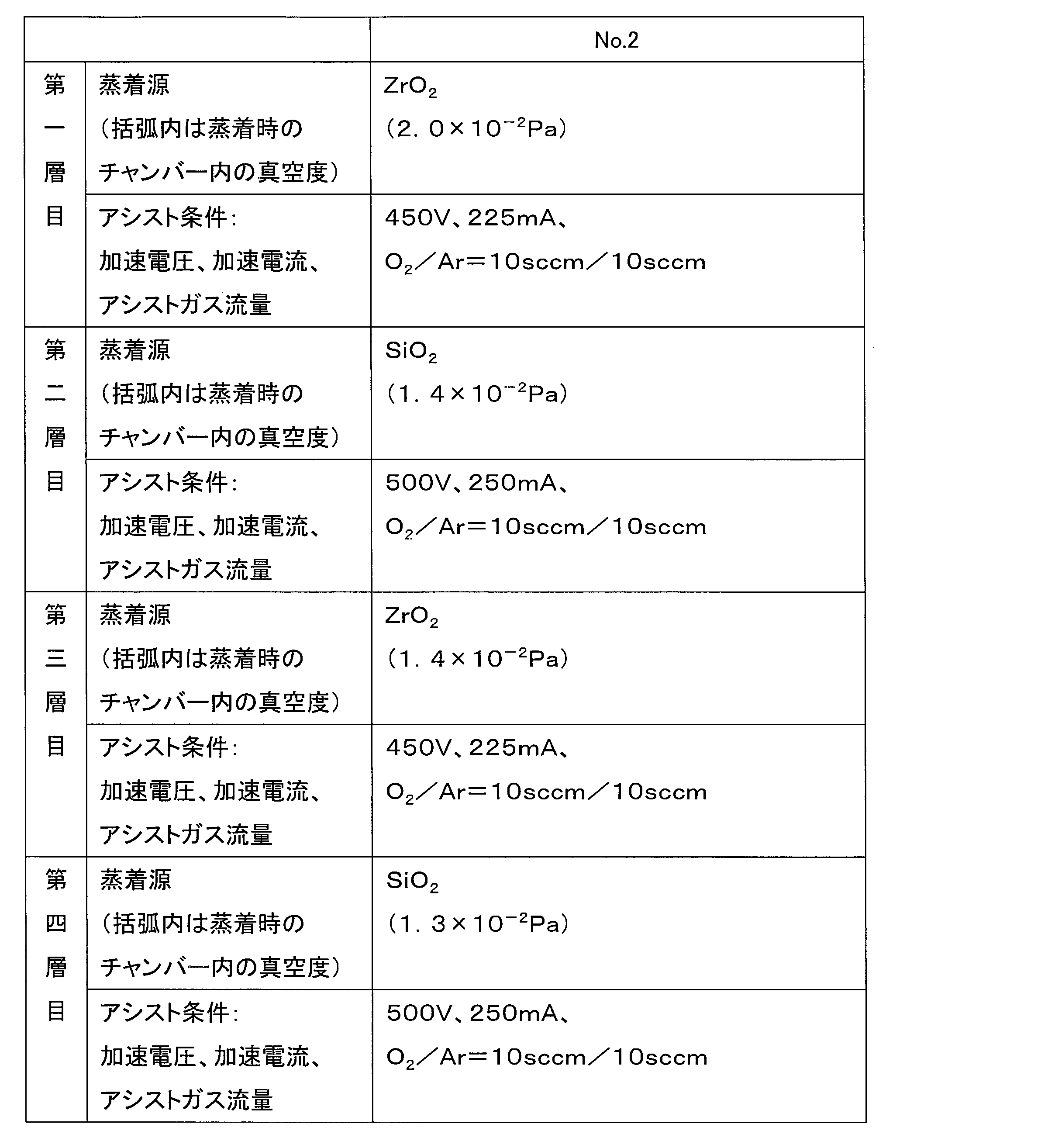
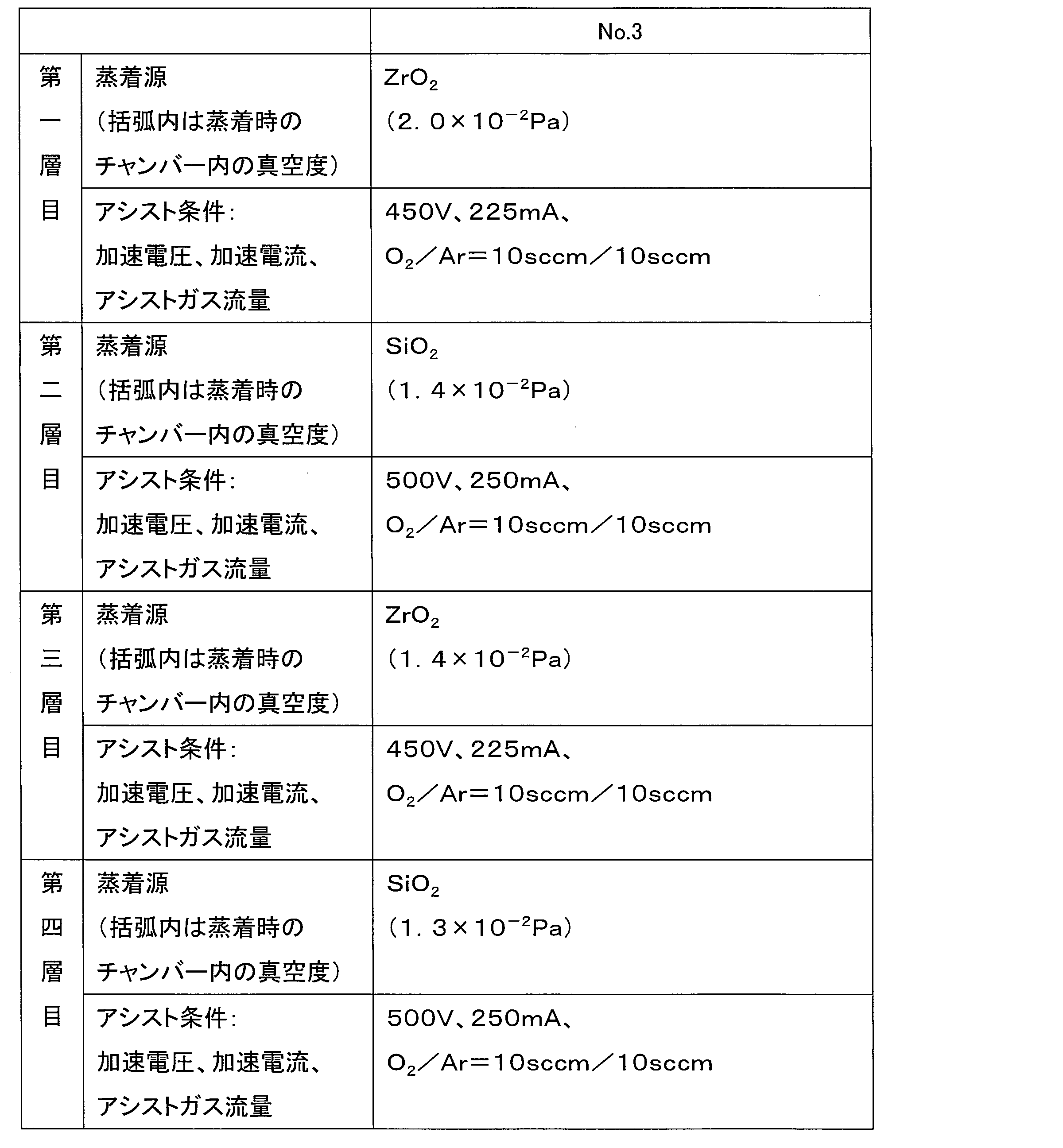
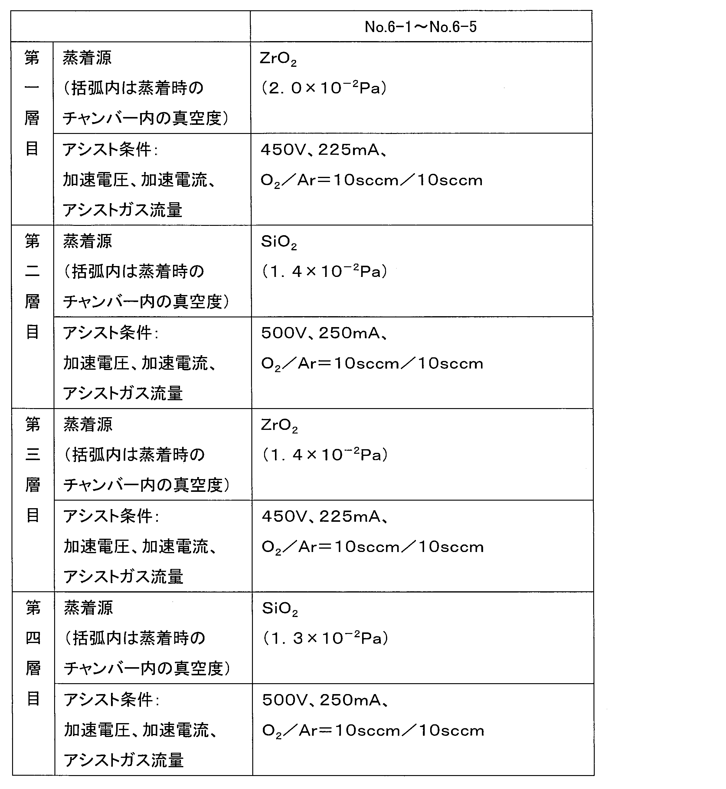
- the multilayer film is a first-layer zirconium oxide vapor-deposited film (high refractive index material layer) / second-layer silicon oxide vapor-deposited film (low-refractive index material layer) / third layer. This is composed of four layers: a zirconium oxide vapor deposition film (high refractive index material layer) / a fourth layer silicon oxide vapor deposition film (low refractive index material layer).
- the third-layer zirconium oxide deposited film is a high-refractive index material layer having the maximum thickness among the plurality of high-refractive index material layers included in the multilayer film.
- the low refractive index material layer having the maximum thickness among the plurality of low refractive index material layers is a fourth-layer silicon oxide deposited film.
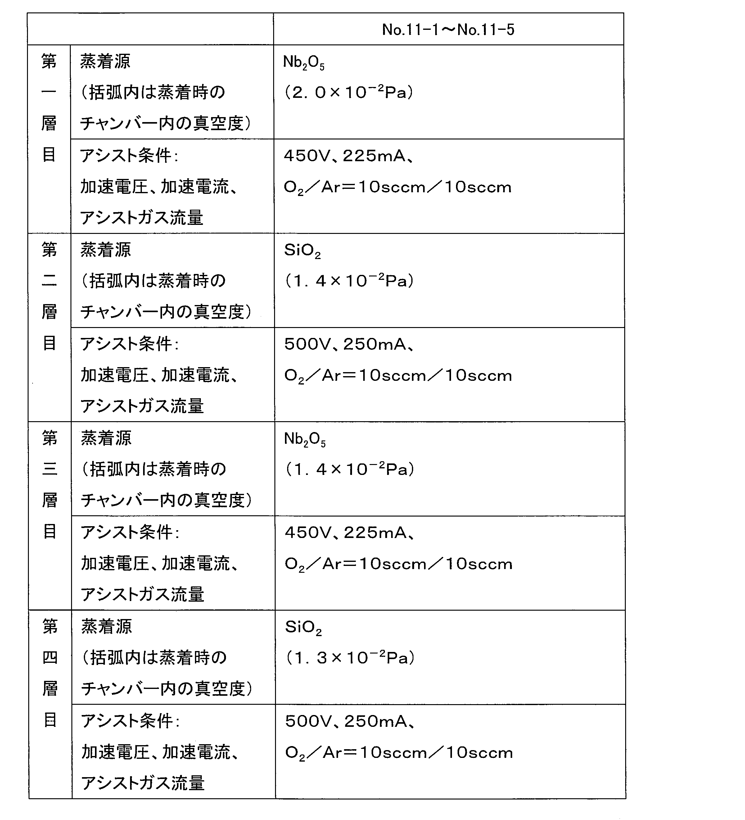
- the multilayer film is a first layer of niobium oxide vapor deposition film (high refractive index material layer) / second layer of silicon oxide vapor deposition film (low refractive index material layer) / third layer. 4 layers of a deposited film of niobium oxide (high refractive index material layer) / a deposited film of silicon oxide of the fourth layer (low refractive index material layer).
- the third layer of niobium oxide vapor deposition film is a high refractive index material layer having a maximum thickness among the plurality of high refractive index material layers included in the multilayer film.
- the low refractive index material layer having the maximum thickness among the plurality of low refractive index material layers is a fourth-layer silicon oxide deposited film.
- the multilayer film has a first layer, a second layer, a third layer, a fourth layer from the side closer to the lens substrate toward the side farther from the lens substrate. Layers can be adjacent in this order.
- the multilayer film preferably does not have a layer having a thickness of 75 nm or more containing SiO 2 as a main component as a layer closest to the lens substrate, and has a thickness of 100 nm or more containing SiO 2 as a main component. It is more preferable not to have the layer as the lens substrate side most layer.
- the spectacle lens has the multilayer film described above directly on the surface of the lens substrate, or through one or more other layers.
- the lens substrate can be a plastic lens substrate or a glass lens substrate.
- the glass lens substrate can be, for example, a lens substrate made of inorganic glass.
- a plastic lens base material is preferable from the viewpoint of being lightweight and difficult to break.
- Plastic lens base materials include (meth) acrylic resins and other styrene resins, polycarbonate resins, allyl resins, allyl carbonate resins such as diethylene glycol bisallyl carbonate resin (CR-39), vinyl resins, polyester resins, and polyether resins.
- examples thereof include a cured product (generally called a transparent resin) obtained by curing the polymerizable composition contained therein.
- a transparent resin obtained by curing the polymerizable composition contained therein.
- the lens substrate an unstained one (colorless lens) may be used, or a dyed one (stained lens) may be used.
- the refractive index of the lens substrate is, for example, about 1.50 to 1.75.
- the refractive index of the lens base material is not limited to the above range, and may be within the above range or vertically away from the above range.
- the spectacle lens may be various lenses such as a single focus lens, a multifocal lens, and a progressive power lens.
- the type of lens is determined by the surface shape of both surfaces of the lens substrate.
- the lens substrate surface may be a convex surface, a concave surface, or a flat surface.
- the object-side surface is convex and the eyeball-side surface is concave.
- the present invention is not limited to an aspect in which the object-side surface is convex and the eyeball-side surface is concave.
- the surface of the lens substrate having the multilayer film may be an object side surface, an eyeball side surface, or both the object side surface and the eyeball side surface.
- the “object side” is a side located on the object side when the spectacles equipped with spectacle lenses are worn by the wearer
- the “eye side” is the opposite, that is, This is the side located on the eyeball side when the spectacles equipped with the spectacle lens are worn by the wearer.
- the multilayer film may be directly positioned on the surface of the lens base material without interposing another layer, or may be positioned on the surface of the lens base material via one or more other layers.
- the layer that may exist between the multilayer film and the lens substrate examples include a hard coat layer, a polarizing layer, and a light control layer.
- the durability (strength) of the spectacle lens can be increased by providing a hard coat layer.
- the hard coat layer can be a cured layer formed by curing, for example, a curable composition.
- a primer layer may be formed between the multilayer film and the lens substrate.
- the primer layer can be a layer containing, for example, a resin as a main component.
- any known technique relating to spectacle lenses can be applied.
- a layer examples include various functional films such as a water-repellent or hydrophilic antifouling layer and an antifogging layer.
- Known techniques relating to spectacle lenses can also be applied to various layers that can be provided on the multilayer film.
- the further aspect of this invention can also provide the spectacles which have the spectacle lens concerning one aspect
- the spectacle lens is as detailed above. There is no restriction
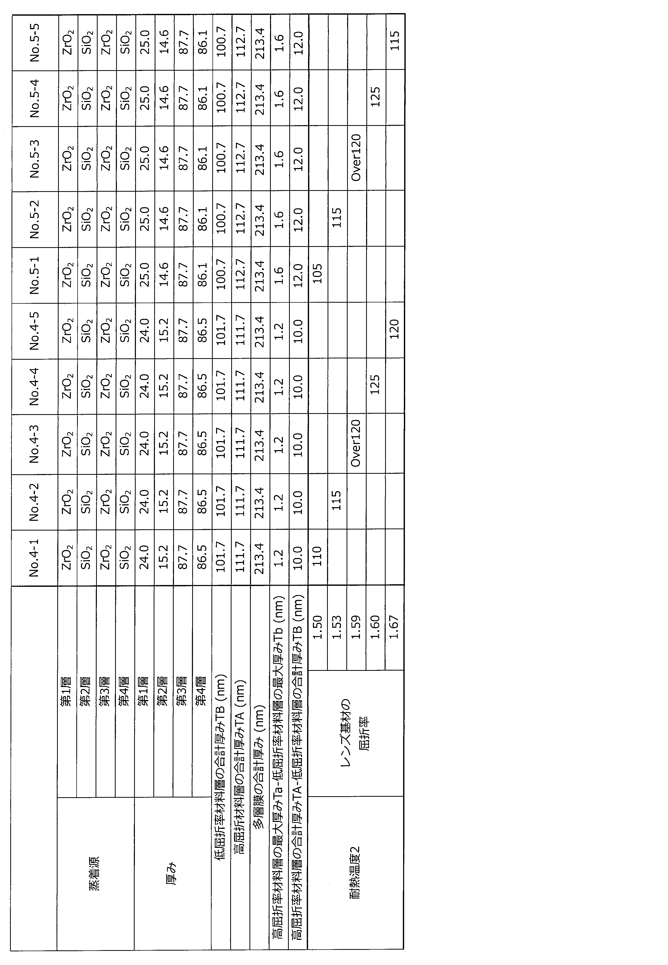
- No. 1-1-No. 11-5 is an example, and C-1 to C-7 are comparative examples.
- No. 1-1-No. 1-5 is an example in which a multilayer film having the same structure is formed on different lens substrates. This point is no. 2-1. The same applies to other embodiments such as 2-5.
- Lens base material having a refractive index of 1.50 HILUX manufactured by HOYA Corporation Lens base material having a refractive index of 1.53: Phoenix manufactured by HOYA Corporation Lens base material having a refractive index of 1.59: Poly manufactured by HOYA Corporation Lens base material having a refractive index of 1.60: Eyas manufactured by HOYA Corporation Lens substrate having a refractive index of 1.67: Eynoa manufactured by HOYA Corporation Lens base material having a refractive index of 1.70: Eyry manufactured by HOYA Corporation Lens substrate having a refractive index of 1.74: Eyvia manufactured by HOYA Corporation
- Each of the lens substrates is a plastic lens substrate having a convex surface on the object side and a concave surface on the eyeball side.
- a lens base material having a refractive index of 1.50 and a lens base material having a refractive index of 1.53 are obtained by forming a hard coat layer (cured layer of a curable composition) on both surfaces (optical surfaces) optically finished.
- a multilayer film was formed on the surface of the hard coat layer on the object side (convex surface side).
- Other lens substrates are formed on the object side (convex surface side) after a hard coat layer (cured layer of curable composition) is formed on both optically finished surfaces (optical surface) via a primer layer (resin layer).
- a multilayer film was formed on the surface of the hard coat layer.
- the multilayer film was formed by a vacuum deposition method using an ion beam assist method using oxygen gas and argon gas as an assist gas.
- a vapor deposition source a vapor deposition source composed of the oxides described in the table was used except for impurities that could inevitably be mixed.
- the refractive index of SiO 2 described in the table is 1.46
- the refractive index of ZrO 2 is 2.06, and the refractive index of Nb 2 O 5 is 2.09.
- the thickness described in the table below is a value (unit: nm) obtained by converting the optical film thickness measured by the optical film thickness measuring instrument into a physical film thickness. The thickness of each layer was controlled by the film formation time.
- KY130 manufactured by Shin-Etsu Chemical Co., Ltd. which is a fluorine-substituted alkyl group-containing organosilicon compound, is formed on the surface of the outermost vapor deposition film after forming the outermost vapor deposition film.
- vapor deposition was performed by halogen heating to form a water repellent layer.
- the spectacle lens obtained by the above process is No. 10-1 to No. 10 Except for 10 to 5, on the object side surface of the plastic lens substrate, through the hard coat layer or through the primer layer and the hard coat layer, the first high refractive index material layer, the second layer
- the low-refractive index material layer, the third high-refractive index material layer, and the fourth low-refractive index material layer have a multilayer film composed of a total of four layers adjacent in this order, and the water-repellent layer is formed on the multilayer film.
- the eyeglass lens 10-5 has a first high-refractive-index material layer, a second layer on the object-side surface of the plastic lens substrate via a hard coat layer or a primer layer and a hard coat layer.
- a multilayer film composed of a total of four layers having a low refractive index material layer, a third high refractive index material layer, and a fourth low refractive index material layer in this order,
- An ITO layer having a thickness of 5.0 nm (not counted as a multilayer film layer) is provided between the high refractive index material layer and the fourth low refractive index material layer, and a water repellent layer is formed on the multilayer film. It is a spectacle lens.
- the heat resistant temperature 1 and the heat resistant temperature 2 were measured by the following method. It can be evaluated that it is a multilayer film which is excellent in heat resistance, so that the measured heat resistant temperature is high. Since the heat resistance temperature measured by the following method is also affected by the lens substrate, the heat resistance of the multilayer film of the example and the comparative example is the heat resistance temperature 1 of the example using the same lens substrate and the comparative example 1 or The heat-resistant temperature 2 should be contrasted.
- the heat-resistant temperature 1 of each spectacle lens of Examples and Comparative Examples was measured by the following method. Each spectacle lens is put in an oven and heated for 50 minutes, and then the presence or absence of cracks in the multilayer film immediately after taking out from the oven is visually evaluated. If no crack is confirmed, it is placed in an oven heated at 5 ° C. (set temperature of the oven), heated again for 50 minutes, and then visually evaluated for the presence or absence of cracks in the multilayer film immediately after removal from the oven. The above evaluation is performed by increasing the heating temperature (set temperature of the oven) from 50 ° C. every 5 ° C., and the heating temperature when cracks are confirmed is defined as the heat resistant temperature 1 (unit: ° C.).
- this heating temperature shall be heat-resistant temperature 2 (unit: degree C).
- the evaluation of the heat resistant temperature 2 was carried out up to a heating temperature of 120 ° C. If cracks were not confirmed in the multilayer film immediately after removal from the oven even at a heating temperature of 120 ° C., the heat resistance temperature 2 was evaluated to be over 120 ° C., and “Over 120” was indicated in the table below.
- the multilayer film of the spectacle lens of the example has a higher heat resistance temperature than the multilayer film of the spectacle lens of the comparative example using the same lens base material. That is, the multilayer film included in the spectacle lens of the example is superior in heat resistance to the multilayer film included in the spectacle lens of the comparative example.
- the maximum thickness of the low refractive index material layer is thicker than the maximum thickness of the high refractive index material layer.
- the maximum thickness of the high refractive index material layer is larger than the maximum thickness of the low refractive index material layer. The present inventors speculate that this difference brings about a difference in heat resistance.
- the spectacle lenses of the examples also showed good results (evaluation results UA or A) in the alkali resistance test evaluated by the following method on the surface on the multilayer film side.
- Alkali resistance evaluation method After the eyeglass lens of the example was immersed in a 10% by mass aqueous sodium hydroxide solution (liquid temperature 20 ° C.) for 1 hour, the surface state on the multilayer film side was visually observed. From the observation results, the alkali resistance was evaluated according to the following criteria. UA: Almost no change before and after immersion A: There are several dotted film peelings on the multilayer film B: There are dotted film peelings on the entire surface of the multilayer film C: There are dotted film peelings on the entire surface of the multilayer film, There are several surface strips. D: Strips almost the entire surface of the multilayer film.
- the spectacle lens of the example showed a good result (evaluation result UA) in the durability test evaluated by the following method on the surface on the multilayer film side.
- the multilayer film of the spectacle lens of the example functions as an antireflection film exhibiting antireflection properties for light in the visible region.
- the high refractive index material layer including the refractive index material layer and having the maximum thickness among the plurality of high refractive index material layers has a low refractive index having the maximum thickness among the plurality of low refractive index material layers.
- a spectacle lens thicker than the thickness of the index material layer is provided.
- the multilayer film of the spectacle lens can exhibit excellent heat resistance. Therefore, the spectacle lens can suppress deterioration in appearance quality due to cracks in the multilayer film caused by storage or use at high temperatures.
- the total thickness of the plurality of high refractive index material layers is thicker than the total thickness of the plurality of low refractive index material layers.
- the plurality of high-refractive index material layers and the plurality of low-refractive index material layers included in the multilayer film are a first high-refractive index material layer from the side closer to the lens substrate toward the side farther from the lens substrate.
- the second low refractive index material layer, the third high refractive index material layer, and the fourth low refractive index material layer are a first high-refractive index material layer from the side closer to the lens substrate toward the side farther from the lens substrate.
- the third high refractive index material layer is a high refractive index material layer having a maximum thickness among the plurality of high refractive index material layers.
- the plurality of high refractive index material layers are zirconium oxide vapor deposition films.
- the plurality of high refractive index material layers are vapor deposition films of niobium oxide.
- the plurality of low refractive index material layers are silicon oxide vapor deposition films.
- the plurality of high-refractive index material layers and the plurality of low-refractive index material layers included in the multilayer film are a first high-refractive index material layer from the side closer to the lens substrate toward the side farther from the lens substrate.
- Zirconium oxide vapor deposition film, second low refractive index material layer silicon oxide vapor deposition film, third high refractive index material layer zirconium oxide vapor deposition film, and fourth It consists of four layers of silicon oxide vapor-deposited film, which is a low refractive index material layer.
- the third-layer zirconium oxide vapor deposition film is a high refractive index material layer having a maximum thickness among the plurality of high refractive index material layers.
- the plurality of high-refractive index material layers and the plurality of low-refractive index material layers included in the multilayer film are a first high-refractive index material layer from the side closer to the lens substrate toward the side farther from the lens substrate.
- the third layer of niobium oxide vapor deposition film is a high refractive index material layer having a maximum thickness among the plurality of high refractive index material layers.
- the thickness Ta of the high refractive index material layer having the maximum thickness among the plurality of high refractive index material layers and the thickness of the low refractive index material layer having the maximum thickness among the plurality of low refractive index material layers is 1.0 nm or more and 30.0 nm or less.
- the difference (Ta ⁇ Tb) is not less than 1.0 nm and not more than 10.0 nm.
- spectacles having the spectacle lens and a frame to which the spectacle lens is attached.
- the spectacles include a spectacle lens having a multilayer film capable of exhibiting excellent heat resistance, the multilayer film cracks due to storage or use at high temperatures, and the appearance quality of the spectacle lens deteriorates. It can suppress that the external appearance quality falls.
- the present invention is useful in the field of manufacturing eyeglass lenses and eyeglasses.
Landscapes
- Physics & Mathematics (AREA)
- Health & Medical Sciences (AREA)
- Ophthalmology & Optometry (AREA)
- General Physics & Mathematics (AREA)
- Optics & Photonics (AREA)
- General Health & Medical Sciences (AREA)
- Chemical & Material Sciences (AREA)
- Inorganic Chemistry (AREA)
- Eyeglasses (AREA)
- Engineering & Computer Science (AREA)
- Surface Treatment Of Optical Elements (AREA)
- Manufacturing & Machinery (AREA)
- Mechanical Engineering (AREA)
- Laminated Bodies (AREA)
- Physical Vapour Deposition (AREA)
Abstract
Description
レンズ基材の表面に直接または一層以上の他の層を介して多層膜を有する眼鏡レンズであって、
上記多層膜は、複数の高屈折率材料層と複数の低屈折率材料層とを含み、かつ、
上記複数の高屈折率材料層の中で最大厚みを有する高屈折率材料層の厚みは、上記複数の低屈折率材料層の中で最大厚みを有する低屈折率材料層の厚みより厚い眼鏡レンズ、
に関する。
本発明の一態様にかかる眼鏡レンズは、レンズ基材の表面に直接または一層以上の他の層を介して多層膜を有する眼鏡レンズであって、上記多層膜は、複数の高屈折率材料層と複数の低屈折率材料層とを含み、かつ、上記複数の高屈折率材料層の中で最大厚みを有する高屈折率材料層の厚みは、上記複数の低屈折率材料層の中で最大厚みを有する低屈折率材料層の厚みより厚い眼鏡レンズである。
上記眼鏡レンズは、レンズ基材の表面に直接または一層以上の他の層を介して多層膜を有する。上記多層膜には、複数の高屈折率材料層と複数の低屈折率材料層とが含まれる。本発明および本明細書において、高屈折率材料層および低屈折率材料層に関する「高」、「低」とは、相対的な表記である。即ち、高屈折率材料層とは、上記多層膜に含まれる低屈折率材料層を構成する材料の屈折率より屈折率が高い材料から構成されている層をいう。換言すれば、低屈折率材料層とは、上記多層膜に含まれる高屈折率材料層を構成する材料の屈折率より屈折率が低い材料から構成されている層をいう。本発明および本明細書において、屈折率とは、e線(波長546.07nm)に対する屈折率neをいうものとする。
高屈折率材料層を構成する高屈折率材料としては、酸化ジルコニウム(例えばZrO2)、タンタル酸化物(例えばTa2O5)、チタン酸化物(例えばTiO2)、アルミニウム酸化物(例えばAl2O3)、イットリウム酸化物(例えばY2O3)、ハフニウム酸化物(例えばHfO2)、およびニオブ酸化物(例えばNb2O5)からなる群から選ばれる酸化物の一種または二種以上の混合物を挙げることができる。
低屈折率材料層を構成する低屈折率材料としては、ケイ素酸化物(例えばSiO2)、フッ化マグネシウム(例えばMgF2)およびフッ化バリウム(例えばBaF2)からなる群から選ばれる酸化物またはフッ化物の一種または二種以上の混合物を挙げることができる。
なお上記の例示では、便宜上、酸化物およびフッ化物を化学量論組成で表示したが、化学量論組成から酸素またはフッ素が欠損もしくは過多の状態にあるものも、高屈折率材料または低屈折率材料として使用可能である。
高屈折率材料層を構成する高屈折率材料の屈折率は例えば1.60以上(例えば1.60~2.40の範囲)であり、低屈折率材料層を構成する低屈折率材料の屈折率は例えば1.59以下(例えば1.37~1.59の範囲)である。ただし上記の通り、高屈折率材料層および低屈折率材料層に関する「高」、「低」の表記は相対的なものであるため、高屈折率材料および低屈折率材料の屈折率は、上記範囲に限定されるものではない。
また、その他の高屈折率材料層の厚みは、例えば10.0~50.0nm、好ましくは10.0~40.0nm、より好ましくは15.0~30.0nmの範囲である。
一方、上記多層膜に含まれる複数の低屈折率材料層の中で最大厚みを有する低屈折率材料層の厚みは、最大厚みを有する高屈折率材料層の厚みより薄く、例えば50.0~120.0nm、好ましくは70.0~100.0nmの範囲である。
また、その他の低屈折率材料層の厚みは、例えば5.0~50.0nm、好ましくは10.0~40.0nm、より好ましくは10.0~30.0nmの範囲である。
(1)上記多層膜が、第一層目のジルコニウム酸化物の蒸着膜(高屈折率材料層)/第二層目のケイ素酸化物の蒸着膜(低屈折率材料層)/第三層目のジルコニウム酸化物の蒸着膜(高屈折率材料層)/第四層目のケイ素酸化物の蒸着膜(低屈折率材料層)、の4層からなる。更により一層好ましい一態様では、上記第三層目のジルコニウム酸化物の蒸着膜が、上記多層膜に含まれる複数の高屈折率材料層の中で最大厚みを有する高屈折率材料層である。また、一態様では、複数の低屈折率材料層の中で最大厚みを有する低屈折率材料層は、第四層目のケイ素酸化物の蒸着膜である。
(2)上記多層膜が、第一層目のニオブ酸化物の蒸着膜(高屈折率材料層)/第二層目のケイ素酸化物の蒸着膜(低屈折率材料層)/第三層目のニオブ酸化物の蒸着膜(高屈折率材料層)/第四層目のケイ素酸化物の蒸着膜(低屈折率材料層)、の4層からなる。更により一層好ましい一態様では、上記第三層目のニオブ酸化物の蒸着膜が、上記多層膜に含まれる複数の高屈折率材料層の中で最大厚みを有する高屈折率材料層である。また、一態様では、複数の低屈折率材料層の中で最大厚みを有する低屈折率材料層は、第四層目のケイ素酸化物の蒸着膜である。
上記眼鏡レンズは、以上説明した多層膜を、レンズ基材の表面に直接有するか、または一層以上の他の層を介して有する。レンズ基材は、プラスチックレンズ基材またはガラスレンズ基材であることができる。ガラスレンズ基材は、例えば無機ガラス製のレンズ基材であることができる。レンズ基材としては、軽量で割れ難いという観点から、プラスチックレンズ基材が好ましい。プラスチックレンズ基材としては、(メタ)アクリル樹脂をはじめとするスチレン樹脂、ポリカーボネート樹脂、アリル樹脂、ジエチレングリコールビスアリルカーボネート樹脂(CR-39)等のアリルカーボネート樹脂、ビニル樹脂、ポリエステル樹脂、ポリエーテル樹脂、イソシアネート化合物とジエチレングリコールなどのヒドロキシ化合物との反応で得られたウレタン樹脂、イソシアネート化合物とポリチオール化合物とを反応させたチオウレタン樹脂、分子内に1つ以上のジスルフィド結合を有する(チオ)エポキシ化合物を含有する重合性組成物を硬化した硬化物(一般に透明樹脂と呼ばれる。)を挙げることができる。レンズ基材としては、染色されていないもの(無色レンズ)を用いてもよく、染色されているもの(染色レンズ)を用いてもよい。レンズ基材の屈折率は、例えば、1.50~1.75程度である。ただしレンズ基材の屈折率は、上記範囲に限定されるものではなく、上記の範囲内でも、上記の範囲から上下に離れていてもよい。
本発明の更なる態様は、上記の本発明の一態様にかかる眼鏡レンズと、この眼鏡レンズを取り付けたフレームとを有する眼鏡を提供することもできる。眼鏡レンズについては、先に詳述した通りである。その他の眼鏡の構成については、特に制限はなく、公知技術を適用することができる。
以下に示す表中、No.1-1~No.11-5は実施例であり、C-1~C-7は比較例である。また、No.1-1~No.1-5は、同じ構成の多層膜を異なるレンズ基材上に形成した実施例である。この点は、No.2-1~No.2-5等の他の実施例についても同様である。
屈折率1.50のレンズ基材:HOYA株式会社社製Hilux
屈折率1.53のレンズ基材:HOYA株式会社社製Phoenix
屈折率1.59のレンズ基材:HOYA株式会社社製Poly
屈折率1.60のレンズ基材:HOYA株式会社社製Eyas
屈折率1.67のレンズ基材:HOYA株式会社社製Eynoa
屈折率1.70のレンズ基材:HOYA株式会社社製Eyry
屈折率1.74のレンズ基材:HOYA株式会社社製Eyvia
屈折率1.50のレンズ基材および屈折率1.53のレンズ基材は、光学的に仕上げられた両面(光学面)にハードコート層(硬化性組成物の硬化層)を形成した後、物体側(凸面側)のハードコート層表面上に多層膜を形成した。
その他のレンズ基材は、光学的に仕上げられた両面(光学面)にプライマー層(樹脂層)を介してハードコート層(硬化性組成物の硬化層)を形成した後、物体側(凸面側)のハードコート層表面上に多層膜を形成した。
多層膜は、アシストガスとして酸素ガスおよびアルゴンガスを用いて、イオンビームアシスト法を用いる真空蒸着法によって形成した。蒸着源としては、不可避的に混入する可能性のある不純物を除けば表中に記載の酸化物からなる蒸着源を使用した。表中に記載のSiO2の屈折率は1.46であり、ZrO2の屈折率は2.06であり、Nb2O5の屈折率は2.09である。また、後述の表中に記載の厚みは、光学式膜厚測定器によって測定された光学膜厚を物理膜厚に換算して求めた値(単位:nm)である。各層の厚みは成膜時間によって制御した。
また、すべての実施例および比較例には、最外層の蒸着膜を形成した後、最外層の蒸着膜の表面上に、フッ素置換アルキル基含有有機ケイ素化合物である信越化学工業株式会社製KY130およびKY500を質量%で50%:50%となるように混合した混合物を蒸着源として、ハロゲン加熱により蒸着を行い、撥水層を形成した。


No.10-1~No.10-5の眼鏡レンズは、プラスチックレンズ基材の物体側表面上に、ハードコート層を介して、またはプライマー層およびハードコート層を介して、第一層目の高屈折率材料層、第二層目の低屈折率材料層、第三層目の高屈折率材料層および第四層目の低屈折率材料層をこの順に有する合計4層からなる多層膜を有し、第三層目の高屈折率材料層と第四層目の低屈折率材料層との間に厚み5.0nmのITO層(多層膜の層としてはカウントされない)を有し、この多層膜上に撥水層を有する眼鏡レンズである。
以下の方法により、耐熱温度1および耐熱温度2を測定した。測定された耐熱温度が高いほど、耐熱性に優れる多層膜であると評価することができる。以下の方法により測定される耐熱温度はレンズ基材の影響も受けるため、実施例と比較例の多層膜の耐熱性については、同じレンズ基材を用いた実施例と比較例の耐熱温度1または耐熱温度2を対比すべきである。
実施例および比較例の各眼鏡レンズの耐熱温度1を、以下の方法によって測定した。
各眼鏡レンズをオーブンに入れて50分間加熱した後、オーブンから取りだした直後の多層膜におけるクラックの有無を目視で評価する。クラックが確認されなければ、5℃昇温(オーブンの設定温度)したオーブンに入れて再び50分間加熱した後、オーブンから取りだした直後の多層膜におけるクラックの有無を目視で評価する。
上記評価を、加熱温度(オーブンの設定温度)を、50℃から5℃毎に昇温して行い、クラックが確認されたときの加熱温度を耐熱温度1(単位:℃)とする。
実施例および比較例の各眼鏡レンズの耐熱温度2を、以下の方法によって測定した。
各眼鏡レンズをオーブンに入れて50分間加熱した後、オーブンから取り出した直後の多層膜におけるクラックの有無を目視で評価する。クラックが確認されなければ、5℃昇温(オーブンの設定温度)したオーブンに入れて再び50分間加熱した後、オーブンから取りだした直後の多層膜におけるクラックの有無を目視で評価する。
上記評価を、加熱温度(オーブンの設定温度)を、50℃から5℃毎に昇温して行い、オーブンから取り出した直後の多層膜においてクラックが確認されたら、その眼鏡レンズを引き続き室温下で30分間放置した後に多層膜におけるクラックの有無を目視で評価する。ここでクラックが確認されたら、この加熱温度を耐熱温度2(単位:℃)とする。耐熱温度2の評価は、加熱温度120℃まで実施した。加熱温度120℃でもオーブンから取り出した直後の多層膜においてクラックが確認されなければ、耐熱温度2は120℃超であると評価し、以下の表中に「Over 120」と示した。


実施例の眼鏡レンズを10質量%水酸化ナトリウム水溶液(液温20℃)に1時間浸漬した後、多層膜側の表面状態を目視で観察した。観察結果から、以下の基準により耐アルカリ性を評価した。
UA:浸漬前後で殆ど変化なし
A:多層膜に点状の膜剥げが数個あり
B:多層膜の全面に点状の膜剥げあり
C:多層膜の全面に点状の膜剥げがあり、面状の膜剥げも数個あり
D:多層膜の殆ど全面で膜剥げ
実施例の眼鏡レンズの物体側表面上(多層膜を有する表面上)で1kgの荷重をかけたスチールウールを20往復させた後、多層膜表面の傷の発生の程度を目視で観察した。観察結果から、以下の基準により耐久性を評価した。
UA:多層膜表面に傷がまったく確認されない。
A:多層膜表面にごく浅い傷がわずかに観察される。
B:多層膜表面に線状の傷が1~2本観察される。
C:多層膜表面に線状の傷が3本以上観察される。
D:多層膜表面が重度にダメージを受けている。
Claims (10)
- レンズ基材の表面に直接または一層以上の他の層を介して多層膜を有する眼鏡レンズであって、
前記多層膜は、複数の高屈折率材料層と複数の低屈折率材料層とを含み、かつ、
前記複数の高屈折率材料層の中で最大厚みを有する高屈折率材料層の厚みは、前記複数の低屈折率材料層の中で最大厚みを有する低屈折率材料層の厚みより厚い眼鏡レンズ。 - 前記複数の高屈折率材料層の合計厚みは、前記複数の低屈折率材料層の合計厚みより厚い、請求項1に記載の眼鏡レンズ。
- 前記多層膜に含まれる複数の高屈折率材料層および複数の低屈折率材料層は、前記レンズ基材に近い側から遠い側に向かって、
第一層目の高屈折率材料層、
第二層目の低屈折率材料層、
第三層目の高屈折率材料層、および
第四層目の低屈折率材料層、
の4層からなる、請求項1または2に記載の眼鏡レンズ。 - 前記第三層目の高屈折率材料層が、前記複数の高屈折率材料層の中で最大厚みを有する高屈折率材料層である、請求項3に記載の眼鏡レンズ。
- 前記複数の高屈折率材料層はジルコニウム酸化物の蒸着膜である、請求項1~4のいずれか1項に記載の眼鏡レンズ。
- 前記複数の高屈折率材料層はニオブ酸化物の蒸着膜である、請求項1~4のいずれか1項に記載の眼鏡レンズ。
- 前記複数の低屈折率材料層はケイ素酸化物の蒸着膜である、請求項1~6のいずれか1項に記載の眼鏡レンズ。
- 前記複数の高屈折率材料層の中で最大厚みを有する高屈折率材料層の厚みTaと前記複数の低屈折率材料層の中で最大厚みを有する低屈折率材料層の厚みTbとの差分(Ta-Tb)は、1.0nm以上30.0nm以下である、請求項1~7のいずれか1項に記載の眼鏡レンズ。
- 前記差分(Ta-Tb)は、1.0nm以上10.0nm以下である、請求項8に記載の眼鏡レンズ。
- 請求項1~9のいずれか1項に記載の眼鏡レンズと、該眼鏡レンズを取り付けたフレームと、を有する眼鏡。
Priority Applications (5)
| Application Number | Priority Date | Filing Date | Title |
|---|---|---|---|
| JP2018535706A JPWO2018038114A1 (ja) | 2016-08-22 | 2017-08-22 | 眼鏡レンズおよび眼鏡 |
| CN201780005131.0A CN108431678A (zh) | 2016-08-22 | 2017-08-22 | 眼镜镜片及眼镜 |
| KR1020187018050A KR20180078328A (ko) | 2016-08-22 | 2017-08-22 | 안경 렌즈 및 안경 |
| EP17843592.1A EP3505997A4 (en) | 2016-08-22 | 2017-08-22 | EYEWEAR AND GLASSES |
| US16/018,423 US20180299700A1 (en) | 2016-08-22 | 2018-06-26 | Spectacle lens and spectacles |
Applications Claiming Priority (2)
| Application Number | Priority Date | Filing Date | Title |
|---|---|---|---|
| JP2016161996 | 2016-08-22 | ||
| JP2016-161996 | 2016-08-22 |
Related Child Applications (1)
| Application Number | Title | Priority Date | Filing Date |
|---|---|---|---|
| US16/018,423 Continuation US20180299700A1 (en) | 2016-08-22 | 2018-06-26 | Spectacle lens and spectacles |
Publications (1)
| Publication Number | Publication Date |
|---|---|
| WO2018038114A1 true WO2018038114A1 (ja) | 2018-03-01 |
Family
ID=61246105
Family Applications (1)
| Application Number | Title | Priority Date | Filing Date |
|---|---|---|---|
| PCT/JP2017/029977 WO2018038114A1 (ja) | 2016-08-22 | 2017-08-22 | 眼鏡レンズおよび眼鏡 |
Country Status (6)
| Country | Link |
|---|---|
| US (1) | US20180299700A1 (ja) |
| EP (1) | EP3505997A4 (ja) |
| JP (1) | JPWO2018038114A1 (ja) |
| KR (1) | KR20180078328A (ja) |
| CN (1) | CN108431678A (ja) |
| WO (1) | WO2018038114A1 (ja) |
Cited By (1)
| Publication number | Priority date | Publication date | Assignee | Title |
|---|---|---|---|---|
| WO2019031325A1 (ja) * | 2017-08-08 | 2019-02-14 | 日東電工株式会社 | 反射防止フィルム |
Families Citing this family (2)
| Publication number | Priority date | Publication date | Assignee | Title |
|---|---|---|---|---|
| US10672652B2 (en) * | 2018-06-29 | 2020-06-02 | Taiwan Semiconductor Manufacturing Co., Ltd. | Gradient atomic layer deposition |
| US11231533B2 (en) * | 2018-07-12 | 2022-01-25 | Visera Technologies Company Limited | Optical element having dielectric layers formed by ion-assisted deposition and method for fabricating the same |
Citations (12)
| Publication number | Priority date | Publication date | Assignee | Title |
|---|---|---|---|---|
| US5719705A (en) * | 1995-06-07 | 1998-02-17 | Sola International, Inc. | Anti-static anti-reflection coating |
| US20120028005A1 (en) * | 2010-07-30 | 2012-02-02 | Essilor International (Compagnie Generale D'optique) | Optical Article Including an Antireflecting Coating Having Antifog Properties and Process for Making Same |
| JP2012027322A (ja) * | 2010-07-26 | 2012-02-09 | Nitto Denko Corp | 反射防止層付き円偏光板および画像表示装置 |
| JP2012062244A (ja) * | 2003-08-13 | 2012-03-29 | Saint-Gobain Glass France | 反射防止膜を含む透明基板 |
| WO2013183457A1 (ja) * | 2012-06-08 | 2013-12-12 | 旭硝子株式会社 | 光学素子 |
| JP2014032330A (ja) * | 2012-08-03 | 2014-02-20 | Ricoh Imaging Co Ltd | ハーフミラー及びデジタル一眼レフカメラ |
| WO2014050930A1 (ja) * | 2012-09-28 | 2014-04-03 | 株式会社ニコン・エシロール | 光学部品およびその製造方法 |
| JP2014240997A (ja) * | 2012-02-17 | 2014-12-25 | 株式会社ニコン・エシロール | 眼鏡レンズ用光学部品、眼鏡レンズ用光学部品の製造方法 |
| JP2015152735A (ja) * | 2014-02-13 | 2015-08-24 | 東海光学株式会社 | 光学製品並びに眼鏡レンズ及び眼鏡 |
| WO2015137282A1 (ja) * | 2014-03-14 | 2015-09-17 | ホヤ レンズ タイランド リミテッド | ミラーコートレンズ |
| JP2016029474A (ja) * | 2014-07-16 | 2016-03-03 | 旭硝子株式会社 | カバーガラス |
| JP2016080857A (ja) * | 2014-10-16 | 2016-05-16 | リコーイメージング株式会社 | 反射防止膜、それを用いた光学部材、及び光学機器 |
Family Cites Families (4)
| Publication number | Priority date | Publication date | Assignee | Title |
|---|---|---|---|---|
| JP2012093689A (ja) * | 2010-09-29 | 2012-05-17 | Nikon-Essilor Co Ltd | 光学部品およびその製造方法 |
| US10359552B2 (en) * | 2011-01-17 | 2019-07-23 | University Of Utah Research Foundation | Methods, systems, and apparatus for reducing the frequency and/or severity of photophobic responses or for modulating circadian cycles |
| JPWO2015080160A1 (ja) * | 2013-11-26 | 2017-03-16 | ホヤ レンズ タイランド リミテッドHOYA Lens Thailand Ltd | 眼鏡レンズ |
| CA2969346C (en) * | 2014-12-01 | 2021-03-23 | Hoya Lens Thailand Ltd. | Spectacle lens and spectacles |
-
2017
- 2017-08-22 EP EP17843592.1A patent/EP3505997A4/en not_active Withdrawn
- 2017-08-22 JP JP2018535706A patent/JPWO2018038114A1/ja active Pending
- 2017-08-22 CN CN201780005131.0A patent/CN108431678A/zh active Pending
- 2017-08-22 KR KR1020187018050A patent/KR20180078328A/ko not_active IP Right Cessation
- 2017-08-22 WO PCT/JP2017/029977 patent/WO2018038114A1/ja active Application Filing
-
2018
- 2018-06-26 US US16/018,423 patent/US20180299700A1/en not_active Abandoned
Patent Citations (12)
| Publication number | Priority date | Publication date | Assignee | Title |
|---|---|---|---|---|
| US5719705A (en) * | 1995-06-07 | 1998-02-17 | Sola International, Inc. | Anti-static anti-reflection coating |
| JP2012062244A (ja) * | 2003-08-13 | 2012-03-29 | Saint-Gobain Glass France | 反射防止膜を含む透明基板 |
| JP2012027322A (ja) * | 2010-07-26 | 2012-02-09 | Nitto Denko Corp | 反射防止層付き円偏光板および画像表示装置 |
| US20120028005A1 (en) * | 2010-07-30 | 2012-02-02 | Essilor International (Compagnie Generale D'optique) | Optical Article Including an Antireflecting Coating Having Antifog Properties and Process for Making Same |
| JP2014240997A (ja) * | 2012-02-17 | 2014-12-25 | 株式会社ニコン・エシロール | 眼鏡レンズ用光学部品、眼鏡レンズ用光学部品の製造方法 |
| WO2013183457A1 (ja) * | 2012-06-08 | 2013-12-12 | 旭硝子株式会社 | 光学素子 |
| JP2014032330A (ja) * | 2012-08-03 | 2014-02-20 | Ricoh Imaging Co Ltd | ハーフミラー及びデジタル一眼レフカメラ |
| WO2014050930A1 (ja) * | 2012-09-28 | 2014-04-03 | 株式会社ニコン・エシロール | 光学部品およびその製造方法 |
| JP2015152735A (ja) * | 2014-02-13 | 2015-08-24 | 東海光学株式会社 | 光学製品並びに眼鏡レンズ及び眼鏡 |
| WO2015137282A1 (ja) * | 2014-03-14 | 2015-09-17 | ホヤ レンズ タイランド リミテッド | ミラーコートレンズ |
| JP2016029474A (ja) * | 2014-07-16 | 2016-03-03 | 旭硝子株式会社 | カバーガラス |
| JP2016080857A (ja) * | 2014-10-16 | 2016-05-16 | リコーイメージング株式会社 | 反射防止膜、それを用いた光学部材、及び光学機器 |
Non-Patent Citations (1)
| Title |
|---|
| See also references of EP3505997A4 * |
Cited By (1)
| Publication number | Priority date | Publication date | Assignee | Title |
|---|---|---|---|---|
| WO2019031325A1 (ja) * | 2017-08-08 | 2019-02-14 | 日東電工株式会社 | 反射防止フィルム |
Also Published As
| Publication number | Publication date |
|---|---|
| JPWO2018038114A1 (ja) | 2018-09-27 |
| EP3505997A4 (en) | 2020-04-01 |
| KR20180078328A (ko) | 2018-07-09 |
| CN108431678A (zh) | 2018-08-21 |
| EP3505997A1 (en) | 2019-07-03 |
| US20180299700A1 (en) | 2018-10-18 |
Similar Documents
| Publication | Publication Date | Title |
|---|---|---|
| JP6530765B2 (ja) | 眼鏡レンズおよび眼鏡 | |
| JP6415587B2 (ja) | 眼鏡レンズおよび眼鏡 | |
| JP7265983B2 (ja) | 眼鏡レンズおよび眼鏡 | |
| KR20180094151A (ko) | 안경 렌즈 | |
| WO2018038114A1 (ja) | 眼鏡レンズおよび眼鏡 | |
| JP7136909B2 (ja) | 眼鏡レンズ | |
| KR102582202B1 (ko) | 안경 렌즈 | |
| KR102685727B1 (ko) | 안경 렌즈 | |
| JP2023182008A (ja) | 眼鏡レンズ | |
| US11860452B2 (en) | Spectacle lens and spectacles | |
| JP2023182010A (ja) | 眼鏡レンズ | |
| JP2022157712A (ja) | 眼鏡レンズ及び眼鏡 | |
| JP2023182009A (ja) | 眼鏡レンズ |
Legal Events
| Date | Code | Title | Description |
|---|---|---|---|
| WWE | Wipo information: entry into national phase |
Ref document number: 2018535706 Country of ref document: JP |
|
| ENP | Entry into the national phase |
Ref document number: 20187018050 Country of ref document: KR Kind code of ref document: A |
|
| 121 | Ep: the epo has been informed by wipo that ep was designated in this application |
Ref document number: 17843592 Country of ref document: EP Kind code of ref document: A1 |
|
| NENP | Non-entry into the national phase |
Ref country code: DE |
|
| WWE | Wipo information: entry into national phase |
Ref document number: 2017843592 Country of ref document: EP |