WO2018037809A1 - 固形燃料の製造方法 - Google Patents
固形燃料の製造方法 Download PDFInfo
- Publication number
- WO2018037809A1 WO2018037809A1 PCT/JP2017/026685 JP2017026685W WO2018037809A1 WO 2018037809 A1 WO2018037809 A1 WO 2018037809A1 JP 2017026685 W JP2017026685 W JP 2017026685W WO 2018037809 A1 WO2018037809 A1 WO 2018037809A1
- Authority
- WO
- WIPO (PCT)
- Prior art keywords
- coal
- solid fuel
- fuel
- ratio
- compression molding
- Prior art date
- Legal status (The legal status is an assumption and is not a legal conclusion. Google has not performed a legal analysis and makes no representation as to the accuracy of the status listed.)
- Ceased
Links
Images
Classifications
-
- C—CHEMISTRY; METALLURGY
- C10—PETROLEUM, GAS OR COKE INDUSTRIES; TECHNICAL GASES CONTAINING CARBON MONOXIDE; FUELS; LUBRICANTS; PEAT
- C10L—FUELS NOT OTHERWISE PROVIDED FOR; NATURAL GAS; SYNTHETIC NATURAL GAS OBTAINED BY PROCESSES NOT COVERED BY SUBCLASSES C10G OR C10K; LIQUIFIED PETROLEUM GAS; USE OF ADDITIVES TO FUELS OR FIRES; FIRE-LIGHTERS
- C10L5/00—Solid fuels
- C10L5/02—Solid fuels such as briquettes consisting mainly of carbonaceous materials of mineral or non-mineral origin
- C10L5/04—Raw material of mineral origin to be used; Pretreatment thereof
-
- C—CHEMISTRY; METALLURGY
- C10—PETROLEUM, GAS OR COKE INDUSTRIES; TECHNICAL GASES CONTAINING CARBON MONOXIDE; FUELS; LUBRICANTS; PEAT
- C10L—FUELS NOT OTHERWISE PROVIDED FOR; NATURAL GAS; SYNTHETIC NATURAL GAS OBTAINED BY PROCESSES NOT COVERED BY SUBCLASSES C10G OR C10K; LIQUIFIED PETROLEUM GAS; USE OF ADDITIVES TO FUELS OR FIRES; FIRE-LIGHTERS
- C10L5/00—Solid fuels
- C10L5/02—Solid fuels such as briquettes consisting mainly of carbonaceous materials of mineral or non-mineral origin
- C10L5/06—Methods of shaping, e.g. pelletizing or briquetting
- C10L5/08—Methods of shaping, e.g. pelletizing or briquetting without the aid of extraneous binders
Definitions
- the present invention relates to a method for producing a solid fuel.
- Powdered fuel has a relatively small bulk density and is likely to disappear due to scattering, so that the handling cost is likely to increase and there is a risk of causing dust pollution. For this reason, powdered fuel is compressed and molded into granular (briquette) for easy handling.
- reformed coal obtained by heating and dehydrating low-grade coal such as lignite in oil is usually in the form of powder, so it is desired to granulate by compression molding.
- low-grade coal such as lignite in oil
- compression molding it is necessary to perform compression molding at a considerably high pressure, which not only increases the manufacturing cost but also causes insufficient pressure to convey There is a risk of causing powdery troubles along the way.
- an object of the present invention is to provide a method for producing a solid fuel from which a solid fuel having a relatively high strength can be obtained.
- the invention made in order to solve the above-mentioned problems is a method for producing a solid fuel by compression-molding a coal-based powdered fuel, and is bound to the coal-based powdered fuel with a higher binding property than the coal-based powdered fuel.
- a step of mixing the pulverized coal a step of supplying the mixture obtained in the mixing step to the compression molding machine using a supply hopper having a supply screw, and a step of compression molding the mixture by the compression molding machine.
- the ratio of the loose bulk density to the hard bulk density of the mixture is 0.8 or less, and the space corresponding to the lower part of the execution part of the supply screw with respect to the spatial volume of the upper part of the supply part of the supply screw of the supply hopper.
- the method for producing the solid fuel has a ratio of the loose bulk density to the solid bulk density of the mixture within the above range, and an execution part of the supply screw with respect to a space volume corresponding to one upper end of the execution part of the supply screw of the supply hopper.
- the ratio of the space volume of one lower end of the execution part of the supply screw to the space volume of the upper end of the supply part of the supply screw of the supply hopper is 0.
- the ratio of the loose bulk density to the solid bulk density of the mixture 6 times or more and 0.9 times or less are preferable.
- the ratio of the space volume of the lower part of the execution part of the supply screw to the space volume of the upper part of the execution part of the supply screw of the supply hopper is within the above range, thereby compressing the mixture of raw materials.
- the amount supplied to the molding machine can be made more appropriate, and the strength of the obtained solid fuel can be increased.
- the mixing step it is preferable to further mix a part of the solid fuel obtained in the compression molding step.
- the mixing step by further mixing the pulverized part of the solid fuel obtained in the compression molding step, the ratio of the loose bulk density to the hard bulk density of the mixture can be made relatively easy.
- the average particle diameter of the pulverized solid fuel mixed in the mixing step is preferably 1 mm or more and 8 mm or less.
- the pressure in the compression molding machine can be increased more reliably.
- modified coal obtained by heating and dehydrating low-grade coal in oil may be used, and low-grade coal powder may be used as the binding powder coal.
- low-grade coal powder may be used as the binding powder coal.
- “high binding property” means that “crushing strength” measured in accordance with JIS-Z8841 (1993) when compression molding under the same conditions is high.
- “Loose bulk density” means the apparent specific gravity of a granular material containing a large amount of air that has been dropped by an injection method (a method of dropping powder through a funnel-shaped member) and received in a container.
- the “hard bulk density” means the apparent specific gravity of a powder obtained by tapping 180 times of a powder containing a large amount of air obtained by an injection method.
- the “loose bulk density” and the “hard bulk density” can be measured using, for example, “Powder Tester PT-S type” manufactured by Hosokawa Micron.
- the “average particle diameter” means a sieve opening with a mass integrated value of 50% in a particle size distribution obtained by a sieving test according to JIS-Z8815 (1994).
- the method for producing a solid fuel can produce a solid fuel having a relatively high strength from a powder fuel.
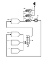
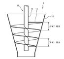
- FIG. 1 It is a schematic diagram which shows the structure of the manufacturing apparatus used for the manufacturing method of the solid fuel of one Embodiment of this invention. It is a typical detailed sectional view of the supply hopper of FIG.
- FIG. 1 shows a schematic configuration of a solid fuel production apparatus used in a solid fuel production method according to an embodiment of the present invention.
- 1 is an apparatus for obtaining granular solid fuel by compressing and molding coal-based powdered fuel.
- the solid fuel production apparatus of FIG. 1 includes a first silo 1 that stores coal-based powdered fuel, a second silo 2 that stores binding powdered coal having a higher binding property than coal-based powdered fuel, and a coal-based powdered fuel. And a third silo 3 for storing pulverized fuel having an average particle size larger than that.
- the solid fuel production apparatus of FIG. 1 includes a mixer 4 that mixes coal-based powdered fuel, binding powdered coal, and pulverized fuel supplied from silos 1, 2, and 3, and a raw material discharged from the mixer 4. And an intermediate silo 5 for storing the mixture.
- the solid fuel production apparatus of FIG. 1 has a raw material supply hopper 6 that temporarily holds the raw material mixture discharged from the intermediate silo 5, and the raw material mixture is supplied from the raw material supply hopper 6. And a compression molding machine 7 for compressing and molding the desired solid fuel.
- the 1 further includes a pulverizer 8 for pulverizing a part of the solid fuel formed by the compression molding machine 7.
- the solid fuel pulverized by the pulverizer 8 is supplied to the third silo 3 as the pulverized fuel.
- the conveyance of the granular material (coal-based powdered fuel, binding powdered coal, pulverized fuel, and solid fuel) between components should be performed by a known technique such as a chute, a belt conveyor, a bucket conveyor, or a pneumatic conveyor. Can do.
- the method for producing the solid fuel that can be performed using the solid fuel production apparatus as described above includes a step of mixing the binding powdered coal and the pulverized fuel with the coal-based powder fuel by the mixer 4 ⁇ mixing step>
- coal-based powdered fuel, binding powdered coal and pulverized fuel are supplied from the silos 1, 2 and 3 to the mixer 4, and the mixer 4 mixes these coal-based powdered fuel, binding powdered coal and pulverized fuel.
- a raw material mixture is obtained.
- the raw material mixture obtained in this way is transferred to the intermediate silo 5 and stored in the intermediate silo 5.
- coal-based powder fuel examples include modified coal (Upgraded Brown Coal, etc.) obtained by heating and dehydrating small coal, such as pulverized coal and low-grade coal (subbituminous coal and lignite), in oil. Etc. can be used.
- the manufacturing method of the said solid fuel can manufacture a granular solid fuel by using as a main raw material the reformed coal which was not easy to granulate conventionally.
- Binding pulverized coal As the binding pulverized coal, pulverized coal having a higher binding property than that of the coal-based pulverized fuel may be used, but in order to suppress an increase in cost, it is preferable to use a relatively low-grade pulverized coal.
- the lower limit of the 20% particle diameter D20 of the binding coal powder is preferably 0.005 mm, and more preferably 0.010 mm.
- the upper limit of the 90% particle diameter D90 of the binding coal powder is preferably 3 mm, and more preferably 1 mm.
- Pulverized fuel As the pulverized fuel, a pulverized solid fuel finally obtained by the solid fuel production method is used.
- the lower limit of the average particle size of the pulverized fuel is preferably 1 mm, and more preferably 2 mm.
- the upper limit of the average particle diameter of the pulverized fuel is preferably 8 mm, and more preferably 6 mm. If the average particle size of the pulverized fuel is less than the lower limit, the compression moldability of the raw material mixture may not be sufficiently improved. On the other hand, when the average particle size of the pulverized fuel exceeds the above upper limit, the miscibility with the coal-based powder fuel becomes insufficient, and the strength of the obtained solid fuel may vary.
- the lower limit of the 20% particle diameter D20 of the pulverized fuel is preferably 0.5 mm, and more preferably 1 mm.
- the upper limit of the 90% particle diameter D90 of the pulverized fuel is preferably 10 mm, and more preferably 7 mm.
- the lower limit of the bulk density of the raw material mixture obtained by mixing coal-based powdered fuel, binding powdered coal and pulverized fuel is preferably 0.5 g / cc, more preferably 0.6 g / cc.
- the upper limit of the bulk density of the raw material mixture is preferably 1.0 g / cc, more preferably 0.9 g / cc. If the bulk density of the raw material mixture is less than the above lower limit, the raw material mixture may not be sufficiently filled into the cavity of the compression molding machine 7 to be described later, and the raw material mixture may not be compression-molded. There is a possibility that the strength of is insufficient. On the other hand, when the solid bulk density of the raw material mixture exceeds the above upper limit, the filling of the raw material mixture into the cavity of the compression molding machine 7 may be excessive, which may cause an overload of the compression molding machine 7.
- the lower limit of the ratio of the loose bulk density to the solid bulk density of the raw material mixture (hereinafter sometimes referred to as bulk density ratio) is preferably 0.5, and more preferably 0.55.
- the upper limit of the bulk density ratio is 0.8, preferably 0.75. If the bulk density ratio is less than the above lower limit, the raw material mixture may not be sufficiently filled into the cavity of the compression molding machine 7 and the raw material mixture may not be compression molded, and the strength of the solid fuel obtained is insufficient There is a risk of becoming. On the other hand, when the bulk density ratio exceeds the upper limit, filling of the raw material mixture into the cavity of the compression molding machine 7 may be excessive and cause overloading of the compression molding machine 7.
- the lower limit of the mixing ratio of the binding coal powder in the raw material mixture is preferably 5% by mass, and more preferably 8% by mass.
- the upper limit of the mixing ratio of the binding coal powder is preferably 30% by mass, and more preferably 25% by mass.
- the lower limit of the mixing ratio of the pulverized fuel in the raw material mixture is preferably 5% by mass, and more preferably 8% by mass.
- the upper limit of the mixing ratio of the pulverized fuel is preferably 50% by mass, and more preferably 40% by mass.
- the mixing ratio of the pulverized fuel is less than the lower limit, the strength of the solid fuel may not be sufficiently improved.
- the mixing ratio of the pulverized fuel exceeds the above upper limit, the production efficiency of the solid fuel may be unnecessarily lowered, and the strength of the solid fuel obtained by forming gaps between the particles of the pulverized fuel becomes insufficient. There is a fear.
- silos 1, 2, 3, and 5 coal-based powdered fuel, binding powdered coal, pulverized fuel, and a raw material mixture obtained by mixing these may be respectively stored and discharged as necessary. .
- the first silo 1 for storing coal-based powdered fuel, the third silo 3 for storing pulverized fuel, and the intermediate silo 5 for storing raw material mixture can be configured to be able to have a nitrogen atmosphere inside.
- the first silo 1, the third silo 3 and the intermediate silo 5 are provided with a measurement mechanism for measuring the carbon dioxide (CO 2 ) concentration inside, and when the CO 2 concentration measured by the measurement mechanism increases. It is preferable to include a gas supply mechanism for introducing nitrogen gas (N 2 ).
- the mixer 4 only needs to be able to uniformly mix coal-based powdered fuel, binding powdered coal, and pulverized fuel.
- a mixer that rotates a container a mixer having stirring blades, or the like can be used. It may be a continuous type or a continuous type.
- things, such as a V type and a double cone type are mentioned, for example.
- examples of the mixer having a stirring blade include a paddle mixer and a ribbon mixer.
- the mixing time (residence time) of the raw material by the mixer 4 is generally preferably 30 minutes or less when the mixer 4 is a paddle mixer, for example. Mixing is required.
- the degree of mixing of raw materials can be evaluated by, for example, collecting samples after mixing in small amounts and observing the variation in moisture. When the moisture value varies widely, mixing is insufficient, so it can be determined that the mixing time by the mixer 4 needs to be increased.
- the raw material mixture is discharged from the intermediate silo 5 and supplied to the compression molding machine 7 while compressing the raw material mixture using the supply hopper 6.
- the supply hopper 6 includes a supply hopper body 10 and a supply screw 11 that rotates within the supply hopper body 10.
- the supply hopper 6 is connected to the raw material charging port of the compression molding machine 7 and supplies the raw material mixture to the compression molding machine 7 while compressing the raw material mixture by the supply screw 11.
- the supply hopper main body 10 has at least an execution portion (a portion where the raw material mixture is compressed by the supply screw 11) formed in a cylindrical shape or a conical shape.
- the supply screw 11 has a rotary shaft 12 concentric with the execution unit of the supply hopper main body 10 and screw fins 13 arranged in a spiral shape on the outer periphery of the rotary shaft 12.
- the supply hopper 6 has a space volume corresponding to one rotation of the supply screw 11 (from the internal volume of the supply hopper main body 10 to the supply screw 11) by the diameter reduction of the supply hopper main body 10 and the change in the pitch of the screw fins 13 of the supply screw 11.
- the volume obtained by subtracting the volume of is configured to gradually decrease.
- screw space volume ratio As a lower limit of the ratio of the space volume of one execution portion lower end of the supply screw 11 to the space volume of one execution portion upper end of the supply screw 11 of the supply hopper 6 (hereinafter referred to as screw space volume ratio), 0.3 And 0.35 is preferable.
- the upper limit of the screw space volume ratio is 0.6, preferably 0.55.
- the screw space volume ratio is less than the lower limit, the supply of the raw material mixture to the compression molding machine 7 becomes excessive, and the compression molding machine 7 may be overloaded.
- the screw space volume ratio exceeds the upper limit, a sufficient amount of the raw material mixture cannot be supplied to the cavity of the compression molding machine 7 to be described later, and the strength of the solid fuel may be insufficient.
- the screw fin 13 of the supply screw 11 is less than two rounds, the space volume for one round of the execution unit upper end and the space volume for one round of the execution unit lower end are partly calculated. .
- the lower limit of the ratio of the screw space volume ratio of the feed hopper 6 to the bulk density ratio of the raw material mixture is preferably 0.6, and more preferably 0.65.
- the upper limit of the ratio of the screw space volume ratio of the supply hopper 6 to the bulk density ratio of the raw material mixture is preferably 0.9, more preferably 0.85.
- Examples of the compression molding machine 7 used in the compression molding process include a double roll molding machine and a tableting molding machine.
- a double roll molding machine having a relatively large processing capability is preferably used.
- the double roll molding machine has a structure in which a pair of cylindrical rolls are horizontally adjacent to each other, and the rolls rotate in a direction from above to an adjacent point. A large number of cavities are provided on the outer peripheral surface of the pair of rolls so as to face each other and rotate synchronously. Thereby, a double roll molding machine can compress a granular material between opposing cavities, and can shape
- pulverization step a part of the solid fuel obtained in the compression molding step is pulverized by the pulverizer 8 to obtain the above pulverized fuel.
- the pulverized fuel thus obtained is transferred to the third silo 3 and stored.
- the bulk density of the raw material mixture to be subjected to compression molding can be made larger than that of the coal-based powder fuel.
- the pulverizer 8 is not particularly limited, and a known rotary cutter, hammer mill, or the like can be used.
- a sieve for separating large-diameter particles in the fuel may be provided, and the separated large-diameter particles may be re-supplied to the pulverizer 8.
- the ratio of the loose bulk density to the bulk density of the mixture is within the above range, and the supply screw 11 is executed with respect to the space volume corresponding to one round of the upper end of the supply screw 11 of the supply hopper 6.
- the raw material mixture can be supplied to the compression molding machine 7 at a relatively high density by setting the ratio of the space volume for one round at the lower end of the part within the above range. For this reason, since the raw material mixture can be compression-molded by applying a sufficient pressure by the compression molding machine 7 in the method for producing the solid fuel, a solid fuel having a relatively high strength can be produced.
- the pulverized fuel may not be mixed in the mixing step. That is, the raw material mixture supplied from the supply hopper to the compression molding machine may not include the pulverized fuel.
- the strength of the solid fuel obtained in the compression molding process is measured, and the mixing ratio of the binding coal powder, the operation speed of the compression molding machine, etc. are determined according to the strength of the solid fuel. You may adjust.
- a measuring method of measuring the strength of the solid fuel for example, a compression fracture test, a tensile test, an impact test, a drop test, or the like can be employed.
- Example 1 a modified coal powder obtained by heating and dehydrating lignite coal in oil is used as the coal-based powder fuel, and a pulverized coal powder pulverized and passed through a sieve having a mesh opening of 3 mm is used as the binding powder coal.
- the raw material mixture was obtained by mixing coal-based powdered fuel and binding powdered coal at a mass ratio of 90:10.
- the loose bulk density and the hard bulk density of this raw material mixture were measured using, for example, “Powder Tester PT-S type” manufactured by Hosokawa Micron Corporation.
- the loose bulk density was 0.50 g / cc
- the solid bulk density was 0.72 g / cc.
- the raw material mixture was supplied to a compression molding machine using a supply hopper having a screw space volume ratio of 0.52.
- a compression molding machine a double roll molding machine “K-4020” manufactured by Furukawa Industries Systems Co., Ltd. was used, and a roll with a diameter of 1 m having a cavity having a major axis of 42 mm, a minor axis of 24 mm, and a volume of 15 cc was mounted.
- the raw material mixture was compression molded by this compression molding machine to obtain a granular solid fuel.
- the compression molding machine could be stably operated at a speed at which the production amount was 10 ton / h. Further, the crushing strength of the obtained solid fuel was measured according to JIS-Z8841 (1993) and found to be 100 kgf.
- Example 2 A mixture of coal-based powdered fuel similar to that in Example 1 and binder powdered coal at a mass ratio of 80:10 is the same as that in Example 1 using a supply hopper having a screw space volume ratio of 0.47.
- the granular solid fuel obtained by supplying to the compression molding machine was pulverized and passed through a sieve having an opening of 10 mm as a pulverized fuel.
- Coal-based powdered fuel, binding powdered coal, and pulverized fuel were mixed at a mass ratio of 80:10:10 to obtain a raw material mixture.
- Example 3 A solid fuel was produced under the same conditions as in Example 1 except that a feed hopper having a screw space volume ratio of 0.40 was used. The production amount at this time was 7.5 ton / h, and the crushing strength of the obtained solid fuel was 120 kgf.
- Example 4 A solid fuel was produced under the same conditions as in Example 2 except that a feed hopper having a screw space volume ratio of 0.58 was used. The production amount at this time was 12 ton / h, and the crushing strength of the obtained solid fuel was 68 kgf.
- Example 1 A mixture of coal-based powdered fuel similar to that in Example 1 and binding powdered coal at a mass ratio of 20:20 is used in the same manner as in Example 1 using a supply hopper having a screw space volume ratio of 0.60.
- the granular solid fuel obtained by supplying to the compression molding machine was pulverized and passed through a sieve having an opening of 10 mm as a pulverized fuel.
- Coal-based powdered fuel, binding powdered coal, and pulverized fuel were mixed at a mass ratio of 20:20:60 to obtain a raw material mixture.
- the loose bulk density of the raw material mixture was 0.82 g / cc
- the solid bulk density was 0.88 g / cc.
- Comparative Example 2 A raw material mixture was obtained under the same conditions as in Example 1 except that a feed hopper with a screw space volume ratio of 0.15 was used, and this raw material mixture was compression molded with a compression molding machine. The machine stopped due to overload and solid fuel could not be obtained.
- Example 3 A solid fuel was produced under the same conditions as in Example 1 except that a feed hopper having a screw space volume ratio of 0.80 was used. The production amount at this time was 12 ton / h, and the crushing strength of the obtained solid fuel was 15 kgf. Moreover, the obtained solid fuel was not formed sufficiently densely, and the shape was incomplete.
- Table 1 summarizes the results of Examples 1 to 4 and Comparative Examples 1 to 3.
- the table also shows the ratio of the loose bulk density to the bulk density of the raw material mixture (bulk density ratio) and the ratio of the screw space volume ratio to the bulk density ratio.
- Example 1 in which the ratio of the screw space volume ratio to the bulk density ratio was within a preferable range was higher in productivity than Example 3 in which the ratio of the screw space volume ratio to the bulk density ratio was slightly smaller.
- Example 2 in which the ratio of the screw space volume ratio to the bulk density ratio is within a preferable range, the strength of the solid fuel obtained is higher than that in Example 4 in which the ratio of the screw space volume ratio to the bulk density ratio is slightly larger. It was.
- Comparative Example 1 where the bulk density ratio is too large and Comparative Example 2 where the screw space volume ratio is too small, the compression molding machine is overloaded, and in Comparative Example 3 where the screw space volume ratio is too large, the strength of the obtained solid fuel is low. It was enough.
- the method for producing a solid fuel according to the present invention can be suitably used for producing a granular solid fuel using a coal-based powder fuel having inferior compression moldability as a raw material.
Landscapes
- Chemical & Material Sciences (AREA)
- Life Sciences & Earth Sciences (AREA)
- Environmental & Geological Engineering (AREA)
- General Life Sciences & Earth Sciences (AREA)
- Geochemistry & Mineralogy (AREA)
- Geology (AREA)
- Oil, Petroleum & Natural Gas (AREA)
- Organic Chemistry (AREA)
- Solid Fuels And Fuel-Associated Substances (AREA)
Abstract
本発明は、比較的強度の大きい固形燃料が得られる固形燃料の製造方法を提供することを課題とする。本発明に係る固形燃料の製造方法は、石炭系粉末燃料を圧縮成型する固形燃料の製造方法であって、上記石炭系粉末燃料に、この石炭系粉末燃料よりも結着性が大きい結着性粉炭を混合する工程と、供給スクリューを有する供給ホッパーを用いて上記混合工程で得られる混合体を圧縮成型機に供給する工程と、圧縮成型機で上記混合体を圧縮成型する工程とを備え、上記混合体の固めかさ密度に対する緩めかさ密度の比が0.8以下であり、上記供給ホッパーの供給スクリューの実行部上端1周分の空間体積に対する供給スクリューの実行部下端1周分の空間体積の比が0.3以上0.6以下である。
Description
本発明は、固形燃料の製造方法に関する。
粉末燃料は、比較的嵩密度が小さいことや飛散により消失しやすいことから、ハンドリングコストが増大しやすく、粉塵公害を引き起こすおそれもある。このため、粉末燃料を粒状(ブリケット)に圧縮成型して取り扱いやすくすることが行われている。
例えば褐炭等の低品位炭を油中で加熱脱水して得られる改質炭は、通常は粉末状となるため、圧縮成型して粒状化することが望まれる。しかしながら、炭化度の低い低品位炭から得られる改質炭を成型するためにはかなりの高圧で圧縮成型する必要があり、製造コストが上昇するだけでなく、加圧が不十分となって搬送途中に粉化するトラブルが生じるおそれがある。
これに対して、改質炭を加湿して加圧成型することで、得られる固形燃料の強度を向上する技術が提案されている(特開2010-116544号公報参照)。しかしながら、上記公報に記載の方法でも、固形燃料の使用やハンドリングの態様によっては粉化が生じるおそれがある。
上記不都合に鑑みて、本発明は、比較的強度の大きい固形燃料が得られる固形燃料の製造方法を提供することを課題とする。
上記課題を解決するためになされた発明は、石炭系粉末燃料を圧縮成型する固形燃料の製造方法であって、上記石炭系粉末燃料に、この石炭系粉末燃料よりも結着性が大きい結着性粉炭を混合する工程と、供給スクリューを有する供給ホッパーを用いて上記混合工程で得られる混合体を圧縮成型機に供給する工程と、圧縮成型機で上記混合体を圧縮成型する工程とを備え、上記混合体の固めかさ密度に対する緩めかさ密度の比が0.8以下であり、上記供給ホッパーの供給スクリューの実行部上端1周分の空間体積に対する供給スクリューの実行部下端1周分の空間体積の比が0.3以上0.6以下である固形燃料の製造方法である。
当該固形燃料の製造方法は、上記混合体の固めかさ密度に対する緩めかさ密度の比を上記範囲内とし、かつ上記供給ホッパーの供給スクリューの実行部上端1周分の空間体積に対する供給スクリューの実行部下端1周分の空間体積の比を上記範囲内とすることによって、原料の混合体を圧縮成型機に比較的高密度に供給することができる。このため、当該固形燃料の製造方法は、圧縮成型機により十分な圧力を加えて原料の混合体を圧縮成型することができるので、比較的強度の大きい固形燃料を製造することができる。
上記供給ホッパーの供給スクリューの実行部上端1周分の空間体積に対する供給スクリューの実行部下端1周分の空間体積の比としては、上記混合体の固めかさ密度に対する緩めかさ密度の比の0.6倍以上0.9倍以下が好ましい。このように、上記供給ホッパーの供給スクリューの実行部上端1周分の空間体積に対する供給スクリューの実行部下端1周分の空間体積の比を上記範囲内とすることによって、原料の混合体の圧縮成型機への供給量をより適切化することができ、得られる固形燃料の強度をより大きくすることができる。
上記混合工程で、上記圧縮成型工程で得られる固形燃料の一部を粉砕したものをさらに混合するとよい。このように、上記混合工程で、上記圧縮成型工程で得られる固形燃料の一部を粉砕したものをさらに混合することによって、上記混合体の固めかさ密度に対する緩めかさ密度の比を比較的容易に上記範囲内とすることができる。
上記混合工程で混合する粉砕した固形燃料の平均粒子径としては、1mm以上8mm以下が好ましい。このように、上記混合工程で混合する粉砕した固形燃料の平均粒子径が上記範囲内であることによって、圧縮成型機における圧力をより確実に大きくすることができる。
上記石炭系粉末燃料として低品位炭を油中で加熱脱水して得られる改質炭を用い、上記結着性粉炭として低品位炭の粉末を用いるとよい。このように、上記石炭系粉末燃料として低品位炭を油中で加熱脱水して得られる改質炭を用い、上記結着性粉炭として低品位炭の粉末を用いることによって、比較的安価で高品質な固形燃料を提供することができる。
なお、「結着性が大きい」とは、同じ条件で圧縮成型した場合にJIS-Z8841(1993)に準拠して測定される「圧壊強度」が大きいことを意味する。また。「緩めかさ密度」とは、注入法(ロート状の部材を通して粉体を落下させる方法)により落下させて容器に受けてできた多量に空気を含んだ粉粒体の見掛比重を意味する。また、「固めかさ密度」とは、注入法によって得られた多量に空気を含んだ粉粒体を180回タッピングして固めた粉粒体の見掛比重を意味する。なお、「緩めかさ密度」及び「固めかさ密度」は、例えばホソカワミクロン社の「パウダテスタPT-S型」を用いて測定することができる。また、「平均粒子径」とは、JIS-Z8815(1994)に準拠した篩分け試験により得られる粒度分布において、質量積算値が50%となる篩の目開きを意味する。
以上のように、当該固形燃料の製造方法は、粉末燃料から比較的強度の大きい固形燃料を製造することができる。
以下、適宜図面を参照しつつ、本発明の実施の形態を詳説する。
[固形燃料製造装置]
図1に、本発明の一実施形態に係る固形燃料の製造方法に用いられる固形燃料製造装置の概略構成を示す。
図1に、本発明の一実施形態に係る固形燃料の製造方法に用いられる固形燃料製造装置の概略構成を示す。
図1の固形燃料製造装置は、石炭系粉末燃料を圧縮成型することにより粒状の固形燃料を得るための装置である。
図1の固形燃料製造装置は、石炭系粉末燃料を貯留する第1サイロ1と、石炭系粉末燃料よりも結着性が大きい結着性粉炭を貯留する第2サイロ2と、石炭系粉末燃料よりも平均粒子径が大きい粉砕燃料を貯留する第3サイロ3とを備える。
また、図1の固形燃料製造装置は、サイロ1、2、3から供給される石炭系粉末燃料、結着性粉炭及び粉砕燃料を混合する混合機4と、この混合機4から排出される原料混合体を貯留する中間サイロ5とを備える。
また、図1の固形燃料製造装置は、中間サイロ5から排出される原料混合体を一時的に保留する原料供給ホッパー6と、この原料供給ホッパー6から原料混合体が供給され、この原料混合体を圧縮成型して目的の固形燃料とする圧縮成型機7とを備える。
さらに、図1の固形燃料製造装置は、圧縮成型機7が形成した固形燃料の一部を粉砕する粉砕機8を備える。粉砕機8により粉砕された固形燃料は、上記粉砕燃料として第3サイロ3に供給されるようになっている。また、構成要素間の粉粒体(石炭系粉末燃料、結着性粉炭、粉砕燃料及び固形燃料)の搬送は、例えばシュート、ベルトコンベア、バケットコンベア、ニューマチックコンベア等、周知の技術によって行うことができる。
以上のような固形燃料製造装置を使用して行うことができる当該固形燃料の製造方法は、混合機4により石炭系粉末燃料に結着性粉炭及び粉砕燃料を混合する工程<混合工程>と、供給ホッパー6を用いて原料混合体を圧縮成型機7に供給する工程<供給工程>と、圧縮成型機7で原料混合体を圧縮成型する工程<圧縮成型工程>と、この圧縮成型工程で得られる固形燃料の一部を粉砕する工程<粉砕工程>とを備える。
<混合工程>
混合工程では、サイロ1、2、3から石炭系粉末燃料、結着性粉炭及び粉砕燃料を混合機4に供給し、混合機4によりこれら石炭系粉末燃料、結着性粉炭及び粉砕燃料を混合して原料混合体を得る。これにより得られる原料混合体は、中間サイロ5に移送されて、中間サイロ5に貯留される。
混合工程では、サイロ1、2、3から石炭系粉末燃料、結着性粉炭及び粉砕燃料を混合機4に供給し、混合機4によりこれら石炭系粉末燃料、結着性粉炭及び粉砕燃料を混合して原料混合体を得る。これにより得られる原料混合体は、中間サイロ5に移送されて、中間サイロ5に貯留される。
(石炭系粉末燃料)
固形燃料の主原料である石炭系粉末燃料としては、例えば小径の石炭である粉炭、低品位炭(亜瀝青炭や褐炭)を油中で加熱脱水して得られる改質炭(Upgraded Brown Coal等)などを用いることができる。中でも、当該固形燃料の製造方法は、従来は粒状化が容易ではなかった改質炭を主原料として粒状の固形燃料を製造することができる。
固形燃料の主原料である石炭系粉末燃料としては、例えば小径の石炭である粉炭、低品位炭(亜瀝青炭や褐炭)を油中で加熱脱水して得られる改質炭(Upgraded Brown Coal等)などを用いることができる。中でも、当該固形燃料の製造方法は、従来は粒状化が容易ではなかった改質炭を主原料として粒状の固形燃料を製造することができる。
(結着性粉炭)
結着性粉炭としては、石炭系粉末燃料よりも結着性が大きい粉炭を用いればよいが、コスト増大を抑制するために、比較的安価な低品位炭の粉砕炭を用いることが好ましい。
結着性粉炭としては、石炭系粉末燃料よりも結着性が大きい粉炭を用いればよいが、コスト増大を抑制するために、比較的安価な低品位炭の粉砕炭を用いることが好ましい。
結着性粉炭の20%粒子径D20の下限としては、0.005mmが好ましく、0.010mmがより好ましい。結着性粉炭の20%粒子径D20が上記下限に満たない場合、発塵等により結着性粉炭のハンドリングが難しくなるおそれがある。一方、結着性粉炭の90%粒子径D90の上限としては、3mmが好ましく、1mmがより好ましい。結着性粉炭の90%粒子径D90が上記上限を超える場合、石炭系粉末燃料との混合性が不十分となることで得られる固形燃料の強度がばらつくおそれがある。なお、「20%粒子径D20」及び「90%粒子径D90」とは、JIS-Z8815(1994)に準拠した篩分け試験において、篩下の累積質量が全粒子の質量の20%になったときの篩の目の大きさ及び90%になったときの篩の目の大きさを意味する。
(粉砕燃料)
粉砕燃料としては、当該固形燃料の製造方法によって最終的に得られる固形燃料を粉砕機8により粉砕したものを使用する。
粉砕燃料としては、当該固形燃料の製造方法によって最終的に得られる固形燃料を粉砕機8により粉砕したものを使用する。
粉砕燃料の平均粒子径の下限としては、1mmが好ましく、2mmがより好ましい。一方、粉砕燃料の平均粒子径の上限としては、8mmが好ましく、6mmがより好ましい。粉砕燃料の平均粒子径が上記下限に満たない場合、原料混合体の圧縮成型性を十分に向上できないおそれがある。逆に、粉砕燃料の平均粒子径が上記上限を超える場合、石炭系粉末燃料との混合性が不十分となって、得られる固形燃料の強度がばらつくおそれがある。
また、粉砕燃料の20%粒子径D20の下限としては、0.5mmが好ましく、1mmがより好ましい。粉砕燃料の20%粒子径D20が上記下限に満たない場合、原料混合体の圧縮成型性を十分に向上できないおそれがある。一方、粉砕燃料の90%粒子径D90の上限としては、10mmが好ましく、7mmがより好ましい。粉砕燃料の90%粒子径D90が上記上限を超える場合、石炭系粉末燃料との混合性が不十分となって、得られる固形燃料の強度がばらつくおそれがある。
(原料混合体)
石炭系粉末燃料、結着性粉炭及び粉砕燃料を混合して得られる原料混合体の固めかさ密度の下限としては、0.5g/ccが好ましく、0.6g/ccがより好ましい。一方、原料混合体の固めかさ密度の上限としては、1.0g/ccが好ましく、0.9g/ccがより好ましい。原料混合体の固めかさ密度が上記下限に満たない場合、後述する圧縮成型機7のキャビティへの原料混合体の充填が不十分となって原料混合体を圧縮成型できないおそれや、得られる固形燃料の強度が不十分となるおそれがある。逆に、原料混合体の固めかさ密度が上記上限を超える場合、圧縮成型機7のキャビティへの原料混合体の充填が過剰となって圧縮成型機7の過負荷の原因となるおそれがある。
石炭系粉末燃料、結着性粉炭及び粉砕燃料を混合して得られる原料混合体の固めかさ密度の下限としては、0.5g/ccが好ましく、0.6g/ccがより好ましい。一方、原料混合体の固めかさ密度の上限としては、1.0g/ccが好ましく、0.9g/ccがより好ましい。原料混合体の固めかさ密度が上記下限に満たない場合、後述する圧縮成型機7のキャビティへの原料混合体の充填が不十分となって原料混合体を圧縮成型できないおそれや、得られる固形燃料の強度が不十分となるおそれがある。逆に、原料混合体の固めかさ密度が上記上限を超える場合、圧縮成型機7のキャビティへの原料混合体の充填が過剰となって圧縮成型機7の過負荷の原因となるおそれがある。
原料混合体の固めかさ密度に対する緩めかさ密度の比(以下、かさ密度比ということがある)の下限としては、0.5が好ましく、0.55がより好ましい。一方、上記かさ密度比の上限としては、0.8であり、0.75が好ましい。上記かさ密度比が上記下限に満たない場合、圧縮成型機7のキャビティへの原料混合体の充填が不十分となって原料混合体を圧縮成型できないおそれや、得られる固形燃料の強度が不十分となるおそれがある。逆に、上記かさ密度比が上記上限を超える場合、圧縮成型機7のキャビティへの原料混合体の充填が過剰となって圧縮成型機7の過負荷の原因となるおそれがある。
原料混合体における結着性粉炭の混合比(原料混合体全体に対する比率)の下限としては、5質量%が好ましく、8質量%がより好ましい。一方、結着性粉炭の混合比の上限としては、30質量%が好ましく、25質量%がより好ましい。結着性粉炭の混合比が上記下限に満たない場合、固形燃料の強度を十分に向上できないおそれがある。逆に、結着性粉炭の混合比が上記上限を超える場合、固形燃料の価格が不必要に増大するおそれある。
原料混合体における粉砕燃料の混合比の下限としては、5質量%が好ましく、8質量%がより好ましい。一方、粉砕燃料の混合比の上限としては、50質量%が好ましく、40質量%がより好ましい。粉砕燃料の混合比が上記下限に満たない場合、固形燃料の強度を十分に向上できないおそれがある。逆に、粉砕燃料の混合比が上記上限を超える場合、固形燃料の製造効率が不必要に低下するおそれや、粉砕燃料の粒子間に隙間ができることで得られる固形燃料の強度が不十分となるおそれがある。
(サイロ)
サイロ1、2、3、5としては、石炭系粉末燃料、結着性粉炭、粉砕燃料及びこれらを混合した原料混合体をそれぞれ貯留し、必要に応じて排出することができるものであればよい。
サイロ1、2、3、5としては、石炭系粉末燃料、結着性粉炭、粉砕燃料及びこれらを混合した原料混合体をそれぞれ貯留し、必要に応じて排出することができるものであればよい。
中でも、石炭系粉末燃料を貯留する第1サイロ1、粉砕燃料を貯留する第3サイロ3及び原料混合体を貯留する中間サイロ5は、内部を窒素雰囲気とすることができるよう構成されることが好ましい。より詳しくは、第1サイロ1、第3サイロ3及び中間サイロ5は、内部の二酸化炭素(CO2)濃度を測定する測定機構と、測定機構が測定したCO2濃度が上昇した場合に内部に窒素ガス(N2)を導入するガス供給機構とを備えるものとすることが好ましい。
(混合機)
混合機4としては、石炭系粉末燃料、結着性粉炭及び粉砕燃料を均等に混合できるものであればよく、例えば容器を回転するミキサー、撹拌羽根を有するミキサー等を用いることができ、バッチ式のものであっても連続式のものであってもよい。容器を回転するミキサーとしては、例えばV型、ダブルコーン型等のものが挙げられる。一方、撹拌羽根を有するミキサーとしては、例えばパドルミキサー、リボンミキサー等が挙げられる。また、混合機4として、動力を用いず、重力により落下する粉粒体を例えば固定撹拌羽根等を用いて混合する静的混合機を使用してもよい。
混合機4としては、石炭系粉末燃料、結着性粉炭及び粉砕燃料を均等に混合できるものであればよく、例えば容器を回転するミキサー、撹拌羽根を有するミキサー等を用いることができ、バッチ式のものであっても連続式のものであってもよい。容器を回転するミキサーとしては、例えばV型、ダブルコーン型等のものが挙げられる。一方、撹拌羽根を有するミキサーとしては、例えばパドルミキサー、リボンミキサー等が挙げられる。また、混合機4として、動力を用いず、重力により落下する粉粒体を例えば固定撹拌羽根等を用いて混合する静的混合機を使用してもよい。
混合機4による原料の混合時間(滞留時間)としては、例として混合機4がパドルミキサーである場合、一般的には30分以下が望ましいが、これに限ったものではなく、原料を均等に混合することが必要とされる。原料の混合度合いは、例えば混合後のサンプルを少量ずつ採取し、その水分ばらつきを見ることで評価できる。水分値にばらつきが大きい場合は混合が不十分なので、混合機4による混合時間を大きくする必要があるものと判断できる。
<供給工程>
供給工程では、中間サイロ5から原料混合体を排出し、供給ホッパー6を用いて原料混合体を圧縮しつつ圧縮成型機7に供給する。
供給工程では、中間サイロ5から原料混合体を排出し、供給ホッパー6を用いて原料混合体を圧縮しつつ圧縮成型機7に供給する。
(供給ホッパー)
供給ホッパー6は、図2に示すように、供給ホッパー本体10と、この供給ホッパー本体10内で回転する供給スクリュー11とを有する。この供給ホッパー6は、圧縮成型機7の原料投入口に接続され、供給スクリュー11により原料混合体を圧縮しつつ圧縮成型機7に供給する。
供給ホッパー6は、図2に示すように、供給ホッパー本体10と、この供給ホッパー本体10内で回転する供給スクリュー11とを有する。この供給ホッパー6は、圧縮成型機7の原料投入口に接続され、供給スクリュー11により原料混合体を圧縮しつつ圧縮成型機7に供給する。
供給ホッパー本体10は、少なくとも実行部(供給スクリュー11により原料混合体を圧縮する部分)が円筒状又は円錐状に形成される。
供給スクリュー11は、供給ホッパー本体10の実行部と同心の回転軸12と、この回転軸12の外周にらせん状に配設されるスクリューフィン13とを有する。
供給ホッパー6は、供給ホッパー本体10の縮径と、供給スクリュー11のスクリューフィン13のピッチの変化とによって、供給スクリュー11の1周分の空間体積(供給ホッパー本体10の内容積から供給スクリュー11の体積を減じた容積)が徐々に減少するよう構成される。
供給ホッパー6の供給スクリュー11の実行部上端1周分の空間体積に対する供給スクリュー11の実行部下端1周分の空間体積の比(以下、スクリュー空間体積比という)の下限としては、0.3であり、0.35が好ましい。一方、上記スクリュー空間体積比の上限としては、0.6であり、0.55が好ましい。上記スクリュー空間体積比が上記下限に満たない場合、圧縮成型機7への原料混合体の供給が過剰となることで圧縮成型機7が過負荷となるおそれがある。逆に、上記スクリュー空間体積比が上記上限を超える場合、後述する圧縮成型機7のキャビティに十分な量の原料混合体を供給することができず、固形燃料の強度が不足するおそれがある。なお、供給スクリュー11のスクリューフィン13が2周未満である場合、上記実行部上端1周分の空間体積と、上記実行部下端1周分の空間体積とは一部が重複して算出される。
供給ホッパー6のスクリュー空間体積比の原料混合体のかさ密度比に対する比率の下限としては、0.6が好ましく、0.65がより好ましい。一方、供給ホッパー6のスクリュー空間体積比の原料混合体のかさ密度比に対する比率の上限としては、0.9が好ましく、0.85がより好ましい。供給ホッパー6のスクリュー空間体積比の原料混合体のかさ密度比に対する比率が上記下限に満たない場合、圧縮成型機7への原料混合体の供給が過剰となることで圧縮成型機7が過負荷となるおそれがある。逆に、供給ホッパー6のスクリュー空間体積比の原料混合体のかさ密度比に対する比率が上記上限を超える場合、圧縮成型機7への原料混合体の供給が不十分となることで固形燃料の強度が不足するおそれがある。
<圧縮成型工程>
圧縮成型工程では、圧縮成型機7を用いて原料混合体を圧縮成型することにより、粒状の固形燃料を得る。
圧縮成型工程では、圧縮成型機7を用いて原料混合体を圧縮成型することにより、粒状の固形燃料を得る。
(圧縮成型機)
圧縮成型工程で用いる圧縮成型機7としては、例えばダブルロール成型機、打錠成型機等が挙げられ、中でも比較的処理能力が大きいダブルロール成型機が好適に用いられる。ダブルロール成型機は、一対の円筒形のロールが水平に隣接する構造となっており、ロールが上方から隣接点に向かう方向に回転する。この一対のロールの外周表面には、多数のキャビティが一対のロールの間で対向しかつ同期回転するよう設けられる。これにより、ダブルロール成型機は、対向するキャビティ間で粉粒体を圧縮して粒状に成型することができる。
圧縮成型工程で用いる圧縮成型機7としては、例えばダブルロール成型機、打錠成型機等が挙げられ、中でも比較的処理能力が大きいダブルロール成型機が好適に用いられる。ダブルロール成型機は、一対の円筒形のロールが水平に隣接する構造となっており、ロールが上方から隣接点に向かう方向に回転する。この一対のロールの外周表面には、多数のキャビティが一対のロールの間で対向しかつ同期回転するよう設けられる。これにより、ダブルロール成型機は、対向するキャビティ間で粉粒体を圧縮して粒状に成型することができる。
また、特に圧縮成型機7としてダブルロール成型機を用いる場合、圧縮成型された粒状体だけでなく、原料混合体が成型されることなく一対のロールの隙間を通過して排出され得る。また、何らかの原因でキャビティへの原料混合体の供給が不十分となり、十分に圧縮されず粉化する場合もある。このため、成型されず排出される原料混合体を分離する篩を圧縮成型機7の直後に設けてもよい。成型された固形燃料から分離された原料混合体は、中間サイロ5に再供給すればよい。
<粉砕工程>
粉砕工程では、圧縮成型工程で得られる固形燃料の一部を粉砕機8で粉砕することにより、上述の粉砕燃料を得る。これにより得られた粉砕燃料は、第3サイロ3に移送されて貯留される。
粉砕工程では、圧縮成型工程で得られる固形燃料の一部を粉砕機8で粉砕することにより、上述の粉砕燃料を得る。これにより得られた粉砕燃料は、第3サイロ3に移送されて貯留される。
この粉砕工程で得られる粉砕燃料を石炭系粉末燃料に混合することにより、圧縮成型に供される原料混合体のかさ密度を石炭系粉末燃料よりも大きくすることができる。これにより、圧縮成型工程において、成型機のキャビティに十分な原料粉粒体を充填することが可能となり、成型時の圧力を比較的大きくして得られる固形燃料の強度を向上することができる。
(粉砕機)
粉砕機8としては、特に限定されず、公知の回転式カッターやハンマーミル等を用いることができる。
粉砕機8としては、特に限定されず、公知の回転式カッターやハンマーミル等を用いることができる。
粉砕機8の形式にもよるが、粉砕機8から十分に小径化されていない粉砕燃料が排出され得る場合、圧縮成型機7でのトラブルを防止するために、粉砕機8から排出される粉砕燃料中の大径粒子を分離する篩を設け、分離された大径粒子を粉砕機8に再供給するようにしてもよい。
<利点>
当該固形燃料の製造方法は、混合体の固めかさ密度に対する緩めかさ密度の比を上記範囲内とし、かつ供給ホッパー6の供給スクリュー11の実行部上端1周分の空間体積に対する供給スクリュー11の実行部下端1周分の空間体積の比を上記範囲内とすることによって、原料混合体を圧縮成型機7に比較的高密度に供給することができる。このため、当該固形燃料の製造方法は、圧縮成型機7により十分な圧力を加えて原料混合体を圧縮成型することができるので、比較的強度の大きい固形燃料を製造することができる。
当該固形燃料の製造方法は、混合体の固めかさ密度に対する緩めかさ密度の比を上記範囲内とし、かつ供給ホッパー6の供給スクリュー11の実行部上端1周分の空間体積に対する供給スクリュー11の実行部下端1周分の空間体積の比を上記範囲内とすることによって、原料混合体を圧縮成型機7に比較的高密度に供給することができる。このため、当該固形燃料の製造方法は、圧縮成型機7により十分な圧力を加えて原料混合体を圧縮成型することができるので、比較的強度の大きい固形燃料を製造することができる。
[その他の実施形態]
上記実施形態は、本発明の構成を限定するものではない。従って、上記実施形態は、本明細書の記載及び技術常識に基づいて上記実施形態各部の構成要素の省略、置換又は追加が可能であり、それらは全て本発明の範囲に属するものと解釈されるべきである。
上記実施形態は、本発明の構成を限定するものではない。従って、上記実施形態は、本明細書の記載及び技術常識に基づいて上記実施形態各部の構成要素の省略、置換又は追加が可能であり、それらは全て本発明の範囲に属するものと解釈されるべきである。
当該固形燃料の製造方法において、混合工程で粉砕燃料を混合しなくてもよい。つまり、供給ホッパーから圧縮成型機に供給する原料混合体は粉砕燃料を含まなくてもよい。
また、当該固形燃料の製造方法において、圧縮成型工程で得られる固形燃料の強度を測定し、固形燃料の強度に応じて、結着性粉炭の原料の混合比、圧縮成型機の運転速度等を調整してもよい。なお、固形燃料の強度を測定の測定方法としては、例えば圧縮破壊試験、引張試験、衝撃試験、落下試験等を採用することができる。
以下、実施例に基づき本発明を詳述するが、この実施例の記載に基づいて本発明が限定的に解釈されるものではない。
(実施例1)
先ず、石炭系粉末燃料として褐炭を油中で加熱脱水して得られた改質炭の粉末を使用し、結着性粉炭として褐炭を粉砕して目開き3mmの篩を通過したものを使用し、石炭系粉末燃料と結着性粉炭とを質量比90:10の割合で混合して原料混合体を得た。この原料混合体の緩めかさ密度及び固めかさ密度は、例えばホソカワミクロン社の「パウダテスタPT-S型」を用いて測定したところ、緩めかさ密度は0.50g/cc、固めかさ密度は0.72g/ccであった。
先ず、石炭系粉末燃料として褐炭を油中で加熱脱水して得られた改質炭の粉末を使用し、結着性粉炭として褐炭を粉砕して目開き3mmの篩を通過したものを使用し、石炭系粉末燃料と結着性粉炭とを質量比90:10の割合で混合して原料混合体を得た。この原料混合体の緩めかさ密度及び固めかさ密度は、例えばホソカワミクロン社の「パウダテスタPT-S型」を用いて測定したところ、緩めかさ密度は0.50g/cc、固めかさ密度は0.72g/ccであった。
上記原料混合体を、スクリュー空間体積比が0.52である供給ホッパーを用いて圧縮成型機に供給した。圧縮成型機としては、古河産機システムズ社のダブルロール成型機「K-4020」を使用し、長径42mm、短径24mm、容積15ccのキャビティを有する直径1mロールを装着した。この圧縮成型機により原料混合体を圧縮成型して粒状の固形燃料を得た。このとき、圧縮成型機は、生産量が10ton/hとなる速度で安定して運転することができた。また、得られた固形燃料の圧壊強度をJIS-Z8841(1993)に準拠して測定したところ、100kgfであった。
(実施例2)
実施例1と同様の石炭系粉末燃料と結着性粉炭とを質量比80:10の割合で混合したものを、スクリュー空間体積比が0.47である供給ホッパーを用いて実施例1と同様の圧縮成型機に供給して得られた粒状の固形燃料を粉砕して目開き10mmの篩を通過したものを粉砕燃料とした。石炭系粉末燃料と結着性粉炭と粉砕燃料とを質量比80:10:10の割合で混合して原料混合体を得た。この原料混合体を圧縮成型機により圧縮成型し、得られた固形燃料を粉砕して新たな粉砕燃料を得るサイクルを運転条件が安定するまで繰り返した。この安定状態において、原料混合体の緩めかさ密度は0.55g/cc、固めかさ密度は0.88g/ccであった。また、このときの生産量は11ton/hであり、得られた固形燃料の圧壊強度は105kgfであった。
実施例1と同様の石炭系粉末燃料と結着性粉炭とを質量比80:10の割合で混合したものを、スクリュー空間体積比が0.47である供給ホッパーを用いて実施例1と同様の圧縮成型機に供給して得られた粒状の固形燃料を粉砕して目開き10mmの篩を通過したものを粉砕燃料とした。石炭系粉末燃料と結着性粉炭と粉砕燃料とを質量比80:10:10の割合で混合して原料混合体を得た。この原料混合体を圧縮成型機により圧縮成型し、得られた固形燃料を粉砕して新たな粉砕燃料を得るサイクルを運転条件が安定するまで繰り返した。この安定状態において、原料混合体の緩めかさ密度は0.55g/cc、固めかさ密度は0.88g/ccであった。また、このときの生産量は11ton/hであり、得られた固形燃料の圧壊強度は105kgfであった。
(実施例3)
スクリュー空間体積比が0.40である供給ホッパーを用いた以外は、実施例1と同様の条件で固形燃料を製造した。このときの生産量は7.5ton/hであり、得られた固形燃料の圧壊強度は120kgfであった。
スクリュー空間体積比が0.40である供給ホッパーを用いた以外は、実施例1と同様の条件で固形燃料を製造した。このときの生産量は7.5ton/hであり、得られた固形燃料の圧壊強度は120kgfであった。
(実施例4)
スクリュー空間体積比が0.58である供給ホッパーを用いた以外は、実施例2と同様の条件で固形燃料を製造した。このときの生産量は12ton/hであり、得られた固形燃料の圧壊強度は68kgfであった。
スクリュー空間体積比が0.58である供給ホッパーを用いた以外は、実施例2と同様の条件で固形燃料を製造した。このときの生産量は12ton/hであり、得られた固形燃料の圧壊強度は68kgfであった。
(比較例1)
実施例1と同様の石炭系粉末燃料と結着性粉炭とを質量比20:20の割合で混合したものを、スクリュー空間体積比が0.60である供給ホッパーを用いて実施例1と同様の圧縮成型機に供給して得られた粒状の固形燃料を粉砕して目開き10mmの篩を通過したものを粉砕燃料とした。石炭系粉末燃料と結着性粉炭と粉砕燃料とを質量比20:20:60の割合で混合して原料混合体を得た。この原料混合体を圧縮成型機により圧縮成型しようとしたが、圧縮成型機が過負荷により停止し、固形燃料を得ることができなかった。このときの原料混合体の緩めかさ密度は0.82g/cc、固めかさ密度は0.88g/ccであった。
実施例1と同様の石炭系粉末燃料と結着性粉炭とを質量比20:20の割合で混合したものを、スクリュー空間体積比が0.60である供給ホッパーを用いて実施例1と同様の圧縮成型機に供給して得られた粒状の固形燃料を粉砕して目開き10mmの篩を通過したものを粉砕燃料とした。石炭系粉末燃料と結着性粉炭と粉砕燃料とを質量比20:20:60の割合で混合して原料混合体を得た。この原料混合体を圧縮成型機により圧縮成型しようとしたが、圧縮成型機が過負荷により停止し、固形燃料を得ることができなかった。このときの原料混合体の緩めかさ密度は0.82g/cc、固めかさ密度は0.88g/ccであった。
(比較例2)
スクリュー空間体積比が0.15である供給ホッパーを用いた以外は、実施例1と同様の条件で原料混合体を得、この原料混合体を圧縮成型機により圧縮成型しようとしたが、圧縮成型機が過負荷により停止し、固形燃料を得ることができなかった。
スクリュー空間体積比が0.15である供給ホッパーを用いた以外は、実施例1と同様の条件で原料混合体を得、この原料混合体を圧縮成型機により圧縮成型しようとしたが、圧縮成型機が過負荷により停止し、固形燃料を得ることができなかった。
(比較例3)
スクリュー空間体積比が0.80である供給ホッパーを用いた以外は、実施例1と同様の条件で固形燃料を製造した。このときの生産量は12ton/hであり、得られた固形燃料の圧壊強度は15kgfであった。また、得られた固形燃料は、十分に緻密に形成されておらず、形状が不完全であった。
スクリュー空間体積比が0.80である供給ホッパーを用いた以外は、実施例1と同様の条件で固形燃料を製造した。このときの生産量は12ton/hであり、得られた固形燃料の圧壊強度は15kgfであった。また、得られた固形燃料は、十分に緻密に形成されておらず、形状が不完全であった。
次の表1に、上記実施例1~4及び比較例1~3の結果をまとめて示す。また、表には、原料混合体の固めかさ密度に対する緩めかさ密度の比(かさ密度比)と、スクリュー空間体積比のかさ密度比に対する比率とを合わせて示す。

この表に示す実施例1~4のように、かさ密度比及びスクリュー空間体積比を適切な範囲とすることによって、比較的強度の大きい固形燃料を製造することができることが確認できた。中でも、かさ密度比に対するスクリュー空間体積比の比率を好ましい範囲内とした実施例1は、かさ密度比に対するスクリュー空間体積比の比率が僅かに小さい実施例3よりも生産性が高かった。また、かさ密度比に対するスクリュー空間体積比の比率を好ましい範囲内とした実施例2は、かさ密度比に対するスクリュー空間体積比の比率が僅かに大きい実施例4よりも得られる固形燃料の強度が大きかった。一方、かさ密度比が大き過ぎる比較例1及びスクリュー空間体積比が小さ過ぎる比較例2は圧縮成型機が過負荷となり、スクリュー空間体積比が大き過ぎる比較例3は得られる固形燃料の強度が不十分となった。
本発明に係る固形燃料の製造方法は、圧縮成型性に劣る石炭系粉末燃料を原料として粒状の固形燃料を製造するために好適に利用することができる。
1、2、3、5 サイロ
4 混合機
6 供給ホッパー
7 圧縮成型機
8 粉砕機
10 供給ホッパー本体
11 供給スクリュー
12 回転軸
13 スクリューフィン
4 混合機
6 供給ホッパー
7 圧縮成型機
8 粉砕機
10 供給ホッパー本体
11 供給スクリュー
12 回転軸
13 スクリューフィン
Claims (5)
- 石炭系粉末燃料を圧縮成型する固形燃料の製造方法であって、
上記石炭系粉末燃料に、この石炭系粉末燃料よりも結着性が大きい結着性粉炭を混合する工程と、
供給スクリューを有する供給ホッパーを用いて上記混合工程で得られる混合体を圧縮成型機に供給する工程と、
圧縮成型機で上記混合体を圧縮成型する工程と
を備え、
上記混合体の固めかさ密度に対する緩めかさ密度の比が0.8以下であり、
上記供給ホッパーの供給スクリューの実行部上端1周分の空間体積に対する供給スクリューの実行部下端1周分の空間体積の比が0.3以上0.6以下である固形燃料の製造方法。 - 上記供給ホッパーの供給スクリューの実行部上端1周分の空間体積に対する供給スクリューの実行部下端1周分の空間体積の比が、上記混合体の固めかさ密度に対する緩めかさ密度の比の0.6倍以上0.9倍以下である請求項1に記載の固形燃料の製造方法。
- 上記混合工程で、上記圧縮成型工程で得られる固形燃料の一部を粉砕したものをさらに混合する請求項1に記載の固形燃料の製造方法。
- 上記混合工程で混合する粉砕した固形燃料の平均粒子径が1mm以上8mm以下である請求項3に記載の固形燃料の製造方法。
- 上記石炭系粉末燃料として低品位炭を油中で加熱脱水して得られる改質炭を用い、上記結着性粉炭として低品位炭の粉末を用いる請求項1から請求項4のいずれかに記載の固形燃料の製造方法。
Applications Claiming Priority (2)
| Application Number | Priority Date | Filing Date | Title |
|---|---|---|---|
| JP2016-164091 | 2016-08-24 | ||
| JP2016164091A JP6640679B2 (ja) | 2016-08-24 | 2016-08-24 | 固形燃料の製造方法 |
Publications (1)
| Publication Number | Publication Date |
|---|---|
| WO2018037809A1 true WO2018037809A1 (ja) | 2018-03-01 |
Family
ID=61245658
Family Applications (1)
| Application Number | Title | Priority Date | Filing Date |
|---|---|---|---|
| PCT/JP2017/026685 Ceased WO2018037809A1 (ja) | 2016-08-24 | 2017-07-24 | 固形燃料の製造方法 |
Country Status (2)
| Country | Link |
|---|---|
| JP (1) | JP6640679B2 (ja) |
| WO (1) | WO2018037809A1 (ja) |
Citations (5)
| Publication number | Priority date | Publication date | Assignee | Title |
|---|---|---|---|---|
| JPS5481301A (en) * | 1977-12-13 | 1979-06-28 | Mitsubishi Chem Ind Ltd | Compression molding of coal powder |
| JPH11123598A (ja) * | 1997-10-21 | 1999-05-11 | Hosokawa Micron Corp | ブリケッティングマシン及びブリケットの製造方法 |
| WO2012137956A1 (ja) * | 2011-04-06 | 2012-10-11 | 株式会社神戸製鋼所 | 固形燃料成型方法 |
| JP2014040570A (ja) * | 2012-07-23 | 2014-03-06 | Nippon Steel & Sumikin Engineering Co Ltd | ガス化溶融炉用コークスの製造方法、及びコークスの使用方法 |
| WO2015098935A1 (ja) * | 2013-12-25 | 2015-07-02 | 宇部興産株式会社 | 石炭成型燃料およびその製造方法 |
-
2016
- 2016-08-24 JP JP2016164091A patent/JP6640679B2/ja active Active
-
2017
- 2017-07-24 WO PCT/JP2017/026685 patent/WO2018037809A1/ja not_active Ceased
Patent Citations (5)
| Publication number | Priority date | Publication date | Assignee | Title |
|---|---|---|---|---|
| JPS5481301A (en) * | 1977-12-13 | 1979-06-28 | Mitsubishi Chem Ind Ltd | Compression molding of coal powder |
| JPH11123598A (ja) * | 1997-10-21 | 1999-05-11 | Hosokawa Micron Corp | ブリケッティングマシン及びブリケットの製造方法 |
| WO2012137956A1 (ja) * | 2011-04-06 | 2012-10-11 | 株式会社神戸製鋼所 | 固形燃料成型方法 |
| JP2014040570A (ja) * | 2012-07-23 | 2014-03-06 | Nippon Steel & Sumikin Engineering Co Ltd | ガス化溶融炉用コークスの製造方法、及びコークスの使用方法 |
| WO2015098935A1 (ja) * | 2013-12-25 | 2015-07-02 | 宇部興産株式会社 | 石炭成型燃料およびその製造方法 |
Also Published As
| Publication number | Publication date |
|---|---|
| JP6640679B2 (ja) | 2020-02-05 |
| JP2018030950A (ja) | 2018-03-01 |
Similar Documents
| Publication | Publication Date | Title |
|---|---|---|
| CN101784683B (zh) | 应用了含有油分的炼钢厂粉尘的含碳团块的制造方法 | |
| CN101680052B (zh) | 含碳氧化金属团块的制造方法 | |
| EP3546603A1 (en) | Granulated product manufacturing apparatus, sintered ore manufacturing apparatus comprising same, and sintered ore manufacturing method | |
| JP6777471B2 (ja) | カルシウムカーバイドの製造方法 | |
| JP2009052138A (ja) | 炭材内装酸化金属ブリケットの製造方法 | |
| JP2016191122A (ja) | 焼結鉱の製造方法 | |
| CN205452435U (zh) | 锂离子电池负极材料生产装置 | |
| CN111689498A (zh) | 一种高脱硫脱硝活性焦的连续生产系统及方法 | |
| JP6640679B2 (ja) | 固形燃料の製造方法 | |
| JP6632496B2 (ja) | 固形燃料の製造方法 | |
| CN102378821B (zh) | 铁矿石原料的粉碎方法 | |
| CN101343582B (zh) | 一种采用压球工艺生产型焦炭的方法 | |
| CN203663974U (zh) | 矿粉磨粉机上的进料结构 | |
| JP5402785B2 (ja) | 成型物の造粒方法 | |
| JP6591238B2 (ja) | ブリケットの製造方法及び製造装置 | |
| JP2018168247A (ja) | 石炭成型体の製造方法 | |
| CN207745963U (zh) | 循环式破碎筛分装置 | |
| JP4441715B2 (ja) | 地盤材料用石炭灰スラリー材の製造方法 | |
| US9427744B1 (en) | Methods for processing carbonaceous materials | |
| JP2000237626A (ja) | 粉砕分級装置 | |
| CN223069659U (zh) | 一种无机矿物粉末生产系统 | |
| WO2020087153A1 (en) | Process for coal fine aggregation | |
| JP2026015197A (ja) | フェロコークスの製造方法 | |
| JP7403945B2 (ja) | コークス炉装入炭の製造方法 | |
| RU2058365C1 (ru) | Способ подготовки угольной шихты для коксования |
Legal Events
| Date | Code | Title | Description |
|---|---|---|---|
| 121 | Ep: the epo has been informed by wipo that ep was designated in this application |
Ref document number: 17843295 Country of ref document: EP Kind code of ref document: A1 |
|
| NENP | Non-entry into the national phase |
Ref country code: DE |
|
| 122 | Ep: pct application non-entry in european phase |
Ref document number: 17843295 Country of ref document: EP Kind code of ref document: A1 |