WO2018034191A1 - 遠隔制御装置、システム、方法および記録媒体 - Google Patents
遠隔制御装置、システム、方法および記録媒体 Download PDFInfo
- Publication number
- WO2018034191A1 WO2018034191A1 PCT/JP2017/028647 JP2017028647W WO2018034191A1 WO 2018034191 A1 WO2018034191 A1 WO 2018034191A1 JP 2017028647 W JP2017028647 W JP 2017028647W WO 2018034191 A1 WO2018034191 A1 WO 2018034191A1
- Authority
- WO
- WIPO (PCT)
- Prior art keywords
- control
- delay
- control data
- setting value
- remote control
- Prior art date
- Legal status (The legal status is an assumption and is not a legal conclusion. Google has not performed a legal analysis and makes no representation as to the accuracy of the status listed.)
- Ceased
Links
Images






Classifications
-
- H—ELECTRICITY
- H04—ELECTRIC COMMUNICATION TECHNIQUE
- H04L—TRANSMISSION OF DIGITAL INFORMATION, e.g. TELEGRAPHIC COMMUNICATION
- H04L43/00—Arrangements for monitoring or testing data switching networks
- H04L43/08—Monitoring or testing based on specific metrics, e.g. QoS, energy consumption or environmental parameters
- H04L43/0852—Delays
- H04L43/087—Jitter
-
- G—PHYSICS
- G05—CONTROLLING; REGULATING
- G05B—CONTROL OR REGULATING SYSTEMS IN GENERAL; FUNCTIONAL ELEMENTS OF SUCH SYSTEMS; MONITORING OR TESTING ARRANGEMENTS FOR SUCH SYSTEMS OR ELEMENTS
- G05B11/00—Automatic controllers
- G05B11/01—Automatic controllers electric
- G05B11/36—Automatic controllers electric with provision for obtaining particular characteristics, e.g. proportional, integral, differential
-
- G—PHYSICS
- G06—COMPUTING OR CALCULATING; COUNTING
- G06N—COMPUTING ARRANGEMENTS BASED ON SPECIFIC COMPUTATIONAL MODELS
- G06N7/00—Computing arrangements based on specific mathematical models
- G06N7/01—Probabilistic graphical models, e.g. probabilistic networks
Definitions
- the present invention relates to a remote control device, system, method, and recording medium for remotely controlling a control target device.
- IP Internet protocol
- data packet arrival delay and packet arrival delay variation occur due to radio field strength, radio interference, noise, or other communication traffic.
- control performance may be impaired due to the influence of packet arrival delay and packet arrival delay jitter.
- FIG. 12 is a graph showing the result of feedback control (initial value 0, control target value 1) for a certain control target (first-order lag system).
- A is a result when it is controlled by a PI (Proportional Integral) compensator when a fixed delay of 0.3 msec exists. Since there is a delay (dead time), the control output takes time to converge to the target value of 1.
- (b) is an example of a control result when a Smith predictor is provided in addition to the PI compensator in consideration of the influence due to delay (dead time). It can be seen that the control performance is greatly improved by suppressing the influence of the dead time.
- C is a control result when the control with the Smith predictor of (b) is performed in an environment where the delay varies randomly between 0.1 msec and 0.8 msec. It can be seen that the Smith predictor is not effective when the delay varies.
- Patent Document 1 describes a feedback control method with dead time compensation.
- Patent Document 2 describes a method for determining a jitter buffer length for absorbing delay jitter based on the amount of delay jitter on the data receiving side. ing.
- the control device described in Patent Literature 3 uses the first data transmitted from the control target via the communication network, and uses the second data for controlling the control target via the communication network as the control target. Send to. Then, at the timing when the control object subtracts the difference between the time when the first data is received from the allowable maximum delay time and the time when the first data is generated (the arrival delay time of the first data). The second data is transmitted.
- the control device described in Patent Document 3 can improve the stability of feedback control with dead time compensation even when there is delay jitter by unifying all delays in the communication network to the maximum allowable delay. It becomes possible.
- the control device transmits control data corresponding to a plurality of assumed delay times, and selects control data corresponding to the delay times measured by the control target device.
- a method is described. This method also makes it possible to match the assumed delay amount of the control device and the delay amount of the control data, so that the stability of control can be improved even when there is a delay jitter.
- An object of the present invention is to provide a remote control device, a system, a method, and a recording medium that can improve the transient response and stability of remote control when the transmission delay varies.
- the remote control device of the present invention includes a control result receiving unit that receives a control result from the control target device, and a dead time for the control target device based on the control result and the delay setting value.
- Control data generating means for generating control data for performing feedback control with compensation, and delay setting value determining means for determining the delay setting value based on a history of delay amounts of transmission / reception data transmitted / received to / from the control target device
- delay amount transmitting means for transmitting the delay set value
- control data transmitting means for transmitting the control data and the generation time of the control data.
- the delay adjusting device of the present invention receives control data from a remote control device and stores the control data in the control data storage device, and receives a delay setting value used for dead time compensation of the remote control device.
- the remote control method of the present invention receives a control result from a control target device, and generates control data for performing feedback control with dead time compensation on the control target device based on the control result and a delay setting value.
- the delay setting value is determined based on a history of delay amounts of transmission / reception data transmitted / received to / from the control target device, the delay setting value is transmitted, and the generation time of the control data and the control data is transmitted. It is characterized by that.
- the delay adjustment method of the present invention receives control data from a remote control device and stores it in a control data storage unit, receives a delay setting value used for dead time compensation of the remote control device, and receives the delay setting value.
- the control data in the control data storage unit is output to a control target based on the generation time of the control data.
- the remote control program recorded on the computer-readable recording medium of the present invention is based on the control result receiving function for receiving the control result from the control target device, and the control result and the delay setting value.
- the delay setting value is determined based on a control data generation function for generating control data for performing feedback control with dead time compensation for the control target device and a history of delay amounts of transmission / reception data transmitted / received to / from the control target device. And a delay amount transmission function for transmitting the delay setting value, and a control data transmission function for transmitting the control data and the generation time of the control data.
- the delay adjustment program recorded on the computer-readable recording medium of the present invention includes a control data receiving function for causing a computer to receive control data from a remote control device and store the control data in a control data storage unit, and the remote control device A delay setting value receiving function for receiving a delay setting value used in dead time compensation, and a control for outputting the control data in the control data storage unit to a control target based on the delay setting value and the generation time of the control data And a data output function.
- the remote control device, system, method and recording medium of the present invention can improve the transient response and stability of remote control when the transmission delay varies.
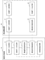
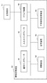
- FIG. 1 shows a configuration example of the remote control device 10 and the delay adjustment device 20 of the present embodiment.
- the remote control device 10 of this embodiment includes a control result receiving unit 11, a control data generating unit 12, a delay setting value determining unit 13, a delay setting value transmitting unit 14, and a control data transmitting unit 15.
- the control result receiving unit 11 is a part that receives a control result from the control target device.
- the control data generation unit 12 is a part that generates control data for performing feedback control with dead time compensation for the control target device based on the control result and the delay set value.
- the delay setting value determination unit 13 is a part that determines a delay setting value based on a history of delay amounts of transmission / reception data transmitted / received to / from the control target device.
- the delay setting value transmission unit 14 is a part that transmits a delay setting value.
- the control data transmission unit 15 is a part that transmits the control data and the generation time of the control data.
- the delay adjustment device 20 of the present embodiment includes a control data receiving unit 21, a control data storage unit 22, a delay set value receiving unit 23, and a control data output unit 24.
- the control data receiving unit 21 is a part that receives control data from the remote control device 10 and stores it in the control data storage unit 22.
- the delay setting value receiving unit 23 is a part that receives a delay setting value used by the dead time compensation control of the remote control device 10.
- the control data output unit 24 is a part that outputs the control data of the control data storage unit to the control target based on the delay setting value and the generation time of the control data.
- the remote control device 10 determines a delay setting value based on the history of the delay amount, transmits the delay setting value to the delay adjustment device 20, and sets the delay setting value. Based on this, control data is generated. Further, the delay adjusting device 20 outputs the control data in the control data storage unit to the control target based on the delay setting value and the generation time of the control data. As a result, the delay set value can be determined according to the history of the delay amount, so that the transient response of the remote control is improved. In addition, since it becomes possible to output control data to a control target in accordance with a delay setting value used for generating control data, the stability of remote control is improved. Therefore, it is possible to improve the transient response and stability of remote control when the transmission delay varies.
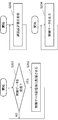
- FIGS. 2 and 3 show examples of operations of the remote control device 10 and the delay adjustment device 20 of the present embodiment.
- FIG. 2 shows an operation example of the remote control device 10 of the present embodiment
- FIG. 3 shows an operation example of the delay adjustment device 20 of the present embodiment.
- the control result receiving unit 11 of the remote control device 10 receives the control result from the control target device (step S101).
- the delay setting value determination unit 13 determines a delay setting value based on the history of the delay amount of transmission / reception data transmitted / received to / from the control target device (step S102).
- the delay setting value transmission unit 14 transmits the delay setting value (step S103).
- the control data generation unit 12 Based on the control result and the delay set value, the control data generation unit 12 generates control data for performing feedback control with dead time compensation for the control target device (step S104).
- the control data transmission unit 15 transmits the control data and the generation time of the control data (step S105).
- control data receiving unit 21 of the delay adjusting device 20 receives the control data from the remote control device 10 (YES in step S201) and stores it in the control data storage unit 22 (step S202).
- the delay setting value receiving unit 23 receives the delay setting value used by the dead time compensation control of the remote control device 10 (step S203).
- the control data output unit 24 outputs the control data in the control data storage unit to the control target based on the delay setting value and the generation time of the control data (step S204).
- the remote control device 10 determines the delay setting value based on the delay amount history, transmits the delay setting value to the delay adjustment device 20, and generates control data based on the delay setting value. Further, the delay adjusting device 20 outputs the control data in the control data storage unit to the control target based on the delay setting value and the generation time of the control data.
- the delay set value can be determined according to the history of the delay amount, so that the transient response of the remote control is improved.
- the stability of remote control is improved. Therefore, it is possible to improve the transient response and stability of remote control when the transmission delay varies.
- the remote control device 10 determines the delay setting value based on the delay amount history, transmits the delay setting value to the delay adjustment device 20, and based on the delay setting value. Control data. Further, the delay adjusting device 20 outputs the control data in the control data storage unit to the control target based on the delay setting value and the generation time of the control data. Therefore, it is possible to improve the transient response and stability of remote control when the transmission delay varies.
- the remote control device and the delay adjustment device of the first embodiment will be described more specifically.
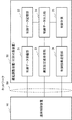
- FIG. 4 shows a configuration example of the remote control system of this embodiment.
- the remote control system according to this embodiment includes the remote control device 10 and the delay adjustment device 30.
- the remote control device 10 is a device that generates control data for a control target and transmits it to the delay adjustment device 30 via the network 80.
- the delay adjustment device 30 is a device that outputs received control data to a control target.
- the delay adjustment device 30 is a control target device.
- the device to be controlled is controlled according to the control data, and the control result (data such as position and speed) is fed back to the remote control device 10.
- the remote control system of the present embodiment may have a configuration in which the control target device 50 and the delay adjustment device 40 are separated as shown in FIG. In the case of FIG. 5, the delay adjustment device 40 includes the control data output unit 44, but the control target device 50 may include the control data output unit 44.
- the network 80 is, for example, an IP network composed of a LAN (Local Area Network), a wireless LAN, the Internet, a mobile network (LTE (Long Term Evolution) / 3G (Generation) / WiMAX (Worldwide Interoperability for Microwave Access)), and the like. It is.
- the control result receiving unit 11 is a part that receives the control result from the control target device (in the case of the present embodiment, the delay adjustment device 30).
- the control data generation unit 12 is a part that generates control data for performing feedback control with dead time compensation for the control target device based on the control result and the delay set value.
- the delay setting value determination unit 13 is a part that determines a delay setting value based on a history of delay amounts of transmission / reception data transmitted / received to / from the control target device.
- the delay setting value transmission unit 14 is a part that transmits a delay setting value.
- the control data transmission unit 15 is a part that transmits the control data and the generation time of the control data.
- FIG. 6 shows a more specific configuration example of the control data generation unit 12.
- the control data generation unit 12 includes a feedback control unit 121 and a dead time compensation unit 122.
- the feedback control unit 121 is a part (compensator) that performs feedback control on the controlled object.
- the feedback control unit 121 generates control data for the control target based on the control target R and the control result fed back from the control target device.
- a PID (Proportional Integral Differential) compensator, a phase lead compensator, a phase delay compensator, or the like can be used.
- Equation 1 the transfer function C (s) of the feedback control unit 121 is expressed by Equation 1.
- KP is a proportional gain
- KI is an integral gain
- the dead time compensation unit 122 is a part (predictor) that compensates for the delay (dead time) in the network 80 with respect to the control data generated by the feedback control unit 121.
- the dead time compensation method for example, Smith prediction, internal model control, model prediction control, or the like can be used.
- the transfer function representing the control object is G (s) and the delay amount (dead time) in the network 80 is L
- the transfer function P (s) of the Smith predictor is Equation 2 can be written.
- the delay amount L is the sum of the forward delay amount and the return delay amount of the network 80 (referred to as round drip time).
- the delay setting value determined by the delay setting value determination unit 13 is used as the delay amount parameter of the dead time compensation unit 122.
- the delay setting value determined by the delay setting value determination unit 13 is used as L in Equation 2.
- the delay setting value determination unit 13 determines the delay setting value based on the history of the delay amount of transmission / reception data transmitted / received to / from the control target device (delay adjustment device 30).
- the delay set value determination unit 13 measures the delay amount in the network 80. Then, for example, an upper limit value L + of the future delay amount is predicted based on the delay amount history. The upper limit value L + is set as a delay setting value.
- an appropriate time series model is identified from a history of past delay amounts, and a method of predicting a probability distribution (probability density function) of future delay amounts from the identified time series model is used.
- a method of predicting a probability distribution (probability density function) of future delay amounts from the identified time series model is used.
- the time series model for example, an AR (Auto-Regressive) model, an MA (Moving-Average) model, an ARIMA (Auto-Regressive-Integrated-Moving-Average) model, a GARCH (Generalized Auto-Regressive-Conditional-Heteroscedasticity) model, and the like can be used.
- the probability distribution (probability density function) f (L, t) of future delay amounts can be calculated. Note that f is a probability density function, L is a delay amount, and t is a time.
- the delay setting value determination unit 13 calculates the upper limit value L + of the future delay amount based on the probability distribution f (L, t) of the future delay amount, for example, using Equation 3.
- ⁇ (t) is the expected value E [L (t)] of the delay amount L at time t
- ⁇ (t) is the standard deviation of the delay amount L at time t
- ⁇ (t) is the square of the delay at time t.
- the delay amount L is the round drip time between the remote control device 10 and the control target device (delay adjustment device 30).
- the delay amount L may be measured by transmitting / receiving probe data for delay amount measurement between the remote control device 10 and the control target device, or receiving control data and control results with time stamps. You may calculate by.
- the delay adjustment apparatus 30 includes a control data receiving unit 21, a control data storage unit 22, a delay set value receiving unit 23, a control data output unit 34, a control target 35, and a control result transmitting unit 36.
- the control data receiving unit 21 is a part that receives control data from the remote control device 10 and stores it in the control data storage unit 22.
- the control data storage unit 22 is a buffer for temporarily storing the control data in order to absorb the arrival delay of the control data.
- the delay setting value receiving unit 23 is a part that receives a delay setting value used by the dead time compensation control of the remote control device 10.
- the control data output unit 34 is a part that outputs the control data of the control data storage unit to the control target 35 based on the delay setting value and the generation time of the control data.
- the control target 35 is a physical model including the drive unit of the control target device, and is a part controlled according to control data.
- the control result transmission unit 36 is a part that transmits a control result (data such as position and speed) to the remote control device 10.
- control data output unit 34 extracts the control data from the control data storage unit 22 after a predetermined time has elapsed from the generation time of the control data, and outputs the control data to the control target 35.
- this predetermined time is called a jitter buffer length.
- the control data output unit 34 uses the delay setting value received by the delay setting value receiving unit 23 as the jitter buffer length.
- each control data is output to the control target when the time corresponding to the delay set value has elapsed from the generation time. Therefore, the arrival delay jitter of each control data is absorbed by the control data storage unit 22.
- the control data storage unit 22 has a role of absorbing delay jitter and keeping the arrival delay of the control data to the control target 35 constant. If the jitter buffer length is longer than the upper limit value of the delay amount, all delay jitter can be absorbed. When the jitter buffer length is shorter than the upper limit value of the delay amount, the arrival delay of the control data to the control target 35 fluctuates, and the control data is transferred to the control target 35 with a delay amount different from the delay amount assumed by the remote control device 10. Control will become unstable. On the other hand, when the jitter buffer length is long, the arrival of the control data to the control target 35 is delayed, and the transient response is deteriorated.
- the upper limit value of the delay amount is calculated as shown in Equation 3 in consideration of the tradeoff between control stability and transient response.
- the remote control device 10 determines a delay setting value based on the history of the delay amount, and transmits the delay setting value to the delay adjustment device 30 to obtain the delay setting value. Based on this, control data is generated. Further, the delay adjusting device 30 outputs the control data in the control data storage unit to the control target based on the delay set value and the generation time of the control data. As a result, the delay set value can be determined according to the history of the delay amount, so that the transient response of the remote control is improved. In addition, since it becomes possible to output control data to a control target in accordance with a delay setting value used for generating control data, the stability of remote control is improved. Therefore, it is possible to improve the transient response and stability of remote control when the transmission delay varies.
- the delay adjustment device 30 outputs the control data to the control target when the time corresponding to the delay set value has elapsed from the generation time of the control data.
- the delay adjusting device 30 can align the delay amount of the control data with the delay setting value, and can further improve the stability of the remote control.
- the remote control device 10 calculates the upper limit value of the future delay amount from the delay amount history, and uses this upper limit value as the delay setting value. As a result, more delay jitter can be absorbed, and the stability of remote control can be further improved.
- the remote control device 10 identifies a predetermined time series model from the delay amount history, derives a probability distribution of the future delay amount from the time series model, and delay amount based on the probability distribution The upper limit value is calculated. This makes it possible to determine the delay setting value in consideration of the trade-off between control stability and transient response.
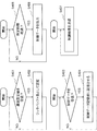
- FIG. 7 shows an operation example of the remote control device 10 of the present embodiment.
- the delay set value determination unit 13 of the remote control device 10 measures the delay amount between the remote control device 10 and the delay adjustment device 30 at a predetermined timing (every predetermined time or the like) (step S301). Then, the delay setting value determining unit 13 determines the delay setting amount at a predetermined timing (step S302), and the delay setting value transmitting unit 14 transmits the determined delay setting amount to the delay adjusting device 30 (step S303). .
- control result receiving unit 11 receives the control result from the delay adjustment device 30 (YES in step S304), and inputs the control result to the control data generating unit 12 (step S305).
- the control data generation unit 12 generates control data based on the control result and the delay setting value at a predetermined timing (step S306). Then, the control data transmission unit 15 transmits the generated control data to the delay adjustment device 30 together with the time when the control data is generated (step S307). For example, a generation time field may be included in a packet including control data.
- FIG. 8 shows an operation example of the delay adjustment device 30 of this embodiment.
- the delay setting value receiving unit 23 of the delay adjusting device 30 sets the delay setting value as the jitter buffer length of the control data storage unit 22 (step S402). ).
- control data receiving unit 21 stores the control data in the control data storage unit 22 (step S404).
- the control data output unit 34 extracts the control data stored in the control data storage unit 22 when the time corresponding to the delay set value has elapsed from the generation time of the control data (step S405), and outputs the control data to the control target 35. (Step S406).
- the control result transmission unit 36 transmits the control result of the control target 35 to the remote control device 10 at a predetermined timing (step S407).
- the remote control device 10 determines the delay setting value based on the delay amount history, transmits it to the delay adjustment device 30, and generates control data based on the delay setting value. Further, the delay adjusting device 30 outputs the control data in the control data storage unit to the control target based on the delay set value and the generation time of the control data.
- the delay set value can be determined according to the history of the delay amount, so that the transient response of the remote control is improved.
- the stability of remote control is improved. Therefore, it is possible to improve the transient response and stability of remote control when the transmission delay varies.
- the remote control device 10 determines the delay setting value based on the history of the delay amount and delay adjustment device 30. Control data is generated based on the delay setting value. Further, the delay adjusting device 30 outputs the control data in the control data storage unit to the control target based on the delay set value and the generation time of the control data. As a result, the delay set value can be determined according to the history of the delay amount, so that the transient response of the remote control is improved. In addition, since it becomes possible to output control data to a control target in accordance with a delay setting value used for generating control data, the stability of remote control is improved. Therefore, it is possible to improve the transient response and stability of remote control when the transmission delay varies.
- the delay adjustment device 30 outputs the control data to the control target when the time corresponding to the delay set value has elapsed from the generation time of the control data.
- the delay adjusting device 30 can align the delay amount of the control data with the delay setting value, and can further improve the stability of the remote control.
- the remote control device 10 calculates the upper limit value of the future delay amount from the delay amount history, and uses this upper limit value as the delay setting value. As a result, more delay jitter can be absorbed, and the stability of remote control can be further improved.
- the remote control device 10 identifies a predetermined time series model from the delay amount history, derives a probability distribution of the future delay amount from the time series model, and delay amount based on the probability distribution The upper limit value is calculated. This makes it possible to determine the delay setting value in consideration of the trade-off between control stability and transient response.
- FIGS. 9 and 10 show examples of simulation results of the second embodiment.
- the control results when the initial value was 0 and the target value was 1 were measured using three patterns of the compensator and the remote control system of the present embodiment.
- the delay amount L was randomly varied between 0.1 msec and 0.8 msec.
- FIG. 9 is an example of a simulation result.
- (A) is a graph showing the control results
- (b) is a graph showing the variation of the delay amount L.
- the control result of a normal PI compensator (Normal PI controller) is not stable until around 5 seconds.
- the PI compensator (Smith compensator) with Smith predictor (fixed delay) has improved control performance compared to the normal PI compensator, but the remote control system (Proposed) of this embodiment further improves the transient characteristics. You can see that it is made.
- Control output and target value RMSE Root Mean Squared Error
- RMSE Root Mean Squared Error
- FIG. 10 is an example of another result under the same simulation conditions as FIG. Also in this result, the RMSE of the control output and the target value is 0.579 for a normal PI compensator, 0.324 for a PI compensator with a Smith predictor (fixed delay), and 0 for the remote control system of this embodiment. .278 and the control performance of the remote control system of this embodiment was the highest.
- the remote control device or the like may be realized using at least two information processing devices physically or functionally. Further, the remote control device or the like may be realized as a dedicated device. In addition, only a part of functions such as a remote control device may be realized using an information processing device.
- FIG. 11 is a diagram schematically illustrating a hardware configuration example of an information processing apparatus capable of realizing the remote control device and the like according to each embodiment of the present invention.
- the information processing device 90 includes a communication interface 91, an input / output interface 92, an arithmetic device 93, a storage device 94, a nonvolatile storage device 95, and a drive device 96.
- the communication interface 91 is a communication means for the remote control device or the like of each embodiment to communicate with an external device in a wired or / and wireless manner. Note that when a remote control device or the like is realized using at least two information processing devices, the devices may be connected to each other via the communication interface 91.
- the input / output interface 92 is a man-machine interface such as a keyboard that is an example of an input device and a display that serves as an output device.
- the arithmetic device 93 is an arithmetic processing device such as a general-purpose CPU (Central Processing Unit) or a microprocessor.
- the arithmetic device 93 can read various programs stored in the nonvolatile storage device 95 into the storage device 94 and execute processing according to the read programs.
- the storage device 94 is a memory device such as a RAM (Random Access Memory) that can be referred to from the arithmetic device 93, and stores programs, various data, and the like.
- the storage device 94 may be a volatile memory device.
- the nonvolatile storage device 95 is a nonvolatile storage device such as a ROM (Read Only Memory) or a flash memory, and can store various programs, data, and the like.
- the drive device 96 is, for example, a device that processes reading and writing of data with respect to a recording medium 97 described later.
- the recording medium 97 is an arbitrary recording medium capable of recording data, such as an optical disk, a magneto-optical disk, and a semiconductor flash memory.
- a remote control device or the like is configured by the information processing device 90 illustrated in FIG. You may implement
- the embodiment can be realized by the arithmetic device 93 executing the program supplied to the remote control device or the like. It is also possible to configure some functions of the information processing apparatus 90 instead of all of the remote control device and the like.
- the program may be recorded in the recording medium 97 so that the program is appropriately stored in the nonvolatile storage device 95 at the shipping stage or the operation stage of the remote control device or the like.
- a method for supplying the program a method of installing the program in a remote control device or the like using an appropriate jig in a manufacturing stage or an operation stage before shipment may be adopted.
- the program supply method may employ a general procedure such as a method of downloading from the outside via a communication line such as the Internet.
- Control result receiving means for receiving a control result from the control target device;
- Control data generating means for generating control data for performing feedback control with dead time compensation for the control target device based on the control result and the delay setting value;
- a delay setting value determining means for determining the delay setting value based on a history of a delay amount of transmission / reception data transmitted / received to / from the control target device;
- a delay amount transmitting means for transmitting the delay setting value;
- Control data transmitting means for transmitting the control data and the generation time of the control data;
- a remote control device comprising:
- the delay setting value determining means identifies a predetermined time series model from the history of the delay amount, derives a probability distribution of the future delay amount from the time series model, and based on the probability distribution, the delay amount.
- Appendix 4 The remote control device according to any one of appendix 1 to appendix 3, wherein a Smith predictor is used for the dead time compensation.
- Control data receiving means for receiving control data from the remote control device and storing it in the control data storage means;
- a delay setting value receiving means for receiving a delay setting value used in dead time compensation of the remote control device;
- Control data output means for outputting the control data of the control data storage means to a control object based on the delay setting value and the generation time of the control data;
- a delay adjusting apparatus comprising:
- Appendix 6 The delay adjustment apparatus according to appendix 5, wherein the control data output means performs the output of the control data to the control target at a time when the delay set value has elapsed from the generation time.
- Appendix 7 The control data transmitting device according to any one of appendix 1 to appendix 4, Comprising the control target device, The remote control system, wherein the device to be controlled is the delay adjusting device according to appendix 5 or appendix 6.
- Appendix 8 The control data transmitting device according to any one of appendix 1 to appendix 4, A delay adjustment device; Comprising the control target device, The remote control system, wherein the delay adjusting device is the delay adjusting device according to appendix 5 or appendix 6.
- Appendix 10 The remote control method according to appendix 9, wherein an upper limit value of the future delay amount is calculated from the history of the delay amount, and the upper limit value is used as the delay setting value.
- a predetermined time series model is identified from the history of the delay amount, a probability distribution of the future delay amount is derived from the time series model, and the upper limit value of the delay amount is calculated based on the probability distribution.
- Appendix 12 The remote control method according to any one of appendix 9 to appendix 11, wherein a Smith predictor is used for the dead time compensation.
- a control result receiving function for receiving a control result from the control target device; Based on the control result and delay setting value, a control data generation function for generating control data for performing feedback control with time delay compensation for the control target device; A delay setting value determining function for determining the delay setting value based on a history of a delay amount of transmission / reception data transmitted / received to / from the control target device; A delay amount transmission function for transmitting the delay setting value; A control data transmission function for transmitting the control data and the generation time of the control data; A remote control program characterized by realizing the above.
- the set value determination function identifies a predetermined time series model from the history of the delay amount, derives a probability distribution of the future delay amount from the time series model, and determines the delay amount based on the probability distribution.
- Appendix 18 The remote control program according to any one of appendix 15 to appendix 17, wherein a Smith predictor is used for the dead time compensation.
- a control data receiving function for receiving control data from a remote control device and storing it in a control data storage unit;
- a delay setting value receiving function for receiving a delay setting value used in dead time compensation of the remote control device;
- a control data output function for outputting the control data of the control data storage unit to a control object based on the delay setting value and the generation time of the control data;
- a delay adjustment program characterized by realizing
- Appendix 20 The delay adjustment program according to appendix 19, wherein the control data output function performs the output of the control data to the control target at a time when the delay set value has elapsed from the generation time.
- Appendix 21 A computer-readable recording medium on which the remote control program according to any one of appendix 15 to appendix 18 is recorded.
- Control result transmission part DESCRIPTION OF SYMBOLS 10 Remote control apparatus 11 Control result receiving part 12 Control data generation part 13 Delay setting value determination part 14 Delay setting value transmission part 15 Control data transmission part 20, 30, 40 Delay adjustment apparatus 21 Control data receiving part 22 Control data storage part 23 Delay setting value receiving unit 24, 34, 44 Control data output unit 35 Control target 36 Control result transmission unit 50 Control target device 80 Network 90 Information processing device 91 Communication interface 92 Input / output interface 93 Arithmetic device 94 Storage device 95 Non-volatile storage device 96 drive device 97 recording medium
Landscapes
- Engineering & Computer Science (AREA)
- Physics & Mathematics (AREA)
- General Physics & Mathematics (AREA)
- Theoretical Computer Science (AREA)
- Signal Processing (AREA)
- Computer Networks & Wireless Communication (AREA)
- Environmental & Geological Engineering (AREA)
- Automation & Control Theory (AREA)
- Mathematical Optimization (AREA)
- Software Systems (AREA)
- Evolutionary Computation (AREA)
- Pure & Applied Mathematics (AREA)
- Computing Systems (AREA)
- General Engineering & Computer Science (AREA)
- Mathematical Physics (AREA)
- Mathematical Analysis (AREA)
- Data Mining & Analysis (AREA)
- Computational Mathematics (AREA)
- Artificial Intelligence (AREA)
- Algebra (AREA)
- Probability & Statistics with Applications (AREA)
- Feedback Control In General (AREA)
Abstract
伝送遅延が変動する場合の遠隔制御の過渡応答および安定性を向上することを可能にするため、遠隔制御装置は、制御対象装置から制御結果を受信し、前記制御結果と遅延設定値に基づいて、前記制御対象装置に対するむだ時間補償付きのフィードバック制御を行う制御データを生成し、前記制御対象装置との間で送受信する送受信データの遅延量の履歴に基づいて前記遅延設定値を決定し、前記遅延設定値を送信し、前記制御データと前記制御データの生成時刻を送信する。また、遅延調整装置は、遠隔制御装置から制御データを受信して制御データ記憶部に記憶させ、前記遠隔制御装置のむだ時間補償で使用する遅延設定値を受信し、前記遅延設定値および前記制御データの生成時刻に基づいて前記制御データ記憶部の前記制御データを制御対象へ出力する。
Description
本発明は、制御対象装置を遠隔で制御する、遠隔制御装置、システム、方法および記録媒体に関する。
UAS(Unmanned Aircraft System)やAGV(Automatic Guided Vehicle)などの機械を制御する際、機械の移動や配置の制約を解消するために、無線通信による遠隔制御が行われる。また、近年では、様々な業務がインターネットを活用しているため、これらの業務を行う機械もインターネットへ接続できることが望まれている。そのため、これらの機械に対する通信もインターネットプロトコル(IP:Internet Protocol)で行われることが増えている。
しかし、無線IP通信では、無線の電波強度、電波干渉、ノイズ、あるいは他の通信トラヒックによって、データパケットの到着遅延およびパケット到着の遅延変動(遅延ジッタ)が発生する。無線IP通信での遠隔制御においては、このパケット到着遅延およびパケット到着の遅延ジッタの影響によって、制御性能(安定性や過渡応答)が損なわれることがある。
特に、制御系においては、遅延そのものよりも、遅延ジッタが大きい場合に高い制御性能を実現することが困難である。通信ネットワークにおいて遅延が発生した場合でも、遅延変動がなく固定的な遅延であれば、スミス予測器などの一般的なむだ時間補償によって制御性能の改善は可能である。
図12は、ある制御対象(一次遅れ系)に対するフィードバック制御の結果(初期値0、制御目標値1)を示したグラフである。(a)は固定的に0.3msecの遅延が存在する場合にPI(Proportional Integral)補償器で制御したときの結果である。遅延(むだ時間)が存在するため、制御出力は目標値である1への収束に時間を要している。一方、(b)は遅延(むだ時間)による影響を考慮し、PI補償器に加えてスミス予測器を備えた場合の制御結果の例である。むだ時間の影響を抑制し、制御性能が大きく改善されていることが分かる。(c)は遅延が0.1msecから0.8msecの間をランダムに変動するような環境において(b)のスミス予測器付きの制御を実施した場合の制御結果である。スミス予測器では遅延が変動する場合には効果が得られないことが分かる。
これは、遅延の変動によって、むだ時間補償で想定していた遅延量とは異なる遅延量で制御対象装置に制御データが到着することが一因である。
遠隔制御の方法としては、たとえば、特許文献1に、むだ時間補償付きのフィードバック制御の方法が記載されている。また、制御対象装置においてパケット到着時間の遅延ジッタを吸収する方法としては、特許文献2に、データ受信側で遅延ジッタ量に基づいて遅延ジッタを吸収するためのジッタバッファ長を決める方法が記載されている。
しかし、特許文献1に記載の方法のようなむだ時間補償方法と特許文献2に記載の方法のような遅延変動の吸収方法を組み合わせても、制御装置が想定している遅延量と、制御対象に入力される制御データの遅延量が異なると、安定した制御を行うことができない。
これに対し、特許文献3に記載の制御装置は、制御対象から通信ネットワークを介して送信された第1データを用いて、通信ネットワークを介して制御対象を制御するための第2データを制御対象へと送信する。そして、制御装置は、制御対象が許容最大遅延時間から第1データを受信した時刻と第1データが生成された時刻の差(第1データの到着遅延時間)を差し引いた時間が経過したタイミングで第2データを送信する。これにより、特許文献3に記載の制御装置は、通信ネットワークにおける遅延をすべて許容最大遅延に統一することで、遅延ジッタがある場合でも、むだ時間補償付きのフィードバック制御の安定性を向上することが可能になる。
また、特許文献4には、むだ時間補償付きのフィードバック制御において、制御装置が複数の想定遅延時間に対応する制御データを送信し、制御対象装置が計測した遅延時間に応じた制御データを選択する方法が記載されている。この方法でも、制御装置の想定遅延量と制御データの遅延量とを合わせることが可能になるため、遅延ジッタがある場合でも、制御の安定性を向上することが可能になる。
しかし、特許文献3に記載の遠隔制御システムでは、通信ネットワークにおける実際の遅延量に関係なく、制御データを固定的に最大許容遅延時間まで遅延させて制御対象へ入力する。そのため、パケット到着遅延および遅延ジッタが小さい環境下においては、無用な遅延を挿入してしまう。制御の過渡応答(追従性)は、遅延が小さいほど良いため、この方法では、過渡応答が劣化してしまう。
また、特許文献4に記載の方法では、遅延変動が大きい環境では、制御装置は多くの想定遅延時間に対する多くの制御データを送信する必要がある。制御データ量が多くなると、ネットワークが混雑して遅延が大きくなり制御の過渡応答を劣化させる可能性がある。また、制御データ量が少ないと、制御装置の想定遅延時間と制御データの遅延量の差が大きくなり、制御の安定性の劣化につながる可能性がある。
本発明の目的は、伝送遅延が変動する場合の遠隔制御の過渡応答および安定性を向上することを可能にする、遠隔制御装置、システム、方法および記録媒体を提供することにある。
上述の問題を解決するために、本発明の遠隔制御装置は、制御対象装置から制御結果を受信する制御結果受信手段と、前記制御結果と遅延設定値に基づいて、前記制御対象装置に対するむだ時間補償付きのフィードバック制御を行う制御データを生成する制御データ生成手段と、前記制御対象装置との間で送受信する送受信データの遅延量の履歴に基づいて前記遅延設定値を決定する遅延設定値決定手段と、前記遅延設定値を送信する遅延量送信手段と、前記制御データと前記制御データの生成時刻を送信する制御データ送信手段と、を備えることを特徴とする。
また、本発明の遅延調整装置は、遠隔制御装置から制御データを受信して制御データ記憶手段に記憶させる制御データ受信手段と、前記遠隔制御装置のむだ時間補償で使用する遅延設定値を受信する遅延設定値受信手段と、前記遅延設定値および前記制御データの生成時刻に基づいて前記制御データ記憶手段の前記制御データを制御対象へ出力する制御データ出力手段と、を備えることを特徴とする。
また、本発明の遠隔制御方法は、制御対象装置から制御結果を受信し、前記制御結果と遅延設定値に基づいて、前記制御対象装置に対するむだ時間補償付きのフィードバック制御を行う制御データを生成し、前記制御対象装置との間で送受信する送受信データの遅延量の履歴に基づいて前記遅延設定値を決定し、前記遅延設定値を送信し、前記制御データと前記制御データの生成時刻を送信することを特徴とする。
また、本発明の遅延調整方法は、遠隔制御装置から制御データを受信して制御データ記憶部に記憶させ、前記遠隔制御装置のむだ時間補償で使用する遅延設定値を受信し、前記遅延設定値および前記制御データの生成時刻に基づいて前記制御データ記憶部の前記制御データを制御対象へ出力することを特徴とする。
また、本発明のコンピュータ読み取り可能な記録媒体に記録された遠隔制御プログラムは、コンピュータに、制御対象装置から制御結果を受信する制御結果受信機能と、前記制御結果と遅延設定値に基づいて、前記制御対象装置に対するむだ時間補償付きのフィードバック制御を行う制御データを生成する制御データ生成機能と、前記制御対象装置との間で送受信する送受信データの遅延量の履歴に基づいて前記遅延設定値を決定する遅延設定値決定機能と、前記遅延設定値を送信する遅延量送信機能と、前記制御データと前記制御データの生成時刻を送信する制御データ送信機能と、を実現させることを特徴とする。
また、本発明のコンピュータ読み取り可能な記録媒体に記録された遅延調整プログラムは、コンピュータに、遠隔制御装置から制御データを受信して制御データ記憶部に記憶させる制御データ受信機能と、前記遠隔制御装置のむだ時間補償で使用する遅延設定値を受信する遅延設定値受信機能と、前記遅延設定値および前記制御データの生成時刻に基づいて前記制御データ記憶部の前記制御データを制御対象へ出力する制御データ出力機能と、を実現させることを特徴とする。
本発明の遠隔制御装置、システム、方法および記録媒体により、伝送遅延が変動する場合の遠隔制御の過渡応答および安定性を向上することが可能になる。
[第一の実施形態]
本発明の第一の実施の形態について説明する。
本発明の第一の実施の形態について説明する。
図1に本実施形態の遠隔制御装置10および遅延調整装置20の構成例を示す。
本実施形態の遠隔制御装置10は、制御結果受信部11、制御データ生成部12、遅延設定値決定部13、遅延設定値送信部14および制御データ送信部15により構成される。
制御結果受信部11は、制御対象装置から制御結果を受信する部分である。制御データ生成部12は、制御結果と遅延設定値に基づいて、制御対象装置に対するむだ時間補償付きのフィードバック制御を行う制御データを生成する部分である。遅延設定値決定部13は、制御対象装置との間で送受信する送受信データの遅延量の履歴に基づいて遅延設定値を決定する部分である。遅延設定値送信部14は、遅延設定値を送信する部分である。制御データ送信部15は、制御データと制御データの生成時刻を送信する部分である。
また、本実施形態の遅延調整装置20は、制御データ受信部21、制御データ記憶部22、遅延設定値受信部23および制御データ出力部24により構成される。
制御データ受信部21は、遠隔制御装置10から制御データを受信して制御データ記憶部22に記憶させる部分である。遅延設定値受信部23は、遠隔制御装置10のむだ時間補償制御が使用する遅延設定値を受信する部分である。制御データ出力部24は、遅延設定値および制御データの生成時刻に基づいて制御データ記憶部の制御データを制御対象へ出力する部分である。
このように遠隔制御装置10および遅延調整装置20を構成することによって、遠隔制御装置10は、遅延量の履歴に基づいて遅延設定値を決定して遅延調整装置20へ送信し、遅延設定値に基づいて制御データを生成する。また、遅延調整装置20は、遅延設定値および制御データの生成時刻に基づいて制御データ記憶部の制御データを制御対象へ出力する。これにより、遅延量の履歴に応じて遅延設定値を決定することが可能になるため、遠隔制御の過渡応答が向上する。また、制御データの生成に使用される遅延設定値に応じて制御対象へ制御データを出力することが可能になるため、遠隔制御の安定性が向上する。そのため、伝送遅延が変動する場合の遠隔制御の過渡応答および安定性を向上することが可能になる。
次に、図2および図3に、本実施形態の遠隔制御装置10および遅延調整装置20の動作の例を示す。図2は本実施形態の遠隔制御装置10の、図3は本実施形態の遅延調整装置20の動作例である。
遠隔制御装置10の制御結果受信部11は、制御対象装置から制御結果を受信する(ステップS101)。遅延設定値決定部13は、制御対象装置との間で送受信する送受信データの遅延量の履歴に基づいて遅延設定値を決定する(ステップS102)。遅延設定値送信部14は、遅延設定値を送信する(ステップS103)。制御データ生成部12は、制御結果と遅延設定値に基づいて、制御対象装置に対するむだ時間補償付きのフィードバック制御を行う制御データを生成する(ステップS104)。制御データ送信部15は、制御データと制御データの生成時刻を送信する(ステップS105)。
また、遅延調整装置20の制御データ受信部21は、遠隔制御装置10から制御データを受信して(ステップS201でYES)、制御データ記憶部22に記憶させる(ステップS202)。遅延設定値受信部23は、遠隔制御装置10のむだ時間補償制御が使用する遅延設定値を受信する(ステップS203)。制御データ出力部24は、遅延設定値および制御データの生成時刻に基づいて制御データ記憶部の制御データを制御対象へ出力する(ステップS204)。
このように動作することによって、遠隔制御装置10は、遅延量の履歴に基づいて遅延設定値を決定して遅延調整装置20へ送信し、遅延設定値に基づいて制御データを生成する。また、遅延調整装置20は、遅延設定値および制御データの生成時刻に基づいて制御データ記憶部の制御データを制御対象へ出力する。これにより、遅延量の履歴に応じて遅延設定値を決定することが可能になるため、遠隔制御の過渡応答が向上する。また、制御データの生成に使用される遅延設定値に応じて制御対象へ制御データを出力することが可能になるため、遠隔制御の安定性が向上する。そのため、伝送遅延が変動する場合の遠隔制御の過渡応答および安定性を向上することが可能になる。
以上で説明したように、本発明の第一の実施形態では、遠隔制御装置10は、遅延量の履歴に基づいて遅延設定値を決定して遅延調整装置20へ送信し、遅延設定値に基づいて制御データを生成する。また、遅延調整装置20は、遅延設定値および制御データの生成時刻に基づいて制御データ記憶部の制御データを制御対象へ出力する。そのため、伝送遅延が変動する場合の遠隔制御の過渡応答および安定性を向上することが可能になる。
[第二の実施形態]
次に、本発明の第二の実施の形態について説明する。
次に、本発明の第二の実施の形態について説明する。
本実施形態では、第一の実施形態の遠隔制御装置および遅延調整装置について、より具体的に説明する。
まず、図4に本実施形態の遠隔制御システムの構成例を示す。本実施形態の遠隔制御システムは、遠隔制御装置10および遅延調整装置30により構成される。
遠隔制御装置10は制御対象に対する制御データを生成してネットワーク80経由で遅延調整装置30へ送信する装置である。遅延調整装置30は、受信した制御データを制御対象へ出力する装置である。本実施形態では、遅延調整装置30は制御対象装置である。制御対象装置は、制御データに従って制御されるとともに、制御結果(位置や速度などのデータ)を遠隔制御装置10へフィードバックする。なお、本実施形態の遠隔制御システムは、図5のように、制御対象装置50と遅延調整装置40とを分離した構成であっても良い。また、図5の場合、遅延調整装置40が制御データ出力部44を備えているが、制御対象装置50が制御データ出力部44を備えていても良い。
ネットワーク80は、たとえば、LAN(Local Area Network)、無線LAN、インターネット、モバイルネットワーク(LTE(Long Term Evolution)/3G(Generation)/WiMAX(Worldwide Interoperability for Microwave Access))などで構成されるIPネットワーク等である。
次に、図1を用いて、本実施形態の遠隔制御装置10の構成例について説明する。
制御結果受信部11は、制御対象装置(本実施形態の場合、遅延調整装置30)から制御結果を受信する部分である。制御データ生成部12は、制御結果と遅延設定値に基づいて、制御対象装置に対するむだ時間補償付きのフィードバック制御を行う制御データを生成する部分である。遅延設定値決定部13は、制御対象装置との間で送受信する送受信データの遅延量の履歴に基づいて遅延設定値を決定する部分である。遅延設定値送信部14は、遅延設定値を送信する部分である。制御データ送信部15は、制御データと制御データの生成時刻を送信する部分である。
次に、図6に制御データ生成部12のより具体的な構成例を示す。制御データ生成部12は、フィードバック制御部121およびむだ時間補償部122を備える。
フィードバック制御部121は、制御対象に対するフィードバック制御を行う部分(補償器)である。フィードバック制御部121は、制御目標Rと制御対象装置からフィードバックされた制御結果に基づいて制御対象に対する制御データを生成する。フィードバック制御部121には、たとえば、PID(Proportional Integral Differential)補償器、位相進み補償器、位相遅れ補償器などを使用できる。
たとえば、フィードバック制御部121としてPI補償器を採用する場合、フィードバック制御部121の伝達関数C(s)は式1のようになる。

なお、KPは比例ゲイン、KIは積分ゲインである。
むだ時間補償部122は、フィードバック制御部121が生成する制御データに対して、ネットワーク80における遅延(むだ時間)を補償する部分(予測器)である。むだ時間補償の方法には、たとえば、スミス予測、内部モデル制御、モデル予測制御等を使用できる。
むだ時間補償部122としてスミス予測器を用いる場合、制御対象を表す伝達関数をG(s)、ネットワーク80における遅延量(むだ時間)をLとすると、スミス予測器の伝達関数P(s)は式2のように書くことができる。

なお、遅延量Lは、ネットワーク80の往路の遅延量と復路の遅延量の合計(ラウンドドリップタイムと呼ぶ)である。
本実施形態では、むだ時間補償部122の遅延量のパラメータに、遅延設定値決定部13で決定した遅延設定値を使用する。たとえば、むだ時間補償部122にスミス予測器を使用する場合、式2のLとして、遅延設定値決定部13で決定した遅延設定値を使用する。
次に、遅延設定値決定部13についてより具体的に説明する。
遅延設定値決定部13は、制御対象装置(遅延調整装置30)との間で送受信する送受信データの遅延量の履歴に基づいて遅延設定値を決定する。
遅延設定値決定部13は、ネットワーク80における遅延量を計測する。そして、たとえば、遅延量の履歴に基づいて、未来の遅延量の上限値L+を予測する。そして、この上限値L+を遅延設定値とする。
予測の方法としては、たとえば、過去の遅延量の履歴から適当な時系列モデルを同定し、同定した時系列モデルから未来の遅延量の確率分布(確率密度関数)を予測する方法を用いることができる。時系列モデルとしては、たとえば、AR(Auto Regressive)モデル、MA(Moving Average)モデル、ARIMA(Auto Regressive Integrated Moving Average)モデル、GARCH(Generalized Auto Regressive Conditional Heteroscedasticity)モデルなどを用いることができる。過去の遅延量の履歴から時系列モデルを同定することができれば、未来の遅延量の確率分布(確率密度関数)f(L、t)を算出することができる。なお、fは確率密度関数、Lは遅延量、tは時刻である。
遅延設定値決定部13は、未来の遅延量の確率分布f(L、t)に基づいて、未来の遅延量の上限値L+を、たとえば、式3で算出する。

なお、μ(t)は時刻tにおける遅延量Lの期待値E[L(t)]、σ(t)は時刻tにおける遅延量Lの標準偏差(σ(t)の二乗は時刻tにおける遅延量Lの分散V[L(t)])、αは定数である。たとえば、確率分布fがガウス分布のとき、α=3とすると、遅延量の上側3シグマの値を上限値とすることになる。
なお、遅延量Lは遠隔制御装置10と制御対象装置(遅延調整装置30)との間のラウンドドリップタイムである。遅延量Lは、遠隔制御装置10と制御対象装置との間で遅延量計測用のプローブデータを送受信することで計測しても良いし、タイムスタンプが付与された制御データや制御結果を受信することで算出しても良い。
次に、図4を用いて、本実施形態の遅延調整装置30の構成例について説明する。本実施形態の遅延調整装置30は、制御データ受信部21、制御データ記憶部22、遅延設定値受信部23、制御データ出力部34、制御対象35および制御結果送信部36により構成される。
制御データ受信部21は、遠隔制御装置10から制御データを受信して制御データ記憶部22に記憶させる部分である。制御データ記憶部22は、制御データの到着遅延を吸収するために、制御データを一時的に保存しておくバッファである。遅延設定値受信部23は、遠隔制御装置10のむだ時間補償制御が使用する遅延設定値を受信する部分である。
制御データ出力部34は、遅延設定値および制御データの生成時刻に基づいて制御データ記憶部の制御データを制御対象35へ出力する部分である。制御対象35は、制御対象装置の駆動部を含めた物理モデルであり、制御データに従って制御される部分である。制御結果送信部36は、制御結果(位置や速度などのデータ)を遠隔制御装置10へ送信する部分である。
本実施形態では、制御データ出力部34は、制御データの生成時刻から所定時間経過後に制御データ記憶部22から当該制御データを取り出し、制御対象35へ出力する。ここでは、この所定時間をジッタバッファ長と呼ぶ。また、本実施形態では、制御データ出力部34は、遅延設定値受信部23が受信した遅延設定値をジッタバッファ長として使用する。
このようにすることで、各制御データは、その生成時間から遅延設定値分の時間が経過したときに制御対象へ出力される。そのため、各制御データの到着遅延のジッタが制御データ記憶部22によって吸収されることになる。
制御データ記憶部22は、遅延のジッタを吸収し、制御データの制御対象35への到着遅延を一定に保つ役割を持つ。ジッタバッファ長が遅延量の上限値より長ければ、すべての遅延ジッタを吸収できる。ジッタバッファ長が遅延量の上限値より短い場合、制御対象35への制御データの到着遅延が変動し、遠隔制御装置10が想定していた遅延量とは異なる遅延量で制御対象35へ制御データが到着するため、制御が不安定になる。一方、ジッタバッファ長が長いと、制御データの制御対象35への到着が遅くなり、過渡応答が劣化する。そのため、本実施形態では、制御の安定性と過渡応答のトレードオフを考慮し、式3のように遅延量の上限値を算出する。これにより、たとえば、3σの値を上限値とすることで、99%の遅延ジッタを吸収し、ジッタバッファ長も長くなり過ぎない値とすることができる。
このように遠隔制御装置10および遅延調整装置30を構成することによって、遠隔制御装置10は、遅延量の履歴に基づいて遅延設定値を決定して遅延調整装置30へ送信し、遅延設定値に基づいて制御データを生成する。また、遅延調整装置30は、遅延設定値および制御データの生成時刻に基づいて制御データ記憶部の制御データを制御対象へ出力する。これにより、遅延量の履歴に応じて遅延設定値を決定することが可能になるため、遠隔制御の過渡応答が向上する。また、制御データの生成に使用される遅延設定値に応じて制御対象へ制御データを出力することが可能になるため、遠隔制御の安定性が向上する。そのため、伝送遅延が変動する場合の遠隔制御の過渡応答および安定性を向上することが可能になる。
また、本実施形態では、遅延調整装置30は、制御データの生成時刻から遅延設定値分の時間が経過したとき、制御データを制御対象へ出力する。これにより、遅延調整装置30は、制御データの遅延量を遅延設定値に揃えることが可能になり、遠隔制御の安定性をより向上することが可能になる。
また、本実施形態では、遠隔制御装置10は、遅延量の履歴から未来の遅延量の上限値を算出し、この上限値を遅延設定値として使用する。これにより、より多くの遅延ジッタを吸収することが可能になり、遠隔制御の安定性をより向上することが可能になる。
また、本実施形態では、遠隔制御装置10は、遅延量の履歴から所定の時系列モデルを同定し、時系列モデルから未来の前記遅延量の確率分布を導出し、確率分布に基づいて遅延量の上限値の算出を行う。これにより、制御の安定性と過渡応答のトレードオフを考慮して遅延設定値を決定することが可能になる。
次に、図7に本実施形態の遠隔制御装置10の動作例を示す。
遠隔制御装置10の遅延設定値決定部13は、遠隔制御装置10と遅延調整装置30との間の遅延量を所定のタイミング(所定時間おき等)で測定する(ステップS301)。そして、遅延設定値決定部13は、所定のタイミングで遅延設定量を決定し(ステップS302)、遅延設定値送信部14は、決定した遅延設定量を遅延調整装置30へ送信する(ステップS303)。
また、制御結果受信部11は、遅延調整装置30から制御結果を受信し(ステップS304でYES)、制御データ生成部12へ制御結果を入力する(ステップS305)。
制御データ生成部12は、所定のタイミングで、制御結果と遅延設定値に基づいて、制御データを生成する(ステップS306)。そして、制御データ送信部15は、生成した制御データを、制御データを生成した時刻とともに遅延調整装置30へ送信する(ステップS307)。たとえば、制御データを含むパケットに生成時刻のフィールドを含めることが考えられる。
次に、図8に本実施形態の遅延調整装置30の動作例を示す。
遅延調整装置30の遅延設定値受信部23は、遠隔制御装置10から遅延設定値を受信すると(ステップS401でYES)、遅延設定値を制御データ記憶部22のジッタバッファ長として設定する(ステップS402)。
また、制御データ受信部21は、遠隔制御装置10から制御データを受信すると(ステップS403でYES)、制御データを制御データ記憶部22に記憶させる(ステップS404)。
制御データ出力部34は、制御データ記憶部22に記憶された制御データを、その制御データの生成時刻から遅延設定値分の時間が経過したときに取り出し(ステップS405)、制御対象35へ出力する(ステップS406)。
制御結果送信部36は、所定のタイミングで制御対象35の制御結果を遠隔制御装置10へ送信する(ステップS407)。
このように動作することによって、遠隔制御装置10は、遅延量の履歴に基づいて遅延設定値を決定して遅延調整装置30へ送信し、遅延設定値に基づいて制御データを生成する。また、遅延調整装置30は、遅延設定値および制御データの生成時刻に基づいて制御データ記憶部の制御データを制御対象へ出力する。これにより、遅延量の履歴に応じて遅延設定値を決定することが可能になるため、遠隔制御の過渡応答が向上する。また、制御データの生成に使用される遅延設定値に応じて制御対象へ制御データを出力することが可能になるため、遠隔制御の安定性が向上する。そのため、伝送遅延が変動する場合の遠隔制御の過渡応答および安定性を向上することが可能になる。
以上で説明したように、本発明の第二の実施形態では、第一の実施形態と同様に、遠隔制御装置10は、遅延量の履歴に基づいて遅延設定値を決定して遅延調整装置30へ送信し、遅延設定値に基づいて制御データを生成する。また、遅延調整装置30は、遅延設定値および制御データの生成時刻に基づいて制御データ記憶部の制御データを制御対象へ出力する。これにより、遅延量の履歴に応じて遅延設定値を決定することが可能になるため、遠隔制御の過渡応答が向上する。また、制御データの生成に使用される遅延設定値に応じて制御対象へ制御データを出力することが可能になるため、遠隔制御の安定性が向上する。そのため、伝送遅延が変動する場合の遠隔制御の過渡応答および安定性を向上することが可能になる。
また、本実施形態では、遅延調整装置30は、制御データの生成時刻から遅延設定値分の時間が経過したとき、制御データを制御対象へ出力する。これにより、遅延調整装置30は、制御データの遅延量を遅延設定値に揃えることが可能になり、遠隔制御の安定性をより向上することが可能になる。
また、本実施形態では、遠隔制御装置10は、遅延量の履歴から未来の遅延量の上限値を算出し、この上限値を遅延設定値として使用する。これにより、より多くの遅延ジッタを吸収することが可能になり、遠隔制御の安定性をより向上することが可能になる。
また、本実施形態では、遠隔制御装置10は、遅延量の履歴から所定の時系列モデルを同定し、時系列モデルから未来の前記遅延量の確率分布を導出し、確率分布に基づいて遅延量の上限値の算出を行う。これにより、制御の安定性と過渡応答のトレードオフを考慮して遅延設定値を決定することが可能になる。
[シミュレーション結果例]
次に、図9および図10に、第二の実施形態のシミュレーション結果の例を示す。
次に、図9および図10に、第二の実施形態のシミュレーション結果の例を示す。
式4の伝達関数G(s)で表される一次遅れ系の制御対象(K=1、T=0.8)に対して、通常のPI補償器、スミス予測器(固定遅延)付きのPI補償器、本実施形態の遠隔制御システムの3パターンで、初期値が0、目標値が1のときの制御結果を計測した。

ただし、遅延量Lは0.1msecから0.8msecの間でランダムに変動させた。
図9は、シミュレーション結果の一例である。(a)は制御結果、(b)が遅延量Lの変動を示したグラフである。通常のPI補償器(Normal PI controller)は、5sec付近まで制御結果が安定していない。スミス予測器(固定遅延)付きのPI補償器(Smith compensator)は通常のPI補償器よりも制御性能は改善しているが、本実施形態の遠隔制御システム(Proposed)では、過渡特性をより改善できていることが分かる。制御出力と目標値のRMSE(Root Mean Squared Error)は、通常のPI補償器で0.731、スミス予測器(固定遅延)付きのPI補償器で0.415、本発明の遠隔制御システムで0.320となる。これにより、本実施形態の遠隔制御システムの制御性能が最も高いことが分かる。
図10は、図9と同じシミュレーション条件での他の結果の例である。本結果においても、制御出力と目標値のRMSEは、通常のPI補償器で0.579、スミス予測器(固定遅延)付きのPI補償器で0.324、本実施形態の遠隔制御システムで0.278となり、本実施形態の遠隔制御システムの制御性能が最も高くなった。
[ハードウェア構成例]
上述した本発明の各実施形態における遠隔制御装置10、遅延調整装置(20、30、40)(以降遠隔制御装置等と呼ぶ)を、一つの情報処理装置(コンピュータ)を用いて実現するハードウェア資源の構成例について説明する。なお、遠隔制御装置等は、物理的または機能的に少なくとも二つの情報処理装置を用いて実現してもよい。また、遠隔制御装置等は、専用の装置として実現してもよい。また、遠隔制御装置等の一部の機能のみを情報処理装置を用いて実現しても良い。
上述した本発明の各実施形態における遠隔制御装置10、遅延調整装置(20、30、40)(以降遠隔制御装置等と呼ぶ)を、一つの情報処理装置(コンピュータ)を用いて実現するハードウェア資源の構成例について説明する。なお、遠隔制御装置等は、物理的または機能的に少なくとも二つの情報処理装置を用いて実現してもよい。また、遠隔制御装置等は、専用の装置として実現してもよい。また、遠隔制御装置等の一部の機能のみを情報処理装置を用いて実現しても良い。
図11は、本発明の各実施形態の遠隔制御装置等を実現可能な情報処理装置のハードウェア構成例を概略的に示す図である。情報処理装置90は、通信インタフェース91、入出力インタフェース92、演算装置93、記憶装置94、不揮発性記憶装置95およびドライブ装置96を備える。
通信インタフェース91は、各実施形態の遠隔制御装置等が、有線あるいは/および無線で外部装置と通信するための通信手段である。なお、遠隔制御装置等を、少なくとも二つの情報処理装置を用いて実現する場合、それらの装置の間を通信インタフェース91経由で相互に通信可能なように接続しても良い。
入出力インタフェース92は、入力デバイスの一例であるキーボードや、出力デバイスとしてのディスプレイ等のマンマシンインタフェースである。
演算装置93は、汎用のCPU(Central Processing Unit)やマイクロプロセッサ等の演算処理装置である。演算装置93は、たとえば、不揮発性記憶装置95に記憶された各種プログラムを記憶装置94に読み出し、読み出したプログラムに従って処理を実行することが可能である。
記憶装置94は、演算装置93から参照可能な、RAM(Random Access Memory)等のメモリ装置であり、プログラムや各種データ等を記憶する。記憶装置94は、揮発性のメモリ装置であっても良い。
不揮発性記憶装置95は、たとえば、ROM(Read Only Memory)、フラッシュメモリ、等の、不揮発性の記憶装置であり、各種プログラムやデータ等を記憶することが可能である。
ドライブ装置96は、たとえば、後述する記録媒体97に対するデータの読み込みや書き込みを処理する装置である。
記録媒体97は、たとえば、光ディスク、光磁気ディスク、半導体フラッシュメモリ等、データを記録可能な任意の記録媒体である。
本発明の各実施形態は、たとえば、図11に例示した情報処理装置90により遠隔制御装置等を構成し、この遠隔制御装置等に対して、上記各実施形態において説明した機能を実現可能なプログラムを供給することにより実現してもよい。
この場合、遠隔制御装置等に対して供給したプログラムを、演算装置93が実行することによって、実施形態を実現することが可能である。また、遠隔制御装置等のすべてではなく、一部の機能を情報処理装置90で構成することも可能である。
さらに、上記プログラムを記録媒体97に記録しておき、遠隔制御装置等の出荷段階、あるいは運用段階等において、適宜上記プログラムが不揮発性記憶装置95に格納されるよう構成してもよい。なお、この場合、上記プログラムの供給方法は、出荷前の製造段階、あるいは運用段階等において、適当な治具を利用して遠隔制御装置等内にインストールする方法を採用してもよい。また、上記プログラムの供給方法は、インターネット等の通信回線を介して外部からダウンロードする方法等の一般的な手順を採用してもよい。
上記の実施形態の一部または全部は、以下の付記のようにも記載されうるが、以下には限られない。
(付記1)
制御対象装置から制御結果を受信する制御結果受信手段と、
前記制御結果と遅延設定値に基づいて、前記制御対象装置に対するむだ時間補償付きのフィードバック制御を行う制御データを生成する制御データ生成手段と、
前記制御対象装置との間で送受信する送受信データの遅延量の履歴に基づいて前記遅延設定値を決定する遅延設定値決定手段と、
前記遅延設定値を送信する遅延量送信手段と、
前記制御データと前記制御データの生成時刻を送信する制御データ送信手段と、
を備えることを特徴とする遠隔制御装置。
制御対象装置から制御結果を受信する制御結果受信手段と、
前記制御結果と遅延設定値に基づいて、前記制御対象装置に対するむだ時間補償付きのフィードバック制御を行う制御データを生成する制御データ生成手段と、
前記制御対象装置との間で送受信する送受信データの遅延量の履歴に基づいて前記遅延設定値を決定する遅延設定値決定手段と、
前記遅延設定値を送信する遅延量送信手段と、
前記制御データと前記制御データの生成時刻を送信する制御データ送信手段と、
を備えることを特徴とする遠隔制御装置。
(付記2)
前記遅延設定値決定手段は、前記遅延量の前記履歴から未来の前記遅延量の上限値を算出し、前記上限値を前記遅延設定値として使用する
ことを特徴とする付記1に記載の遠隔制御装置。
前記遅延設定値決定手段は、前記遅延量の前記履歴から未来の前記遅延量の上限値を算出し、前記上限値を前記遅延設定値として使用する
ことを特徴とする付記1に記載の遠隔制御装置。
(付記3)
前記遅延設定値決定手段は、前記遅延量の前記履歴から所定の時系列モデルを同定し、前記時系列モデルから未来の前記遅延量の確率分布を導出し、前記確率分布に基づいて前記遅延量の前記上限値の前記算出を行う
ことを特徴とする付記2に記載の遠隔制御装置。
前記遅延設定値決定手段は、前記遅延量の前記履歴から所定の時系列モデルを同定し、前記時系列モデルから未来の前記遅延量の確率分布を導出し、前記確率分布に基づいて前記遅延量の前記上限値の前記算出を行う
ことを特徴とする付記2に記載の遠隔制御装置。
(付記4)
前記むだ時間補償にスミス予測器を使用する
ことを特徴とする付記1から付記3のいずれかに記載の遠隔制御装置。
前記むだ時間補償にスミス予測器を使用する
ことを特徴とする付記1から付記3のいずれかに記載の遠隔制御装置。
(付記5)
遠隔制御装置から制御データを受信して制御データ記憶手段に記憶させる制御データ受信手段と、
前記遠隔制御装置のむだ時間補償で使用する遅延設定値を受信する遅延設定値受信手段と、
前記遅延設定値および前記制御データの生成時刻に基づいて前記制御データ記憶手段の前記制御データを制御対象へ出力する制御データ出力手段と、
を備えることを特徴とする遅延調整装置。
遠隔制御装置から制御データを受信して制御データ記憶手段に記憶させる制御データ受信手段と、
前記遠隔制御装置のむだ時間補償で使用する遅延設定値を受信する遅延設定値受信手段と、
前記遅延設定値および前記制御データの生成時刻に基づいて前記制御データ記憶手段の前記制御データを制御対象へ出力する制御データ出力手段と、
を備えることを特徴とする遅延調整装置。
(付記6)
前記制御データ出力手段は、前記生成時刻から前記遅延設定値を経過した時刻に前記制御データの前記制御対象への前記出力を行う
ことを特徴とする付記5に記載の遅延調整装置。
前記制御データ出力手段は、前記生成時刻から前記遅延設定値を経過した時刻に前記制御データの前記制御対象への前記出力を行う
ことを特徴とする付記5に記載の遅延調整装置。
(付記7)
付記1から付記4のいずれかに記載の制御データ送信装置と、
前記制御対象装置と
を備え、
前記制御対象装置は、付記5あるいは付記6に記載の遅延調整装置である
ことを特徴とする遠隔制御システム。
付記1から付記4のいずれかに記載の制御データ送信装置と、
前記制御対象装置と
を備え、
前記制御対象装置は、付記5あるいは付記6に記載の遅延調整装置である
ことを特徴とする遠隔制御システム。
(付記8)
付記1から付記4のいずれかに記載の制御データ送信装置と、
遅延調整装置と、
前記制御対象装置と
を備え、
前記遅延調整装置は、付記5あるいは付記6に記載の遅延調整装置である
ことを特徴とする遠隔制御システム。
付記1から付記4のいずれかに記載の制御データ送信装置と、
遅延調整装置と、
前記制御対象装置と
を備え、
前記遅延調整装置は、付記5あるいは付記6に記載の遅延調整装置である
ことを特徴とする遠隔制御システム。
(付記9)
制御対象装置から制御結果を受信し、
前記制御結果と遅延設定値に基づいて、前記制御対象装置に対するむだ時間補償付きのフィードバック制御を行う制御データを生成し、
前記制御対象装置との間で送受信する送受信データの遅延量の履歴に基づいて前記遅延設定値を決定し、
前記遅延設定値を送信し、
前記制御データと前記制御データの生成時刻を送信する
ことを特徴とする遠隔制御方法。
制御対象装置から制御結果を受信し、
前記制御結果と遅延設定値に基づいて、前記制御対象装置に対するむだ時間補償付きのフィードバック制御を行う制御データを生成し、
前記制御対象装置との間で送受信する送受信データの遅延量の履歴に基づいて前記遅延設定値を決定し、
前記遅延設定値を送信し、
前記制御データと前記制御データの生成時刻を送信する
ことを特徴とする遠隔制御方法。
(付記10)
前記遅延量の前記履歴から未来の前記遅延量の上限値を算出し、前記上限値を前記遅延設定値として使用する
ことを特徴とする付記9に記載の遠隔制御方法。
前記遅延量の前記履歴から未来の前記遅延量の上限値を算出し、前記上限値を前記遅延設定値として使用する
ことを特徴とする付記9に記載の遠隔制御方法。
(付記11)
前記遅延量の前記履歴から所定の時系列モデルを同定し、前記時系列モデルから未来の前記遅延量の確率分布を導出し、前記確率分布に基づいて前記遅延量の前記上限値の前記算出を行う
ことを特徴とする付記10に記載の遠隔制御方法。
前記遅延量の前記履歴から所定の時系列モデルを同定し、前記時系列モデルから未来の前記遅延量の確率分布を導出し、前記確率分布に基づいて前記遅延量の前記上限値の前記算出を行う
ことを特徴とする付記10に記載の遠隔制御方法。
(付記12)
前記むだ時間補償にスミス予測器を使用する
ことを特徴とする付記9から付記11のいずれかに記載の遠隔制御方法。
前記むだ時間補償にスミス予測器を使用する
ことを特徴とする付記9から付記11のいずれかに記載の遠隔制御方法。
(付記13)
遠隔制御装置から制御データを受信して制御データ記憶部に記憶させ、
前記遠隔制御装置のむだ時間補償で使用する遅延設定値を受信し、
前記遅延設定値および前記制御データの生成時刻に基づいて前記制御データ記憶部の前記制御データを制御対象へ出力する
ことを特徴とする遅延調整方法。
遠隔制御装置から制御データを受信して制御データ記憶部に記憶させ、
前記遠隔制御装置のむだ時間補償で使用する遅延設定値を受信し、
前記遅延設定値および前記制御データの生成時刻に基づいて前記制御データ記憶部の前記制御データを制御対象へ出力する
ことを特徴とする遅延調整方法。
(付記14)
前記生成時刻から前記遅延設定値を経過した時刻に前記制御データの前記制御対象への前記出力を行う
ことを特徴とする付記13に記載の遅延調整方法。
前記生成時刻から前記遅延設定値を経過した時刻に前記制御データの前記制御対象への前記出力を行う
ことを特徴とする付記13に記載の遅延調整方法。
(付記15)
コンピュータに、
制御対象装置から制御結果を受信する制御結果受信機能と、
前記制御結果と遅延設定値に基づいて、前記制御対象装置に対するむだ時間補償付きのフィードバック制御を行う制御データを生成する制御データ生成機能と、
前記制御対象装置との間で送受信する送受信データの遅延量の履歴に基づいて前記遅延設定値を決定する遅延設定値決定機能と、
前記遅延設定値を送信する遅延量送信機能と、
前記制御データと前記制御データの生成時刻を送信する制御データ送信機能と、
を実現させることを特徴とする遠隔制御プログラム。
コンピュータに、
制御対象装置から制御結果を受信する制御結果受信機能と、
前記制御結果と遅延設定値に基づいて、前記制御対象装置に対するむだ時間補償付きのフィードバック制御を行う制御データを生成する制御データ生成機能と、
前記制御対象装置との間で送受信する送受信データの遅延量の履歴に基づいて前記遅延設定値を決定する遅延設定値決定機能と、
前記遅延設定値を送信する遅延量送信機能と、
前記制御データと前記制御データの生成時刻を送信する制御データ送信機能と、
を実現させることを特徴とする遠隔制御プログラム。
(付記16)
前記遅延設定値決定機能は、前記遅延量の前記履歴から未来の前記遅延量の上限値を算出し、前記上限値を前記遅延設定値として使用する
ことを特徴とする付記15に記載の遠隔制御プログラム。
前記遅延設定値決定機能は、前記遅延量の前記履歴から未来の前記遅延量の上限値を算出し、前記上限値を前記遅延設定値として使用する
ことを特徴とする付記15に記載の遠隔制御プログラム。
(付記17)
前記設定値決定機能は、前記遅延量の前記履歴から所定の時系列モデルを同定し、前記時系列モデルから未来の前記遅延量の確率分布を導出し、前記確率分布に基づいて前記遅延量の前記上限値の前記算出を行う
ことを特徴とする付記16に記載の遠隔制御プログラム。
前記設定値決定機能は、前記遅延量の前記履歴から所定の時系列モデルを同定し、前記時系列モデルから未来の前記遅延量の確率分布を導出し、前記確率分布に基づいて前記遅延量の前記上限値の前記算出を行う
ことを特徴とする付記16に記載の遠隔制御プログラム。
(付記18)
前記むだ時間補償にスミス予測器を使用する
ことを特徴とする付記15から付記17のいずれかに記載の遠隔制御プログラム。
前記むだ時間補償にスミス予測器を使用する
ことを特徴とする付記15から付記17のいずれかに記載の遠隔制御プログラム。
(付記19)
コンピュータに、
遠隔制御装置から制御データを受信して制御データ記憶部に記憶させる制御データ受信機能と、
前記遠隔制御装置のむだ時間補償で使用する遅延設定値を受信する遅延設定値受信機能と、
前記遅延設定値および前記制御データの生成時刻に基づいて前記制御データ記憶部の前記制御データを制御対象へ出力する制御データ出力機能と、
を実現させることを特徴とする遅延調整プログラム。
コンピュータに、
遠隔制御装置から制御データを受信して制御データ記憶部に記憶させる制御データ受信機能と、
前記遠隔制御装置のむだ時間補償で使用する遅延設定値を受信する遅延設定値受信機能と、
前記遅延設定値および前記制御データの生成時刻に基づいて前記制御データ記憶部の前記制御データを制御対象へ出力する制御データ出力機能と、
を実現させることを特徴とする遅延調整プログラム。
(付記20)
前記制御データ出力機能は、前記生成時刻から前記遅延設定値を経過した時刻に前記制御データの前記制御対象への前記出力を行う
ことを特徴とする付記19に記載の遅延調整プログラム。
前記制御データ出力機能は、前記生成時刻から前記遅延設定値を経過した時刻に前記制御データの前記制御対象への前記出力を行う
ことを特徴とする付記19に記載の遅延調整プログラム。
(付記21)
付記15から付記18のいずれかに記載の遠隔制御プログラムを記録した、コンピュータ読み取り可能な記録媒体。
付記15から付記18のいずれかに記載の遠隔制御プログラムを記録した、コンピュータ読み取り可能な記録媒体。
(付記22)
付記19あるいは付記20のいずれかに記載の遅延調整プログラムを記録した、コンピュータ読み取り可能な記録媒体。
付記19あるいは付記20のいずれかに記載の遅延調整プログラムを記録した、コンピュータ読み取り可能な記録媒体。
以上、上述した実施形態を模範的な例として本発明を説明した。しかしながら、本発明は、上述した実施形態には限定されない。即ち、本発明は、本発明のスコープ内において、当業者が理解し得る様々な態様を適用することができる。
この出願は、2016年8月17日に出願された日本出願特願2016-160139を基礎とする優先権を主張し、その開示の全てをここに取り込む。
10 遠隔制御装置
11 制御結果受信部
12 制御データ生成部
13 遅延設定値決定部
14 遅延設定値送信部
15 制御データ送信部
20、30、40 遅延調整装置
21 制御データ受信部
22 制御データ記憶部
23 遅延設定値受信部
24、34、44 制御データ出力部
35 制御対象
36 制御結果送信部
50 制御対象装置
80 ネットワーク
90 情報処理装置
91 通信インタフェース
92 入出力インタフェース
93 演算装置
94 記憶装置
95 不揮発性記憶装置
96 ドライブ装置
97 記録媒体
11 制御結果受信部
12 制御データ生成部
13 遅延設定値決定部
14 遅延設定値送信部
15 制御データ送信部
20、30、40 遅延調整装置
21 制御データ受信部
22 制御データ記憶部
23 遅延設定値受信部
24、34、44 制御データ出力部
35 制御対象
36 制御結果送信部
50 制御対象装置
80 ネットワーク
90 情報処理装置
91 通信インタフェース
92 入出力インタフェース
93 演算装置
94 記憶装置
95 不揮発性記憶装置
96 ドライブ装置
97 記録媒体
Claims (22)
- 制御対象装置から制御結果を受信する制御結果受信手段と、
前記制御結果と遅延設定値に基づいて、前記制御対象装置に対するむだ時間補償付きのフィードバック制御を行う制御データを生成する制御データ生成手段と、
前記制御対象装置との間で送受信する送受信データの遅延量の履歴に基づいて前記遅延設定値を決定する遅延設定値決定手段と、
前記遅延設定値を送信する遅延量送信手段と、
前記制御データと前記制御データの生成時刻を送信する制御データ送信手段と、
を備えることを特徴とする遠隔制御装置。 - 前記遅延設定値決定手段は、前記遅延量の前記履歴から未来の前記遅延量の上限値を算出し、前記上限値を前記遅延設定値として使用する
ことを特徴とする請求項1に記載の遠隔制御装置。 - 前記遅延設定値決定手段は、前記遅延量の前記履歴から所定の時系列モデルを同定し、前記時系列モデルから未来の前記遅延量の確率分布を導出し、前記確率分布に基づいて前記遅延量の前記上限値の前記算出を行う
ことを特徴とする請求項2に記載の遠隔制御装置。 - 前記むだ時間補償にスミス予測器を使用する
ことを特徴とする請求項1から請求項3のいずれかに記載の遠隔制御装置。 - 遠隔制御装置から制御データを受信して制御データ記憶手段に記憶させる制御データ受信手段と、
前記遠隔制御装置のむだ時間補償で使用する遅延設定値を受信する遅延設定値受信手段と、
前記遅延設定値および前記制御データの生成時刻に基づいて前記制御データ記憶手段の前記制御データを制御対象へ出力する制御データ出力手段と、
を備えることを特徴とする遅延調整装置。 - 前記制御データ出力手段は、前記生成時刻から前記遅延設定値を経過した時刻に前記制御データの前記制御対象への前記出力を行う
ことを特徴とする請求項5に記載の遅延調整装置。 - 請求項1から請求項4のいずれかに記載の制御データ送信装置と、
前記制御対象装置と
を備え、
前記制御対象装置は、請求項5あるいは請求項6に記載の遅延調整装置である
ことを特徴とする遠隔制御システム。 - 請求項1から請求項4のいずれかに記載の制御データ送信装置と、
遅延調整装置と、
前記制御対象装置と
を備え、
前記遅延調整装置は、請求項5あるいは請求項6に記載の遅延調整装置である
ことを特徴とする遠隔制御システム。 - 制御対象装置から制御結果を受信し、
前記制御結果と遅延設定値に基づいて、前記制御対象装置に対するむだ時間補償付きのフィードバック制御を行う制御データを生成し、
前記制御対象装置との間で送受信する送受信データの遅延量の履歴に基づいて前記遅延設定値を決定し、
前記遅延設定値を送信し、
前記制御データと前記制御データの生成時刻を送信する
ことを特徴とする遠隔制御方法。 - 前記遅延量の前記履歴から未来の前記遅延量の上限値を算出し、前記上限値を前記遅延設定値として使用する
ことを特徴とする請求項9に記載の遠隔制御方法。 - 前記遅延量の前記履歴から所定の時系列モデルを同定し、前記時系列モデルから未来の前記遅延量の確率分布を導出し、前記確率分布に基づいて前記遅延量の前記上限値の前記算出を行う
ことを特徴とする請求項10に記載の遠隔制御方法。 - 前記むだ時間補償にスミス予測器を使用する
ことを特徴とする請求項9から請求項11のいずれかに記載の遠隔制御方法。 - 遠隔制御装置から制御データを受信して制御データ記憶部に記憶させ、
前記遠隔制御装置のむだ時間補償で使用する遅延設定値を受信し、
前記遅延設定値および前記制御データの生成時刻に基づいて前記制御データ記憶部の前記制御データを制御対象へ出力する
ことを特徴とする遅延調整方法。 - 前記生成時刻から前記遅延設定値を経過した時刻に前記制御データの前記制御対象への前記出力を行う
ことを特徴とする請求項13に記載の遅延調整方法。 - コンピュータに、
制御対象装置から制御結果を受信する制御結果受信機能と、
前記制御結果と遅延設定値に基づいて、前記制御対象装置に対するむだ時間補償付きのフィードバック制御を行う制御データを生成する制御データ生成機能と、
前記制御対象装置との間で送受信する送受信データの遅延量の履歴に基づいて前記遅延設定値を決定する遅延設定値決定機能と、
前記遅延設定値を送信する遅延量送信機能と、
前記制御データと前記制御データの生成時刻を送信する制御データ送信機能と、
を実現させることを特徴とする遠隔制御プログラム。 - 前記遅延設定値決定機能は、前記遅延量の前記履歴から未来の前記遅延量の上限値を算出し、前記上限値を前記遅延設定値として使用する
ことを特徴とする請求項15に記載の遠隔制御プログラム。 - 前記設定値決定機能は、前記遅延量の前記履歴から所定の時系列モデルを同定し、前記時系列モデルから未来の前記遅延量の確率分布を導出し、前記確率分布に基づいて前記遅延量の前記上限値の前記算出を行う
ことを特徴とする請求項16に記載の遠隔制御プログラム。 - 前記むだ時間補償にスミス予測器を使用する
ことを特徴とする請求項15から請求項17のいずれかに記載の遠隔制御プログラム。 - コンピュータに、
遠隔制御装置から制御データを受信して制御データ記憶部に記憶させる制御データ受信機能と、
前記遠隔制御装置のむだ時間補償で使用する遅延設定値を受信する遅延設定値受信機能と、
前記遅延設定値および前記制御データの生成時刻に基づいて前記制御データ記憶部の前記制御データを制御対象へ出力する制御データ出力機能と、
を実現させることを特徴とする遅延調整プログラム。 - 前記制御データ出力機能は、前記生成時刻から前記遅延設定値を経過した時刻に前記制御データの前記制御対象への前記出力を行う
ことを特徴とする請求項19に記載の遅延調整プログラム。 - 請求項15から請求項18のいずれかに記載の遠隔制御プログラムを記録した、コンピュータ読み取り可能な記録媒体。
- 請求項19あるいは請求項20のいずれかに記載の遅延調整プログラムを記録した、コンピュータ読み取り可能な記録媒体。
Priority Applications (2)
| Application Number | Priority Date | Filing Date | Title |
|---|---|---|---|
| JP2018534355A JP7120014B2 (ja) | 2016-08-17 | 2017-08-07 | 遠隔制御装置、遅延調整装置、遠隔制御システム、遠隔制御方法、遅延調整方法、遠隔制御プログラムおよび遅延調整プログラム |
| US16/325,779 US10965570B2 (en) | 2016-08-17 | 2017-08-07 | Remote control device, system, method, and recording medium for determining a delay setting value |
Applications Claiming Priority (2)
| Application Number | Priority Date | Filing Date | Title |
|---|---|---|---|
| JP2016-160139 | 2016-08-17 | ||
| JP2016160139 | 2016-08-17 |
Publications (1)
| Publication Number | Publication Date |
|---|---|
| WO2018034191A1 true WO2018034191A1 (ja) | 2018-02-22 |
Family
ID=61196622
Family Applications (1)
| Application Number | Title | Priority Date | Filing Date |
|---|---|---|---|
| PCT/JP2017/028647 Ceased WO2018034191A1 (ja) | 2016-08-17 | 2017-08-07 | 遠隔制御装置、システム、方法および記録媒体 |
Country Status (3)
| Country | Link |
|---|---|
| US (1) | US10965570B2 (ja) |
| JP (1) | JP7120014B2 (ja) |
| WO (1) | WO2018034191A1 (ja) |
Cited By (7)
| Publication number | Priority date | Publication date | Assignee | Title |
|---|---|---|---|---|
| JP2021057032A (ja) * | 2019-09-20 | 2021-04-08 | フィッシャー−ローズマウント システムズ,インコーポレイテッド | プロセス近似とラムダ調整を有するプロセスコントローラの設計 |
| WO2022113320A1 (ja) * | 2020-11-30 | 2022-06-02 | 日本電信電話株式会社 | 制御装置、制御方法及び制御プログラム |
| WO2023275944A1 (ja) * | 2021-06-28 | 2023-01-05 | 日本電信電話株式会社 | 遠隔制御システム、方法およびプログラム |
| US11550287B2 (en) | 2019-09-19 | 2023-01-10 | Kabushiki Kaisha Toshiba | Electronic apparatus and method |
| EP4254095A1 (en) | 2022-04-01 | 2023-10-04 | OMRON Corporation | Control system, control device, control method, and control program |
| US11856345B2 (en) | 2018-06-28 | 2023-12-26 | Nec Corporation | Remote control apparatus, remote control method, and program |
| JP2024061421A (ja) * | 2022-10-21 | 2024-05-07 | 日本精工株式会社 | 制御システムおよび制御方法 |
Families Citing this family (4)
| Publication number | Priority date | Publication date | Assignee | Title |
|---|---|---|---|---|
| US11271828B2 (en) | 2018-11-15 | 2022-03-08 | Citrix Systems, Inc. | Real-time scalable virtual session and network analytics |
| US11722422B2 (en) | 2019-05-20 | 2023-08-08 | Citrix Systems, Inc. | Systems and methods for managing streams of packets via intermediary devices |
| JP7214062B2 (ja) * | 2020-12-03 | 2023-01-27 | 三菱電機株式会社 | インタフェース変換装置、制御回路、記憶媒体およびネットワーク構成方法 |
| WO2026006887A1 (en) * | 2024-07-01 | 2026-01-08 | Embraer S.A. | System and method of temporal displacement for improving piloting management of remotely piloted aircrafts |
Citations (2)
| Publication number | Priority date | Publication date | Assignee | Title |
|---|---|---|---|---|
| JPH1165609A (ja) * | 1997-08-20 | 1999-03-09 | Toshiba Corp | 非同期ネットワーク型制御システム,このシステムにおけるプロセス管理方法およびプロセス管理プログラムを記録した記録媒体 |
| JP5565431B2 (ja) * | 2012-04-18 | 2014-08-06 | 横河電機株式会社 | 制御装置及び制御システム |
Family Cites Families (6)
| Publication number | Priority date | Publication date | Assignee | Title |
|---|---|---|---|---|
| US6246610B1 (en) * | 2000-02-22 | 2001-06-12 | Advanced Micro Devices, Inc. | Symmetrical program and erase scheme to improve erase time degradation in NAND devices |
| JP2008078727A (ja) * | 2006-09-19 | 2008-04-03 | Matsushita Electric Ind Co Ltd | 音声伝送システムの遅延設定装置 |
| JP5745204B2 (ja) * | 2008-07-28 | 2015-07-08 | 株式会社バンダイナムコエンターテインメント | プログラム、情報記憶媒体及びゲーム機 |
| JP2014068087A (ja) | 2012-09-25 | 2014-04-17 | Nec Corp | バッファ制御装置、バッファ制御装置による制御方法、メディア通信装置、並びにコンピュータ・プログラム |
| GB201302534D0 (en) | 2013-02-13 | 2013-03-27 | Qatar Foundation | Feedback control as a cloud service |
| JP6134622B2 (ja) * | 2013-09-24 | 2017-05-24 | 株式会社日立製作所 | 通信システム及び時刻同期方法 |
-
2017
- 2017-08-07 US US16/325,779 patent/US10965570B2/en active Active
- 2017-08-07 JP JP2018534355A patent/JP7120014B2/ja active Active
- 2017-08-07 WO PCT/JP2017/028647 patent/WO2018034191A1/ja not_active Ceased
Patent Citations (2)
| Publication number | Priority date | Publication date | Assignee | Title |
|---|---|---|---|---|
| JPH1165609A (ja) * | 1997-08-20 | 1999-03-09 | Toshiba Corp | 非同期ネットワーク型制御システム,このシステムにおけるプロセス管理方法およびプロセス管理プログラムを記録した記録媒体 |
| JP5565431B2 (ja) * | 2012-04-18 | 2014-08-06 | 横河電機株式会社 | 制御装置及び制御システム |
Cited By (10)
| Publication number | Priority date | Publication date | Assignee | Title |
|---|---|---|---|---|
| US11856345B2 (en) | 2018-06-28 | 2023-12-26 | Nec Corporation | Remote control apparatus, remote control method, and program |
| US11550287B2 (en) | 2019-09-19 | 2023-01-10 | Kabushiki Kaisha Toshiba | Electronic apparatus and method |
| JP2021057032A (ja) * | 2019-09-20 | 2021-04-08 | フィッシャー−ローズマウント システムズ,インコーポレイテッド | プロセス近似とラムダ調整を有するプロセスコントローラの設計 |
| JP7499658B2 (ja) | 2019-09-20 | 2024-06-14 | フィッシャー-ローズマウント システムズ,インコーポレイテッド | プロセス近似とラムダ調整を有するプロセスコントローラの設計 |
| WO2022113320A1 (ja) * | 2020-11-30 | 2022-06-02 | 日本電信電話株式会社 | 制御装置、制御方法及び制御プログラム |
| JPWO2022113320A1 (ja) * | 2020-11-30 | 2022-06-02 | ||
| JP7436931B2 (ja) | 2020-11-30 | 2024-02-22 | 日本電信電話株式会社 | 制御装置、制御方法及び制御プログラム |
| WO2023275944A1 (ja) * | 2021-06-28 | 2023-01-05 | 日本電信電話株式会社 | 遠隔制御システム、方法およびプログラム |
| EP4254095A1 (en) | 2022-04-01 | 2023-10-04 | OMRON Corporation | Control system, control device, control method, and control program |
| JP2024061421A (ja) * | 2022-10-21 | 2024-05-07 | 日本精工株式会社 | 制御システムおよび制御方法 |
Also Published As
| Publication number | Publication date |
|---|---|
| JP7120014B2 (ja) | 2022-08-17 |
| US20190215254A1 (en) | 2019-07-11 |
| US10965570B2 (en) | 2021-03-30 |
| JPWO2018034191A1 (ja) | 2019-06-13 |
Similar Documents
| Publication | Publication Date | Title |
|---|---|---|
| JP7120014B2 (ja) | 遠隔制御装置、遅延調整装置、遠隔制御システム、遠隔制御方法、遅延調整方法、遠隔制御プログラムおよび遅延調整プログラム | |
| JP5565431B2 (ja) | 制御装置及び制御システム | |
| US10904162B2 (en) | System and method for selecting optimal path in multi-media multi-path network | |
| US12156118B2 (en) | Methods and apparatus for data traffic routing | |
| JP6698183B2 (ja) | ラウンドトリップタイムスキュー制御の方法および装置 | |
| US11509435B2 (en) | Generating downlink sector beams based on uplink channel estimates utilizing a base band unit pool for modular massive multiple-input multiple-output arrays | |
| JP2016076932A (ja) | プロセス制御システム内でのアナリティクスのためのストリーミングデータ | |
| Wigren | Robust $\mathcal {L} _ {2} $ Stable Networked Control of Wireless Packet Queues in Delayed Internet Connections | |
| CN112673350A (zh) | 用于在具有非受信实体的分布式计算系统中实现动作的协调执行的方法和装置 | |
| JP2016515317A5 (ja) | ||
| WO2018212085A1 (ja) | 送信装置、可用帯域推定装置、可用帯域推定システム、方法および記録媒体 | |
| CN114153174B (zh) | 主从式控制系统的控制方法以及装置、存储介质 | |
| MX2019012072A (es) | Primer nodo de comunicacion, metodo realizado por el mismo, programa de computadora y medio de almacenamiento legible por computadora para manejar paquetes en una red de comunicaciones. | |
| Ikram et al. | Wireless communication in process control loop: Requirements analysis, industry practices and experimental evaluation | |
| US12436527B2 (en) | Technique for performing QoS control in a cloud robotics system | |
| WO2019244828A1 (ja) | パケット転送装置、方法および記録媒体 | |
| WO2016081000A1 (en) | Adjusting a threshold of storage in a buffer according to a latency | |
| CN113225367B (zh) | 主机和客户端之间基于包通信的自动化网络及其运行方法 | |
| Witrant et al. | On the use of state predictors in networked control systems | |
| US20210312792A1 (en) | Control system and control method | |
| WO2017077704A1 (ja) | スループット計測装置、方法および記録媒体 | |
| EP3301843A1 (en) | Method for data processing and receiver device | |
| US9191294B2 (en) | Master device for calculating synchronized actuation time of multiple slave devices and method for controlling the same | |
| WO2019159893A1 (ja) | データ配信装置、システム、方法および記録媒体 | |
| CN113746611B (zh) | 通信中信令的定时值配置方法、计算机装置和存储介质 |
Legal Events
| Date | Code | Title | Description |
|---|---|---|---|
| 121 | Ep: the epo has been informed by wipo that ep was designated in this application |
Ref document number: 17841416 Country of ref document: EP Kind code of ref document: A1 |
|
| ENP | Entry into the national phase |
Ref document number: 2018534355 Country of ref document: JP Kind code of ref document: A |
|
| NENP | Non-entry into the national phase |
Ref country code: DE |
|
| 122 | Ep: pct application non-entry in european phase |
Ref document number: 17841416 Country of ref document: EP Kind code of ref document: A1 |