WO2018034191A1 - Dispositif, système et procédé de commande à distance et support d'enregistrement - Google Patents
Dispositif, système et procédé de commande à distance et support d'enregistrement Download PDFInfo
- Publication number
- WO2018034191A1 WO2018034191A1 PCT/JP2017/028647 JP2017028647W WO2018034191A1 WO 2018034191 A1 WO2018034191 A1 WO 2018034191A1 JP 2017028647 W JP2017028647 W JP 2017028647W WO 2018034191 A1 WO2018034191 A1 WO 2018034191A1
- Authority
- WO
- WIPO (PCT)
- Prior art keywords
- control
- delay
- control data
- setting value
- remote control
- Prior art date
Links
Images


Classifications
-
- H—ELECTRICITY
- H04—ELECTRIC COMMUNICATION TECHNIQUE
- H04L—TRANSMISSION OF DIGITAL INFORMATION, e.g. TELEGRAPHIC COMMUNICATION
- H04L43/00—Arrangements for monitoring or testing data switching networks
- H04L43/08—Monitoring or testing based on specific metrics, e.g. QoS, energy consumption or environmental parameters
- H04L43/0852—Delays
- H04L43/087—Jitter
-
- G—PHYSICS
- G05—CONTROLLING; REGULATING
- G05B—CONTROL OR REGULATING SYSTEMS IN GENERAL; FUNCTIONAL ELEMENTS OF SUCH SYSTEMS; MONITORING OR TESTING ARRANGEMENTS FOR SUCH SYSTEMS OR ELEMENTS
- G05B11/00—Automatic controllers
- G05B11/01—Automatic controllers electric
- G05B11/36—Automatic controllers electric with provision for obtaining particular characteristics, e.g. proportional, integral, differential
-
- G—PHYSICS
- G06—COMPUTING; CALCULATING OR COUNTING
- G06N—COMPUTING ARRANGEMENTS BASED ON SPECIFIC COMPUTATIONAL MODELS
- G06N7/00—Computing arrangements based on specific mathematical models
- G06N7/01—Probabilistic graphical models, e.g. probabilistic networks
Definitions
- the present invention relates to a remote control device, system, method, and recording medium for remotely controlling a control target device.
- IP Internet protocol
- data packet arrival delay and packet arrival delay variation occur due to radio field strength, radio interference, noise, or other communication traffic.
- control performance may be impaired due to the influence of packet arrival delay and packet arrival delay jitter.
- FIG. 12 is a graph showing the result of feedback control (initial value 0, control target value 1) for a certain control target (first-order lag system).
- A is a result when it is controlled by a PI (Proportional Integral) compensator when a fixed delay of 0.3 msec exists. Since there is a delay (dead time), the control output takes time to converge to the target value of 1.
- (b) is an example of a control result when a Smith predictor is provided in addition to the PI compensator in consideration of the influence due to delay (dead time). It can be seen that the control performance is greatly improved by suppressing the influence of the dead time.
- C is a control result when the control with the Smith predictor of (b) is performed in an environment where the delay varies randomly between 0.1 msec and 0.8 msec. It can be seen that the Smith predictor is not effective when the delay varies.
- Patent Document 1 describes a feedback control method with dead time compensation.
- Patent Document 2 describes a method for determining a jitter buffer length for absorbing delay jitter based on the amount of delay jitter on the data receiving side. ing.
- the control device described in Patent Literature 3 uses the first data transmitted from the control target via the communication network, and uses the second data for controlling the control target via the communication network as the control target. Send to. Then, at the timing when the control object subtracts the difference between the time when the first data is received from the allowable maximum delay time and the time when the first data is generated (the arrival delay time of the first data). The second data is transmitted.
- the control device described in Patent Document 3 can improve the stability of feedback control with dead time compensation even when there is delay jitter by unifying all delays in the communication network to the maximum allowable delay. It becomes possible.
- the control device transmits control data corresponding to a plurality of assumed delay times, and selects control data corresponding to the delay times measured by the control target device.
- a method is described. This method also makes it possible to match the assumed delay amount of the control device and the delay amount of the control data, so that the stability of control can be improved even when there is a delay jitter.
- An object of the present invention is to provide a remote control device, a system, a method, and a recording medium that can improve the transient response and stability of remote control when the transmission delay varies.
- the remote control device of the present invention includes a control result receiving unit that receives a control result from the control target device, and a dead time for the control target device based on the control result and the delay setting value.
- Control data generating means for generating control data for performing feedback control with compensation, and delay setting value determining means for determining the delay setting value based on a history of delay amounts of transmission / reception data transmitted / received to / from the control target device
- delay amount transmitting means for transmitting the delay set value
- control data transmitting means for transmitting the control data and the generation time of the control data.
- the delay adjusting device of the present invention receives control data from a remote control device and stores the control data in the control data storage device, and receives a delay setting value used for dead time compensation of the remote control device.
- the remote control method of the present invention receives a control result from a control target device, and generates control data for performing feedback control with dead time compensation on the control target device based on the control result and a delay setting value.
- the delay setting value is determined based on a history of delay amounts of transmission / reception data transmitted / received to / from the control target device, the delay setting value is transmitted, and the generation time of the control data and the control data is transmitted. It is characterized by that.
- the delay adjustment method of the present invention receives control data from a remote control device and stores it in a control data storage unit, receives a delay setting value used for dead time compensation of the remote control device, and receives the delay setting value.
- the control data in the control data storage unit is output to a control target based on the generation time of the control data.
- the remote control program recorded on the computer-readable recording medium of the present invention is based on the control result receiving function for receiving the control result from the control target device, and the control result and the delay setting value.
- the delay setting value is determined based on a control data generation function for generating control data for performing feedback control with dead time compensation for the control target device and a history of delay amounts of transmission / reception data transmitted / received to / from the control target device. And a delay amount transmission function for transmitting the delay setting value, and a control data transmission function for transmitting the control data and the generation time of the control data.
- the delay adjustment program recorded on the computer-readable recording medium of the present invention includes a control data receiving function for causing a computer to receive control data from a remote control device and store the control data in a control data storage unit, and the remote control device A delay setting value receiving function for receiving a delay setting value used in dead time compensation, and a control for outputting the control data in the control data storage unit to a control target based on the delay setting value and the generation time of the control data And a data output function.
- the remote control device, system, method and recording medium of the present invention can improve the transient response and stability of remote control when the transmission delay varies.
- FIG. 1 shows a configuration example of the remote control device 10 and the delay adjustment device 20 of the present embodiment.
- the remote control device 10 of this embodiment includes a control result receiving unit 11, a control data generating unit 12, a delay setting value determining unit 13, a delay setting value transmitting unit 14, and a control data transmitting unit 15.
- the control result receiving unit 11 is a part that receives a control result from the control target device.
- the control data generation unit 12 is a part that generates control data for performing feedback control with dead time compensation for the control target device based on the control result and the delay set value.
- the delay setting value determination unit 13 is a part that determines a delay setting value based on a history of delay amounts of transmission / reception data transmitted / received to / from the control target device.
- the delay setting value transmission unit 14 is a part that transmits a delay setting value.
- the control data transmission unit 15 is a part that transmits the control data and the generation time of the control data.
- the delay adjustment device 20 of the present embodiment includes a control data receiving unit 21, a control data storage unit 22, a delay set value receiving unit 23, and a control data output unit 24.
- the control data receiving unit 21 is a part that receives control data from the remote control device 10 and stores it in the control data storage unit 22.
- the delay setting value receiving unit 23 is a part that receives a delay setting value used by the dead time compensation control of the remote control device 10.
- the control data output unit 24 is a part that outputs the control data of the control data storage unit to the control target based on the delay setting value and the generation time of the control data.
- the remote control device 10 determines a delay setting value based on the history of the delay amount, transmits the delay setting value to the delay adjustment device 20, and sets the delay setting value. Based on this, control data is generated. Further, the delay adjusting device 20 outputs the control data in the control data storage unit to the control target based on the delay setting value and the generation time of the control data. As a result, the delay set value can be determined according to the history of the delay amount, so that the transient response of the remote control is improved. In addition, since it becomes possible to output control data to a control target in accordance with a delay setting value used for generating control data, the stability of remote control is improved. Therefore, it is possible to improve the transient response and stability of remote control when the transmission delay varies.
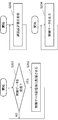
- FIGS. 2 and 3 show examples of operations of the remote control device 10 and the delay adjustment device 20 of the present embodiment.
- FIG. 2 shows an operation example of the remote control device 10 of the present embodiment
- FIG. 3 shows an operation example of the delay adjustment device 20 of the present embodiment.
- the control result receiving unit 11 of the remote control device 10 receives the control result from the control target device (step S101).
- the delay setting value determination unit 13 determines a delay setting value based on the history of the delay amount of transmission / reception data transmitted / received to / from the control target device (step S102).
- the delay setting value transmission unit 14 transmits the delay setting value (step S103).
- the control data generation unit 12 Based on the control result and the delay set value, the control data generation unit 12 generates control data for performing feedback control with dead time compensation for the control target device (step S104).
- the control data transmission unit 15 transmits the control data and the generation time of the control data (step S105).
- control data receiving unit 21 of the delay adjusting device 20 receives the control data from the remote control device 10 (YES in step S201) and stores it in the control data storage unit 22 (step S202).
- the delay setting value receiving unit 23 receives the delay setting value used by the dead time compensation control of the remote control device 10 (step S203).
- the control data output unit 24 outputs the control data in the control data storage unit to the control target based on the delay setting value and the generation time of the control data (step S204).
- the remote control device 10 determines the delay setting value based on the delay amount history, transmits the delay setting value to the delay adjustment device 20, and generates control data based on the delay setting value. Further, the delay adjusting device 20 outputs the control data in the control data storage unit to the control target based on the delay setting value and the generation time of the control data.
- the delay set value can be determined according to the history of the delay amount, so that the transient response of the remote control is improved.
- the stability of remote control is improved. Therefore, it is possible to improve the transient response and stability of remote control when the transmission delay varies.
- the remote control device 10 determines the delay setting value based on the delay amount history, transmits the delay setting value to the delay adjustment device 20, and based on the delay setting value. Control data. Further, the delay adjusting device 20 outputs the control data in the control data storage unit to the control target based on the delay setting value and the generation time of the control data. Therefore, it is possible to improve the transient response and stability of remote control when the transmission delay varies.
- the remote control device and the delay adjustment device of the first embodiment will be described more specifically.
- FIG. 4 shows a configuration example of the remote control system of this embodiment.
- the remote control system according to this embodiment includes the remote control device 10 and the delay adjustment device 30.
- the remote control device 10 is a device that generates control data for a control target and transmits it to the delay adjustment device 30 via the network 80.
- the delay adjustment device 30 is a device that outputs received control data to a control target.
- the delay adjustment device 30 is a control target device.
- the device to be controlled is controlled according to the control data, and the control result (data such as position and speed) is fed back to the remote control device 10.
- the remote control system of the present embodiment may have a configuration in which the control target device 50 and the delay adjustment device 40 are separated as shown in FIG. In the case of FIG. 5, the delay adjustment device 40 includes the control data output unit 44, but the control target device 50 may include the control data output unit 44.
- the network 80 is, for example, an IP network composed of a LAN (Local Area Network), a wireless LAN, the Internet, a mobile network (LTE (Long Term Evolution) / 3G (Generation) / WiMAX (Worldwide Interoperability for Microwave Access)), and the like. It is.
- the control result receiving unit 11 is a part that receives the control result from the control target device (in the case of the present embodiment, the delay adjustment device 30).
- the control data generation unit 12 is a part that generates control data for performing feedback control with dead time compensation for the control target device based on the control result and the delay set value.
- the delay setting value determination unit 13 is a part that determines a delay setting value based on a history of delay amounts of transmission / reception data transmitted / received to / from the control target device.
- the delay setting value transmission unit 14 is a part that transmits a delay setting value.
- the control data transmission unit 15 is a part that transmits the control data and the generation time of the control data.
- FIG. 6 shows a more specific configuration example of the control data generation unit 12.
- the control data generation unit 12 includes a feedback control unit 121 and a dead time compensation unit 122.
- the feedback control unit 121 is a part (compensator) that performs feedback control on the controlled object.
- the feedback control unit 121 generates control data for the control target based on the control target R and the control result fed back from the control target device.
- a PID (Proportional Integral Differential) compensator, a phase lead compensator, a phase delay compensator, or the like can be used.
- Equation 1 the transfer function C (s) of the feedback control unit 121 is expressed by Equation 1.
- KP is a proportional gain
- KI is an integral gain
- the dead time compensation unit 122 is a part (predictor) that compensates for the delay (dead time) in the network 80 with respect to the control data generated by the feedback control unit 121.
- the dead time compensation method for example, Smith prediction, internal model control, model prediction control, or the like can be used.
- the transfer function representing the control object is G (s) and the delay amount (dead time) in the network 80 is L
- the transfer function P (s) of the Smith predictor is Equation 2 can be written.
- the delay amount L is the sum of the forward delay amount and the return delay amount of the network 80 (referred to as round drip time).
- the delay setting value determined by the delay setting value determination unit 13 is used as the delay amount parameter of the dead time compensation unit 122.
- the delay setting value determined by the delay setting value determination unit 13 is used as L in Equation 2.
- the delay setting value determination unit 13 determines the delay setting value based on the history of the delay amount of transmission / reception data transmitted / received to / from the control target device (delay adjustment device 30).
- the delay set value determination unit 13 measures the delay amount in the network 80. Then, for example, an upper limit value L + of the future delay amount is predicted based on the delay amount history. The upper limit value L + is set as a delay setting value.
- an appropriate time series model is identified from a history of past delay amounts, and a method of predicting a probability distribution (probability density function) of future delay amounts from the identified time series model is used.
- a method of predicting a probability distribution (probability density function) of future delay amounts from the identified time series model is used.
- the time series model for example, an AR (Auto-Regressive) model, an MA (Moving-Average) model, an ARIMA (Auto-Regressive-Integrated-Moving-Average) model, a GARCH (Generalized Auto-Regressive-Conditional-Heteroscedasticity) model, and the like can be used.
- the probability distribution (probability density function) f (L, t) of future delay amounts can be calculated. Note that f is a probability density function, L is a delay amount, and t is a time.
- the delay setting value determination unit 13 calculates the upper limit value L + of the future delay amount based on the probability distribution f (L, t) of the future delay amount, for example, using Equation 3.
- ⁇ (t) is the expected value E [L (t)] of the delay amount L at time t
- ⁇ (t) is the standard deviation of the delay amount L at time t
- ⁇ (t) is the square of the delay at time t.
- the delay amount L is the round drip time between the remote control device 10 and the control target device (delay adjustment device 30).
- the delay amount L may be measured by transmitting / receiving probe data for delay amount measurement between the remote control device 10 and the control target device, or receiving control data and control results with time stamps. You may calculate by.
- the delay adjustment apparatus 30 includes a control data receiving unit 21, a control data storage unit 22, a delay set value receiving unit 23, a control data output unit 34, a control target 35, and a control result transmitting unit 36.
- the control data receiving unit 21 is a part that receives control data from the remote control device 10 and stores it in the control data storage unit 22.
- the control data storage unit 22 is a buffer for temporarily storing the control data in order to absorb the arrival delay of the control data.
- the delay setting value receiving unit 23 is a part that receives a delay setting value used by the dead time compensation control of the remote control device 10.
- the control data output unit 34 is a part that outputs the control data of the control data storage unit to the control target 35 based on the delay setting value and the generation time of the control data.
- the control target 35 is a physical model including the drive unit of the control target device, and is a part controlled according to control data.
- the control result transmission unit 36 is a part that transmits a control result (data such as position and speed) to the remote control device 10.
- control data output unit 34 extracts the control data from the control data storage unit 22 after a predetermined time has elapsed from the generation time of the control data, and outputs the control data to the control target 35.
- this predetermined time is called a jitter buffer length.
- the control data output unit 34 uses the delay setting value received by the delay setting value receiving unit 23 as the jitter buffer length.
- each control data is output to the control target when the time corresponding to the delay set value has elapsed from the generation time. Therefore, the arrival delay jitter of each control data is absorbed by the control data storage unit 22.
- the control data storage unit 22 has a role of absorbing delay jitter and keeping the arrival delay of the control data to the control target 35 constant. If the jitter buffer length is longer than the upper limit value of the delay amount, all delay jitter can be absorbed. When the jitter buffer length is shorter than the upper limit value of the delay amount, the arrival delay of the control data to the control target 35 fluctuates, and the control data is transferred to the control target 35 with a delay amount different from the delay amount assumed by the remote control device 10. Control will become unstable. On the other hand, when the jitter buffer length is long, the arrival of the control data to the control target 35 is delayed, and the transient response is deteriorated.
- the upper limit value of the delay amount is calculated as shown in Equation 3 in consideration of the tradeoff between control stability and transient response.
- the remote control device 10 determines a delay setting value based on the history of the delay amount, and transmits the delay setting value to the delay adjustment device 30 to obtain the delay setting value. Based on this, control data is generated. Further, the delay adjusting device 30 outputs the control data in the control data storage unit to the control target based on the delay set value and the generation time of the control data. As a result, the delay set value can be determined according to the history of the delay amount, so that the transient response of the remote control is improved. In addition, since it becomes possible to output control data to a control target in accordance with a delay setting value used for generating control data, the stability of remote control is improved. Therefore, it is possible to improve the transient response and stability of remote control when the transmission delay varies.
- the delay adjustment device 30 outputs the control data to the control target when the time corresponding to the delay set value has elapsed from the generation time of the control data.
- the delay adjusting device 30 can align the delay amount of the control data with the delay setting value, and can further improve the stability of the remote control.
- the remote control device 10 calculates the upper limit value of the future delay amount from the delay amount history, and uses this upper limit value as the delay setting value. As a result, more delay jitter can be absorbed, and the stability of remote control can be further improved.
- the remote control device 10 identifies a predetermined time series model from the delay amount history, derives a probability distribution of the future delay amount from the time series model, and delay amount based on the probability distribution The upper limit value is calculated. This makes it possible to determine the delay setting value in consideration of the trade-off between control stability and transient response.
- FIG. 7 shows an operation example of the remote control device 10 of the present embodiment.
- the delay set value determination unit 13 of the remote control device 10 measures the delay amount between the remote control device 10 and the delay adjustment device 30 at a predetermined timing (every predetermined time or the like) (step S301). Then, the delay setting value determining unit 13 determines the delay setting amount at a predetermined timing (step S302), and the delay setting value transmitting unit 14 transmits the determined delay setting amount to the delay adjusting device 30 (step S303). .
- control result receiving unit 11 receives the control result from the delay adjustment device 30 (YES in step S304), and inputs the control result to the control data generating unit 12 (step S305).
- the control data generation unit 12 generates control data based on the control result and the delay setting value at a predetermined timing (step S306). Then, the control data transmission unit 15 transmits the generated control data to the delay adjustment device 30 together with the time when the control data is generated (step S307). For example, a generation time field may be included in a packet including control data.
- FIG. 8 shows an operation example of the delay adjustment device 30 of this embodiment.
- the delay setting value receiving unit 23 of the delay adjusting device 30 sets the delay setting value as the jitter buffer length of the control data storage unit 22 (step S402). ).
- control data receiving unit 21 stores the control data in the control data storage unit 22 (step S404).
- the control data output unit 34 extracts the control data stored in the control data storage unit 22 when the time corresponding to the delay set value has elapsed from the generation time of the control data (step S405), and outputs the control data to the control target 35. (Step S406).
- the control result transmission unit 36 transmits the control result of the control target 35 to the remote control device 10 at a predetermined timing (step S407).
- the remote control device 10 determines the delay setting value based on the delay amount history, transmits it to the delay adjustment device 30, and generates control data based on the delay setting value. Further, the delay adjusting device 30 outputs the control data in the control data storage unit to the control target based on the delay set value and the generation time of the control data.
- the delay set value can be determined according to the history of the delay amount, so that the transient response of the remote control is improved.
- the stability of remote control is improved. Therefore, it is possible to improve the transient response and stability of remote control when the transmission delay varies.
- the remote control device 10 determines the delay setting value based on the history of the delay amount and delay adjustment device 30. Control data is generated based on the delay setting value. Further, the delay adjusting device 30 outputs the control data in the control data storage unit to the control target based on the delay set value and the generation time of the control data. As a result, the delay set value can be determined according to the history of the delay amount, so that the transient response of the remote control is improved. In addition, since it becomes possible to output control data to a control target in accordance with a delay setting value used for generating control data, the stability of remote control is improved. Therefore, it is possible to improve the transient response and stability of remote control when the transmission delay varies.
- the delay adjustment device 30 outputs the control data to the control target when the time corresponding to the delay set value has elapsed from the generation time of the control data.
- the delay adjusting device 30 can align the delay amount of the control data with the delay setting value, and can further improve the stability of the remote control.
- the remote control device 10 calculates the upper limit value of the future delay amount from the delay amount history, and uses this upper limit value as the delay setting value. As a result, more delay jitter can be absorbed, and the stability of remote control can be further improved.
- the remote control device 10 identifies a predetermined time series model from the delay amount history, derives a probability distribution of the future delay amount from the time series model, and delay amount based on the probability distribution The upper limit value is calculated. This makes it possible to determine the delay setting value in consideration of the trade-off between control stability and transient response.
- FIGS. 9 and 10 show examples of simulation results of the second embodiment.
- the control results when the initial value was 0 and the target value was 1 were measured using three patterns of the compensator and the remote control system of the present embodiment.
- the delay amount L was randomly varied between 0.1 msec and 0.8 msec.
- FIG. 9 is an example of a simulation result.
- (A) is a graph showing the control results
- (b) is a graph showing the variation of the delay amount L.
- the control result of a normal PI compensator (Normal PI controller) is not stable until around 5 seconds.
- the PI compensator (Smith compensator) with Smith predictor (fixed delay) has improved control performance compared to the normal PI compensator, but the remote control system (Proposed) of this embodiment further improves the transient characteristics. You can see that it is made.
- Control output and target value RMSE Root Mean Squared Error
- RMSE Root Mean Squared Error
- FIG. 10 is an example of another result under the same simulation conditions as FIG. Also in this result, the RMSE of the control output and the target value is 0.579 for a normal PI compensator, 0.324 for a PI compensator with a Smith predictor (fixed delay), and 0 for the remote control system of this embodiment. .278 and the control performance of the remote control system of this embodiment was the highest.
- the remote control device or the like may be realized using at least two information processing devices physically or functionally. Further, the remote control device or the like may be realized as a dedicated device. In addition, only a part of functions such as a remote control device may be realized using an information processing device.
- FIG. 11 is a diagram schematically illustrating a hardware configuration example of an information processing apparatus capable of realizing the remote control device and the like according to each embodiment of the present invention.
- the information processing device 90 includes a communication interface 91, an input / output interface 92, an arithmetic device 93, a storage device 94, a nonvolatile storage device 95, and a drive device 96.
- the communication interface 91 is a communication means for the remote control device or the like of each embodiment to communicate with an external device in a wired or / and wireless manner. Note that when a remote control device or the like is realized using at least two information processing devices, the devices may be connected to each other via the communication interface 91.
- the input / output interface 92 is a man-machine interface such as a keyboard that is an example of an input device and a display that serves as an output device.
- the arithmetic device 93 is an arithmetic processing device such as a general-purpose CPU (Central Processing Unit) or a microprocessor.
- the arithmetic device 93 can read various programs stored in the nonvolatile storage device 95 into the storage device 94 and execute processing according to the read programs.
- the storage device 94 is a memory device such as a RAM (Random Access Memory) that can be referred to from the arithmetic device 93, and stores programs, various data, and the like.
- the storage device 94 may be a volatile memory device.
- the nonvolatile storage device 95 is a nonvolatile storage device such as a ROM (Read Only Memory) or a flash memory, and can store various programs, data, and the like.
- the drive device 96 is, for example, a device that processes reading and writing of data with respect to a recording medium 97 described later.
- the recording medium 97 is an arbitrary recording medium capable of recording data, such as an optical disk, a magneto-optical disk, and a semiconductor flash memory.
- a remote control device or the like is configured by the information processing device 90 illustrated in FIG. You may implement
- the embodiment can be realized by the arithmetic device 93 executing the program supplied to the remote control device or the like. It is also possible to configure some functions of the information processing apparatus 90 instead of all of the remote control device and the like.
- the program may be recorded in the recording medium 97 so that the program is appropriately stored in the nonvolatile storage device 95 at the shipping stage or the operation stage of the remote control device or the like.
- a method for supplying the program a method of installing the program in a remote control device or the like using an appropriate jig in a manufacturing stage or an operation stage before shipment may be adopted.
- the program supply method may employ a general procedure such as a method of downloading from the outside via a communication line such as the Internet.
- Control result receiving means for receiving a control result from the control target device;
- Control data generating means for generating control data for performing feedback control with dead time compensation for the control target device based on the control result and the delay setting value;
- a delay setting value determining means for determining the delay setting value based on a history of a delay amount of transmission / reception data transmitted / received to / from the control target device;
- a delay amount transmitting means for transmitting the delay setting value;
- Control data transmitting means for transmitting the control data and the generation time of the control data;
- a remote control device comprising:
- the delay setting value determining means identifies a predetermined time series model from the history of the delay amount, derives a probability distribution of the future delay amount from the time series model, and based on the probability distribution, the delay amount.
- Appendix 4 The remote control device according to any one of appendix 1 to appendix 3, wherein a Smith predictor is used for the dead time compensation.
- Control data receiving means for receiving control data from the remote control device and storing it in the control data storage means;
- a delay setting value receiving means for receiving a delay setting value used in dead time compensation of the remote control device;
- Control data output means for outputting the control data of the control data storage means to a control object based on the delay setting value and the generation time of the control data;
- a delay adjusting apparatus comprising:
- Appendix 6 The delay adjustment apparatus according to appendix 5, wherein the control data output means performs the output of the control data to the control target at a time when the delay set value has elapsed from the generation time.
- Appendix 7 The control data transmitting device according to any one of appendix 1 to appendix 4, Comprising the control target device, The remote control system, wherein the device to be controlled is the delay adjusting device according to appendix 5 or appendix 6.
- Appendix 8 The control data transmitting device according to any one of appendix 1 to appendix 4, A delay adjustment device; Comprising the control target device, The remote control system, wherein the delay adjusting device is the delay adjusting device according to appendix 5 or appendix 6.
- Appendix 10 The remote control method according to appendix 9, wherein an upper limit value of the future delay amount is calculated from the history of the delay amount, and the upper limit value is used as the delay setting value.
- a predetermined time series model is identified from the history of the delay amount, a probability distribution of the future delay amount is derived from the time series model, and the upper limit value of the delay amount is calculated based on the probability distribution.
- Appendix 12 The remote control method according to any one of appendix 9 to appendix 11, wherein a Smith predictor is used for the dead time compensation.
- a control result receiving function for receiving a control result from the control target device; Based on the control result and delay setting value, a control data generation function for generating control data for performing feedback control with time delay compensation for the control target device; A delay setting value determining function for determining the delay setting value based on a history of a delay amount of transmission / reception data transmitted / received to / from the control target device; A delay amount transmission function for transmitting the delay setting value; A control data transmission function for transmitting the control data and the generation time of the control data; A remote control program characterized by realizing the above.
- the set value determination function identifies a predetermined time series model from the history of the delay amount, derives a probability distribution of the future delay amount from the time series model, and determines the delay amount based on the probability distribution.
- Appendix 18 The remote control program according to any one of appendix 15 to appendix 17, wherein a Smith predictor is used for the dead time compensation.
- a control data receiving function for receiving control data from a remote control device and storing it in a control data storage unit;
- a delay setting value receiving function for receiving a delay setting value used in dead time compensation of the remote control device;
- a control data output function for outputting the control data of the control data storage unit to a control object based on the delay setting value and the generation time of the control data;
- a delay adjustment program characterized by realizing
- Appendix 20 The delay adjustment program according to appendix 19, wherein the control data output function performs the output of the control data to the control target at a time when the delay set value has elapsed from the generation time.
- Appendix 21 A computer-readable recording medium on which the remote control program according to any one of appendix 15 to appendix 18 is recorded.
- Control result transmission part DESCRIPTION OF SYMBOLS 10 Remote control apparatus 11 Control result receiving part 12 Control data generation part 13 Delay setting value determination part 14 Delay setting value transmission part 15 Control data transmission part 20, 30, 40 Delay adjustment apparatus 21 Control data receiving part 22 Control data storage part 23 Delay setting value receiving unit 24, 34, 44 Control data output unit 35 Control target 36 Control result transmission unit 50 Control target device 80 Network 90 Information processing device 91 Communication interface 92 Input / output interface 93 Arithmetic device 94 Storage device 95 Non-volatile storage device 96 drive device 97 recording medium
Landscapes
- Engineering & Computer Science (AREA)
- Physics & Mathematics (AREA)
- General Physics & Mathematics (AREA)
- Theoretical Computer Science (AREA)
- Signal Processing (AREA)
- Computer Networks & Wireless Communication (AREA)
- Environmental & Geological Engineering (AREA)
- Automation & Control Theory (AREA)
- Mathematical Optimization (AREA)
- Software Systems (AREA)
- Evolutionary Computation (AREA)
- Pure & Applied Mathematics (AREA)
- Computing Systems (AREA)
- General Engineering & Computer Science (AREA)
- Mathematical Physics (AREA)
- Mathematical Analysis (AREA)
- Data Mining & Analysis (AREA)
- Computational Mathematics (AREA)
- Artificial Intelligence (AREA)
- Algebra (AREA)
- Probability & Statistics with Applications (AREA)
- Feedback Control In General (AREA)
Abstract
Afin de permettre l'amélioration d'une réponse transitoire et la stabilité d'une commande à distance lorsqu'un retard de transmission varie, le dispositif de commande à distance selon l'invention reçoit un résultat de commande d'un dispositif commandé ; génère, sur la base du résultat de commande et d'une valeur de réglage de retard, des données de commande permettant de réaliser une commande de rétroaction par le biais de laquelle le dispositif qui est commandé est compensé pendant un temps perdu ; détermine la valeur de réglage de retard sur la base d'un historique d'une quantité de retard de données d'émission/de réception transmises/reçues au/du dispositif commandé ; transmet la valeur de réglage de retard ; et transmet les données de commande et un temps de génération des données de commande. En outre, un dispositif de réglage de retard reçoit, du dispositif de commande à distance, les données de commande ; stocke, dans une unité de stockage de données de commande, les données de commande ; reçoit la valeur de réglage de retard utilisée pour compenser le temps perdu du dispositif de commande à distance ; et délivre, au dispositif commandé, les données de commande dans l'unité de stockage de données de commande sur la base de la valeur de réglage de retard et du temps de génération des données de commande.
Priority Applications (2)
| Application Number | Priority Date | Filing Date | Title |
|---|---|---|---|
| JP2018534355A JP7120014B2 (ja) | 2016-08-17 | 2017-08-07 | 遠隔制御装置、遅延調整装置、遠隔制御システム、遠隔制御方法、遅延調整方法、遠隔制御プログラムおよび遅延調整プログラム |
| US16/325,779 US10965570B2 (en) | 2016-08-17 | 2017-08-07 | Remote control device, system, method, and recording medium for determining a delay setting value |
Applications Claiming Priority (2)
| Application Number | Priority Date | Filing Date | Title |
|---|---|---|---|
| JP2016160139 | 2016-08-17 | ||
| JP2016-160139 | 2016-08-17 |
Publications (1)
| Publication Number | Publication Date |
|---|---|
| WO2018034191A1 true WO2018034191A1 (fr) | 2018-02-22 |
Family
ID=61196622
Family Applications (1)
| Application Number | Title | Priority Date | Filing Date |
|---|---|---|---|
| PCT/JP2017/028647 WO2018034191A1 (fr) | 2016-08-17 | 2017-08-07 | Dispositif, système et procédé de commande à distance et support d'enregistrement |
Country Status (3)
| Country | Link |
|---|---|
| US (1) | US10965570B2 (fr) |
| JP (1) | JP7120014B2 (fr) |
| WO (1) | WO2018034191A1 (fr) |
Cited By (5)
| Publication number | Priority date | Publication date | Assignee | Title |
|---|---|---|---|---|
| WO2022113320A1 (fr) * | 2020-11-30 | 2022-06-02 | 日本電信電話株式会社 | Dispositif, procédé et programme de commande |
| WO2023275944A1 (fr) * | 2021-06-28 | 2023-01-05 | 日本電信電話株式会社 | Système, procédé et programme de commande à distance |
| US11550287B2 (en) | 2019-09-19 | 2023-01-10 | Kabushiki Kaisha Toshiba | Electronic apparatus and method |
| EP4254095A1 (fr) | 2022-04-01 | 2023-10-04 | OMRON Corporation | Système de commande, dispositif de commande, procédé de commande et programme de commande |
| US11856345B2 (en) | 2018-06-28 | 2023-12-26 | Nec Corporation | Remote control apparatus, remote control method, and program |
Families Citing this family (2)
| Publication number | Priority date | Publication date | Assignee | Title |
|---|---|---|---|---|
| US11582118B2 (en) * | 2018-11-15 | 2023-02-14 | Citrix Systems, Inc. | Real-time scalable virtual session and network analytics |
| US11722422B2 (en) | 2019-05-20 | 2023-08-08 | Citrix Systems, Inc. | Systems and methods for managing streams of packets via intermediary devices |
Citations (2)
| Publication number | Priority date | Publication date | Assignee | Title |
|---|---|---|---|---|
| JPH1165609A (ja) * | 1997-08-20 | 1999-03-09 | Toshiba Corp | 非同期ネットワーク型制御システム,このシステムにおけるプロセス管理方法およびプロセス管理プログラムを記録した記録媒体 |
| JP5565431B2 (ja) * | 2012-04-18 | 2014-08-06 | 横河電機株式会社 | 制御装置及び制御システム |
Family Cites Families (6)
| Publication number | Priority date | Publication date | Assignee | Title |
|---|---|---|---|---|
| US6246610B1 (en) * | 2000-02-22 | 2001-06-12 | Advanced Micro Devices, Inc. | Symmetrical program and erase scheme to improve erase time degradation in NAND devices |
| JP2008078727A (ja) | 2006-09-19 | 2008-04-03 | Matsushita Electric Ind Co Ltd | 音声伝送システムの遅延設定装置 |
| JP5745204B2 (ja) * | 2008-07-28 | 2015-07-08 | 株式会社バンダイナムコエンターテインメント | プログラム、情報記憶媒体及びゲーム機 |
| JP2014068087A (ja) | 2012-09-25 | 2014-04-17 | Nec Corp | バッファ制御装置、バッファ制御装置による制御方法、メディア通信装置、並びにコンピュータ・プログラム |
| GB201302534D0 (en) | 2013-02-13 | 2013-03-27 | Qatar Foundation | Feedback control as a cloud service |
| JP6134622B2 (ja) * | 2013-09-24 | 2017-05-24 | 株式会社日立製作所 | 通信システム及び時刻同期方法 |
-
2017
- 2017-08-07 US US16/325,779 patent/US10965570B2/en active Active
- 2017-08-07 WO PCT/JP2017/028647 patent/WO2018034191A1/fr active Application Filing
- 2017-08-07 JP JP2018534355A patent/JP7120014B2/ja active Active
Patent Citations (2)
| Publication number | Priority date | Publication date | Assignee | Title |
|---|---|---|---|---|
| JPH1165609A (ja) * | 1997-08-20 | 1999-03-09 | Toshiba Corp | 非同期ネットワーク型制御システム,このシステムにおけるプロセス管理方法およびプロセス管理プログラムを記録した記録媒体 |
| JP5565431B2 (ja) * | 2012-04-18 | 2014-08-06 | 横河電機株式会社 | 制御装置及び制御システム |
Cited By (6)
| Publication number | Priority date | Publication date | Assignee | Title |
|---|---|---|---|---|
| US11856345B2 (en) | 2018-06-28 | 2023-12-26 | Nec Corporation | Remote control apparatus, remote control method, and program |
| US11550287B2 (en) | 2019-09-19 | 2023-01-10 | Kabushiki Kaisha Toshiba | Electronic apparatus and method |
| WO2022113320A1 (fr) * | 2020-11-30 | 2022-06-02 | 日本電信電話株式会社 | Dispositif, procédé et programme de commande |
| JP7436931B2 (ja) | 2020-11-30 | 2024-02-22 | 日本電信電話株式会社 | 制御装置、制御方法及び制御プログラム |
| WO2023275944A1 (fr) * | 2021-06-28 | 2023-01-05 | 日本電信電話株式会社 | Système, procédé et programme de commande à distance |
| EP4254095A1 (fr) | 2022-04-01 | 2023-10-04 | OMRON Corporation | Système de commande, dispositif de commande, procédé de commande et programme de commande |
Also Published As
| Publication number | Publication date |
|---|---|
| US20190215254A1 (en) | 2019-07-11 |
| JPWO2018034191A1 (ja) | 2019-06-13 |
| JP7120014B2 (ja) | 2022-08-17 |
| US10965570B2 (en) | 2021-03-30 |
Similar Documents
| Publication | Publication Date | Title |
|---|---|---|
| WO2018034191A1 (fr) | Dispositif, système et procédé de commande à distance et support d'enregistrement | |
| JP5565431B2 (ja) | 制御装置及び制御システム | |
| JP2016530605A5 (fr) | ||
| Chamaken et al. | Joint design of control and communication in wireless networked control systems: A case study | |
| US11509435B2 (en) | Generating downlink sector beams based on uplink channel estimates utilizing a base band unit pool for modular massive multiple-input multiple-output arrays | |
| Xu et al. | A new TCP/AQM system analysis | |
| JP6698183B2 (ja) | ラウンドトリップタイムスキュー制御の方法および装置 | |
| Wigren | Robust $\mathcal {L} _ {2} $ Stable Networked Control of Wireless Packet Queues in Delayed Internet Connections | |
| Scheuvens et al. | Wireless control communications co-design via application-adaptive resource management | |
| US20220386323A1 (en) | Method of processing data related to a transmission of a plurality of data streams | |
| US11005680B2 (en) | Reprogramming apparatus for vehicle, reprogramming method thereof, and vehicle including the same | |
| JP2016515317A5 (fr) | ||
| CN110050488A (zh) | 用于对通信系统中的物理信道执行功率控制的系统和方法 | |
| Ikram et al. | Wireless communication in process control loop: Requirements analysis, industry practices and experimental evaluation | |
| JP7208560B2 (ja) | 制御システム及び制御方法 | |
| WO2019244828A1 (fr) | Dispositif de transfert de paquet, procédé, et support d'enregistrement | |
| WO2017077704A1 (fr) | Dispositif et procédé de mesure de débit de traitement et support d'enregistrement | |
| WO2018212085A1 (fr) | Dispositif de transmission, dispositif d'estimation de bande passante disponible, système et procédé d'estimation de bande passante disponible, et support d'enregistrement | |
| Witrant et al. | On the use of state predictors in networked control systems | |
| CN114153174A (zh) | 主从式控制系统的控制方法以及装置、存储介质 | |
| WO2019159893A1 (fr) | Dispositif, système et procédé de distribution de données et support d'enregistrement | |
| EP3301843A1 (fr) | Procédé destiné à un traitement de données et dispositif récepteur | |
| US9191294B2 (en) | Master device for calculating synchronized actuation time of multiple slave devices and method for controlling the same | |
| CN113225367A (zh) | 主机和客户端之间基于包通信的自动化网络及其运行方法 | |
| WO2018039926A1 (fr) | Procédé d'étalonnage et dispositif de communication |
Legal Events
| Date | Code | Title | Description |
|---|---|---|---|
| 121 | Ep: the epo has been informed by wipo that ep was designated in this application |
Ref document number: 17841416 Country of ref document: EP Kind code of ref document: A1 |
|
| ENP | Entry into the national phase |
Ref document number: 2018534355 Country of ref document: JP Kind code of ref document: A |
|
| NENP | Non-entry into the national phase |
Ref country code: DE |
|
| 122 | Ep: pct application non-entry in european phase |
Ref document number: 17841416 Country of ref document: EP Kind code of ref document: A1 |