WO2018030497A1 - 医療用軟質容器及びそれを用いた栄養供給システム - Google Patents
医療用軟質容器及びそれを用いた栄養供給システム Download PDFInfo
- Publication number
- WO2018030497A1 WO2018030497A1 PCT/JP2017/029015 JP2017029015W WO2018030497A1 WO 2018030497 A1 WO2018030497 A1 WO 2018030497A1 JP 2017029015 W JP2017029015 W JP 2017029015W WO 2018030497 A1 WO2018030497 A1 WO 2018030497A1
- Authority
- WO
- WIPO (PCT)
- Prior art keywords
- container
- sheet
- finger insertion
- medical
- soft
- Prior art date
- Legal status (The legal status is an assumption and is not a legal conclusion. Google has not performed a legal analysis and makes no representation as to the accuracy of the status listed.)
- Ceased
Links
Images









Classifications
-
- A—HUMAN NECESSITIES
- A61—MEDICAL OR VETERINARY SCIENCE; HYGIENE
- A61J—CONTAINERS SPECIALLY ADAPTED FOR MEDICAL OR PHARMACEUTICAL PURPOSES; DEVICES OR METHODS SPECIALLY ADAPTED FOR BRINGING PHARMACEUTICAL PRODUCTS INTO PARTICULAR PHYSICAL OR ADMINISTERING FORMS; DEVICES FOR ADMINISTERING FOOD OR MEDICINES ORALLY; BABY COMFORTERS; DEVICES FOR RECEIVING SPITTLE
- A61J1/00—Containers specially adapted for medical or pharmaceutical purposes
- A61J1/05—Containers specially adapted for medical or pharmaceutical purposes for collecting, storing or administering blood, plasma or medical fluids ; Infusion or perfusion containers
- A61J1/10—Bag-type containers
-
- A—HUMAN NECESSITIES
- A61—MEDICAL OR VETERINARY SCIENCE; HYGIENE
- A61J—CONTAINERS SPECIALLY ADAPTED FOR MEDICAL OR PHARMACEUTICAL PURPOSES; DEVICES OR METHODS SPECIALLY ADAPTED FOR BRINGING PHARMACEUTICAL PRODUCTS INTO PARTICULAR PHYSICAL OR ADMINISTERING FORMS; DEVICES FOR ADMINISTERING FOOD OR MEDICINES ORALLY; BABY COMFORTERS; DEVICES FOR RECEIVING SPITTLE
- A61J1/00—Containers specially adapted for medical or pharmaceutical purposes
- A61J1/14—Details; Accessories therefor
-
- B—PERFORMING OPERATIONS; TRANSPORTING
- B65—CONVEYING; PACKING; STORING; HANDLING THIN OR FILAMENTARY MATERIAL
- B65D—CONTAINERS FOR STORAGE OR TRANSPORT OF ARTICLES OR MATERIALS, e.g. BAGS, BARRELS, BOTTLES, BOXES, CANS, CARTONS, CRATES, DRUMS, JARS, TANKS, HOPPERS, FORWARDING CONTAINERS; ACCESSORIES, CLOSURES, OR FITTINGS THEREFOR; PACKAGING ELEMENTS; PACKAGES
- B65D33/00—Details of, or accessories for, sacks or bags
- B65D33/06—Handles
Definitions
- the present invention relates to a medical soft container and a nutrient supply system using the same.
- Enteral nutrition or parenteral nutrition is known as an example of a method for administering nutrition and drugs to patients without oral administration.
- a liquid such as a nutrient, liquid food, or drug is administered through a tube passed from the patient's nasal cavity to the stomach or duodenum.
- a liquid generally referred to as “infusion”
- nutritional components such as glucose and / or drug components is administered via an infusion circuit inserted into a patient's vein.
- An example of a conventional pouch container is a container in which an opening connected to a filling part is formed between a top sheet and a back sheet on the top of the container, and each sheet is doubled on the top of the top sheet and the back sheet. It has a bag-like portion having a space inside.
- the bag-like portion includes an internal space isolated from the filling portion and an insertion port for inserting a finger into the internal space.
- the insertion opening is, for example, an opening that opens in the width direction, and a semicircular cutout in plan view is provided at one end in the width direction of the top sheet that forms the bag-like portion so that the opening can be easily expanded. Is formed (Patent Document 1).
- Patent Document 1 in the pouch container disclosed in Patent Document 1, since the thumb and index finger are completely inserted into the bag-shaped portion, the filling (liquid material) can be prevented from being applied to the finger, and the opening portion It is described that the container can be stably held while spreading.
- the present invention provides a soft medical container that has good insertability into a finger insertion section, and a nutrient supply system using the soft medical container.
- An example of the medical soft container of the present invention is a medical soft container including a container main body portion including a first surface portion and a second surface portion,
- the container body is A storage section capable of storing a liquid material;
- a finger insertion part that is disposed above the housing part, and each of the first surface part and the upper part of the second surface part includes an internal space that can receive a finger from the width direction;
- the inner surface of each finger insertion part is embossed.
- a medical soft container of the present invention is a medical soft container including a container main body portion including a first surface portion and a second surface portion,
- the container body is A storage section capable of storing a liquid material;
- a finger insertion part that is disposed above the housing part, and each of the first surface part and the upper part of the second surface part includes an internal space that can receive a finger from the width direction;
- a medical soft container of the present invention is a medical soft container including a container main body portion including a first surface portion and a second surface portion,
- the container body is A storage section capable of storing a liquid material;
- a finger insertion part that is disposed above the housing part, and each of the first surface part and the upper part of the second surface part includes an internal space that can receive a finger from the width direction;
- the part facing the outside of the container body part is referred to as an outer sheet
- the part facing the inside of the container body part is referred to as an inner sheet.
- the outer sheet and the inner sheet are composed of one continuous sheet.
- a medical soft container of the present invention is a medical soft container including a container main body portion including a first surface portion and a second surface portion,
- the container body is A storage section capable of storing a liquid material;
- a finger insertion part that is disposed above the housing part, and each of the first surface part and the upper part of the second surface part includes an internal space that can receive a finger from the width direction;
- the part facing the outside of the container body part is referred to as an outer sheet
- the part facing the inside of the container body part is referred to as an inner sheet.
- the bending part bent toward the outer side or inner side of the medical soft container is included.
- a soft medical container including a container main body including a first surface and a second surface,
- the container body is A storage section capable of storing a liquid material;
- a finger insertion part that is disposed above the housing part, and each of the first surface part and the upper part of the second surface part includes an internal space that can receive a finger from the width direction;
- the part facing the outside of the container body part is referred to as an outer sheet, and the part facing the inside of the container body part is referred to as an inner sheet.
- the upper edge portion and the lower edge portion of each finger insertion portion each include an upper edge joint portion and a lower edge joint portion in which the outer sheet and the inner sheet are joined, The lengths of the outer sheet and the inner sheet in the vertical direction are different from each other.
- the nutrient supply system of the present invention includes the soft medical container of the present invention.
- the present invention it is possible to provide a soft medical container that has good insertability into the finger insertion portion, and a nutrient supply system including the soft medical container.
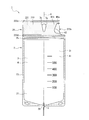
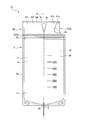
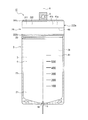
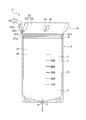
- FIG. 1 is a front view of an example of the medical soft container of the present invention.
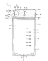
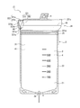
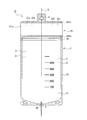
- FIG. 2 is a rear view of the soft medical container shown in FIG.
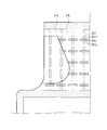
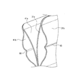
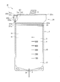
- FIG. 3 is a view showing a state where the inner sheet and the outer sheet of the finger insertion portion of the soft medical container shown in FIG. 1 are separated.
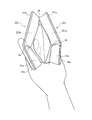
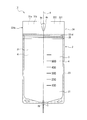
- FIG. 4 is a diagram illustrating a state where the opening of the soft medical container shown in FIG. 1 is opened.
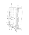
- FIG. 5 is a partially enlarged view of the soft medical container shown in FIG.
- FIG. 6 is a partially enlarged view of the soft medical container shown in FIG.
- FIG. 7 is a partially enlarged view of the soft medical container shown in FIG.
- FIG. 8 is a front view of another example of the medical soft container of the present invention.
- FIG. 1 is a front view of an example of the medical soft container of the present invention.
- FIG. 2 is a rear view of the soft medical container shown in FIG.
- FIG. 3 is a view showing a state where the inner
- FIG. 9 is a rear view of the soft medical container shown in FIG.
- FIG. 10 is a diagram illustrating a state where the inner sheet and the outer sheet of the finger insertion portion of the soft medical container illustrated in FIG. 8 are separated from each other.
- FIG. 11 is a front view of another example of the medical soft container of the present invention.
- FIG. 12 is a rear view of another example of the medical soft container of the present invention.
- FIG. 13 is a view showing a state where the inner sheet and the outer sheet of the finger insertion portion of the soft medical container shown in FIG. 11 are separated.
- FIG. 14 is a front view of another example of the medical soft container of the present invention.
- FIG. 15 is a rear view of another example of the medical soft container of the present invention.
- FIG. 16 is a diagram illustrating a state where the inner sheet and the outer sheet of the finger insertion portion of the soft medical container illustrated in FIG. 14 are separated from each other.
- FIG. 17 is a partially enlarged view of the soft medical container shown in FIG.
- FIG. 18 is a diagram for explaining another example of a bent portion.
- FIG. 19 is a front view of another example of the medical soft container of the present invention.
- FIG. 20 is a rear view of another example of the medical soft container of the present invention.
- FIG. 21 is a diagram illustrating a state where the inner sheet and the outer sheet of the finger insertion portion of the soft medical container illustrated in FIG. 19 are separated from each other.
- FIG. 22 is a front view of another example of the medical soft container of the present invention.
- FIG. 23 is a rear view of another example of the medical soft container of the present invention.
- 24 is a view showing a state where the inner sheet and the outer sheet of the finger insertion part of the soft medical container shown in FIG. 22 are separated from each other.
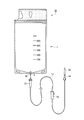
- FIG. 25 is a front view of an example of the nutrient supply system of the present invention.
- the present invention further discloses the following [1] to [28].
- a medical soft container including a container main body including a first surface portion and a second surface portion, The container body is A storage section capable of storing a liquid material; A finger insertion part that is disposed above the housing part, and each of the first surface part and the upper part of the second surface part includes an internal space that can receive a finger from the width direction; A soft medical container that is embossed at least at the insertion start side end of the finger and in the vicinity thereof on the inner surface of each finger insertion portion. [2] The soft medical container according to [1], wherein embossing is performed on at least a finger insertion start side of the inner surface of each finger insertion portion.
- each finger insertion portion a portion facing the outside of the container main body is referred to as an outer sheet, and a portion facing the inside of the container main body is referred to as an inner sheet.
- embossing is applied to at least one of the surfaces of the outer sheet and the inner sheet facing each other.
- Embossing is performed on both of the opposite surfaces of the outer sheet and the inner sheet, The top surface of the first convex portion formed by embossing on the outer sheet and the top surface of the second convex portion formed by embossing on the inner sheet are in contact with each other.
- the first convex portion and the second convex portion are linear convex portions, The medical soft container according to [4], wherein the longitudinal direction of the first convex portion and the longitudinal direction of the second convex portion are different from each other.
- a soft medical container including a container main body including a first surface portion and a second surface portion, The container body is A storage section capable of storing a liquid material; A finger insertion part that is disposed above the housing part, and each of the first surface part and the upper part of the second surface part includes an internal space that can receive a finger from the width direction; A soft medical container in which a fold fold is formed in a direction away from the insertion start side end at least on the finger insertion start side of each finger insertion portion.
- each finger insertion portion the portion facing the outside of the container body portion is referred to as an outer sheet, and the portion facing the inside is referred to as an inner sheet.
- a soft medical container including a container main body including a first surface and a second surface,
- the container body is A storage section capable of storing a liquid material;
- a finger insertion part that is disposed above the housing part, and each of the first surface part and the upper part of the second surface part includes an internal space that can receive a finger from the width direction;
- the part facing the outside of the container body part is referred to as an outer sheet, and the part facing the inside of the container body part is referred to as an inner sheet.
- seat consist of one continuous sheet
- a soft medical container including a container main body including a first surface and a second surface,
- the container body is A storage section capable of storing a liquid material;
- a finger insertion part that is disposed above the housing part, and each of the first surface part and the upper part of the second surface part includes an internal space that can receive a finger from the width direction;
- the part facing the outside of the container body part is referred to as an outer sheet, and the part facing the inside of the container body part is referred to as an inner sheet.
- a medical soft container including a bent portion bent toward the outer side or the inner side of the medical soft container with respect to at least one of the outer sheet and the inner sheet.
- a medical soft container including a container main body including a first surface portion and a second surface portion,
- the container body is A storage section capable of storing a liquid material;
- a finger insertion part that is disposed above the housing part, and each of the first surface part and the upper part of the second surface part includes an internal space that can receive a finger from the width direction;
- the part facing the outside of the container body part is referred to as an outer sheet, and the part facing the inside of the container body part is referred to as an inner sheet.
- each finger insertion portion each include an upper edge joint portion and a lower edge joint portion in which the outer sheet and the inner sheet are joined,
- a soft medical container wherein the outer sheet and the inner sheet have different vertical lengths.
- the side of the finger insertion portion close to the finger insertion start side is bent so that the width of the pair of finger insertion portions is the width of the accommodating portion.
- the medical soft container according to any one of [1] to [14], which is narrower.
- a notch portion is formed in one of the outer sheet and the inner sheet on the finger insertion start side of the finger insertion section.
- each finger insertion part each include an upper edge joint and a lower edge joint where the outer sheet and the inner sheet are joined, The notch portion is inserted between the upper edge joint portion and the lower edge joint portion so that a part of the outer sheet remains between the finger insertion start side of the finger insertion portion.
- the soft medical container according to [16] which is formed at an end of the medical device.
- the side constituting the outline of the notch is substantially U-shaped, The side of the U-shaped bottom portion is inclined in a direction in which the distance from the insertion start side end gradually increases along the direction toward the bottom side of the medical soft container.
- a hole is formed in at least one of the inner sheet and the outer sheet, a thumb of one hand is inserted into one finger insertion portion, and a finger other than the thumb of the one hand is inserted into the other finger insertion portion.
- the pair of finger insertion parts bends in a dogleg shape with the hole as a trough.
- FIG. 1 is a front view of an example of the medical soft container of the present invention
- FIG. 2 is a rear view of the medical soft container 1 shown in FIG. 1, and FIG. It is the figure which showed the state which released
- FIG. 4 is a diagram illustrating a state in which the opening of the medical soft container 1 is opened
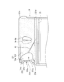
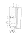
- FIGS. 5 to 7 are partially enlarged views of the medical soft container 1.
- the vertical direction of the sheet of FIG. 1 is referred to as the “vertical direction” of the medical soft container, and the direction orthogonal to the “vertical direction” is referred to as the “width direction”.
- the “vertical direction” is equal to the longitudinal direction of the central axis of the medical soft container.
- the medical soft container 1 shown in FIGS. 1 to 7 includes a container body 2 and a discharge port 5 fixed to the discharge port 26 of the container body 2.
- the container main body 2 includes a storage portion 21 for storing a liquid substance, and a pair of finger insertion portions 221 and 222 (hereinafter referred to as “finger insertion portion 221”) disposed above the storage portion 21.
- finger insertion portion 221 and the finger insertion portion 222 "are also referred to as” second finger insertion portion 222 ").
- the container main body 2 includes a peripheral joint 23 formed by heat bonding (heat sealing) or the like on the three sides of the outer peripheral edges of the first surface 3 and the second surface 4. Between the first surface portion 3 and the second surface portion 4 in the upper part of the container main body portion 2, an opening 24 connected to the accommodating portion 21 is provided. When the container 21 is filled with the liquid material, the opening 24 is positioned above the container 21. On the first surface portion 3 and the second surface portion 4, scales for confirming the amount of liquid material injected into the accommodating portion 21 are displayed.
- a zip 25 (engagement portion that can be opened and closed again) that allows the storage portion 21 to be opened and closed with respect to the outside of the storage portion 21.
- the zip 25 can be formed by a conventionally known method.
- the first surface portion 3 has a relatively large area of the first sheet 31 and a smaller area than the first sheet 31, and heat is applied to the inner surface above the zip 25 of the first sheet 31.
- a first inner sheet 31a joined by bonding or the like.
- the first inner sheet 31a has at least an upper edge portion and a lower edge portion so as to form at least one opening opened in the width direction in order to allow insertion of a finger from the width direction. It is joined to the sheet 31.
- seat 31b the 1st surface part 3 will be arrange
- seat will be described.
- seat 31b The 1st finger insertion part 221 which enables a finger to insert between the 1st inner sheet
- the upper edge portion and the lower edge portion of the first finger insertion portion 221 are respectively a first upper edge joint portion 221c in which a first outer sheet 31b and a first inner sheet 31a are joined. And a first lower edge joint portion 221d.
- the second surface portion 4 includes a second sheet 41 having a relatively large area and an inner surface that is smaller in area than the second sheet 41 and is above the zip 25 of the second sheet 41.
- seat 41a joined to.
- the second inner sheet 41a has at least an upper edge portion and a lower edge portion so as to form at least one opening opened in the width direction in order to allow insertion of a finger from the width direction. It is joined to the sheet 41.
- seat 41b the 2nd surface part 4 will be arrange
- seat 41b The 2nd finger insertion part 222 which can insert a finger between the 2nd inner sheet
- the upper edge portion and the lower edge portion of the second finger insertion portion 222 are respectively the second upper edge joint portion 222c in which the second outer sheet 41b and the second inner sheet 41a are joined. And a second lower edge joint portion 222d.
- first inner sheet and second inner sheet are both abbreviated as “inner sheet”, and “first outer sheet” and “second outer sheet” are both abbreviated as “outer sheet”.
- first upper edge joint and the “second upper edge joint” are abbreviated as “upper edge joint”, and the “first lower edge joint” and the “second lower edge joint” are both referred to.
- first lower edge joint and the “second lower edge joint” are both referred to.
- the inner surface of the first outer sheet 31 b (the surface facing the first inner sheet 31 a) is embossed so that the first convex portion protrudes toward the first inner sheet 31 a. 32e is formed.
- a second convex portion 32f protruding toward the first outer sheet 31b is formed by embossing. .
- the first convex portion 32e is a linear convex portion whose longitudinal direction coincides with the width direction of the medical soft container 1, and a plurality of first convex portions 32e are formed in the width direction on the inner surface of the first outer sheet 31b. It is formed at equal intervals along.
- the second convex portion 32f is a linear convex portion whose longitudinal direction coincides with the vertical direction of the medical soft container 1, and a plurality of second convex portions 32f are formed on the inner surface of the first inner sheet 31a. It is formed at equal intervals along the direction.
- FIG. 7 shows, for example, the longitudinal direction of the 1st convex part 32e and the longitudinal direction of the 2nd convex part 32f are orthogonal, and the top surface 321e of the 1st convex part 32e and the 2nd convex part
- the first outer sheet 31b and the first inner sheet 31a are superposed in a positional relationship where the top surface 321f of 32f abuts. For this reason, the first outer sheet 31b and the first inner sheet 31a are prevented from being in close contact with each other during the bag making process, and there is a slight gap between the two.
- the insertability of a finger into 221 is improved.
- the first protrusion 32e and the second protrusion 32f are easily aligned because each protrusion is linear, one is oriented in the width direction and the other is oriented in the vertical direction. Can be done.
- a linear first convex portion is formed on the surface of the second outer sheet 41b facing the second inner sheet 41a, and the surface of the second inner sheet 41a facing the second outer sheet 41b is also linearly formed. Since the two convex portions are formed, the insertability of the finger into the finger insertion portion 222 is also improved.
- vertically long holes 6 b and 6 a are formed in the first inner sheet 31 a and the first outer sheet 31 b of the first finger insertion part 221 along the vertical direction of the container body 2. .
- the first vertically long holes 6 b and 6 a are formed at the same position in the width direction of the medical soft container 1.
- second elongated holes 7b and 7a are formed in the second inner sheet 41a and the second outer sheet 41b of the second finger insertion part 222 along the vertical direction of the container body part 2, respectively.
- the second vertically long holes 7 b and 7 a are formed at the same position in the width direction of the medical soft container 1.
- both the “first vertically long hole” and the “second vertically long hole” may be abbreviated as “longitudinal hole”.
- the “vertically long hole” refers to a hole whose length in the vertical direction is longer than that in the width direction.
- a thumb of one finger is inserted into the first finger insertion part 221 as shown in FIG. 4 with respect to the medical soft container 1 in which the closed state of the accommodating part 21 by the opening / closing means such as the zip 25 is released.
- a finger other than the thumb of the finger of one hand (for example, the index finger) is inserted into the second finger insertion unit 222, and the first finger insertion unit 221 and the second finger insertion unit 222 are separated from each other. If the index finger is moved away from each other, the first finger insertion portion 221 and the second finger insertion portion 222 are formed with vertically long holes, respectively, and thus a pair of finger insertion portions 221 and 222 with the vertically long hole as a trough.
- the opening 24 has, for example, a substantially rhombus shape as viewed from the injection direction of the liquid material into the container 21.
- the opening 24 is easier to open and the opening operation of the opening 24 is easier to perform.
- the finger insertion portions 221, 222 are inserted by the fingers inserted into the finger insertion portions 221, 222.
- the first vertical holes 6b, 6a and at least one of the second vertically long holes 7b and 7a are located on the finger insertion start side ends 221a and 222a of the finger insertion portions 221 and 222 more than the tips of the fingers inserted into the finger insertion portions 221 and 222, respectively.
- the first vertically long holes 6b and 6a and the second vertically long holes 7b and 7a are both formed closer to the finger insertion portion 221, than the tip of the finger inserted into the finger insertion portions 221 and 222. It is more preferable that it is formed near the insertion start side ends 221a and 222a of the 222 fingers.
- the vertically long hole is preferably formed at a position closer to two-thirds of the full width of the accommodating portion 21 from the finger insertion start ends 221 a and 222 a of the finger inserting portions 221 and 222. More preferably, it is formed at a position that is half the full width.
- the thumb inserted into the first finger insertion part 221 passes through the first vertical hole 6b and protrudes from the first outer sheet 31b to the outside of the first finger insertion part 221, and the first vertical hole 6b.
- the first outer sheet 31b that constitutes the contour of is on the finger.
- Fingers other than the thumb of the finger of one hand inserted into the second finger insertion part 222 protrude through the second vertically long hole 7b and out of the second finger insertion part 222 from the second outer sheet 41b.
- the second outer sheet 41b constituting the outline of the second vertically elongated hole 7b is on the finger.
- the opening 24 can be opened much larger, and the opening operation of the opening 24 is easier to perform.
- seat which comprises the outline of the 1st vertically long hole 6b and the 2nd vertically long hole 7b is riding on the finger
- a vertically long hole may be formed in the finger insertion portion so that only one of the fingers inserted into the finger insertion portions 221 and 222 passes through the vertically long hole.
- not only the first outer sheet 31b and the second outer sheet 41b but also the first inner sheet 31a and the second inner sheet 41a are formed with vertically long holes. Since the vertically long hole of the one-finger insertion portion and the vertical hole of the second finger insertion portion are formed at the same position in the width direction of the medical soft container 1, in the manufacturing process of the medical soft container, Both the vertically long hole and the vertically long hole of the second finger insertion portion can be formed simultaneously by cutting, which is preferable because the productivity of the medical flexible container is improved.
- the outlines of the upper ends of the first vertically long holes 6a and 6b and the second vertically long holes 7a and 7b are arcuate. In the portion below the upper end, the width of the hole gradually increases from the lower end toward the upper end. Therefore, as shown in FIG. 4, when the first finger insertion portion 221 and the second finger insertion portion 222 are separated from each other, the first finger insertion portion 221 and the second finger insertion portion 222 have the vertically long holes 6a.
- the fingers exposed from 7a are bent so as to be hidden from the opening 24 by the first inner sheet 31a and the second inner sheet 41a.
- the fingers are formed by the portions near the elongated holes 6a and 7a of the first inner sheet 31a and the second inner sheet 41a. Is substantially covered, the finger is substantially isolated from the opening 24, and contamination of the liquid material is also suppressed.
- the width of the upper portion of the opening of the longitudinal hole is particularly narrow.
- the width of the opening portion of the vertically long hole is wide. Therefore, from the viewpoint of improving the followability of the sheet to the finger or expanding the movable range of the finger and improving the opening operation of the opening, as shown in FIGS. Of these, it is preferable that the upper portion has a relatively larger area than the lower portion.
- R of the arc is larger from the viewpoint of dispersing the load due to the weight of the liquid material, for example, 5 mm or more and 10 mm or less.
- the material for the first surface portion 3 and the second surface portion 4 is not particularly limited, and a conventionally known soft plastic sheet used for manufacturing the soft medical container 1 can be used. Specifically, for example, a single-layer sheet made of vinyl chloride resin, polyethylene, ethylene-vinyl acetate copolymer, polyester, polybutadiene, polypropylene, polyamide, ethylene-methacrylate copolymer, or the above-mentioned single-layer sheet is laminated. A laminated sheet.
- the layer structure of the laminated sheet include nylon / polyethylene, nylon / polypropylene, polyethylene terephthalate / polyethylene, polyethylene terephthalate / polypropylene, polypropylene / polyethylene, and nylon / polypropylene / polyethylene.
- the thickness of the soft plastic sheet is, for example, about 0.01 mm or more and about 0.3 mm.
- the discharge port 5 is, for example, tubular.
- the discharge port 5 is fixed to the container main body 2 by being sandwiched between the first surface portion 3 and the second surface portion 4 at the discharge port 26 so that the inside and outside of the container main body portion 2 can communicate with each other.
- the discharge port 26 and the discharge port 5 are disposed on an extension line of the vertical center line A that divides the accommodating portion 21 into two equal parts in the width direction.
- the discharge port 5 is fixed to the container body 2 by disposing the discharge port 5 between the first sheet 31 and the second sheet 41 at the discharge port 5 so that the first sheet 31 and the second sheet 41 are fixed. This can be done by thermally bonding the outer peripheral edges of each other.
- Examples of the material for the discharge port 5 include cyclic polyolefin, polycarbonate, polyethylene terephthalate, polypropylene, polyethylene naphthalate, EVA (ethylene vinyl acetate copolymer), and polyethylene.
- the first vertical holes 6a and 6b and the second vertical holes 7a and 7b are also formed on the extension line of the vertical center line A.
- the first vertically long holes 6a and 6b and the second vertically long holes 7a and 7b can also serve as hanging holes for hanging the medical soft container 1 to a stand or the like.
- the side of the side including the finger insertion start side ends 221a and 222a of the finger insertion portions 221 and 222 in the both sides in the width direction of the container main body 2 is bent, whereby the width of the finger insertion portions 221 and 222 is increased. Is narrower than the width of the accommodating portion 21. Therefore, while providing the first vertically long holes 6a and 6b and the second vertically long holes 7a and 7b on the extended line of the vertical center line A, the first vertically long holes 6a and 6b and the second vertically long hole 7a from the insertion start side ends 221a and 222a.
- the distance to the central axis is preferably 40 mm or more and 80 mm or less, more preferably 40 mm or more and 60 mm or less, from the viewpoint of improving the opening operability of the opening 24 and the retainability of the medical soft container 1.
- the first notch 32 and the second notch are formed in the first outer sheet 31b and the second outer sheet 41b at and near the finger insertion start side ends 221a and 222a of the first finger insertion part 221 and the second finger insertion part 222.
- a notch 42 is formed, and the inner surfaces of the first inner sheet 31a and the second inner sheet 41a are exposed from the first notch 32 and the second notch 42, respectively. Therefore, it is easy to insert a finger into the internal space 221g of the first finger insertion portion 221 and the internal space 222g of the second finger insertion portion 222.
- the maximum vertical lengths of the first cutout portion 32 and the second cutout portion 42 are respectively the first vertical holes 6a and 6b and the second vertical hole from the viewpoint of securing the movable range of the finger in each finger insertion portion.
- the vertical lengths of the first vertical holes 6a and 6b and the second vertical holes 7a and 7b are greater than the maximum vertical length of the first and second vertical holes 7a and 7b. It is preferable that they completely match.
- the first cutout portions 32 are respectively between the first upper edge joint portion 221 c and the first lower edge joint portion 221 d, respectively. Is formed on the first outer sheet 31b so that a part of the sheet remains. Therefore, during the injection of the liquid material into the accommodating portion 21, the weight of the liquid material is applied to a portion of the first outer sheet 31b adjacent to the first upper edge joint portion 221c and the first lower edge joint portion 221d. Concentration of the burden caused by is suppressed.
- the second notch portions 42 are also between the second upper edge joint portion 222 c and the second lower edge joint portion 222 d, respectively. The finger insertion start side end 222a of the second finger insertion portion 222 and the vicinity thereof are formed so that a part of the second outer sheet 41b remains.
- portions 32 a upper contour start end portion and 32 b (lower contour) corresponding to the “part of the first outer sheet 31 b” in the contour line of the first cutout portion 32. If the (starting end portion) is parallel or substantially parallel to the width direction of the first cutout portion 32, “a part of the first outer sheet 31 b” is inserted into the first finger insertion portion 221. This is preferable because it functions as a first upper guide portion 221e and a first lower guide portion 221f that allow insertion of a finger deeper while restricting the insertion direction of the finger. For the same reason, as shown in FIG.
- the portions 42 a (upper contour start end) and 42 b (lower contour start end) of the contour line of the second cutout portion 42 are formed on the second cutout portion 42.
- the second outer sheet 41b includes a second upper guide part 222e and a second lower guide part 222f, which are parallel to or substantially parallel to the width direction.
- the outlines of the notches 32 and 42 are adjacent to the portions 32a and 42a, and the distance from the insertion start side ends 221a and 222a gradually increases along the direction toward the bottom side of the medical soft container 1. It is preferable that the inclined lines 32c and 42c are inclined so that the fingers can be inserted deeper into the finger insertion portions 221 and 222.
- the inclined line 32c of the contour lines of the notches 32 and 42 is provided.
- 42c is preferable because the load due to the weight of the liquid material is suppressed from being concentrated in the vicinity of the lower part of 42c. Accordingly, when the cutout portions 32 and 42 are viewed in plan, the outline thereof is substantially U-shaped, and the U-shaped bottom portion is inserted along the direction toward the bottom side of the medical soft container 1. It is preferable that the distance from the start side ends 221a and 222a is inclined in a direction in which the distance gradually increases.
- both the inner sheets 31a and 41a and the outer sheets 31b and 41b constituting both finger insertion portions are provided on both surfaces facing each other. Embossing is performed, and the first convex portion and the second convex portion are in contact with each other. Therefore, the gap between the inner sheet and the outer sheet is larger than when only one of the inner surface of the inner sheet and the inner surface of the outer sheet is embossed, which is effective in improving finger insertion.
- the present invention is not limited to this embodiment, and includes an embodiment in which only one of the inner sheet and the outer sheet is embossed.
- the present invention is configured so that the top surface of the first convex portion and the top surface of the second convex portion are in contact with each other.
- a shape, a longitudinal direction, etc. are not specifically limited.
- both the first convex portion and the second convex portion are linear convex portions and the longitudinal direction of the first convex portion and the longitudinal direction of the second convex portion are different from each other, By alignment, the top surfaces of both convex portions can be easily brought into contact with each other.
- the first convex portion and the second convex portion are respectively located in the entire area of the inner surface of the outer sheet and the entire area of the inner surface of the inner sheet. Is formed. However, the outer sheet and the inner sheet are prevented from sticking to each other during the bag making process, and there is a slight gap between the outer sheet and the inner sheet. If there is, embossing may be applied to any location on the inner surface of each finger insertion portion. From the viewpoint of improving the insertability of the finger into the finger insertion portion, it is preferable that at least the insertion start side end of the finger and the vicinity thereof are embossed in the inner surface of each finger insertion portion.
- the vertical hole of the first finger insertion part and the vertical hole of the second finger insertion part are used for medical purposes from the viewpoint of improving productivity.
- the flexible container 1 is formed at the same position in the width direction, and the outline of the longitudinal hole of the first finger insertion part and the outline of the longitudinal hole of the second finger insertion part are completely seen from the thickness direction of the medical flexible container 1. Although they coincide, they may be shifted in at least one of the vertical direction and the width direction of the medical soft container 1.
- the means for enabling communication between the inside and the outside of the accommodating portion 21 is an engaging portion such as a zip (chuck seal).
- the means may be other conventionally known means as long as the opening operation of the opening 24 by the parts 221, 222, the maintenance of the opening state, and the operability of injecting the liquid material into the storage part 21 are not hindered. .
- the example of the medical soft container of the present invention described with reference to FIGS. 1 to 7 includes the discharge port 5 fixed to the discharge port 26.
- the medical soft container of the present invention includes the discharge port. You may trade in the state which is not provided.
- poured into the accommodating part 21 is displayed on the 1st surface part 3 and the 2nd surface part 4, respectively.
- poured into the accommodating part 21 is especially shown.
- the scale may be displayed only on the first surface portion 3 or only on the second surface portion 4.
- the outer sheets 31b and 41b are part of the first sheet 31 and the second sheet 41, respectively.
- the inner sheets 31a and 41a may be a part of the first sheet 31 and the second sheet 41, and the outer sheets 31b and 41b may be separate sheets from the first sheet 31 and the second sheet 41.
- the outer sheets 31b and 41b are part of the first sheet 31 and the second sheet 41, respectively. It is a sheet prepared separately from the constituting sheet, and may be joined to the sheet constituting the accommodating portion 21 by thermal bonding or the like.
- the outer sheets 31b and 41b and the inner sheets 31a and 41a are separately prepared sheets.
- the inner sheet may be a single continuous sheet.
- the holes formed in the finger operation portions 221 and 222 are vertically long holes, and the stability of holding the soft medical container is improved. For this reason, it is preferably a vertically long hole having an opening whose width is about the thickness of the finger, but if the hole contributes to improving the followability to the finger of the sheet constituting the finger insertion portion, the hole is a perfect circle. , A laterally long hole, a triangle, an inverted triangle, a square, and the like.
- An example of the soft medical container of the present invention can be manufactured by a conventionally known method for manufacturing a pouch container. From the viewpoint of improving productivity, for example, the soft medical container 1 shown in FIGS. It can be produced by the following method.
- a long body of the first sheet 31, a long body of the second sheet 41, a long body of the first inner sheet 31a, a long body of the second inner sheet 41a, and a long body of the zip 25 are prepared. To do.
- the long body of the first sheet 31 and the long body of the second sheet 41 are overlapped with each other while being conveyed in the longitudinal direction thereof, and the long body of the first sheet 31 and the long body of the second sheet 41 are then stacked.
- seat 41a, and the elongate body of the zip 25 are each inserted in a predetermined position (lamination process).
- the long bodies are heat-sealed so that the long bodies are appropriately joined at a predetermined position to form an integrated product of the long bodies (joining step). Specifically, the portions that become the peripheral edge joint portion 23, the upper edge joint portions 221c and 222c, and the lower edge joint portions 221d and 222d are formed, and the long body of the zip 25 is replaced with the long body of the first sheet 31 and the second body. The sheet 41 is joined to both of the long bodies.
- the integrated product is cut so as to produce a plurality of container body parts (cutting process).
- cutting step a vertically long hole is formed.
- the discharge port 5 is fixed to the discharge port 26 of the container main-body part 2 by heat bonding. The method further includes the step of:
- the sheet is cut into a predetermined position on each of the long sheet of the first sheet and the long sheet of the second sheet before or during the lamination process. What is necessary is just to form the hole which can become a notch.
- FIG. 8 is a front view of another example of the medical soft container of the present invention
- FIG. 9 is a rear view of the medical soft container 10 shown in FIG. 8, and FIG. It is the figure which showed the state which separated the inner sheet
- fold-fold portions 81 and 82 are formed, respectively.
- Each of the fold folding portions 81 and 82 has a fold mountain protruding toward the outside of the finger insertion portion.
- the fold folding portions 81 and 82 are formed toward the direction away from the insertion start side ends 221a and 222a on at least the finger insertion start side of the finger insertion portions 221 and 222, respectively.
- the fold folding portions 81 and 82 are formed from the cutout portions 32 and 42 of the outer sheets 31b and 41b toward the lower edge joint portions 221d and 222d, respectively.
- the pleat width of 82 is narrowed toward the lower edge joint portions 221d and 222d.
- the fold folding portions 81 and 82 are formed in the finger insertion portions 221 and 222, the outer sheets 31b and 41b and the inner sheets 31a and 41a are suppressed from being in close contact with each other during the bag making process, Since there is a slight gap between the two, the insertion property of the fingers into the finger insertion portions 221 and 222 is improved.
- the folds 81 and 82 are formed on the outer sheets 31b and 41b constituting the finger insertion parts 221 and 222, but the inner sheets 31a and 41a It may be formed.
- FIG. 3 11 is a front view of another example of the medical soft container of the present invention
- FIG. 12 is a rear view of the example of the medical soft container 11 shown in FIG. 11
- FIG. 13 is a medical soft container 11. It is the figure which showed the state which released
- fold-fold portions 83 and 84 are formed.
- Each of the fold folding portions 83 and 84 has a fold mountain protruding toward the inside of the finger insertion portion.
- the fold folding portions 83 and 84 are formed over the entire width of the finger insertion portions 221 and 222 at the tops of the finger insertion portions 221 and 222, respectively.
- the width of the folds of the fold folding sections 83 and 84 is constant over the entire width of the finger insertion sections 221 and 222.
- the fold-folded portions 83 and 84 are formed in the finger insertion portions 221 and 222, so that the outer sheets 31b and 41b and the inner sheets 31a and 41a are in the process of bag making. In addition to being suppressed from being in close contact with each other, there is a slight gap between the two, so that the insertability of the fingers into the finger insertion portions 221 and 222 is improved.
- FIG. 14 is a front view of another example of the medical soft container of the present invention
- FIG. 15 is a rear view of the medical soft container 12 shown in FIG. 14, and FIG. It is the figure which showed the state which separated the inner sheet
- FIG. 14 to 17 members having the same names are denoted by the same reference numerals as those of the soft medical container 1 described with reference to FIGS. 1 to 7, and detailed description thereof is omitted.
- the outer sheets 31b and 41b and the inner sheets 31a and 41a constituting the finger insertion portions 221 and 222 are not embossed, Instead of the first convex portion and the second convex portion, the outer sheets 31b and 41b are formed with bent portions 85 and 86 that are bent toward the inner side of the medical soft container 10 (the inner sheets 31a and 41a side). ing.
- the finger insertion part 221 is provided with a suspension hole 9 above the finger insertion part.
- the bending portions 85 and 86 have a longitudinal direction parallel to the width direction of the finger insertion portions 221 and 222, and are formed over the entire width of the finger insertion portions 221 and 222.
- the bent portions 85 and 86 are thin portions whose thickness is thinner than other portions of the bent portions 85 and 86 of the outer sheets 31b and 41b. It can be formed by pressing the outer surface of the outer sheets 31b and 41b with a pin or the like and forming a groove.
- the outer sheets 31b and 41b include the bent portions 85 and 86, a gap is easily generated between the outer sheet 31b and the inner sheet 31a and between the outer sheet 41b and the inner sheet 41a. Therefore, it is easy to insert a finger into the finger insertion portions 221 and 222.
- the bent portions 85 and 86 are formed by providing a thin portion on the outer sheet.
- the bending parts 85 and 86 should just be formed in at least one of an outer side sheet
- the bent portions 85 and 86 are formed on both the outer sheet and the inner sheet, it is preferable that the bent direction of the bent portion of the outer sheet is different from the bent direction of the bent portion of the inner sheet, or It is preferable that the bent portion and the bent portion of the inner sheet are formed at positions that do not overlap each other in the thickness direction of the medical soft container.
- the finger insertion portion 221 is provided with a suspension hole 9 above the finger insertion portion, but instead, similar to the soft medical container 1 described with reference to FIGS. 1 to 7, You may form holes, such as a vertically long hole which can be used as a suspended hole in both the finger insertion parts 221,222.
- FIG. 20 is a rear view of the medical soft container 13 shown in FIG. 19
- FIG. 21 is a finger of the medical soft container 13. It is the figure which showed the state which separated the inner sheet
- the outer sheets 31b and 41b and the inner sheets 31a and 41a of the finger insertion portions 221 and 222 are formed from one continuous sheet, and the finger insertion portion 221 is formed. , 222, the continuous sheet is folded.
- This embodiment does not include the first upper edge joint portion 221c and the second upper edge joint portion 222c in the soft medical container 1 of the first embodiment. Therefore, a gap is easily generated between the outer sheet 31b and the inner sheet 31a, and between the outer sheet 41b and the inner sheet 41a, and therefore, it is easy to insert a finger into the finger insertion portions 221 and 222.
- FIG. 6 is a front view of another example of the medical soft container of the present invention
- FIG. 23 is a rear view of the medical soft container 14 shown in FIG. 22,
- FIG. 24 is a finger of the medical soft container 14. It is the figure which showed the state which separated the inner sheet
- the upper and lower edges of the finger insertion portions 221, 222 are joined to the outer sheets 31b, 41b and the inner sheets 31a, 41a, respectively.
- Edge joint portions 221c and 222c and lower edge joint portions 221d and 222d are included.
- seat 31b, 41b is longer than the length of the up-down direction of inner sheet
- the length of the inner sheets 31a and 41a in the vertical direction may be longer than the length of the outer sheets 31b and 41b in the vertical direction.
- the inner sheet is slack with respect to the corresponding outer sheet. Even in such a configuration, a gap is easily generated between the outer sheet 31b and the inner sheet 31a and between the outer sheet 41b and the inner sheet 41a. Therefore, the insertion of the finger into the finger insertion portions 221 and 222 is prevented. Easy to do.
- the outer sheet and the inner sheet constituting the finger insertion portions 221 and 222 are not embossed or embossed.
- the soft medical container of these embodiments may also be embossed on one or both of the outer sheet and the inner sheet.
- the soft medical container 1 which is an example of the soft medical container of the present invention is used as a component of a nutrient supply system such as an enteral nutrition supply system 50, for example.
- the enteral nutrition supply system 50 adjusts the flow rate of the flexible tube 51 connected to the discharge port 5 and the liquid material flowing through the flexible tube 51 by pressing the flexible tube 51.
- a flow rate regulator 52, a drip tube 53, a connector 54, a connector cover 55, and the like is not limited to the configuration shown in FIG. 25, and may further include components included in a conventionally known enteral nutrition supply system.
- the soft medical containers 10 to 14 which are other examples of the soft medical container of the present invention, are used as components of a nutrient supply system such as the enteral nutrition supply system 50. .
Landscapes
- Health & Medical Sciences (AREA)
- Pharmacology & Pharmacy (AREA)
- Life Sciences & Earth Sciences (AREA)
- Animal Behavior & Ethology (AREA)
- General Health & Medical Sciences (AREA)
- Public Health (AREA)
- Veterinary Medicine (AREA)
- Hematology (AREA)
- Engineering & Computer Science (AREA)
- Mechanical Engineering (AREA)
- Medical Preparation Storing Or Oral Administration Devices (AREA)
Abstract
Description
前記容器本体部は、
液状物を収容可能とする収容部と、
前記収容部よりも上方に配置され、前記第1面部と前記第2面部の上部が、各々、幅方向から指を受容可能とする内部空間を有する指挿入部とを含み、
各指挿入部の内面に、エンボス加工が施されている。
前記容器本体部は、
液状物を収容可能とする収容部と、
前記収容部よりも上方に配置され、前記第1面部と前記第2面部の上部が、各々、幅方向から指を受容可能とする内部空間を有する指挿入部とを含み、
各指挿入部の少なくとも指の挿入開始側端及びその近傍において、指の挿入開始側端から、前記挿入開始側端から離れる方向に向かって、ひだ折り部が形成されている。
前記容器本体部は、
液状物を収容可能とする収容部と、
前記収容部よりも上方に配置され、前記第1面部と前記第2面部の上部が、各々、幅方向から指を受容可能とする内部空間を有する指挿入部とを含み、
各指挿入部のうちの、前記容器本体部の外側に面する部分を外側シートと称し、前記容器本体部の内側に面する部分を内側シートと称することとすると、
前記外側シートと前記内側シートは1枚の連続したシートからなる。
前記容器本体部は、
液状物を収容可能とする収容部と、
前記収容部よりも上方に配置され、前記第1面部と前記第2面部の上部が、各々、幅方向から指を受容可能とする内部空間を有する指挿入部とを含み、
各指挿入部のうちの、前記容器本体部の外側に面する部分を外側シートと称し、前記容器本体部の内側に面する部分を内側シートと称することとすると、
前記外側シート及び前記内側シートのうちの少なくとも一方について、医療用軟質容器の外側又は内側に向かって屈曲した屈曲部を含む。
前記容器本体部は、
液状物を収容可能とする収容部と、
前記収容部よりも上方に配置され、前記第1面部と前記第2面部の上部が、各々、幅方向から指を受容可能とする内部空間を有する指挿入部とを含み、
各指挿入部のうちの、前記容器本体部の外側に面する部分を外側シートと称し、前記容器本体部の内側に面する部分を内側シートと称することとすると、
各指挿入部の上縁部と下縁部は、各々、前記外側シートと前記内側シートとが接合された上縁接合部と下縁接合部とを含み、
前記外側シートと前記内側シートの上下方向の長さが相互に異なる。
前記容器本体部は、
液状物を収容可能とする収容部と、
前記収容部よりも上方に配置され、前記第1面部と前記第2面部の上部が、各々、幅方向から指を受容可能とする内部空間を有する指挿入部とを含み、
各指挿入部の内面のうちの、少なくとも指の挿入開始側端及びその近傍において、エンボス加工が施されている、医療用軟質容器。
[2] 各指挿入部の内面のうちの、少なくとも指の挿入開始側において、エンボス加工が施されている、前記[1]に記載の医療用軟質容器。
[3] 各指挿入部のうちの、前記容器本体部の外側に面する部分を外側シートと称し、前記容器本体部の内側に面する部分を内側シートと称することとすると、
前記外側シートと前記内側シートの互いに向かい合う面の少なくとも一方にエンボス加工が施されている、前記[1]又は[2]に記載の医療用軟質容器。
[4] 前記外側シートと前記内側シートの互いに向かい合う面の双方にエンボス加工が施されており、
前記外側シートに形成されたエンボス加工による第1凸部の頂面と、前記内側シートに形成されたエンボス加工による第2凸部の頂面とが、接している、前記[3]に記載の医療用軟質容器。
[5] 前記第1凸部及び前記第2凸部は、直線状凸部であり、
前記第1凸部の長手方向と前記第2凸部の長手方向が相互に異なる、前記[4]に記載の医療用軟質容器。
[6] 第1面部と第2面部とを含む容器本体部を含んだ医療用軟質容器であって、
前記容器本体部は、
液状物を収容可能とする収容部と、
前記収容部よりも上方に配置され、前記第1面部と前記第2面部の上部が、各々、幅方向から指を受容可能とする内部空間を有する指挿入部とを含み、
各指挿入部の少なくとも指の挿入開始側において、前記挿入開始側端から離れる方向に向かって、ひだ折り部が形成されている、医療用軟質容器。
[7] 各指挿入部のうちの、前記容器本体部の、外側に面する部分を外側シートと称し、内側に面する部分を内側シートと称することとすると、
前記ひだ折り部は、前記外側シートに形成されている、前記[6]に記載の医療用軟質容器。
[8] 前記ひだ折り部は、各指挿入部の頂部に形成されている、前記[6]に記載の医療用軟質容器。
[9] 第1面部と第2面部とを含む容器本体部を含んだ医療用軟質容器であって、
前記容器本体部は、
液状物を収容可能とする収容部と、
前記収容部よりも上方に配置され、前記第1面部と前記第2面部の上部が、各々、幅方向から指を受容可能とする内部空間を有する指挿入部とを含み、
各指挿入部のうちの、前記容器本体部の外側に面する部分を外側シートと称し、前記容器本体部の内側に面する部分を内側シートと称することとすると、
前記外側シートと前記内側シートは1枚の連続したシートからなる、医療用軟質容器。
[10] 第1面部と第2面部とを含む容器本体部を含んだ医療用軟質容器であって、
前記容器本体部は、
液状物を収容可能とする収容部と、
前記収容部よりも上方に配置され、前記第1面部と前記第2面部の上部が、各々、幅方向から指を受容可能とする内部空間を有する指挿入部とを含み、
各指挿入部のうちの、前記容器本体部の外側に面する部分を外側シートと称し、前記容器本体部の内側に面する部分を内側シートと称することとすると、
前記外側シート及び前記内側シートのうちの少なくとも一方について、医療用軟質容器の外側又は内側に向かって屈曲した屈曲部を含む、医療用軟質容器。
[11] 前記屈曲部の長手方向が前記指挿入部の幅方向と平行である、前記[10]に記載の医療用軟質容器。
[12] 前記屈曲部が、前記指挿入部の全幅に渡って形成されている、前記[11]に記載の医療用軟質容器。
[13] 前記屈曲部は、前記外側シート及び前記内側シートのうちの少なくとも一方に、溝を形成することによって形成された薄肉部である、前記[12]に記載の医療用軟質容器。
[14] 第1面部と第2面部とを含む容器本体部を含んだ医療用軟質容器であって、
前記容器本体部は、
液状物を収容可能とする収容部と、
前記収容部よりも上方に配置され、前記第1面部と前記第2面部の上部が、各々、幅方向から指を受容可能とする内部空間を有する指挿入部とを含み、
各指挿入部のうちの、前記容器本体部の外側に面する部分を外側シートと称し、前記容器本体部の内側に面する部分を内側シートと称することとすると、
各指挿入部の上縁部と下縁部は、各々、前記外側シートと前記内側シートとが接合された上縁接合部と下縁接合部とを含み、
前記外側シートと前記内側シートの上下方向の長さが相互に異なる、医療用軟質容器。
[15] 前記容器本体部の両側部のうちの、前記指挿入部の指の挿入開始側に近い側部の辺が曲っていることによって、1対の指挿入部の幅が収容部の幅よりも狭い、前記[1]から[14]のいずれかに記載の医療用軟質容器。
[16] 前記指挿入部の指の挿入開始側において、前記外側シート及び前記内側シートのうちのいずれか一方に切り欠き部が形成されている、前記[3]から[5]、[7]から[14]のいずれかに記載の医療用軟質容器。
[17] 各指挿入部の上縁部と下縁部は、各々、前記外側シートと前記内側シートとが接合された上縁接合部と下縁接合部とを含み、
前記切り欠き部は、前記上縁接合部との間、及び、前記下縁接合部との間に、各々、前記外側シートの一部が残るように、前記指挿入部の指の挿入開始側の端部に形成されている、前記[16]に記載の医療用軟質容器。
[18] 前記切り欠き部の輪郭を構成する辺は、略U字状であり、
前記U字状の底部の辺は、前記医療用軟質容器の底側へ向かう方向に沿って、挿入開始側端からの距離が漸次大きくなる方向に傾斜している、前記[17]に記載の医療用軟質容器。
[19] 前記内側シート及び前記外側シートのうちの少なくとも一方に孔が形成されており、一方の指挿入部に片手の親指を挿入し、他方の指挿入部に前記片手の前記親指以外の指を挿入して1対の指挿入部を相互に遠ざけたときに、前記孔を谷部として1対の指挿入部がくの字状に屈曲する、前記[3]から[5]、[7]から[14]、[16]から[18]のいずれかの項に記載の医療用軟質容器。
[20] 前記孔は、各指挿入部に挿入された指の先端よりも、より前記指挿入部の指の挿入開始側の近くに形成されている、前記[19]に記載の医療用軟質容器。
[21] 前記孔は、前記指挿入部の指の挿入開始端から前記収容部の全幅の3分の2よりも近い位置に形成された、前記[19]又は[20]に記載の医療用軟質容器。
[22] 前記孔は、長手方向が容器本体部の上下方向に沿った縦長孔である、前記[19]から[21]のいずれかに記載の医療用軟質容器。
[23] 前記孔の上端部の輪郭は円弧状であり、前記上端部より下方の部分は、孔の幅が下端から上端部に向かって漸次広くなっている、前記[19]から[22]のいずれかに記載の医療用軟質容器。
[24] 前記孔は、前記収容部を幅方向に2等分する垂直中心線の延長線上に形成された、前記[19]から[23]のいずれかに記載の医療用軟質容器。
[25] 前記容器本体部の下端に排出口が形成されており、
前記排出口の中心軸と前記垂直中心線の延長線とが一致する、前記[24]に記載の医療用軟質容器。
[26] 前記孔は、前記内側シートと前記外側シートの両方の幅方向同位置に形成された、前記[19]から[25]のいずれか一項に記載の医療用軟質容器。
[27] 前記孔は、前記医療用軟質容器の吊り下げ用孔を兼ねる、前記[26]に記載の医療用軟質容器。
[28] 前記[1]から[27]のいずれかに記載の医療用軟質容器を含む栄養供給システム。
図1は、本発明の医療用軟質容器の一例の正面図であり、図2は、図1に示された医療用軟質容器1の背面図であり、図3は、医療用軟質容器1の指挿入部の内側シートと外側シートとを離した状態を示した図である。図4は、医療用軟質容器1の開口部を開口させた状態を説明した図面であり、図5~図7は、医療用軟質容器1の部分拡大図である。以下の説明の便宜のため、図1の紙面の上下方向を医療用軟質容器の「上下方向」、当該「上下方向」と直交する方向を「幅方向」と言う。「上下方向」は、医療用軟質容器の中心軸の長手方向と等しい。
図8は本発明の医療用軟質容器の他の一例の正面図であり、図9は図8に示した医療用軟質容器10の背面図であり、図10は、医療用軟質容器10の指挿入部の内側シートと外側シートとを離した状態を示した図である。図8~図10において、同一名称の部材については,図1~図7を用いて説明した医療用軟質容器1の場合と同一の符号を付しており、その詳細説明は省略する。
図11は本発明の医療用軟質容器の他の一例の正面図であり、図12は図11に示した医療用軟質容器11の一例の背面図であり、図13は、医療用軟質容器11の指挿入部の内側シートと外側シートとを離した状態を示した図である。図11~図13において、同一名称の部材については,図1~図7を用いて説明した医療用軟質容器1の場合と同一の符号を付しており、その詳細説明は省略する。
図14は本発明の医療用軟質容器の他の一例の正面図であり、図15は図14に示した医療用軟質容器12の背面図であり、図16は、医療用軟質容器12の指挿入部の内側シートと外側シートとを離した状態を示した図であり、図17は、医療用軟質容器12の部分拡大図である。図14~図17において、同一名称の部材については,図1~図7を用いて説明した医療用軟質容器1の場合と同一の符号を付しており、その詳細説明は省略する。
図19は本発明の医療用軟質容器の他の一例の正面図であり、図20は図19に示した医療用軟質容器13の背面図であり、図21は、医療用軟質容器13の指挿入部の内側シートと外側シートとを離した状態を示した図である。図19~図21において、同一名称の部材については,図1~図7を用いて説明した医療用軟質容器1の場合と同一の符号を付しており、その詳細説明は省略する。
図22は本発明の医療用軟質容器の他の一例の正面図であり、図23は図22に示した医療用軟質容器14の背面図であり、図24は、医療用軟質容器14の指挿入部の内側シートと外側シートとを離した状態を示した図である。図22~図24において、同一名称の部材については,図14~図16を用いて説明した医療用軟質容器12の場合と同一の符号を付しており、その詳細説明は省略する。
2 容器本体部
21 収容部
221,222 指挿入部
221a、222a 指挿入部の指の挿入開始側端
221c 第1上縁接合部
221d 第1下縁接合部
221g 指挿入部の内部空間
222c 第2上縁接合部
222d 第2下縁接合部
222g 指挿入部の内部空間
23 周縁接合部
24 開口部
25 ジップ
26 排出口
3 第1面部
31 第1シート
31a 第1内側シート
31b 第1外側シート
32 第1切り欠き部
32a,32b 第1切り欠き部の輪郭線の一部分
32c 傾斜線
32d 弧状線
32e 第1凸部
321e 第1凸部の頂面
32f 第2凸部
321f 第2凸部の頂面
4 第2面部
41 第2シート
41a 第2内側シート
41b 第2外側シート
42 第2切り欠き部
42a,42b 第2切り欠き部の輪郭線の一部分
42c 傾斜線
42d 弧状線
5 排出用ポート
6a,6b 第1縦長孔
7a,7b 第2縦長孔
81,82,83,84 ひだ折り部
85,86 屈曲部
9 吊り下げ用孔
50 経腸栄養供給システム
Claims (12)
- 第1面部と第2面部とを含む容器本体部を含んだ医療用軟質容器であって、
前記容器本体部は、
液状物を収容可能とする収容部と、
前記収容部よりも上方に配置され、前記第1面部と前記第2面部の上部が、各々、幅方向から指を受容可能とする内部空間を有する指挿入部とを含み、
各指挿入部の内面に、エンボス加工が施されている、医療用軟質容器。 - 各指挿入部の内面のうちの、少なくとも指の挿入開始側において、エンボス加工が施されている、請求項1に記載の医療用軟質容器。
- 各指挿入部のうちの、前記容器本体部の外側に面する部分を外側シートと称し、前記容器本体部の内側に面する部分を内側シートと称することとすると、
前記外側シートと前記内側シートの互いに向かい合う面の少なくとも一方にエンボス加工が施されている、請求項1又は2に記載の医療用軟質容器。 - 前記外側シートと前記内側シートの互いに向かい合う面の双方にエンボス加工が施されており、
前記外側シートに形成されたエンボス加工による第1凸部と、前記内側シートに形成されたエンボス加工による第2凸部とが、接している、請求項3に記載の医療用軟質容器。 - 前記第1凸部及び前記第2凸部は、直線状凸部であり、
前記第1凸部の長手方向と前記第2凸部の長手方向が相互に異なる、請求項4に記載の医療用軟質容器。 - 第1面部と第2面部とを含む容器本体部を含んだ医療用軟質容器であって、
前記容器本体部は、
液状物を収容可能とする収容部と、
前記収容部よりも上方に配置され、前記第1面部と前記第2面部の上部が、各々、幅方向から指を受容可能とする内部空間を有する指挿入部とを含み、
各指挿入部の少なくとも指の挿入開始側において、前記挿入開始側端から離れる方向に向かって、ひだ折り部が形成されている、医療用軟質容器。 - 各指挿入部のうちの、前記容器本体部の、外側に面する部分を外側シートと称し、内側に面する部分を内側シートと称することとすると、
前記ひだ折り部は、前記外側シートに形成されている、請求項6に記載の医療用軟質容器。 - 前記ひだ折り部は、各指挿入部の頂部に形成されている、請求項6に記載の医療用軟質容器。
- 第1面部と第2面部とを含む容器本体部を含んだ医療用軟質容器であって、
前記容器本体部は、
液状物を収容可能とする収容部と、
前記収容部よりも上方に配置され、前記第1面部と前記第2面部の上部が、各々、幅方向から指を受容可能とする内部空間を有する指挿入部とを含み、
各指挿入部のうちの、前記容器本体部の外側に面する部分を外側シートと称し、前記容器本体部の内側に面する部分を内側シートと称することとすると、
前記外側シートと前記内側シートは1枚の連続したシートからなる、医療用軟質容器。 - 第1面部と第2面部とを含む容器本体部を含んだ医療用軟質容器であって、
前記容器本体部は、
液状物を収容可能とする収容部と、
前記収容部よりも上方に配置され、前記第1面部と前記第2面部の上部が、各々、幅方向から指を受容可能とする内部空間を有する指挿入部とを含み、
各指挿入部のうちの、前記容器本体部の外側に面する部分を外側シートと称し、前記容器本体部の内側に面する部分を内側シートと称することとすると、
前記外側シート及び前記内側シートのうちの少なくとも一方について、医療用軟質容器の外側又は内側に向かって屈曲した屈曲部を含む、医療用軟質容器。 - 第1面部と第2面部とを含む容器本体部を含んだ医療用軟質容器であって、
前記容器本体部は、
液状物を収容可能とする収容部と、
前記収容部よりも上方に配置され、前記第1面部と前記第2面部の上部が、各々、幅方向から指を受容可能とする内部空間を有する指挿入部とを含み、
各指挿入部のうちの、前記容器本体部の外側に面する部分を外側シートと称し、前記容器本体部の内側に面する部分を内側シートと称することとすると、
各指挿入部の上縁部と下縁部は、各々、前記外側シートと前記内側シートとが接合された上縁接合部と下縁接合部とを含み、
前記外側シートと前記内側シートの上下方向の長さが相互に異なる、医療用軟質容器。 - 請求項1から11のいずれか一項に記載の医療用軟質容器を含む栄養供給システム。
Priority Applications (3)
| Application Number | Priority Date | Filing Date | Title |
|---|---|---|---|
| CN201780047765.2A CN109562018A (zh) | 2016-08-10 | 2017-08-09 | 医疗用软质容器及使用其的营养供给系统 |
| JP2018533555A JP7003038B2 (ja) | 2016-08-10 | 2017-08-09 | 医療用軟質容器及びそれを用いた栄養供給システム |
| KR1020197006908A KR102461130B1 (ko) | 2016-08-10 | 2017-08-09 | 의료용 연질 용기 및 그것을 이용한 영양 공급 시스템 |
Applications Claiming Priority (2)
| Application Number | Priority Date | Filing Date | Title |
|---|---|---|---|
| JP2016157988 | 2016-08-10 | ||
| JP2016-157988 | 2016-08-10 |
Publications (1)
| Publication Number | Publication Date |
|---|---|
| WO2018030497A1 true WO2018030497A1 (ja) | 2018-02-15 |
Family
ID=61162162
Family Applications (1)
| Application Number | Title | Priority Date | Filing Date |
|---|---|---|---|
| PCT/JP2017/029015 Ceased WO2018030497A1 (ja) | 2016-08-10 | 2017-08-09 | 医療用軟質容器及びそれを用いた栄養供給システム |
Country Status (4)
| Country | Link |
|---|---|
| JP (1) | JP7003038B2 (ja) |
| KR (1) | KR102461130B1 (ja) |
| CN (1) | CN109562018A (ja) |
| WO (1) | WO2018030497A1 (ja) |
Cited By (2)
| Publication number | Priority date | Publication date | Assignee | Title |
|---|---|---|---|---|
| WO2020236514A1 (en) * | 2019-05-17 | 2020-11-26 | West Pharmaceutical Services, Inc. | Adaptive primary packaging for therapeutic solutions |
| US11674614B2 (en) | 2020-10-09 | 2023-06-13 | Icu Medical, Inc. | Fluid transfer device and method of use for same |
Citations (5)
| Publication number | Priority date | Publication date | Assignee | Title |
|---|---|---|---|---|
| JPS62201154A (ja) * | 1986-03-01 | 1987-09-04 | 株式会社 日本メデイカル・サプライ | ブロツキング性の改良された医療用バツグ |
| JP2012010741A (ja) * | 2010-06-29 | 2012-01-19 | Jms Co Ltd | 医療用軟質容器及びこれを用いた栄養供給システム |
| JP2014028652A (ja) * | 2012-06-26 | 2014-02-13 | Fuji Seal International Inc | パウチ容器 |
| JP3190299U (ja) * | 2014-02-13 | 2014-04-24 | 三鈴精工株式会社 | 手袋装着装置 |
| JP2015030939A (ja) * | 2013-08-02 | 2015-02-16 | 株式会社リブドゥコーポレーション | 介護用手袋 |
Family Cites Families (7)
| Publication number | Priority date | Publication date | Assignee | Title |
|---|---|---|---|---|
| CA2164120A1 (en) * | 1993-06-28 | 1995-01-05 | Jose Porchia | Flexible thermoplastic containers having a visual pattern thereon |
| US20030102245A1 (en) * | 2001-12-05 | 2003-06-05 | Donglei Wang | Vacuum fresh-maintaining plastic bag |
| US7938581B2 (en) * | 2004-04-22 | 2011-05-10 | Lau Kong Ping | Vacuum sealing bag |
| JP4900583B2 (ja) * | 2006-11-21 | 2012-03-21 | 味の素株式会社 | 医療用複室容器 |
| JP5661331B2 (ja) * | 2009-05-18 | 2015-01-28 | 株式会社ジェイ・エム・エス | 医療用軟質容器及びそれを用いた栄養供給システム |
| WO2012150632A1 (ja) * | 2011-05-02 | 2012-11-08 | 株式会社モリモト医薬 | 投薬用容器 |
| US9604759B2 (en) * | 2012-06-26 | 2017-03-28 | Fuji Seal International, Inc. | Pouch container |
-
2017
- 2017-08-09 JP JP2018533555A patent/JP7003038B2/ja active Active
- 2017-08-09 KR KR1020197006908A patent/KR102461130B1/ko active Active
- 2017-08-09 CN CN201780047765.2A patent/CN109562018A/zh active Pending
- 2017-08-09 WO PCT/JP2017/029015 patent/WO2018030497A1/ja not_active Ceased
Patent Citations (5)
| Publication number | Priority date | Publication date | Assignee | Title |
|---|---|---|---|---|
| JPS62201154A (ja) * | 1986-03-01 | 1987-09-04 | 株式会社 日本メデイカル・サプライ | ブロツキング性の改良された医療用バツグ |
| JP2012010741A (ja) * | 2010-06-29 | 2012-01-19 | Jms Co Ltd | 医療用軟質容器及びこれを用いた栄養供給システム |
| JP2014028652A (ja) * | 2012-06-26 | 2014-02-13 | Fuji Seal International Inc | パウチ容器 |
| JP2015030939A (ja) * | 2013-08-02 | 2015-02-16 | 株式会社リブドゥコーポレーション | 介護用手袋 |
| JP3190299U (ja) * | 2014-02-13 | 2014-04-24 | 三鈴精工株式会社 | 手袋装着装置 |
Cited By (4)
| Publication number | Priority date | Publication date | Assignee | Title |
|---|---|---|---|---|
| WO2020236514A1 (en) * | 2019-05-17 | 2020-11-26 | West Pharmaceutical Services, Inc. | Adaptive primary packaging for therapeutic solutions |
| CN113840589A (zh) * | 2019-05-17 | 2021-12-24 | 西医药服务有限公司 | 用于治疗溶液的适应性初级包装 |
| US11674614B2 (en) | 2020-10-09 | 2023-06-13 | Icu Medical, Inc. | Fluid transfer device and method of use for same |
| US12345352B2 (en) | 2020-10-09 | 2025-07-01 | Icu Medical, Inc. | Fluid transfer device and method of use for same |
Also Published As
| Publication number | Publication date |
|---|---|
| JP7003038B2 (ja) | 2022-01-20 |
| KR102461130B1 (ko) | 2022-10-31 |
| JPWO2018030497A1 (ja) | 2019-06-13 |
| KR20190040238A (ko) | 2019-04-17 |
| CN109562018A (zh) | 2019-04-02 |
Similar Documents
| Publication | Publication Date | Title |
|---|---|---|
| JP5984027B2 (ja) | 医療用軟質容器及びそれを用いた栄養供給システム | |
| CN104768854B (zh) | 袋容器 | |
| JP5924265B2 (ja) | 医療用軟質容器及びそれを用いた栄養供給システム | |
| JP6088111B1 (ja) | パウチ容器 | |
| JP5516139B2 (ja) | 医療用軟質容器及びこれを用いた栄養供給システム | |
| WO2018030497A1 (ja) | 医療用軟質容器及びそれを用いた栄養供給システム | |
| JP7092673B2 (ja) | 医療用軟質容器及びそれを用いた栄養供給システム | |
| JP7333005B2 (ja) | 経腸栄養バッグ | |
| JP7415253B2 (ja) | 経腸栄養バッグ及び経腸栄養バッグの製造方法 | |
| JP6615688B2 (ja) | 医療用軟質容器及びそれを用いた栄養供給システム | |
| JP2016077431A (ja) | 医療用軟質容器及びその製造方法 | |
| JP7155958B2 (ja) | 医療用バッグ | |
| JP2008132302A (ja) | 医療用容器及びポート |
Legal Events
| Date | Code | Title | Description |
|---|---|---|---|
| ENP | Entry into the national phase |
Ref document number: 2018533555 Country of ref document: JP Kind code of ref document: A |
|
| 121 | Ep: the epo has been informed by wipo that ep was designated in this application |
Ref document number: 17839564 Country of ref document: EP Kind code of ref document: A1 |
|
| NENP | Non-entry into the national phase |
Ref country code: DE |
|
| ENP | Entry into the national phase |
Ref document number: 20197006908 Country of ref document: KR Kind code of ref document: A |
|
| 122 | Ep: pct application non-entry in european phase |
Ref document number: 17839564 Country of ref document: EP Kind code of ref document: A1 |