WO2018029983A1 - 接合装置 - Google Patents
接合装置 Download PDFInfo
- Publication number
- WO2018029983A1 WO2018029983A1 PCT/JP2017/022285 JP2017022285W WO2018029983A1 WO 2018029983 A1 WO2018029983 A1 WO 2018029983A1 JP 2017022285 W JP2017022285 W JP 2017022285W WO 2018029983 A1 WO2018029983 A1 WO 2018029983A1
- Authority
- WO
- WIPO (PCT)
- Prior art keywords
- arm
- pressing
- component
- substrate
- pressing element
- Prior art date
- Legal status (The legal status is an assumption and is not a legal conclusion. Google has not performed a legal analysis and makes no representation as to the accuracy of the status listed.)
- Ceased
Links
Images







Classifications
-
- B—PERFORMING OPERATIONS; TRANSPORTING
- B23—MACHINE TOOLS; METAL-WORKING NOT OTHERWISE PROVIDED FOR
- B23K—SOLDERING OR UNSOLDERING; WELDING; CLADDING OR PLATING BY SOLDERING OR WELDING; CUTTING BY APPLYING HEAT LOCALLY, e.g. FLAME CUTTING; WORKING BY LASER BEAM
- B23K1/00—Soldering, e.g. brazing, or unsoldering
- B23K1/0008—Soldering, e.g. brazing, or unsoldering specially adapted for particular articles or work
-
- B—PERFORMING OPERATIONS; TRANSPORTING
- B23—MACHINE TOOLS; METAL-WORKING NOT OTHERWISE PROVIDED FOR
- B23K—SOLDERING OR UNSOLDERING; WELDING; CLADDING OR PLATING BY SOLDERING OR WELDING; CUTTING BY APPLYING HEAT LOCALLY, e.g. FLAME CUTTING; WORKING BY LASER BEAM
- B23K1/00—Soldering, e.g. brazing, or unsoldering
- B23K1/008—Soldering within a furnace
-
- B—PERFORMING OPERATIONS; TRANSPORTING
- B23—MACHINE TOOLS; METAL-WORKING NOT OTHERWISE PROVIDED FOR
- B23K—SOLDERING OR UNSOLDERING; WELDING; CLADDING OR PLATING BY SOLDERING OR WELDING; CUTTING BY APPLYING HEAT LOCALLY, e.g. FLAME CUTTING; WORKING BY LASER BEAM
- B23K3/00—Tools, devices or special appurtenances for soldering, e.g. brazing, or unsoldering, not specially adapted for particular methods
- B23K3/08—Auxiliary devices therefor
- B23K3/087—Soldering or brazing jigs, fixtures or clamping means
-
- H—ELECTRICITY
- H10—SEMICONDUCTOR DEVICES; ELECTRIC SOLID-STATE DEVICES NOT OTHERWISE PROVIDED FOR
- H10W—GENERIC PACKAGES, INTERCONNECTIONS, CONNECTORS OR OTHER CONSTRUCTIONAL DETAILS OF DEVICES COVERED BY CLASS H10
- H10W72/00—Interconnections or connectors in packages
- H10W72/01—Manufacture or treatment
- H10W72/0198—Manufacture or treatment batch processes
-
- H—ELECTRICITY
- H10—SEMICONDUCTOR DEVICES; ELECTRIC SOLID-STATE DEVICES NOT OTHERWISE PROVIDED FOR
- H10W—GENERIC PACKAGES, INTERCONNECTIONS, CONNECTORS OR OTHER CONSTRUCTIONAL DETAILS OF DEVICES COVERED BY CLASS H10
- H10W72/00—Interconnections or connectors in packages
- H10W72/071—Connecting or disconnecting
-
- B—PERFORMING OPERATIONS; TRANSPORTING
- B23—MACHINE TOOLS; METAL-WORKING NOT OTHERWISE PROVIDED FOR
- B23K—SOLDERING OR UNSOLDERING; WELDING; CLADDING OR PLATING BY SOLDERING OR WELDING; CUTTING BY APPLYING HEAT LOCALLY, e.g. FLAME CUTTING; WORKING BY LASER BEAM
- B23K2101/00—Articles made by soldering, welding or cutting
- B23K2101/36—Electric or electronic devices
- B23K2101/40—Semiconductor devices
-
- H—ELECTRICITY
- H10—SEMICONDUCTOR DEVICES; ELECTRIC SOLID-STATE DEVICES NOT OTHERWISE PROVIDED FOR
- H10W—GENERIC PACKAGES, INTERCONNECTIONS, CONNECTORS OR OTHER CONSTRUCTIONAL DETAILS OF DEVICES COVERED BY CLASS H10
- H10W72/00—Interconnections or connectors in packages
- H10W72/071—Connecting or disconnecting
- H10W72/0711—Apparatus therefor
-
- H—ELECTRICITY
- H10—SEMICONDUCTOR DEVICES; ELECTRIC SOLID-STATE DEVICES NOT OTHERWISE PROVIDED FOR
- H10W—GENERIC PACKAGES, INTERCONNECTIONS, CONNECTORS OR OTHER CONSTRUCTIONAL DETAILS OF DEVICES COVERED BY CLASS H10
- H10W72/00—Interconnections or connectors in packages
- H10W72/071—Connecting or disconnecting
- H10W72/0711—Apparatus therefor
- H10W72/07125—Means for controlling the bonding environment, e.g. valves or vacuum pumps
-
- H—ELECTRICITY
- H10—SEMICONDUCTOR DEVICES; ELECTRIC SOLID-STATE DEVICES NOT OTHERWISE PROVIDED FOR
- H10W—GENERIC PACKAGES, INTERCONNECTIONS, CONNECTORS OR OTHER CONSTRUCTIONAL DETAILS OF DEVICES COVERED BY CLASS H10
- H10W72/00—Interconnections or connectors in packages
- H10W72/071—Connecting or disconnecting
- H10W72/0711—Apparatus therefor
- H10W72/07141—Means for applying energy, e.g. ovens or lasers
-
- H—ELECTRICITY
- H10—SEMICONDUCTOR DEVICES; ELECTRIC SOLID-STATE DEVICES NOT OTHERWISE PROVIDED FOR
- H10W—GENERIC PACKAGES, INTERCONNECTIONS, CONNECTORS OR OTHER CONSTRUCTIONAL DETAILS OF DEVICES COVERED BY CLASS H10
- H10W72/00—Interconnections or connectors in packages
- H10W72/071—Connecting or disconnecting
- H10W72/0711—Apparatus therefor
- H10W72/07163—Means for mechanical processing, e.g. for planarising, pressing, stamping or drilling
-
- H—ELECTRICITY
- H10—SEMICONDUCTOR DEVICES; ELECTRIC SOLID-STATE DEVICES NOT OTHERWISE PROVIDED FOR
- H10W—GENERIC PACKAGES, INTERCONNECTIONS, CONNECTORS OR OTHER CONSTRUCTIONAL DETAILS OF DEVICES COVERED BY CLASS H10
- H10W72/00—Interconnections or connectors in packages
- H10W72/071—Connecting or disconnecting
- H10W72/0711—Apparatus therefor
- H10W72/07173—Means for moving chips, wafers or other parts, e.g. conveyor belts
-
- H—ELECTRICITY
- H10—SEMICONDUCTOR DEVICES; ELECTRIC SOLID-STATE DEVICES NOT OTHERWISE PROVIDED FOR
- H10W—GENERIC PACKAGES, INTERCONNECTIONS, CONNECTORS OR OTHER CONSTRUCTIONAL DETAILS OF DEVICES COVERED BY CLASS H10
- H10W72/00—Interconnections or connectors in packages
- H10W72/071—Connecting or disconnecting
- H10W72/0711—Apparatus therefor
- H10W72/07178—Means for aligning
-
- H—ELECTRICITY
- H10—SEMICONDUCTOR DEVICES; ELECTRIC SOLID-STATE DEVICES NOT OTHERWISE PROVIDED FOR
- H10W—GENERIC PACKAGES, INTERCONNECTIONS, CONNECTORS OR OTHER CONSTRUCTIONAL DETAILS OF DEVICES COVERED BY CLASS H10
- H10W72/00—Interconnections or connectors in packages
- H10W72/071—Connecting or disconnecting
- H10W72/073—Connecting or disconnecting of die-attach connectors
- H10W72/07331—Connecting techniques
-
- H—ELECTRICITY
- H10—SEMICONDUCTOR DEVICES; ELECTRIC SOLID-STATE DEVICES NOT OTHERWISE PROVIDED FOR
- H10W—GENERIC PACKAGES, INTERCONNECTIONS, CONNECTORS OR OTHER CONSTRUCTIONAL DETAILS OF DEVICES COVERED BY CLASS H10
- H10W72/00—Interconnections or connectors in packages
- H10W72/071—Connecting or disconnecting
- H10W72/073—Connecting or disconnecting of die-attach connectors
- H10W72/07351—Connecting or disconnecting of die-attach connectors characterised by changes in properties of the die-attach connectors during connecting
- H10W72/07352—Connecting or disconnecting of die-attach connectors characterised by changes in properties of the die-attach connectors during connecting changes in structures or sizes
-
- H—ELECTRICITY
- H10—SEMICONDUCTOR DEVICES; ELECTRIC SOLID-STATE DEVICES NOT OTHERWISE PROVIDED FOR
- H10W—GENERIC PACKAGES, INTERCONNECTIONS, CONNECTORS OR OTHER CONSTRUCTIONAL DETAILS OF DEVICES COVERED BY CLASS H10
- H10W72/00—Interconnections or connectors in packages
- H10W72/30—Die-attach connectors
- H10W72/321—Structures or relative sizes of die-attach connectors
-
- H—ELECTRICITY
- H10—SEMICONDUCTOR DEVICES; ELECTRIC SOLID-STATE DEVICES NOT OTHERWISE PROVIDED FOR
- H10W—GENERIC PACKAGES, INTERCONNECTIONS, CONNECTORS OR OTHER CONSTRUCTIONAL DETAILS OF DEVICES COVERED BY CLASS H10
- H10W72/00—Interconnections or connectors in packages
- H10W72/30—Die-attach connectors
- H10W72/321—Structures or relative sizes of die-attach connectors
- H10W72/325—Die-attach connectors having a filler embedded in a matrix
-
- H—ELECTRICITY
- H10—SEMICONDUCTOR DEVICES; ELECTRIC SOLID-STATE DEVICES NOT OTHERWISE PROVIDED FOR
- H10W—GENERIC PACKAGES, INTERCONNECTIONS, CONNECTORS OR OTHER CONSTRUCTIONAL DETAILS OF DEVICES COVERED BY CLASS H10
- H10W72/00—Interconnections or connectors in packages
- H10W72/30—Die-attach connectors
- H10W72/351—Materials of die-attach connectors
- H10W72/352—Materials of die-attach connectors comprising metals or metalloids, e.g. solders
-
- H—ELECTRICITY
- H10—SEMICONDUCTOR DEVICES; ELECTRIC SOLID-STATE DEVICES NOT OTHERWISE PROVIDED FOR
- H10W—GENERIC PACKAGES, INTERCONNECTIONS, CONNECTORS OR OTHER CONSTRUCTIONAL DETAILS OF DEVICES COVERED BY CLASS H10
- H10W90/00—Package configurations
- H10W90/701—Package configurations characterised by the relative positions of pads or connectors relative to package parts
- H10W90/731—Package configurations characterised by the relative positions of pads or connectors relative to package parts of die-attach connectors
- H10W90/736—Package configurations characterised by the relative positions of pads or connectors relative to package parts of die-attach connectors between a chip and a stacked lead frame, conducting package substrate or heat sink
Definitions
- the present invention relates to a joining apparatus.
- Patent Document 1 discloses a method of joining members using a paste.
- the paste includes a dispersion medium, and metal nanoparticles (metal material) are dispersed in the dispersion medium.
- the joining method of Patent Document 1 employs a spacer to increase the thickness of the joining layer as much as necessary and pressurize with a large applied pressure, thereby increasing the joining strength after sintering.
- the present invention has been made in view of the above problems, and an object of the present invention is to provide a joining apparatus capable of applying an equal pressure to the entire surface of the parts.
- the joining apparatus joins parts to a substrate via a metal material.
- the joining device includes a wall portion, at least one pressing portion, and a rotation shaft.
- the pivot shaft is fixed to the wall portion.
- Each of the at least one pressing portion includes an arm and a pressing element or a substrate support member.
- the arm extends from the pivot shaft.
- the arm rotates about the rotation shaft.
- the pressing element presses the component.
- the substrate support member is disposed on a reference plane.
- the substrate support member supports the substrate.
- the component is joined to the substrate by the point of contact of the pressing element with the component or the point of contact of the substrate support member with the reference surface.
- the pressing element has a pressing surface that presses the component.
- the pressing surface is convex downward.
- the pressing surface is a part of a spherical surface.
- the pressing member joins the component to the substrate by making point contact with a central portion of the component.
- each of the at least one pressing portion further includes a weight attached to the arm.
- the pressing element is located between the rotating shaft and the weight.
- the arm is detachable from the rotating shaft.
- the pivot shaft has an arm attachment portion to which the arm is attached.
- the arm mounting portion has a shape in which a column is partially cut away.
- the arm is attached to the arm attachment portion.
- the peripheral surface of the arm attachment part has an arcuate part and a flat part.
- the arcuate portion is arcuate.
- the planar portion is connected to the arc-shaped portion.
- the planar portion is planar.
- the arm has a rotating shaft holding part.
- the rotating shaft holding part has an arcuate part, a first flat part, and a second flat part.
- the arcuate portion is arcuate.
- the first plane portion is connected to one end of the arc-shaped portion.
- the first planar portion is planar.
- the second plane portion is connected to the other end of the arc-shaped portion.
- the second planar portion is planar.
- a diameter of a circle defining the arc-shaped portion of the arm attachment portion is larger than a distance between the first flat portion of the rotating shaft holding portion and the second flat portion of the rotating shaft holding portion.
- the pivot shaft further includes a pair of arm movement restricting portions.
- the pair of arm movement restricting portions restricts the movement of the arm in the axial direction of the rotation shaft.
- the arm attachment portion is defined by the pair of arm movement restriction portions.
- a support base for supporting the substrate is further provided.
- the support base fixes the position of the substrate.
- the support base has a thermal conductivity higher than that of the arm.
- the extending direction of the arm is parallel to the horizontal direction.
- the pressing element is an elastic body.
- the elastic body includes a fluororesin.
- the part is plural.
- the at least one pressing part is plural.
- Each of the plurality of pressing portions presses the corresponding part among the plurality of parts.
- the at least one pressing part has a first pressing part and a second pressing part.
- the arm of the second pressing part is formed with an opening through which the pressing element of the first pressing part can pass.
- the arm further includes a contact portion that contacts the pressing element.
- the contact portion has a movable portion.
- the movable part is movable around a fixed point.
- the component is joined to the substrate by the presser being in point contact with the movable part.
- uniform pressure can be applied to the entire surface of the part.
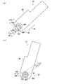
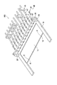
- FIG. 1 It is a typical side view of the joining apparatus concerning the embodiment of the present invention. It is a typical side view showing the joining method of the joining device concerning the embodiment of the present invention. It is a perspective view of the joining device concerning the embodiment of the present invention. It is a perspective view which shows a board
- (A) is a perspective view of the press part which concerns on embodiment of this invention.
- (B) is a side view which shows a rotating shaft holding
- (A) is a side view which shows a rotating shaft.
- (B) is sectional drawing which shows an arm attachment part. It is a perspective view which shows the rotating shaft of a wall part vicinity. It is sectional drawing which shows an arm attaching part and a rotating shaft holding
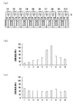
- (A) is a figure which shows the board
- (B) is a graph which shows the result of the shear strength of the board
- (C) is a graph which shows the result of the shear strength of the components joined by the joining apparatus which concerns on embodiment of this invention.
- (A) is a typical side view of the joining apparatus concerning the embodiment of the present invention.
- (B) is a typical perspective view of the joining device concerning the embodiment of the present invention. It is a typical perspective view of the joining device concerning the embodiment of the present invention.
- (A) is a typical side view of the joining apparatus concerning the embodiment of the present invention.
- (B) is a typical enlarged view of the vicinity of a contact part.
- (A) is a typical top view of the joining device concerning the embodiment of the present invention.
- (B) is a typical side view of the joining apparatus concerning the embodiment of the present invention. It is a typical side view of the press part which concerns on embodiment of this invention. It is a typical side view of the press part which concerns on embodiment of this invention.
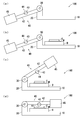
- FIG. 1 is a schematic side view of a bonding apparatus 100 according to an embodiment of the present invention.
- FIG. 2 is a schematic side view showing a bonding method of the bonding apparatus 100 according to the embodiment of the present invention.
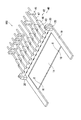
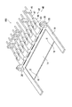
- FIG. 3 is a perspective view of the joining apparatus 100 according to the embodiment of the present invention.
- the joining device 100 includes a frame body 10, a wall portion 20, a rotating shaft 30, and a plurality of pressing portions 40.
- the joining apparatus 100 joins the component C to the substrate B through the metal material M.
- metal particles of silver, copper or nickel are dispersed.
- the metal material M is produced by mixing metal particles and a solvent such as alcohol to make a paste.
- the substrate B is, for example, a lead frame.
- the part C is, for example, a semiconductor chip.
- the part C may be a wire, for example.
- the frame body 10 supports the wall portion 20.
- the frame 10 is made of, for example, stainless steel.
- a support base 14 (FIG. 3) is attached to the frame body 10.
- the support base 14 supports the substrate B.
- the support base 14 is made of copper, for example.
- the wall portion 20 extends in the vertical direction.
- the wall portion 20 is made of, for example, stainless steel.
- Rotating shaft 30 is fixed to wall portion 20.
- the rotation shaft 30 extends in the longitudinal direction.
- the rotating shaft 30 is made of stainless steel, for example.
- the pressing unit 40 includes an arm 42, a pressing element 43, and a weight 45.
- the arm 42 extends from the rotating shaft 30.
- the arm 42 is made of stainless steel, for example.
- the arm 42 rotates around the rotation shaft 30.
- the shape of the pressing element 43 is, for example, spherical.
- the pressing element 43 has a diameter of 5 mm, for example.
- the pressing element 43 is attached to the arm 42. Specifically, half of the pressing element 43 is fitted into the arm 42, and half is exposed from the arm 42.
- the pressing element 43 presses the component C.
- the pressing element 43 has a pressing surface 44.
- the pressing surface 44 is preferably convex downward. More preferably, the pressing surface 44 is preferably a part of a spherical surface.
- the component C is joined to the substrate B by the point contact of the pressing element 43 with the component C.
- the pressing element 43 preferably joins the component C to the substrate B by making point contact with the center of the component C. Since the pressing element 43 makes point contact with the central part of the component C, the component C can be prevented from being tilted during the joining, and the entire surface of the component C can be evenly pressurized.
- the pressing element 43 is an elastic body.
- the pressing element 43 is made of, for example, Teflon (registered trademark). Since the pressing element 43 is an elastic body, it is possible to prevent the pressing element 43 from damaging the component C when the pressing element 43 presses the component C.
- the weight 45 is attached to the arm 42.
- the weight 45 is made of, for example, copper.
- the shape of the weight 45 is a rectangular parallelepiped, for example.
- a through hole 451 and a screw hole 452 are formed in the weight 45.
- the diameter of the through hole 451 is substantially equal to the diameter of the arm 42.
- the weight 45 is attached to a predetermined position of the arm 42 by inserting the arm 42 into the through hole 451 and inserting the screw 453 into the screw hole 452.
- the size of the weight 45 is set to a size that does not contact other members (for example, the frame 10) when the pressing element 43 makes point contact with the component C. Therefore, since only the pressing element 43 makes point contact with the component C, it is possible to effectively apply pressure to the component C.
- the pressing element 43 is located between the rotating shaft 30 and the weight 45.
- the lever principle works with the rotating shaft 30 as a fulcrum, the weight 45 as a force point, and the pressing element 43 as an action point. Therefore, a high pressure can be obtained even in a small space. Furthermore, by adjusting the distance from the pressing element 43 to the weight 45, the load applied to the pressing element 43 can be easily adjusted. In addition, by replacing the weight 45 with a weight 45 having a different weight, the load applied to the pressing element 43 can be easily adjusted. Furthermore, if a mechanism for changing the position of the pressing element 43 is added, the load can be adjusted even if the distance from the pressing element 43 to the rotating shaft 30 is changed.
- the substrate B and the component C are joined via the metal material M by performing the processes of FIGS.
- a bonding apparatus 100 is prepared.
- the pressing surface 44 faces upward.
- the substrate B is placed on the upper surface of the support base 14 (FIG. 3). Then, a metal material M is formed on the upper surface of the substrate B. Then, the component C is disposed on the metal material M. That is, the component C is laminated on the substrate B via the metal material M.
- the arm 42 is rotated clockwise so that the pressing element 43 makes point contact with the part C.
- the joining apparatus 100 joins the component C to the substrate B by the point contact of the pressing element 43 with the component C.
- the bonding apparatus 100 is installed in a heating furnace to sinter the metal material M and bond the component C to the substrate B.
- the component C is pressurized by stacking weights on the component C via a component pressing plate such as a glass substrate. Therefore, in order to increase the pressure, it was necessary to pile up the weights.
- the joining device 100 since the joining device 100 uses the lever principle, the height of the joining device 100 can be reduced. Therefore, the height of the heating furnace in which the bonding apparatus 100 is installed can be reduced. As a result, the metal material M can be efficiently heated to sinter the metal material.
- the thermal conductivity of the support base 14 is higher than the thermal conductivity of the arm 42. Therefore, when the metal material M is sintered, the support base 14 can easily transfer heat from below to the substrate B and the component C, and the arm 42 can hardly release heat above the substrate B and the component C. As a result, the metal material M can be efficiently heated.
- the pressing element 43 makes point contact with the part C
- the direction in which the arm 42 extends is parallel to the horizontal direction. Therefore, the height of the bonding apparatus 100 can be reduced. As a result, the height of the heating furnace in which the bonding apparatus 100 is installed can be reduced. For this reason, the metal material M can be efficiently heated to sinter the metal material.
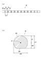
- FIG. 4 is a perspective view showing the board B and the component C.
- FIG. Fig.5 (a) is a perspective view of the press part 40 which concerns on embodiment of this invention.
- FIG. 5B is a side view showing the rotating shaft holding part 46.
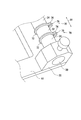
- FIG. 6A is a side view showing the rotation shaft 30.
- FIG. 6B is a cross-sectional view showing the arm attachment portion 32.
- FIG. 7 is a perspective view showing the rotation shaft 30 in the vicinity of the wall portion 20.
- FIG. 8A and FIG. 8B are cross-sectional views showing the arm attachment portion 32 and the rotating shaft holding portion 46.
- the joining apparatus 100 includes ten pressing portions 40.
- Each of the ten pressing portions 40 presses the corresponding part C among the plurality of parts C. Therefore, the joining apparatus 100 can pressurize each part C individually. For this reason, the joining apparatus 100 can set the pressure applied to the component C for each component C.
- the arm 42 has a rotating shaft holding part 46 and a weight attaching part 47.
- the rotation shaft holding unit 46 holds the rotation shaft 30.
- a weight 45 is attached to the weight attachment portion 47.
- the support base 14 is a plate-like member.
- the shape of the support base 14 is a rectangular shape.
- the support base 14 is detachable from the frame body 10.
- the support base 14 has a pair of positioning pins 16. The pair of positioning pins 16 can fix the position of the substrate B placed on the support base 14.
- positioned at the joining apparatus 100 are demonstrated.
- the unit substrates Ba are arranged in parallel in a strip shape.
- the substrate B has ten unit substrates Ba.
- a component C is disposed on each of the unit substrates Ba.
- the substrate B is provided with a plurality of guide holes H.
- the substrate B may have at least a pair of guide holes H.
- the substrate B is fixed at a predetermined position by passing each of the pair of guide holes Ha and Hb through the pair of positioning pins 16 (FIG. 3).
- the bonding apparatus 100 includes a pressing unit 40.
- the joining apparatus 100 can pressurize each part C individually. Therefore, it is possible to suppress the pressure variation for each component C.
- the thickness d ⁇ b> 1 indicates the thickness of the rotating shaft holding part 46.
- the pressing unit 40 includes an arm 42 and a pressing element 43.
- the arm 42 has a rotating shaft holding part 46 and a weight attaching part 47.
- Rotating shaft holder 46 is plate-shaped.
- the thickness d1 of the rotating shaft holding part 46 is 6 mm, for example.
- One end of the rotating shaft holding part 46 is connected to the weight attaching part 47.
- a C-shaped notch 48 is formed at the other end of the rotating shaft holding portion 46.
- a pressing element 43 is attached to the rotating shaft holding part 46.
- the weight attaching portion 47 is rod-shaped.
- the weight attaching portion 47 is cylindrical.
- a weight 45 is attached to the weight attachment portion 47.
- the center c1 indicates the center of a circle defining the arcuate portion 492.
- the radius r1 indicates the radius of a circle that defines the arcuate portion 492.
- the interval d6 indicates the interval between the first plane part 494 and the second plane part 496.
- the diameter d7 indicates the diameter of a circle that defines the arcuate portion 492.
- the length d8 indicates the length of the first plane portion 494.
- the length d9 indicates the length of the second plane portion 496.
- the rotation shaft holding part 46 has an arcuate part 492, a first flat part 494, and a second flat part 496.
- the notch 48 is defined by the arc-shaped portion 492, the first plane portion 494, and the second plane portion 496.
- the arcuate portion 492 is arcuate.
- the arcuate portion 492 is a part of a circle having a radius r1 centered on the center c1.
- the radius r1 is 5 mm, for example.
- the first flat surface portion 494 is connected to one end 493 of the arc-shaped portion 492.
- the 1st plane part 494 is planar shape.
- the second flat surface portion 496 is connected to the other end 495 of the arc-shaped portion 492.
- the 2nd plane part 496 is planar.
- Interval d6 is smaller than diameter d7.
- the interval d6 is 9 mm, for example.
- the diameter d7 is, for example, 10 mm.
- the length d8 of the first plane portion 494 is longer than the length d9 of the second plane portion 496.
- the interval d ⁇ b> 11 indicates the interval between the pair of arm movement restricting portions 70.
- the center c ⁇ b> 2 indicates the center of a circle that defines the arcuate portion 322.
- the radius r ⁇ b> 2 indicates the radius of a circle that defines the arc-shaped portion 322.
- the shortest distance d16 indicates the shortest distance from the center c2 to the plane portion 324.
- the length d17 indicates a length obtained by adding the radius r2 and the shortest distance d16.
- the diameter d18 indicates the diameter of a circle that defines the arc-shaped portion 322.
- the rotation shaft 30 includes a plurality of arm attachment portions 32, a plurality of main body portions 34, and a plurality of arm movement restriction portions 70.
- the arm attachment portion 32 has a shape in which a cylinder is partially cut away.
- An arm 42 is attached to the arm attachment portion 32.
- the main body 34 is cylindrical.
- the main body portion 34 is connected to the arm attachment portion 32 via the arm movement restriction portion 70.
- the arm movement restricting portion 70 has an annular portion 72, a protruding portion 74, and a notch 76.
- the annular portion 72 is annular.
- the protruding part 74 protrudes from the annular part 72.
- the annular portion 72 has a notch 76.
- a pair of adjacent arm movement restricting portions 70 restricts the movement of the arm 42 in the axial direction D1 of the rotating shaft 30.
- the arm attachment portion 32 is defined by a pair of arm movement restriction portions 70. That is, the pair of arm movement restricting portions 70 are provided corresponding to the arms 42.
- the distance d11 (FIG. 6A) between the pair of arm movement restricting portions 70 is substantially the same as the thickness d1 (FIG. 5A) of the rotating shaft holding portion 46.
- the peripheral surface of the arm attachment portion 32 has an arc-shaped portion 322 and a flat portion 324.
- the arc-shaped portion 322 has an arc shape.
- the arc-shaped portion 322 is a part of a circle having a radius r2 centered on the center c2.
- the radius r2 is 5 mm, for example. In the present embodiment, the radius r2 is equal to the radius r1 (FIG. 5B).
- the plane part 324 is connected to the arcuate part 322.
- the plane part 324 is planar.
- the length d17 is equal to or less than the interval d6 (FIG. 5B). In the present embodiment, the length d17 is equal to the interval d6.
- the length d17 is 9 mm, for example.
- the radius r2 is 5 mm, for example.
- the shortest distance d16 is 4 mm, for example.
- the diameter d18 is larger than the distance d6 (FIG. 5B).
- the arm 42 is preferably detachable from the rotating shaft 30.
- the diameter d18 is larger than the interval d6.
- the length d17 is not more than the interval d6.
- the length d17 and the interval d6 are substantially the same. Therefore, as shown in FIG. 8A, the rotation axis is in the direction D2 in which the plane portion 324 of the arm attachment portion 32 and the first plane portion 494 and the second plane portion 496 of the rotation axis holding portion 46 are parallel to each other. When the angle of the holding portion 46 is adjusted, the rotating shaft holding portion 46 can be attached from the arm attachment portion 32.
- the arm attachment portion 32 is passed between the first flat surface portion 494 and the second flat surface portion 496 to attach the rotation shaft holding portion 46 to the arm. It can be attached to the part 32. That is, the arm 42 can be attached to the rotation shaft 30.
- the rotation shaft holding portion 46 is rotated by turning the rotation shaft holding portion 46 so that the angle of the rotation shaft holding portion 46 is an angle other than the direction D2. It is held by the attachment portion 32. Since the diameter d18 is larger than the interval d6, it is possible to prevent the second flat surface portion 496 from being caught by the arm attachment portion 32 and the rotation shaft holding portion 46 from coming out of the arm attachment portion 32. In the present embodiment, the radius r1 and the radius r2 are equal. Therefore, the rotation shaft holding portion 46 can be smoothly rotated so that the arc-shaped portion 492 of the rotation shaft holding portion 46 follows the arc-shaped portion 322 of the arm attachment portion 32.
- the rotating shaft holding portion 46 is held by the arm mounting portion 32, and the rotating shaft is held as shown in FIG. 8A.
- the arm mounting portion 32 can be removed from the rotating shaft holding portion 46 by passing the arm mounting portion 32 between the first flat surface portion 494 and the second flat surface portion 496. . That is, the arm 42 can be detached from the rotating shaft 30.
- the arm 42 is detachable from the rotating shaft 30. Therefore, by removing the arm 42 from the rotating shaft 30, it is possible to select a joining component and join only the component C to be joined.
- the diameter d18 of the circle defining the arc-shaped portion 322 of the arm attachment portion 32 is larger than the distance d6 between the first flat portion 494 of the rotating shaft holding portion 46 and the second flat portion 496 of the rotating shaft holding portion 46. .
- the added length d17 is equal to or less than the distance d6 between the first flat surface portion 494 of the rotation shaft holding portion 46 and the second flat surface portion 496 of the rotation shaft holding portion 46.
- the rotation shaft holding portion 46 can be attached to and detached from the arm attachment portion 32 only when the rotation shaft holding portion 46 has a predetermined angle. Except for the case where the rotation shaft holding portion 46 has a predetermined angle, the rotation shaft holding portion 46 is held by the arm attachment portion 32.
- the pressing element 43 joins the component C to the substrate B through the metal material M by point contact with the component C. Therefore, a uniform pressure can be applied to the entire surface of the component C. As a result, highly reproducible bonding is possible in which variation in shear strength between the substrate B and the component C is suppressed.
- the pressing surface 44 is convex downward. Therefore, when the pressing element 43 comes into contact with the component C, a point contact can be made. As a result, a uniform pressure can be applied to the entire surface of the component C.
- the pressing element 43 joins the component C to the board B by making point contact with the central portion of the component C. Therefore, a uniform pressure can be applied to the entire surface of the component C.
- each of the at least one pressing portion 40 has a weight 45 attached to the arm.
- the pressing element 43 is located between the rotating shaft 30 and the weight 45. Therefore, in the joining apparatus 100, the lever principle works with the rotating shaft 30 as a fulcrum, the weight 45 as a force point, and the pressing element 43 as an action point. As a result, a high pressure can be obtained even in a small space. Furthermore, by adjusting the distance from the pressing element 43 to the weight 45, the load applied to the pressing element 43 can be easily adjusted. In addition, by replacing the weight 45 with a weight 45 having a different weight, the load applied to the pressing element 43 can be easily adjusted. Furthermore, if a mechanism for changing the position of the pressing element 43 is added, the load can be adjusted even if the distance from the pressing element 43 to the rotating shaft 30 is changed.
- the arm 42 is detachable from the rotating shaft 30. Therefore, by removing the arm 42 from the rotating shaft 30, it is possible to select a joining component and join only the component C to be joined.
- the bonding apparatus 100 includes the support base 14 that supports the substrate B. Further, the support base 14 fixes the position of the substrate B. Therefore, the position of the substrate B can be fixed so that the pressing element 43 makes point contact with the center of the component C. Therefore, a uniform pressure can be applied to the entire surface of the component C.
- the thermal conductivity of the support base 14 is higher than the thermal conductivity of the arm 42. Therefore, when the metal material M is sintered, the support base 14 can easily transfer heat from below to the substrate B and the component C, and the arm 42 can hardly release heat above the substrate B and the component C. As a result, the metal material M can be efficiently heated. Moreover, even if the pressing element 43 is made of a fluororesin having heat resistance and low thermal conductivity, even if the pressing element 43 is in direct contact with the component C, it is difficult for heat to escape, and heating can be performed more efficiently.
- the extending direction of the arm 42 is parallel to the horizontal direction. Therefore, the height of the bonding apparatus 100 can be reduced. As a result, the height of the heating furnace in which the bonding apparatus 100 is installed can be reduced. For this reason, the metal material M can be efficiently heated to sinter the metal material.
- the pressing element 43 is an elastic body. Therefore, when the pressing element 43 presses the component C, it can be suppressed that the pressing element 43 damages the component C.
- the joining apparatus 100 includes at least a plurality of pressing portions 40.
- Each of the plurality of pressing portions 40 presses the corresponding part C among the plurality of parts C. Therefore, the joining apparatus 100 can pressurize each part C individually. For this reason, the joining apparatus 100 can set the pressure applied to the component C for each component C.
- FIG. 9A is a diagram showing the substrate B and the component C joined by the joining apparatus 100 according to the embodiment of the present invention.
- FIG. 9B is a graph showing the result of the shear strength between the substrate B and the component C bonded by the conventional method.
- FIG.9 (c) is a graph which shows the result of the shear strength of the components C joined by the joining apparatus 100 which concerns on embodiment of this invention.
- 9 (b) and 9 (c) the horizontal axis indicates the number of the part C, and the vertical axis indicates the shear strength.
- the joining apparatus 100 adjusted the weight and position of the weight 45 using the joining apparatus 100 shown in FIG. As shown in FIG. 9A, ten 1.85 mm ⁇ SiC Schottky barrier diodes (component C) were joined to the TO247 lead frame (substrate B).
- the joining apparatus 100 was installed in a vacuum furnace (RSS-450-210) manufactured by UNITEMP. Since the distance between the chips was 17.5 mm, ten arms 42 were arranged according to this pitch. A silver paste was used as the die attach material (metal material M).
- a weight 45 was fixed to the arm 42 so that a load of 140 g (0.4 MPa) was applied to the chip center during sintering.
- the TO247 frame was inserted into the two positioning pins 16 provided on the support base 14 for positioning and fixing.
- the arm 42 has one pressing element 43, but the present invention is not limited to this.
- the arm 42 may have two or more pressing elements 43.
- FIG. 10 is a perspective view of the joining apparatus 100 according to the embodiment of the present invention.
- Each of the arms 42 has two pressing elements 43.
- the two pressing elements 43 are in point contact with different parts C, respectively. Therefore, pressure can be applied to the components C in various arrangements on the substrate B.
- each of the arms 42 includes a plurality of pressing elements 43, it is preferable that the pressing elements 43 be configured to be flexible.
- FIG. 11 is a schematic side view of the arm 42. As shown in FIG. 11, the arm 42 further includes a presser holding portion 462.
- the presser holding part 462 includes a movable part 464 and a presser attaching part 466.
- the movable part 464 is attached to the rotating shaft holding part 46.
- the movable portion 464 is movable back and forth and left and right around a fixed point fixed to the rotating shaft holding portion 46.
- the presser attachment portion 466 is attached to the movable portion 464.
- Two pressing elements 43 are attached to the pressing element mounting portion 466.
- the pusher mounting portion 466 moves corresponding to the movement of the movable portion 464. Accordingly, the plurality of parts C can be evenly pressed by the plurality of pressing elements 43 provided on one arm 42.
- the three pressing elements 43 are arrange
- the pressing portion 40 has one arm 42 or one pressing member holding portion 462, but the present invention is not limited to this.
- the pressing unit 40 may have two or more arms 42.
- FIG. 12 is a perspective view of the joining apparatus 100 according to the embodiment of the present invention.
- Each of the pressing portions 40 includes two arms 42 and two pressing elements 43.
- Each of the pressing portions 40 is partially connected to the arm 42. Therefore, two pressing elements 43 can be brought into point contact with the component C at a time by rotating the arm 42.
- the pressing element 43 similarly to the bonding apparatus 100 described with reference to FIG. 10, it is preferable that the pressing element 43 be flexibly movable as described with reference to FIG. 11. Accordingly, it is possible to apply pressure evenly to the plurality of components C.
- FIG. 13 is a schematic side view of the pressing portion 40 according to the embodiment of the present invention.
- the presser 43 shown in FIG. 13B is arranged so as to be shifted in the direction in which the arm 42 extends (hereinafter referred to as the arm direction) from the presser 43 shown in FIG. Therefore, even if the component C is displaced in the arm direction with respect to the substrate B, the component C can be joined to the substrate B by disposing the pressing element 43 in the arm direction.
- the pressing element 43 shown in FIG. 13 (c) is longer in the height direction than the pressing element 43 shown in FIG. 13 (a). That is, the pressing surface 44 of the pressing element 43 shown in FIG. 13C is positioned lower than the pressing surface 44 of the pressing element 43 shown in FIG. Therefore, even if the thickness of the substrate B or the component C is different, the component C can be joined to the substrate B by changing the length of the pressing element 43 in the height direction.
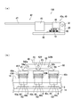
- the length in the height direction of the rotation shaft holding portion 46 shown in FIG. 13 (d) is longer than the length in the height direction of the rotation shaft holding portion 46 shown in FIG. 13 (a). Therefore, even if the substrate B or the component C is thin, the component C can be joined to the substrate B by changing the length in the height direction of the rotation shaft holding portion 46.
- FIG. 14 is a typical side view of the joining apparatus 100 which concerns on embodiment of this invention.
- FIG. 14B is a schematic perspective view of the bonding apparatus 100 according to the embodiment of the present invention. The description of the overlapping parts with the bonding apparatus 100 described with reference to FIGS. 1 to 13 is omitted.
- the joining device 100 includes a frame 10, a wall 20, a first rotating shaft 30a, a second rotating shaft 30b, and a third time.
- the moving shaft 30c, the 1st press part 40a, the 2nd press part 40b, and the 3rd press part 40c are provided.
- the frame body 10 supports the wall portion 20.
- the wall portion 20 extends in the vertical direction.
- the first rotation shaft 30a, the second rotation shaft 30b, and the third rotation shaft 30c are fixed to the wall portion 20.
- the positions of the first rotation shaft 30a, the second rotation shaft 30b, and the third rotation shaft 30c in the height direction are different.
- the positions of the first rotation shaft 30a, the second rotation shaft 30b, and the third rotation shaft 30c in the arm direction are different.
- the first pressing portion 40a extends from the first rotating shaft 30a.
- the second pressing portion 40b extends from the second rotation shaft 30b.
- the third pressing portion 40c extends from the third rotation shaft 30c.
- the first pressing portion 40a has a first arm 42a, a first pressing element 43a, and a weight 45a.
- the second pressing portion 40b includes a second arm 42b, a second pressing element 43b, and a weight 45b.
- the third pressing part 40c includes a third arm 42c, a third pressing element 43c, and a weight 45c.
- the first pressing element 43a, the second pressing element 43b, and the third pressing element 43c have different lengths in the height direction. Specifically, the length in the height direction becomes longer in the order of the first pressing element 43a, the second pressing element 43b, and the third pressing element 43c.
- the pressing surface 44a of the first pressing element 43a, the pressing surface 44b of the second pressing element 43b, The length in the height direction of the first pressing element 43a, the second pressing element 43b, and the third pressing element 43c is set so that the position in the height direction with the pressing surface 44c of the third pressing element 43c is the same. ing.
- An opening 49b is formed in the second arm 42b.
- the first pressing element 43a can pass through the opening 49b.
- An opening 49c is formed in the third arm 42c.
- the first pressing element 43a and the second pressing element 43b can pass through the opening 49c. Therefore, after the third arm 42c is rotated, the second arm 42b can be rotated so that the second pressing element 43b passes through the opening 49c. Then, after the second arm 42b is rotated, the first arm 42a can be rotated so that the first pressing element 43a passes through the opening 49b and the opening 49c.
- the pressing surface 44a of the first pressing element 43a, the pressing surface 44b of the second pressing element 43b, The height direction position of the third pressing element 43c and the pressing surface 44c is the same. Further, the pressing surface 44a of the first pressing element 43a, the pressing surface 44b of the second pressing element 43b, and the pressing surface 44c of the third pressing element 43c are arranged side by side in the arm direction. Therefore, a plurality of components C arranged in the arm direction can be bonded to the substrate B.
- first pressing portion 40a, the second pressing portion 40b, the third pressing portion 40c the direction in which the first rotating shaft 30a, the second rotating shaft 30b, and the third rotating shaft 30c extend.
- the components C arranged in a matrix on the substrate B can be joined.
- three each of the first pressing part 40a, the second pressing part 40b, and the third pressing part 40c three in the vertical direction and three in the horizontal direction on the substrate B.
- the arranged components C (a total of nine components C) can be bonded to the substrate B.
- the second arm 42b of the second pressing portion 40b is formed with an opening 49b through which the first pressing element 43a of the first pressing portion 40a can pass. Therefore, when the first arm 42a is rotated, the first pressing element 43a can be passed through the opening 49b. As a result, a plurality of components C arranged in the arm direction can be bonded to the substrate B.
- the pressing element 43 attached to the pressing portion 40 comes into contact with the component C to join the component C to the board B.
- the component C may be joined to the board B by the arm 42 rotating from the state where the arm 42 and the pressing element 43 are separated, and the pressing element 43 coming into contact with the arm 42.
- FIG. 15 is a schematic perspective view of the joining apparatus 100 according to the embodiment of the present invention.
- FIG. 16A is a schematic side view of the bonding apparatus 100 according to the embodiment of the present invention.
- FIG. 16B is a schematic enlarged view in the vicinity of the contact portion 50.
- the contact point P1 shows the point where the 1st end movable part 54a and the presser 43a contact
- the contact point P2 is the point where the 1st end movable part 54a and the presser 43b contact.
- the contact point P3 indicates a point where the second end movable part 54b and the pressing element 43b contact each other
- the contact point P4 indicates a point where the second end movable part 54b and the pressing element 43c contact each other.
- the joining device 100 includes a frame 10, a wall 20, a rotating shaft 30, a first pressing part 40a, a second pressing part 40b, and a third.
- the pressing part 40c, the support base 14, and the plate-shaped member 18 are provided.
- Each of the arm 42 of the first pressing portion 40a, the arm 42 of the second pressing portion 40b, and the arm 42 of the third pressing portion 40c has a contact portion 50.
- Each of the first pressing portion 40a, the second pressing portion 40b, and the third pressing portion 40c has three pressing elements 43.
- the pressing element 43 is disposed on the plate-like member 18.
- the contact part 50 includes a connection movable part 52, a first end movable part 54a, and a second end movable part 54b.
- the connection movable part 52 is attached to the rotating shaft holding part 46.
- the connection movable part 52 has a shaft 522.
- the connection movable part 52 is movable around the shaft 522.
- the first end movable portion 54a has a shaft 542a (fixed point).
- the first end movable portion 54a is movable around the shaft 542a.
- the second end movable portion 54b has a shaft 542b (fixed point).
- the second end movable portion 54b is movable around the shaft 542b.
- the contact part 50 is in contact with the pressing element 43.
- the first end movable part 54 a and the second end movable part 54 b are in contact with the pressing element 43.
- the pressing element 43 is in point contact with the movable parts 54a and 54b, whereby the pressing element 43 and the component C are in contact with each other, and the component C is bonded to the substrate B.
- one end of the first end movable portion 54a makes point contact with the pressing element 43a at the contact point P1.
- the other end of the first end movable portion 54a makes point contact with the pressing element 43b at the contact point P2.
- one end of the second end movable portion 54b makes point contact with the pressing element 43c at the contact point P4.
- the other end of the second end movable portion 54b makes point contact with the pressing element 43b at the contact point P3. Accordingly, a load is evenly applied to the pressing surface 44a, the pressing surface 44b, and the pressing surface 44c. As a result, a plurality of components C arranged in the arm direction can be bonded to the substrate B. In the present embodiment, since three pressing portions 40 are arranged in the axial direction of the rotation shaft 30, the components C arranged in a matrix on the substrate B can be joined.
- Each of the pressing element 43a, the pressing element 43b, and the pressing element 43c has a large diameter part 412 and a small diameter part 414.
- the diameter of the large diameter portion 412 is larger than the diameter of the small diameter portion 414.
- the large diameter portion 412 and the small diameter portion 414 are, for example, cylindrical.
- the height of the small diameter portion 414 is higher than the height of the large diameter portion 412.
- the pressing surface 44 is planar.
- the pressing surface 44 may be a part of a spherical surface.
- the plate-like member 18 is attached to the frame body 10.
- the plate-like member 18 is disposed above the support base 14.
- a through hole 182 is formed in the plate member 18.
- the diameter of the through hole 182 is larger than the diameter of the small diameter portion 414. Therefore, the small diameter portion 414 can pass through the through hole 182.
- the diameter of the through hole 182 is smaller than the diameter of the large diameter portion 412.
- the elastic member 60a, the elastic member 60b, and the elastic member 60c are, for example, springs.
- An elastic member 60a is attached to the pressing element 43a.
- An elastic member 60b is attached to the pressing element 43b.
- An elastic member 60c is attached to the pressing element 43c.
- one end of the elastic member 60 a is attached to the large-diameter portion 412 and is arranged so as to surround a part of the small-diameter portion 414.
- the diameter of the elastic member 60a, the diameter of the elastic member 60b, and the diameter of the elastic member 60c are larger than the diameter of the small diameter portion 414.
- the diameter of the elastic member 60a, the diameter of the elastic member 60b, and the diameter of the elastic member 60c are larger than the diameter of the through hole 182. Therefore, the elastic member 60a, the elastic member 60b, and the elastic member 60c cannot pass through the through hole 182.
- the contact of the contact portion 50 with the pressing element 43 is lost by rotating the arm 42, that is, when the load applied to the pressing element 43 by the contact portion 50 is lost, the pressing is performed by the elastic member 60.
- the child 43 is pushed up.
- the board B and the component C can be easily arranged on the support base 14.
- the component 43 is joined to the substrate B by the presser 43 making point contact with the movable parts 54 a and 54 b. Accordingly, the plurality of parts C can be evenly pressed by the plurality of pressing elements 43 provided on one arm 42.
- the contact portion 50 has a plurality of movable portions (a connection movable portion 52, a first end movable portion 54a, and a second end movable portion 54b).
- the present invention is not limited to this as long as the movable part can contact the pressing element 43.
- the contact part 50 may have only one movable part.
- FIG. 17A is a schematic top view of the bonding apparatus 100 according to the embodiment of the present invention.
- FIG. 17B is a schematic side view of the bonding apparatus 100 according to the embodiment of the present invention.
- the axial direction D ⁇ b> 1 indicates the axial direction of the rotating shaft 30.
- the direction D2 indicates the arm direction.
- a direction D3 indicates a vertical direction.
- the joining apparatus 100 preferably includes a position adjustment mechanism that enables the pressing portion 40 to move in the axial direction D1. Moreover, it is preferable that the joining apparatus 100 is provided with the position adjustment mechanism which enables the movement of the press part 40 to the direction D2. Therefore, the position where the pressing unit 40 presses the component C can be changed. As a result, the degree of freedom of arrangement of the component C arranged on the board B is improved.
- the joining apparatus 100 preferably includes a position adjustment mechanism that enables the pressing portion 40 to move in the direction D3. Therefore, the substrate B and the component C can be joined even when the heights of the substrate B and the component C are different without changing the shape of the support base 14.
- FIG. 18 is a schematic side view of the pressing portion 40 according to the embodiment of the present invention.
- a contact point P ⁇ b> 11 indicates a point where the arm 42 and the pressing element 43 come into contact.
- the description of the overlapping parts with the joining apparatus 100 described with reference to FIGS. 1 to 17 is omitted.
- the pressing element 43 is not attached to the arm 42. That is, the arm 42 and the pressing element 43 can be separated. In this embodiment, it is preferable that the pressing element 43 has rigidity. In the present embodiment, the pressing surface 44 is a flat surface.
- the pressing element 43 When joining the component C to the board B, first, the pressing element 43 is arranged on the board B. Then, by rotating the arm 42, the pressing element 43 and the arm 42 are brought into point contact at the contact point P11. In this embodiment, the point contact portion is convex upward. Therefore, the entire surface of the component C can be evenly pressurized via the pressing element 43. In the present embodiment, the pressing element 43 has rigidity. Therefore, even a component C with low rigidity such as a thin layer chip can be bonded to the substrate B.
- FIG. 19 is a schematic side view of the pressing portion 40 according to the embodiment of the present invention.
- the contact point P ⁇ b> 21 indicates a point where the substrate support member 90 and the reference surface 142 are in contact with each other. The description of the overlapping parts with the bonding apparatus 100 described with reference to FIGS. 1 to 18 is omitted.
- the pressing portion 40 includes an arm 42 and a substrate support member 90.
- the substrate support member 90 supports the substrate B.
- the substrate support member 90 has a flat portion 92 and a hemispherical portion 94.
- the flat part 92 is flat.
- the hemispherical portion 94 is hemispherical.
- the support base 14 has a reference surface 142.
- a recess 144 is formed in the reference surface 142.
- the substrate support member 90 is disposed on the reference surface 142. Specifically, a part of the hemispherical portion 94 is disposed in the concave portion 144.
- the substrate support member 90 is movably supported by the recess 144.
- a suction hole is formed in the recess 144.
- the substrate support member 90 can be fixed by sucking the substrate support member 90 from the suction hole by the suction mechanism.
- the substrate B and the component C are arranged on the substrate support member 90. Then, the arm 42 presses the component C by rotating the arm 42. At this time, the substrate support member 90 is stabilized at a position where a load is evenly applied to the entire surface of the component C. Here, the substrate support member 90 makes point contact with the reference surface 142 at the contact point P21. After the position of the substrate support member 90 is stabilized, the substrate support member 90 is fixed by sucking the substrate support member 90 from the suction hole by the suction mechanism.
- the component C is joined to the substrate B when the substrate support member 90 makes point contact with the reference surface 142. Accordingly, the entire surface of the component C can be evenly pressurized.
- the pressing element 43 is formed of a fluorine-based resin such as Teflon (registered trademark).
- Teflon registered trademark
- the present invention is not limited to this.
- the pressing element 43 may be formed of a ceramic or a metal material.
- the pressing element 43 is formed of a ceramic or a metal material, it can be sintered and bonded at a higher temperature than when the pressing element 43 is formed of Teflon (registered trademark).
- the pressing portion 40 has the weight 45, but the present invention is not limited to this.
- the pressing part 40 may not have the weight 45.
- pressure can be applied to the component C by the weight of the arm 42.
- joining without pressure can be performed.
Landscapes
- Engineering & Computer Science (AREA)
- Mechanical Engineering (AREA)
- Die Bonding (AREA)
- Electric Connection Of Electric Components To Printed Circuits (AREA)
- Pressure Welding/Diffusion-Bonding (AREA)
Abstract
Description
20 壁部
30 回動軸
32 アーム取付部
40 押圧部
40a 第1押圧部
40b 第2押圧部
42 アーム
43 押圧子
44 押圧面
45 重り
46 回動軸保持部
49b、49c 開口
50 接触部
52 接続可動部
54a 第1端可動部(可動部)
54b 第2端可動部(可動部)
70 アーム移動規制部
90 基板支持部材
100 接合装置
142 基準面
322 円弧状部
324 平面部
492 円弧状部
494 第1平面部
496 第2平面部
B 基板
C 部品
H ガイド孔
M 金属材料
Claims (15)
- 金属材料を介して基板に部品を接合する接合装置であって、
壁部と、
少なくとも1つの押圧部と、
前記壁部に固定される回動軸と
を備え、
前記少なくとも1つの押圧部の各々は、
前記回動軸から延び、前記回動軸の回りに回動するアームと、
前記部品を押圧する押圧子、または、基準面に配置され前記基板を支持する基板支持部材と
を有し、
前記押圧子が前記部品と点接触すること、前記押圧子が前記アームと点接触すること、または前記基板支持部材が前記基準面と点接触することによって、前記基板に前記部品を接合する、接合装置。 - 前記押圧子は、前記部品を押圧する押圧面を有し、
前記押圧面は下に凸である、請求項1に記載の接合装置。 - 前記押圧面は球面の一部である、請求項2に記載の接合装置。
- 前記押圧子は、前記部品の中心部と点接触することによって、前記基板に前記部品を接合する、請求項1から請求項3のいずれか1項に記載の接合装置。
- 前記少なくとも1つの押圧部の各々は、前記アームに取り付けられる重りをさらに有し、
前記押圧子は、前記回動軸と前記重りとの間に位置する、請求項1から請求項4のいずれか1項に記載の接合装置。 - 前記アームは、前記回動軸から着脱可能である、請求項1から請求項5のいずれか1項に記載の接合装置。
- 前記回動軸は、前記アームが取り付けられるアーム取付部を有し、
前記アーム取付部は、円柱が一部切り欠かれた形状を有し、
前記アーム取付部には、前記アームが取り付けられ、
前記アーム取付部の周面は、
円弧状の円弧状部と、
前記円弧状部と接続する平面状の平面部と
を有し
前記アームは、回動軸保持部を有し、
前記回動軸保持部は、
円弧状の円弧状部と、
前記円弧状部の一端と接続する平面状の第1平面部と、
前記円弧状部の他端と接続する平面状の第2平面部とを有し、
前記アーム取付部の前記円弧状部を規定する円の直径は、前記回動軸保持部の前記第1平面部と前記回動軸保持部の前記第2平面部との間隔よりも大きく、
前記アーム取付部の前記円弧状部を規定する円の半径と前記アーム取付部の前記円弧状部を規定する円の中心から前記アーム取付部の前記平面部までの最短距離とを加えた長さは、前記回動軸保持部の前記第1平面部と前記回動軸保持部の前記第2平面部との間隔以下である、請求項6に記載の接合装置。 - 前記回動軸は、前記回動軸の軸方向への前記アームの移動を規制する一対のアーム移動規制部をさらに有し、
前記アーム取付部は、前記一対のアーム移動規制部によって規定される、請求項7に記載の接合装置。 - 前記基板を支持する支持台をさらに備え、
前記支持台は、前記基板の位置を固定し、
前記支持台の熱伝導率は、前記アームの熱伝導率よりも高い、請求項1から請求項8のいずれか1項に記載の接合装置。 - 前記押圧子が前記部品と点接触する際、前記アームが延びる方向は、水平方向に平行である、請求項1から請求項9のいずれか1項に記載の接合装置。
- 前記押圧子は弾性体である、請求項1から請求項10のいずれか1項に記載の接合装置。
- 前記弾性体は、フッ素系樹脂を含む、請求項11に記載の接合装置。
- 前記部品は複数であり、
前記少なくとも1つの押圧部は複数であり、
複数の前記押圧部の各々は、複数の前記部品のうち対応する前記部品を押圧する、請求項1から請求項12のいずれか1項に記載の接合装置。 - 少なくとも1つの押圧部は第1押圧部と第2押圧部とを有し、
前記第2押圧部の前記アームには、前記第1押圧部の前記押圧子が通過可能な開口が形成されている、請求項1から請求項13のいずれか1項に記載の接合装置。 - 前記アームは、前記押圧子と接触する接触部をさらに有し、
前記接触部は固定点を中心にして可動である可動部を有し、
前記押圧子が前記可動部と点接触することによって、前記基板に前記部品を接合する、請求項1から請求項14のいずれか1項に記載の接合装置。
Priority Applications (3)
| Application Number | Priority Date | Filing Date | Title |
|---|---|---|---|
| EP17839058.9A EP3499551A4 (en) | 2016-08-12 | 2017-06-16 | BONDINGVORRICHTUNG |
| US16/324,528 US11049840B2 (en) | 2016-08-12 | 2017-06-16 | Bonding device |
| JP2018532853A JP6786076B2 (ja) | 2016-08-12 | 2017-06-16 | 接合装置 |
Applications Claiming Priority (2)
| Application Number | Priority Date | Filing Date | Title |
|---|---|---|---|
| JP2016-158565 | 2016-08-12 | ||
| JP2016158565 | 2016-08-12 |
Publications (1)
| Publication Number | Publication Date |
|---|---|
| WO2018029983A1 true WO2018029983A1 (ja) | 2018-02-15 |
Family
ID=61162128
Family Applications (1)
| Application Number | Title | Priority Date | Filing Date |
|---|---|---|---|
| PCT/JP2017/022285 Ceased WO2018029983A1 (ja) | 2016-08-12 | 2017-06-16 | 接合装置 |
Country Status (4)
| Country | Link |
|---|---|
| US (1) | US11049840B2 (ja) |
| EP (1) | EP3499551A4 (ja) |
| JP (1) | JP6786076B2 (ja) |
| WO (1) | WO2018029983A1 (ja) |
Cited By (1)
| Publication number | Priority date | Publication date | Assignee | Title |
|---|---|---|---|---|
| WO2021166627A1 (ja) | 2020-02-19 | 2021-08-26 | 株式会社ダイセル | 金属粒子焼結用分散媒及び導電ペースト |
Citations (5)
| Publication number | Priority date | Publication date | Assignee | Title |
|---|---|---|---|---|
| JPS6150338A (ja) * | 1984-08-20 | 1986-03-12 | Toshiba Corp | マウント装置 |
| JPH09246296A (ja) * | 1996-03-08 | 1997-09-19 | Tosok Corp | 対象物への荷重機構 |
| JP2004281476A (ja) * | 2003-03-13 | 2004-10-07 | Matsushita Electric Ind Co Ltd | 倣い装置およびそれを用いた接合装置 |
| JP2007294608A (ja) * | 2006-04-24 | 2007-11-08 | Canon Machinery Inc | フィルムマウント用コレットおよびフィルムマウント方法 |
| JP2011071301A (ja) | 2009-09-25 | 2011-04-07 | Honda Motor Co Ltd | 金属ナノ粒子を用いた接合方法及び接合体 |
Family Cites Families (7)
| Publication number | Priority date | Publication date | Assignee | Title |
|---|---|---|---|---|
| US3186446A (en) * | 1961-05-09 | 1965-06-01 | Sylvania Electric Prod | Apparatus for attaching filamentary material |
| US3738560A (en) * | 1970-12-08 | 1973-06-12 | Kulicke & Soffa Ind Inc | Semiconductor die bonder |
| US4551965A (en) * | 1983-04-06 | 1985-11-12 | Doboy Verpackungsmaschinen Gmbh | Welding and separating apparatus for plastic films |
| US5603445A (en) * | 1994-02-24 | 1997-02-18 | Hill; William H. | Ultrasonic wire bonder and transducer improvements |
| JP3393527B2 (ja) * | 1999-04-16 | 2003-04-07 | 日本電信電話株式会社 | はんだバンプの接続方法及び加圧治具 |
| KR101335275B1 (ko) | 2007-07-20 | 2013-11-29 | 삼성전자주식회사 | 반도체 칩 본딩 장치 |
| JP5580163B2 (ja) | 2010-10-13 | 2014-08-27 | 東レエンジニアリング株式会社 | 実装装置の平行度調整方法および平行度調整装置 |
-
2017
- 2017-06-16 EP EP17839058.9A patent/EP3499551A4/en active Pending
- 2017-06-16 US US16/324,528 patent/US11049840B2/en not_active Expired - Fee Related
- 2017-06-16 WO PCT/JP2017/022285 patent/WO2018029983A1/ja not_active Ceased
- 2017-06-16 JP JP2018532853A patent/JP6786076B2/ja active Active
Patent Citations (5)
| Publication number | Priority date | Publication date | Assignee | Title |
|---|---|---|---|---|
| JPS6150338A (ja) * | 1984-08-20 | 1986-03-12 | Toshiba Corp | マウント装置 |
| JPH09246296A (ja) * | 1996-03-08 | 1997-09-19 | Tosok Corp | 対象物への荷重機構 |
| JP2004281476A (ja) * | 2003-03-13 | 2004-10-07 | Matsushita Electric Ind Co Ltd | 倣い装置およびそれを用いた接合装置 |
| JP2007294608A (ja) * | 2006-04-24 | 2007-11-08 | Canon Machinery Inc | フィルムマウント用コレットおよびフィルムマウント方法 |
| JP2011071301A (ja) | 2009-09-25 | 2011-04-07 | Honda Motor Co Ltd | 金属ナノ粒子を用いた接合方法及び接合体 |
Non-Patent Citations (1)
| Title |
|---|
| See also references of EP3499551A4 |
Cited By (1)
| Publication number | Priority date | Publication date | Assignee | Title |
|---|---|---|---|---|
| WO2021166627A1 (ja) | 2020-02-19 | 2021-08-26 | 株式会社ダイセル | 金属粒子焼結用分散媒及び導電ペースト |
Also Published As
| Publication number | Publication date |
|---|---|
| JPWO2018029983A1 (ja) | 2019-06-06 |
| US11049840B2 (en) | 2021-06-29 |
| EP3499551A1 (en) | 2019-06-19 |
| JP6786076B2 (ja) | 2020-11-18 |
| EP3499551A4 (en) | 2019-11-27 |
| US20190189587A1 (en) | 2019-06-20 |
Similar Documents
| Publication | Publication Date | Title |
|---|---|---|
| JP5701465B2 (ja) | フリップチップボンダ及びボンディングステージの平坦度並びに変形量補正方法 | |
| JP4941305B2 (ja) | 接合装置 | |
| JP6591426B2 (ja) | 実装用ヘッドおよびそれを用いた実装装置 | |
| JP6129353B2 (ja) | 加圧ユニット | |
| JP2011009357A (ja) | 実装装置 | |
| JP7604779B2 (ja) | 半導体製造装置及び半導体装置の製造方法 | |
| JP2009272464A (ja) | サンプル保持機構 | |
| WO2018029983A1 (ja) | 接合装置 | |
| JP2018026375A (ja) | 実装装置 | |
| KR101579094B1 (ko) | 본딩 스테이지 및 그 제조 방법 | |
| TWI850178B (zh) | 加壓裝置 | |
| JP5018251B2 (ja) | 回路基板の製造方法および回路基板の製造装置 | |
| JP5577585B2 (ja) | 基板保持部材、接合装置および接合方法 | |
| JP6512182B2 (ja) | 半導体装置の製造方法 | |
| JP6190895B2 (ja) | 伝達部材及び加圧ユニット | |
| JP3775960B2 (ja) | 電子部品の圧着装置および圧着方法 | |
| JP2012089658A (ja) | フラットパネルディスプレイの実装圧着装置 | |
| JP6210904B2 (ja) | 電極印刷装置及び電極印刷方法 | |
| JP5214381B2 (ja) | はんだ付け装置およびはんだ付け方法 | |
| TW202614278A (zh) | 搭載裝置 | |
| JP2008078462A (ja) | 圧着装置、圧着方法及び圧着物の製造方法 | |
| JP2007253593A (ja) | スクリーン印刷方法 | |
| JP2008205049A (ja) | 圧着装置 | |
| JP2014027127A (ja) | ワーク支持装置及びデバイスの製造方法 |
Legal Events
| Date | Code | Title | Description |
|---|---|---|---|
| 121 | Ep: the epo has been informed by wipo that ep was designated in this application |
Ref document number: 17839058 Country of ref document: EP Kind code of ref document: A1 |
|
| ENP | Entry into the national phase |
Ref document number: 2018532853 Country of ref document: JP Kind code of ref document: A |
|
| NENP | Non-entry into the national phase |
Ref country code: DE |
|
| ENP | Entry into the national phase |
Ref document number: 2017839058 Country of ref document: EP Effective date: 20190312 |
|
| WWW | Wipo information: withdrawn in national office |
Ref document number: 2017839058 Country of ref document: EP |