WO2018026006A1 - 弁付き針組立体および留置針組立体 - Google Patents
弁付き針組立体および留置針組立体 Download PDFInfo
- Publication number
- WO2018026006A1 WO2018026006A1 PCT/JP2017/028442 JP2017028442W WO2018026006A1 WO 2018026006 A1 WO2018026006 A1 WO 2018026006A1 JP 2017028442 W JP2017028442 W JP 2017028442W WO 2018026006 A1 WO2018026006 A1 WO 2018026006A1
- Authority
- WO
- WIPO (PCT)
- Prior art keywords
- needle
- connector
- valve
- cap
- end side
- Prior art date
- Legal status (The legal status is an assumption and is not a legal conclusion. Google has not performed a legal analysis and makes no representation as to the accuracy of the status listed.)
- Ceased
Links
Images


Classifications
-
- A—HUMAN NECESSITIES
- A61—MEDICAL OR VETERINARY SCIENCE; HYGIENE
- A61M—DEVICES FOR INTRODUCING MEDIA INTO, OR ONTO, THE BODY; DEVICES FOR TRANSDUCING BODY MEDIA OR FOR TAKING MEDIA FROM THE BODY; DEVICES FOR PRODUCING OR ENDING SLEEP OR STUPOR
- A61M25/00—Catheters; Hollow probes
- A61M25/01—Introducing, guiding, advancing, emplacing or holding catheters
- A61M25/06—Body-piercing guide needles or the like
- A61M25/0612—Devices for protecting the needle; Devices to help insertion of the needle, e.g. wings or holders
- A61M25/0618—Devices for protecting the needle; Devices to help insertion of the needle, e.g. wings or holders having means for protecting only the distal tip of the needle, e.g. a needle guard
-
- A—HUMAN NECESSITIES
- A61—MEDICAL OR VETERINARY SCIENCE; HYGIENE
- A61M—DEVICES FOR INTRODUCING MEDIA INTO, OR ONTO, THE BODY; DEVICES FOR TRANSDUCING BODY MEDIA OR FOR TAKING MEDIA FROM THE BODY; DEVICES FOR PRODUCING OR ENDING SLEEP OR STUPOR
- A61M39/00—Tubes, tube connectors, tube couplings, valves, access sites or the like, specially adapted for medical use
- A61M39/02—Access sites
- A61M39/06—Haemostasis valves, i.e. gaskets sealing around a needle, catheter or the like, closing on removal thereof
-
- A—HUMAN NECESSITIES
- A61—MEDICAL OR VETERINARY SCIENCE; HYGIENE
- A61M—DEVICES FOR INTRODUCING MEDIA INTO, OR ONTO, THE BODY; DEVICES FOR TRANSDUCING BODY MEDIA OR FOR TAKING MEDIA FROM THE BODY; DEVICES FOR PRODUCING OR ENDING SLEEP OR STUPOR
- A61M25/00—Catheters; Hollow probes
- A61M25/01—Introducing, guiding, advancing, emplacing or holding catheters
- A61M25/06—Body-piercing guide needles or the like
-
- A—HUMAN NECESSITIES
- A61—MEDICAL OR VETERINARY SCIENCE; HYGIENE
- A61M—DEVICES FOR INTRODUCING MEDIA INTO, OR ONTO, THE BODY; DEVICES FOR TRANSDUCING BODY MEDIA OR FOR TAKING MEDIA FROM THE BODY; DEVICES FOR PRODUCING OR ENDING SLEEP OR STUPOR
- A61M39/00—Tubes, tube connectors, tube couplings, valves, access sites or the like, specially adapted for medical use
- A61M39/10—Tube connectors; Tube couplings
- A61M39/1011—Locking means for securing connection; Additional tamper safeties
-
- A—HUMAN NECESSITIES
- A61—MEDICAL OR VETERINARY SCIENCE; HYGIENE
- A61M—DEVICES FOR INTRODUCING MEDIA INTO, OR ONTO, THE BODY; DEVICES FOR TRANSDUCING BODY MEDIA OR FOR TAKING MEDIA FROM THE BODY; DEVICES FOR PRODUCING OR ENDING SLEEP OR STUPOR
- A61M5/00—Devices for bringing media into the body in a subcutaneous, intra-vascular or intramuscular way; Accessories therefor, e.g. filling or cleaning devices, arm-rests
- A61M5/14—Infusion devices, e.g. infusing by gravity; Blood infusion; Accessories therefor
- A61M5/158—Needles for infusions; Accessories therefor, e.g. for inserting infusion needles, or for holding them on the body
- A61M2005/1587—Needles for infusions; Accessories therefor, e.g. for inserting infusion needles, or for holding them on the body suitable for being connected to an infusion line after insertion into a patient
-
- A—HUMAN NECESSITIES
- A61—MEDICAL OR VETERINARY SCIENCE; HYGIENE
- A61M—DEVICES FOR INTRODUCING MEDIA INTO, OR ONTO, THE BODY; DEVICES FOR TRANSDUCING BODY MEDIA OR FOR TAKING MEDIA FROM THE BODY; DEVICES FOR PRODUCING OR ENDING SLEEP OR STUPOR
- A61M39/00—Tubes, tube connectors, tube couplings, valves, access sites or the like, specially adapted for medical use
- A61M39/02—Access sites
- A61M39/06—Haemostasis valves, i.e. gaskets sealing around a needle, catheter or the like, closing on removal thereof
- A61M2039/0633—Haemostasis valves, i.e. gaskets sealing around a needle, catheter or the like, closing on removal thereof the seal being a passive seal made of a resilient material with or without an opening
- A61M2039/064—Slit-valve
-
- A—HUMAN NECESSITIES
- A61—MEDICAL OR VETERINARY SCIENCE; HYGIENE
- A61M—DEVICES FOR INTRODUCING MEDIA INTO, OR ONTO, THE BODY; DEVICES FOR TRANSDUCING BODY MEDIA OR FOR TAKING MEDIA FROM THE BODY; DEVICES FOR PRODUCING OR ENDING SLEEP OR STUPOR
- A61M39/00—Tubes, tube connectors, tube couplings, valves, access sites or the like, specially adapted for medical use
- A61M39/10—Tube connectors; Tube couplings
- A61M2039/1072—Tube connectors; Tube couplings with a septum present in the connector
-
- A—HUMAN NECESSITIES
- A61—MEDICAL OR VETERINARY SCIENCE; HYGIENE
- A61M—DEVICES FOR INTRODUCING MEDIA INTO, OR ONTO, THE BODY; DEVICES FOR TRANSDUCING BODY MEDIA OR FOR TAKING MEDIA FROM THE BODY; DEVICES FOR PRODUCING OR ENDING SLEEP OR STUPOR
- A61M25/00—Catheters; Hollow probes
- A61M25/01—Introducing, guiding, advancing, emplacing or holding catheters
- A61M25/06—Body-piercing guide needles or the like
- A61M25/0606—"Over-the-needle" catheter assemblies, e.g. I.V. catheters
Definitions
- the present invention relates to a needle assembly and an indwelling needle assembly that are punctured into a blood vessel and used for infusion, blood collection, and the like, and in particular, a needle assembly with a valve in which a valve body is provided to close a fluid flow path. And an indwelling needle assembly.
- This needle assembly includes a hollow needle that is punctured into a blood vessel and a connection hub to which an external flow path is connected.
- a needle assembly is punctured into a blood vessel of a patient and an external flow path is connected to the connection hub, a fluid flow path from the blood vessel to the external flow path through the inside of the needle assembly is configured. Infusion and blood collection are carried out through the road.
- a needle assembly with a valve in which a valve body is provided inside the needle assembly and a fluid flow path can be blocked by the valve body.
- the fluid passage is connected and disconnected by opening and closing the valve body in conjunction with connection and removal of the external passage.
- a valve body with a slit is provided inside a needle hub that fixes and supports the hollow needle, and a pusher is disposed on the proximal end side of the valve body.
- the external flow path is inserted and connected to the connection hub connected to the proximal end side of the needle hub, so that the distal end of the external flow path pushes the pusher and pushes open the slit of the valve body to communicate the fluid flow path. It is supposed to be in a state.
- a coil spring in a compressed state is provided on the distal end side of the valve body, and the coil spring is extended and deformed in accordance with the above-described expansion and deformation of the valve body.
- Patent Document 2 Japanese translations of PCT publication No. 2004-530517 (Patent Document 2), a coil spring and a valve body are provided between a needle hub that fixes and supports a hollow needle and a connection hub to which a syringe as an external flow path is connected.
- a valved needle assembly is disclosed that is assembled and configured. Also in the needle assembly with a valve described in Patent Document 2, the valve body is opened and closed in conjunction with the connection and removal of the connection hub and the external flow path, so that the fluid flow path is switched between communication and shut-off. It has become.
- the present invention has been made in the background of the above-mentioned circumstances, and its solution is to fix the valve body more firmly with a simple structure and to facilitate assembly and improve manufacturing efficiency. It is an object of the present invention to provide a valve needle assembly and an indwelling needle assembly having a novel structure.
- a first aspect of the present invention is a needle assembly with a valve having a connector having an inner hole, a tube fixed to the tip of the connector, and a valve body, wherein the connector and the tube
- An insertion portion provided on one side is provided with an assembly portion that is inserted and removed by being inserted into the other, and the overlapping surface of the connector and the tubular body in the assembly portion includes a mutual A locking projection and a locking portion that prevent the insertion portion from coming out by locking are provided, and at the tip portion in the assembly direction of the connector or the tube body provided with the locking portion, An inclined guide surface for guiding the locking projection is formed, and the valve body is fitted and incorporated by the connector and the pipe body.
- the insertion portion of one of the connector and the tubular body is inserted into the other, and the locking projection is locked to the locking portion.
- the tube can be easily assembled. Further, since the locking projection is guided by the inclined guide surface and moves to the locking position with the locking portion, the assembly of the connector and the tube body is further facilitated.
- valve body can be stably assembled by being fitted with the connector and the pipe body.
- the needle assembly with a valve according to the first aspect, wherein the outer surface of the insertion portion has an inclined surface that gradually increases in protruding dimension from the front to the rear in the insertion direction. While the locking projection is provided, the inner surface of the connector or the tubular body into which the insertion portion is inserted is formed with the inclined guide surface that gradually expands toward the tip in the assembly direction. The locking portion is provided behind the inclined guide surface in the assembling direction.
- valve-equipped needle assembly structured according to this aspect, when the connector and the tube are inserted from one to the other, the inclined surface and the inclined guide surface abut on each other, thereby providing a good guiding action. In addition, the insertion resistance can be reduced.
- a third aspect of the present invention is the needle assembly with a valve according to the first or second aspect, wherein in the connector and the tubular body, the locking protrusion and the locking portion are in the circumferential direction.
- the connector or the pipe body provided with the locking portion extends from the distal end portion in the assembling direction toward the locking portion.
- a guide groove is formed, and the inclined guide surface is constituted by the groove bottom surface of the guide groove.
- the locking protrusion and the locking portion are partially provided on the circumference at positions corresponding to each other in the circumferential direction.
- the connector and the tubular body can be assembled so that they cannot rotate with each other by being locked to the locking portion.
- the connector or the tube is formed with a guide groove having the inclined guide surface as the groove bottom surface, the engagement protrusion is inserted into the guide groove, so that the relative rotation of the connector and the tube in the circumferential direction is increased.
- the locking projection can be more reliably guided to the locking portion.
- an engagement hole having the locking portion is provided in a peripheral wall of the connector or the tubular body. The locking projection is engaged with the engagement hole.
- the locking projection provided on one of the connector and the tube is engaged with the engagement hole provided on the other of the connector and the tube. Therefore, for example, when the external flow path is rotated or withdrawn from the connection hub (connector) without being rotated and pulled out from the connection hub (connector), it is effective that the connector is dropped from the tubular body together with the external flow path. Can be prevented.
- a fifth aspect of the present invention is the needle assembly with a valve according to any one of the first to fourth aspects, wherein the connector or the peripheral wall of the tube body has an opening edge at an axial end portion. A notch extending inward in the axial direction is formed.
- the peripheral wall of the connector or tube end in the axial direction is bent in the expanding direction by providing a notch in the connector or tube end in the axial direction. It can be easily deformed, and the insertion resistance can be reduced when the connector and the tube are inserted from one to the other. Further, since the axial end portion of the connector or the tube body is easily bent and deformed, the locking protrusion and the locking portion can be more easily engaged.
- the valve body is a disc valve, and an outer peripheral portion of the disc valve has an axial direction.
- An extending cylindrical support portion is provided, and the cylindrical support portion is sandwiched between the tube body and the connector and pressed in the thickness direction.
- the disk valve is provided with the cylindrical support portion, so that, for example, the disk valve is effectively prevented from falling off when the external flow path is connected.
- the cylindrical support portion is held in a pressed state between the tube body and the connector, for example, when the external flow path is connected, the disk valve can be more effectively prevented from falling off.
- the cylindrical support portion extends from the outer peripheral portion of the disc valve to the proximal end side, and the outer periphery of the disc valve
- a proximal end side groove that extends in the circumferential direction on the inner peripheral side of the cylindrical support portion is formed on the proximal end side surface of the portion, and the distal end portion of the connector is located in the proximal end side recessed groove.
- the proximal end side groove is provided on the proximal end side surface of the disc valve, and the distal end portion of the connector is located in the proximal end side recessed groove.
- a slit is formed in a central portion of the disk valve, and the cylindrical support portion is the disk. It extends from the outer peripheral part of the valve to the base end side, and the axial length of the cylindrical support part is more than half of the thickness dimension of the central part where the slit is formed in the disk valve It is.
- the axial length of the cylindrical support portion is sufficiently secured, and the effect of supporting the disc valve by the connector or the tubular body is improved.
- a ninth aspect of the present invention is the needle assembly with a valve according to any one of the first to eighth aspects, wherein the valve body is a disc valve, and a distal end side in an outer peripheral portion of the disc valve.
- the valve body is a disc valve, and a distal end side in an outer peripheral portion of the disc valve.
- a tubular portion extending toward the distal end, and an annular support portion projecting toward the proximal end in the axial direction is provided on the inner periphery of the tubular body, with respect to the outer peripheral surface of the annular support portion
- the tip-side cylindrical portion of the disc valve is covered and supported.
- the distal end side tubular portion is covered with and supported by the annular support portion of the tubular body at the distal end side of the disc valve. Therefore, the disk valve is stably supported between the connector and the pipe body, for example, preventing the disk valve from falling off when the external flow path is connected, and the disk valve closing performance when the external flow path is removed. Further improvements can be achieved.
- an inner peripheral side of the distal end side tubular portion extends in a circumferential direction on a distal end side surface of the outer peripheral portion of the disc valve.
- a front end side groove is formed, and a front end portion of the annular support portion is located in the front end side groove.
- the tip side concave groove is provided on the tip side surface of the disc valve, and the annular support portion of the tubular body is located in the tip side concave groove. Therefore, positioning at the time of assembling the disc valve and the tube can be easily achieved, and the support force of the disc valve by the tube can be improved.
- the connector and the tube body are positioned in the respective recessed grooves provided on both side surfaces in the axial direction of the disk valve.
- the supporting force of the disc valve can be further improved.
- the valve body is a disc valve
- the disc valve has a slit at a central portion.
- the outer peripheral surface of the disc valve is pressed to the inner peripheral side by a pressing portion provided on the connector or the tubular body.
- the outer peripheral surface of the valve body that is a disc valve is supported between the connector and the tubular body in a state of being pressed to the inner peripheral side by the pressing portion.
- the disk valve can be effectively prevented from falling off between the connector and the tube.
- the needle assembly with a valve according to this aspect When the needle assembly with a valve according to this aspect is used as an indwelling needle assembly in combination with an inner needle inserted through the outer needle, it is more effective due to the pressing force from the pressing portion. Since the disk valve slit is closed, when the inner needle is pulled out from the outer needle, not only is the blood adhering to the inner needle squeezed into the disk valve, but the slit closing operation is also realized quickly. In addition, blood leakage can be prevented more stably.
- a twelfth aspect of the present invention is the needle assembly with a valve according to any one of the first to eleventh aspects, wherein the valve is pressed against the connector on the proximal end side surface of the valve body.
- a pusher that opens a slit provided in the body and communicates with the pusher is accommodated so as to be movable in the axial direction, and the connector is provided with an engaging wall portion that defines an axial movement end of the pusher. It is what.
- valve-attached needle assembly structured according to this aspect, for example, when the moving end to the distal end side of the pusher is defined by the engagement wall portion, the pusher is not connected when the external flow path is connected. Damage to the disk valve due to being pushed too far into the distal end can be avoided.
- the moving end of the pusher toward the base end side is defined by the engagement wall portion, when the pusher is pushed back to the base end side when the external flow path is removed, the pusher is moved to a predetermined position. Can be positioned stably.
- a thirteenth aspect of the present invention is the valve-attached needle assembly according to any one of the first to twelfth aspects, wherein a proximal end side of the connector is axially extended from a proximal end portion of the tubular body.
- an annular connection protrusion having a thread formed on the outer peripheral surface is formed on the outer peripheral surface of the base end side of the connector.
- connection protrusion having a thread formed at the base end of the connector is formed, it is possible to connect a luer lock type external flow path.
- connection between the connector and the external flow path can be realized more reliably.
- an inner needle unit having an inner needle having a sharp needle tip on the distal side, and an inner needle hub provided on the proximal side of the inner needle, and the inner needle. And an outer needle hub to which the outer needle is attached to the distal side opening and the inner needle is inserted from the proximal side opening.
- An outer needle unit configured to include the valved needle assembly according to any of the above aspects, and the inner needle unit, the inner needle being movably inserted in a needle axis direction, and the inner needle
- a protector configured to store and protect a needle tip; and a cap body provided on the proximal side of the outer needle unit, the protector being relatively movable in a needle axis direction, and the protector Is close to the cap body together with the inner needle in a state where the needle tip is accommodated.
- the cap body and the protector are formed with engaging portions and engaged portions that engage with each other at the corresponding portions, respectively.
- the engaged portions are engaged with each other to hold the protector in a connected state to the cap body, and when the protector moves from the connected state to the proximal side, the engaged portions are released while generating a sense of moderation.
- the indwelling needle assembly is characterized in that the protector can be detached from the cap body.
- the cap body and the protector can be physically coupled by the engaging portion and the engaged portion.
- the degree of engagement of the engaging portion and the engaged portion that is, the engaging force can be adjusted by adjusting the shapes of the engaging portion and the engaged portion.
- a fifteenth aspect of the present invention is the indwelling needle assembly according to the fourteenth aspect, wherein the engagement portion has at least one convex engagement portion.
- the engaging portion since the engaging portion has the convex engaging portion, the convex engaging portion is engaged with the engaged portion, A cap body and a protector can be combined. That is, by changing or adjusting the shape and size of the convex engagement portion, the engagement force between the cap body and the protector can be easily adjusted, and the moderation feeling when removing the protector from the cap body is also easy. Can be adjusted.
- the cap body in the indwelling needle assembly according to the fifteenth aspect, includes a plurality of flexible pieces that are bent in the radial direction, and a plurality of the convex engagement members. Each of the joint portions is arranged corresponding to each of the plurality of flexible pieces.
- one of the cap body and the protector has a plurality of flexible pieces that can be bent in the radial direction, and each of the flexible pieces is convex.
- An engaging portion is provided and engaged with an engaged portion provided on the other of the cap body and the protector. That is, when the protector is removed (pulled out) from the cap body, the flexible piece is bent and deformed in the radial direction by the convex engaging portion, so that it is possible to avoid excessive pulling resistance.
- the length of the flexible piece, etc. it is possible to adjust the ease of bending deformation of the flexible piece, i.e., the magnitude of the pull-out resistance when the protector is pulled out from the cap body. The moderation feeling when removing from the cap body can be easily adjusted.
- the outer needle unit is provided on a proximal side of the outer needle hub, and an outer side into which a distal side of the cap body is inserted.
- the outer needle cap further includes a needle cap, and the plurality of flexible pieces are spaced apart from each other in the circumferential direction, and the outer needle cap is cut at a position corresponding to each of the plurality of flexible pieces. A notch is formed.
- the cap body is accommodated in the outer needle cap, and the outer needle cap has a notch formed at a position corresponding to the flexible piece in the cap body. Therefore, the bending deformation of the flexible piece outward in the radial direction is allowed by the notch. Therefore, when the protector is removed (pulled out) from the cap body, it can be effectively avoided that the pulling resistance becomes too large.
- the protector in the indwelling needle assembly according to any one of the fourteenth to seventeenth aspects, includes a large-diameter portion formed with a larger diameter than a proximal-side portion.
- An accommodation space for accommodating the needle tip is formed in the large-diameter portion, and a shutter mechanism for closing the accommodation space is provided in the large-diameter portion, and the cap body has the engagement portion.
- the large-diameter portion is adapted to engage with the engaging portion of the cap body as the engaged portion.
- the protector in the indwelling needle assembly according to any one of the fourteenth to seventeenth aspects, has a large-diameter portion formed to have a larger diameter than the proximal-side portion.
- the large-diameter portion is provided with a storage space for accommodating the needle tip, and a shutter mechanism for closing the storage space is provided, and the large-diameter portion includes the engaged portion.
- the lid which is a part is exteriorized, and the engaging portion is adapted to engage with the lid.
- the needle tip of the inner needle after puncture is accommodated in the accommodation space, and the accommodation space is closed by the shutter mechanism. Even when an external force is applied to the inner needle after being accommodated in the space, the needle tip is prevented from re-projecting from the accommodation space. Therefore, protection of the inner needle after puncturing can be more reliably realized, and the risk of erroneous puncturing can be effectively reduced.
- the connector and the tube can be easily and firmly fixed. Further, since the coil spring is not provided unlike the needle assembly having the conventional structure, the increase in the number of parts and the number of assembling steps can be suppressed, and the manufacturing efficiency can be improved.
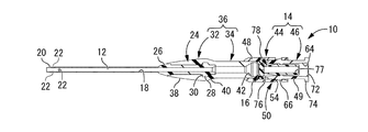
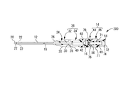
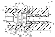
- FIG. 1 The perspective view which shows the needle
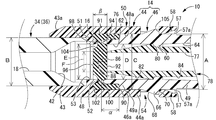
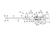
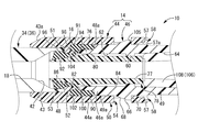
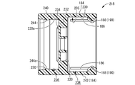
- the longitudinal cross-sectional perspective view which shows a specific example of the indwelling needle assembly comprised including the needle assembly with a valve which concerns on this invention. Sectional drawing which expands and shows the principal part in FIG. In the indwelling needle assembly shown in FIG.
- FIG. 12 is a longitudinal sectional view of the connector shown in FIG. 11. In the indwelling needle assembly shown in FIG.
- FIGS. 1 to 3 show a valve-attached needle assembly 10 as one embodiment of the present invention.
- the needle assembly with valve 10 includes a hollow needle 12 and a connection hub 14 to which an external flow path is connected on the proximal end side of the hollow needle 12.
- the disc valve 16 is accommodated and arranged.
- a fluid flow path 18 is formed from the blood vessel to the external flow path including the inside of the hollow needle 12 and the connection hub 14.
- the axial direction is the central axis direction of each member, substantially corresponds to the needle axis direction of the hollow needle 12, and refers to the left-right direction in FIG.
- the distal end side and the distal end side refer to the left side in FIG. 2 which is the side where the hollow needle 12 is punctured, while the proximal end side and the proximal end side are sides operated by the user.
- the hollow needle 12 is formed of a soft synthetic resin in the present embodiment, and the outer peripheral surface of the distal end portion is formed with a tapered outer peripheral surface 20 whose outer diameter dimension gradually decreases toward the distal end side. Has been.
- a plurality of through holes 22 are formed in the peripheral wall of the distal end portion of the hollow needle 12 so that blood or the like can easily flow into the hollow needle 12 through the through hole 22.
- a fixing portion 24 having a larger diameter than other portions is formed at the proximal end portion of the hollow needle 12. That is, the distal end portion and the proximal end portion of the fixing portion 24 are provided with an annular distal end large diameter portion 26 and a proximal end large diameter portion 28 whose outer diameters are increased. And between the axial direction of these front end side and base end side large diameter parts 26 and 28, the annular recessed part 30 made into the diameter smaller than the said front end side and base end side large diameter parts 26 and 28 is formed.
- the annular recess 30 is continuously formed over the entire circumference in the circumferential direction and has a predetermined axial dimension.
- the proximal end portion of the hollow needle 12 is fixedly supported by the needle hub 32.
- the needle hub 32 may be formed integrally with a tube 34 provided on the proximal end side of the needle hub 32, that is, the distal end side of an elastic tube 36 formed of a soft synthetic resin is used as the needle hub 32.
- the base end side of the elastic tube 36 may be configured as the tube 34.
- the elastic tube 36 has a substantially cylindrical shape extending in the axial direction with a substantially constant inner diameter and outer diameter in a single product state before the hollow needle 12 is fixed.
- the inner diameter in the single product state is the hollow needle 12.
- the outer diameter of the fixed portion 24 is smaller than the outer diameter.
- the proximal end portion of the hollow needle 12 is press-fitted from the opening on the distal end side of the elastic tube 36 and subjected to a treatment such as adhesion or welding as necessary, whereby the hollow needle 12 is moved by the elastic tube 36. Fixedly supported. That is, the distal end portion of the elastic tube 36 enters the annular recess 30 in the fixing portion 24 of the hollow needle 12, and the distal end portion of the elastic tube 36 constitutes the needle hub 32.
- the portion of the hollow needle 12 located on the outer periphery of the proximal end large diameter portion 28 is bulged and deformed toward the outer periphery, and the outer peripheral surface of the needle hub 32 extends from the distal end side to the proximal end side.
- a tapered outer peripheral surface 38 whose outer diameter dimension gradually increases toward the end.
- the outer peripheral surface from the proximal end of the needle hub 32 to the distal end of the tube 34 is an inverted tapered outer peripheral surface 40 whose outer diameter dimension gradually decreases from the distal end side toward the proximal end side.
- the elastic tube 36 is formed of a soft synthetic resin, and the outer peripheral surface thereof is formed of a smooth curved surface, so that the valve-attached needle assembly 10 is wound around, for example, the elastic tube 36 with a tape.
- the possibility that the patient feels pain due to the elastic tube 36 being in contact with the skin strongly or for a long time when being fixed on the skin is reduced.
- a taper surface 42 whose inner diameter dimension gradually increases toward the base end side is provided at the base end portion on the inner peripheral surface of the tube 34.
- the proximal end portion of the elastic tube 36 is fixed to the distal end portion of the connection hub 14.
- the connection hub 14 has a generally cylindrical shape as a whole, and the proximal end portion of the elastic tube 36 is inserted from the opening on the distal end side of the connection hub 14 and is subjected to bonding or welding as necessary. Thereby, the elastic tube 36 and the connection hub 14 are connected. That is, the distal end portion of the connection hub 14 is a tube connection portion 43 to which the elastic tube 36 is connected.
- the outer peripheral surface of the distal end portion of the tube connecting portion 43 is a tapered surface 43a that gradually decreases in outer diameter as it becomes the distal end side, for example, when the valve-attached needle assembly 10 is fixed on the patient's skin. In addition, the risk that the patient may feel pain when the corners touch the patient's skin is reduced.
- the fluid flow path 18 is configured by the respective inner holes of the hollow needle 12, the elastic tube 36 (particularly the tube 34), and the connection hub 14 (particularly a pusher 78 described later provided inside the connection hub 14). Yes.
- the connection hub 14 has a shape in which a connector cover 44 as a tubular body having a substantially cylindrical shape and a guide connector 46 as a connector are connected and fixed to each other in the axial direction. That is, the connector cover 44 is fixed to the distal end portion of the guide connector 46 by inserting and assembling the distal end side of the guide connector 46 into the proximal end side of the connector cover 44, and the connection hub 14 is configured.
- the peripheral wall 14 includes a peripheral wall 48 of the connector cover 44 and a peripheral wall 49 of the guide connector 46. Therefore, the distal end portion of the connector cover 44 is the tube connecting portion 43 described above.
- the distal end side of the guide connector 46 inserted into the connector cover 44 is a substantially cylindrical insertion portion 46a.
- the base end side of the connector cover 44 into which the insertion portion 46a of the guide connector 46 is inserted is a substantially cylindrical inserted portion 44a.
- the proximal end of the guide connector 46 extends to the proximal end side with a predetermined axial dimension from the connector cover 44. Therefore, the peripheral wall of the connection hub 14 has an assembly portion 50 having a double wall structure in which the inserted portion 44a and the insertion portion 46a are inserted and removed from each other at the connecting portion between the connector cover 44 and the guide connector 46.
- the peripheral wall on the distal end side of the connection hub 14 is constituted by the peripheral wall 48 of the connector cover 44
- the peripheral wall on the proximal end side of the connection hub 14 is constituted by the peripheral wall 49 of the guide connector 46.
- the inner peripheral surface 48 a of the peripheral wall 48 of the connector cover 44 and the peripheral wall 49 of the guide connector 46 is an overlapping surface of the connector cover 44 and the guide connector 46.
- the connector cover 44 is made of hard synthetic resin and includes a cylindrical peripheral wall 48.
- the peripheral wall 48 has an inner diameter dimension and an outer diameter dimension that are substantially constant over substantially the entire length in the axial direction.
- an annular wall 51 is formed on the inner peripheral surface of the peripheral portion 48 in the axial direction so as to protrude toward the inner peripheral side.
- the annular support part 52 which protrudes toward the base end side is provided in the inner peripheral side edge part of this annular wall part 51.
- the said annular support part 52 is made into the cross-sectional shape which becomes taper gradually toward the protrusion front end side (base end side).
- the inner peripheral surface of the annular support portion 52 is configured by a curved convex surface 53 that is convex toward the inner peripheral side.
- a pair of engagement holes 54 opened to the inner peripheral side are formed on both sides in the radial direction 1 (upper and lower sides in FIG. 2).
- 54 is formed, and in the present embodiment, these engagement holes 54, 54 are formed so as to penetrate in the thickness direction of the peripheral wall 48.
- Each of the engagement holes 54 and 54 has a substantially rectangular shape in plan view, and is partially formed on the circumference with a circumferential dimension less than a half circumference.
- the pair of engagement holes 54, 54 are positioned in the circumferential direction so as to be axially inward (front end side) from the opening edge of the axial end portion (base end side).
- a notch 56 extending toward the top is formed.
- a pair of notches 56 and 56 are formed with a predetermined width dimension on both sides in the direction orthogonal to the opposing direction of the pair of engagement holes 54 and 54 (both sides in the front and back direction in FIG. 2). ing.
- a pair of inclined guide surfaces 57, 57 are provided in the same direction as the engagement holes 54, 54 (both in the vertical direction in FIG. 2). Is formed, and the thickness dimension of the peripheral wall 48 gradually decreases toward the base end side. That is, on the inner peripheral surface 48a of the connector cover 44, the inclined guide surfaces 57, 57 gradually expand toward the proximal end, that is, toward the distal end in the assembly direction described later.
- the inclined guide surfaces 57, 57 and the both side wall portions 57a, 57a sandwiching the inclined guide surfaces 57, 57 the proximal end of the inner peripheral surface 48a of the peripheral wall 48 of the connector cover 44 is on the inner peripheral side.
- a pair of opening guide grooves 58, 58 are formed.
- the bottom surfaces of the guide grooves 58 and 58 are inclined guide surfaces 57 and 57, respectively.
- the guide connector 46 is formed of a hard synthetic resin and includes a peripheral wall 49 having a smaller diameter than the peripheral wall 48 of the connector cover 44.
- the peripheral wall 49 has an inner diameter dimension and an outer diameter dimension that are substantially constant over substantially the entire length in the axial direction.
- the outer diameter A (see FIG. 3) of the peripheral wall 49 is larger than the outer diameter B (see FIG. 3) of the tube 34, and the inner diameter C (see FIG. 3) of the peripheral wall 48 of the connector cover 44. 3).
- the inner diameter dimension D (see FIG. 3) of the peripheral wall 49 is substantially equal to the minimum inner diameter dimension E (see FIG. 3) of the curved convex surface 53 in the annular support portion 52 of the connector cover 44.
- An annular engagement wall 60 is formed on the inner peripheral surface of the peripheral wall 49 in the axially intermediate portion so as to protrude toward the inner peripheral side.
- the inner peripheral surface on the tip side of the engagement wall portion 60 is a guide surface 62 that guides the axial movement of a pusher 78 described later, and the inner diameter dimension is substantially constant.
- the inner peripheral surface on the base end side with respect to the engagement wall portion 60 is a tapered surface 64 whose inner diameter dimension gradually increases toward the base end side.
- a pair of locking protrusions 66 and 66 are formed to protrude on both sides in one radial direction (upper and lower sides in FIG. 2) in the axial intermediate portion of the outer peripheral surface 49a of the peripheral wall 49.
- the shape of these locking projections 66, 66 in plan view is a substantially rectangular shape corresponding to the engagement holes 54, 54 in the connector cover 44, and is partially formed on the circumference.
- the front end side end surfaces of the locking projections 66, 66 gradually decrease the protruding height of the locking projections 66, 66 toward the distal end side, that is, the locking projection 66 from the front to the rear in the insertion direction described later.
- 66 are inclined surfaces 68, 68 in which the projecting dimensions are gradually increased, and the base end side end surfaces are vertical surfaces 70, 70 extending in a direction substantially perpendicular to the axis.
- the inclination direction with respect to the axial direction of the inclined surfaces 68 and 68 in the locking projections 66 and 66 is equal to the inclination direction with respect to the axial direction of the inclined guide surfaces 57 and 57 in the guide grooves 58 and 58.
- the inclination angles of the both surfaces 57 and 68 with respect to the axial direction are also substantially equal, and the inclined surface 68 and the inclined guide surface 57 are substantially parallel to each other in the axial direction.
- a pair of positioning projections 71, 71 having a shape corresponding to 56 is formed to protrude.
- connection protrusion 74 protruding to the outer peripheral side is formed.
- a thread is formed on the outer peripheral surface of the connection protrusion 74, and it becomes possible to connect a luer lock type external flow path when the external flow path described later is connected.
- a cylindrical support cylinder portion 76 protruding to the front end side is provided on the front end surface of the peripheral wall 49.
- the inner diameter dimension of the support cylinder portion 76 is substantially equal to the inner diameter dimension of the peripheral wall 49, while the outer diameter dimension of the support cylinder portion 76 is smaller than the outer diameter dimension of the peripheral wall 49.
- the support cylinder part 76 is made into the cross-sectional shape which becomes taper gradually toward the front end side.
- a cylindrical pusher 78 having an inner hole 77 penetrating in the axial direction at the center is accommodated on the inner peripheral side of the guide connector 46 having such a shape. That is, the inner hole of the guide connector 46 includes the inner hole 77 of the pusher 78.
- the inner diameter of the pusher 78 is substantially constant over substantially the entire length in the axial direction.
- an annular step surface 80 extending in the direction perpendicular to the axis is formed on the outer peripheral surface on the distal end side with respect to the stepped surface 80 is a tapered outer peripheral surface 82 that gradually becomes smaller in diameter toward the distal end side, while the outer peripheral surface on the proximal end side with respect to the stepped surface 80 is substantially constant.
- the straight outer peripheral surface 84 made into the outer-diameter dimension.
- the maximum outer diameter of the proximal end portion of the tapered outer peripheral surface 82 is larger than the outer diameter of the straight outer peripheral surface 84.
- the minimum outer diameter dimension F at the distal end portion of the tapered outer peripheral surface 82 is smaller than the outer diameter dimension of the straight outer peripheral surface 84 and the minimum inner diameter of the curved convex surface 53 in the annular support portion 52 of the connector cover 44. It is made smaller than the dimension E.
- the disk valve 16 is accommodated on the inner peripheral side of the connector cover 44.
- the disc valve 16 has a substantially disk shape and is formed of a material having elasticity such as rubber or elastomer.
- a slit 88 penetrating in the axial direction is formed in the central portion 86 of the disc valve 16.
- the shape of the slit 88 is not limited, in the present embodiment, the slit 88 has a radial shape extending substantially uniformly in three directions in the circumferential direction.
- the disk valve 16 In the single-piece state of the needle assembly with valve 10 to which the external flow path is not connected, the disk valve 16 is supported by being applied with a radial pressing force from the outer peripheral side toward the inner peripheral side, for example.
- the slit 88 is closed.
- a cylindrical support portion 90 extending toward the proximal end is provided on the outer peripheral portion of the disc valve 16.
- the outer diameter of the disc valve 16 and the outer diameter of the cylindrical support portion 90 are substantially equal, and the outer peripheral surface 91 of the disc valve 16 and the outer peripheral surface of the cylindrical support portion 90 An annular surface that is flat in the axial direction is formed.
- the base end side that continuously extends over the entire circumference in the circumferential direction and opens to the base end side from the cylindrical support portion 90.
- a concave groove 94 is formed in the outer peripheral portion of the base end side surface 92 of the disc valve 16.
- the outer peripheral portion of the distal end side surface 96 of the disc valve 16 is formed with a distal end side concave groove 98 that continuously extends over the entire circumference and opens to the distal end side.
- the base end side concave groove 94 and the front end side concave groove 98 are formed at substantially the same position in the radial direction of the disc valve 16, and the base end side concave groove 94 and the front end side concave groove 98 are formed.
- the space between the bottom surfaces is a constricted portion 100 having a thickness dimension (axial dimension) smaller than that of the central portion 86.
- the thickness dimension (axial dimension) in the constricted part 100 is smaller than the thickness dimension (axial perpendicular dimension) in the cylindrical support part 90.
- the outer peripheral side of the constricted portion 100 protrudes to the base end side and the tip end side from the bottom surfaces of the base end side concave groove 94 and the front end side concave groove 98, and protrudes to the base end side.
- the portion is the above-described cylindrical support portion 90
- the portion protruding toward the distal end is the distal tubular portion 102.
- the distal end surface of the distal cylindrical portion 102 is at substantially the same axial position as the distal end side surface 96 of the disc valve 16, and the proximal end surface of the cylindrical support portion 90 is the proximal end side surface 92 of the disc valve 16. It is located on the base end side.
- the central portion 86 in which the slit 88 is formed is located in the inner peripheral portion surrounded by the constricted portion 100.
- the axial length ⁇ (see FIG. 3) of the cylindrical support portion 90 is half of the thickness dimension (axial length) ⁇ (see FIG. 3) at the central portion 86 of the disc valve 16. This is the case ( ⁇ ⁇ ⁇ / 2). With such dimensions, the effect of preventing the disk valve 16 from falling off and the effect of supporting the guide connector 46, which will be described later, can be stably exhibited.
- a circumferential groove 104 is formed on the inner peripheral side of the distal end side concave groove 98 adjacent to the distal end side concave groove 98 and continuously extending over the entire circumference in the circumferential direction.
- the inner surface of the tip side concave groove 98 and the inner surface of the circumferential groove 104 are continuous with each other in the radial direction.
- the inner surface of the circumferential groove 104 and the curved convex surface 53 of the annular support portion 52 of the connector cover 44 are spaced apart from each other in the radial direction to form a gap.
- connection hub 14 is constituted by the connector cover 44, the guide connector 46, the disc valve 16 and the pusher 78 having the above-described structure.
- the pusher 78 is inserted from the distal end side opening of the guide connector 46 and disposed.
- the base end position of the pusher 78 is such that the engaging wall portion 60 provided on the inner peripheral surface of the guide connector 46 and the step surface 80 provided on the outer peripheral surface of the pusher 78 abut each other. It is prescribed by.
- the straight outer peripheral surface 84 of the pusher 78 and the inner peripheral surface of the engagement wall portion 60 are in contact with or slightly separated from each other, and the tapered shape of the pusher 78 is also provided.
- the outer peripheral surface at the proximal end portion of the outer peripheral surface 82 and the guide surface 62 of the guide connector 46 are in contact with each other or slightly separated from each other. Accordingly, the pusher 78 is movable in the axial direction while being guided by the inner peripheral surface of the guide connector 46.
- the cylindrical support portion 90 of the disc valve 16 is covered and supported at the tip portion of the guide connector 46. That is, the distal end portion of the support cylindrical portion 76 provided at the distal end of the guide connector 46 is located in the proximal end side recessed groove 94 of the disc valve 16. Thus, the distal end portion of the support cylinder portion 76 is inserted. At the same time, the inner peripheral surface of the cylindrical support portion 90 of the disc valve 16 is in contact with the outer peripheral surface of the support cylindrical portion 76, and the distal end portion of the guide connector 46 is fitted to the proximal end side of the disc valve 16. ing.
- the inner and outer peripheral surfaces of the distal end portion of the support cylinder portion 76 are in contact with the inner and outer peripheral surfaces constituting the inner surface of the proximal end side recessed groove 94. Further, a gap is formed between the distal end surface of the support cylinder portion 76 and the bottom surface of the proximal end side recessed groove 94 so that the disk valve 16 can be easily elastically deformed when the pusher 78 described later is moved. The improvement and the durability of the disc valve 16 are improved.
- the distal end of the pusher 78 is in contact with the proximal side surface 92 of the disc valve 16, and the pusher 78 is in the axial direction of the disc valve 16 and the engaging wall portion 60. Are positioned between.
- the connector cover 44 is assembled from the front end side of the disc valve 16. That is, the tip end portion of the guide connector 46 is inserted from the proximal end side opening of the connector cover 44 with the disc valve 16 being covered at the tip end, and the locking projections 66, 66 of the guide connector 46 are inserted into the connector cover 44. By engaging with the engaging holes 54, 54, the connector cover 44 and the guide connector 46 are connected in series in the axial direction on the same central axis.
- the vertical surfaces 70, 70 that are the base end side end surfaces of the locking projections 66, 66 abut on the base end side inner surfaces 105, 105 of the engagement holes 54, 54, so that the insertion portion 44 a of the connector cover 44
- the insertion portion 46a of the guide connector 46 is prevented from being pulled out. Therefore, the base end side inner surfaces 105, 105 of the engagement holes 54, 54 constitute a locking portion for locking the locking projections 66, 66.
- the engaging portions base end side inner surfaces 105, 105) overlap with the guide grooves 58, 58 on the axial extension line on the inner peripheral surface 48 a of the peripheral wall 48 of the connector cover 44.
- guide grooves 58, 58 (inclined guide surfaces 57, 57), that is, on the rear side in the assembly direction of the connector cover 44 described later.
- the direction from the distal end side to the proximal end side is an assembly direction as will be described later.
- Guide grooves 58 and 58 (inclined guide surfaces 57 and 57) are provided at the distal end portion (axial base end portion) in the assembly direction. That is, the guide grooves 58, 58 extend from the distal end portion in the assembly direction of the connector cover 44 toward the locking portion (base end side inner surfaces 105, 105).
- the assembly of the connector cover 44 and the guide connector 46 is realized by inserting the guide connector 46 into the connector cover 44. That is, the direction in which the connector cover 44 and the guide connector 46 approach each other is the assembly direction. In the connector cover 44, the direction from the distal end side to the proximal end side is the assembly direction. The direction from the proximal end side to the distal end side is the assembly direction. In the present embodiment, since the guide connector 46 is inserted into the connector cover 44, the assembly direction of the guide connector 46 (the direction from the proximal end side to the distal end side) among the assembly directions is particularly the insertion direction. Has been.
- the insertion direction is not limited to this, and a tubular body (outer needle cap 216, connector cover 292) located on the distal end side as in a second embodiment to be described later or an aspect shown in FIG. May be inserted into a connector (cap connector 218, guide connector 294) located on the proximal end side.
- the assembling direction in the tube body is the insertion direction, and the direction from the distal end side toward the proximal end side It is said.
- the locking projections 66, 66 of the guide connector 46 are inserted into the guide grooves 58, 58 of the connector cover 44, and the notches 56, 56 of the connector cover 44 are inserted.
- the positioning projections 71 and 71 of the guide connector 46 By inserting the positioning projections 71 and 71 of the guide connector 46, the locking projections 66 and 66 and the engagement holes 54 and 54 can be easily positioned in the circumferential direction.
- the inclined guide surfaces 57 and 57 that are the groove bottom surfaces of the guide grooves 58 and 58 and the inclined surfaces 68 and 68 of the locking protrusions 66 and 66 are brought into contact with each other, so that the locking protrusions 66 and 66 become the guide groove. It is easy to be guided by the inclined guide surfaces 57, 57 of the 58, 58 and to be engaged with the engagement holes 54, 54 located on the tip side of the guide grooves 58, 58.
- the outer peripheral portion of the disc valve 16 is positioned and held in the axial direction and the direction perpendicular to the axis between the connector cover 44 and the guide connector 46 assembled to each other.
- the connector cover 44 and the guide connector 46 are assembled in a fitted state.
- the protruding front end portion of the annular support portion 52 in the connector cover 44 is located in the front end side concave groove 98 of the disc valve 16.
- the protruding front end portion of the annular support portion 52 is the front end side concave groove 98. Has been inserted against.
- the inner and outer peripheral surfaces of the distal cylindrical portion 102 of the disc valve 16 are in contact with the outer peripheral surface of the annular support portion 52 and the inner peripheral surface of the peripheral wall 48 of the connector cover 44. That is, the annular support portion 52 of the connector cover 44 is fitted to the distal end side of the disc valve 16, and the distal end side tubular portion 102 of the disc valve 16 is covered with the outer peripheral surface of the annular support portion 52. It is supported.
- the distal end side cylindrical portion 102 is pressed and sandwiched between the outer peripheral surface of the annular support portion 52 and the inner peripheral surface 48 a of the peripheral wall 48 of the connector cover 44.
- the inner and outer peripheral surfaces of the annular support portion 52 are in contact with the inner and outer peripheral surfaces constituting the inner surface of the tip side concave groove 98.
- the outer peripheral surface 91 of the disc valve 16 and the outer peripheral surface of the cylindrical support portion 90 are in contact with the inner peripheral surface 48 a of the peripheral wall 48 of the connector cover 44.
- the outer diameter of the disc valve 16 is slightly larger than the inner diameter of the connector cover 44, and the disc valve 16 is interposed between the connector cover 44 and the guide connector 46.
- the outer peripheral surface 91 of the disc valve 16 is pressed to the inner peripheral side (axial center direction) by the inner peripheral surface 48a of the peripheral wall 48 of the connector cover 44. That is, the inner peripheral surface 48 a of the peripheral wall 48 of the connector cover 44 constitutes a pressing portion that presses the disk valve 16 toward the inner peripheral side.
- the pressing portion (the inner peripheral surface 48a of the peripheral wall 48) is a flat annular surface.
- the thickness dimension of the cylindrical support portion 90 (dimension in the direction perpendicular to the axis) is slightly smaller than the radial distance between the support cylindrical portion 76 of the guide connector 46 and the peripheral wall 48 of the connector cover 44.
- the cylindrical support part 90 is sandwiched and pressed between the support cylinder part 76 and the peripheral wall 48 of the connector cover 44 in the thickness direction (radial direction).
- the outer peripheral portion of the disc valve 16 may be sandwiched between the axial direction by the connector cover 44 and the guide connector 46 in a compressed state.
- the assembly of the connector cover 44, the guide connector 46, the disc valve 16 and the pusher 78 is assembled with the tip end facing upward, so that the disc valve 16 can be removed from the guide connector 46 during assembly.
- the assembling method is not limited to this.
- the needle assembly 10 with a valve By connecting the hollow needle 12, the elastic tube 36 and the connection hub 14 in the axial direction as described above, the needle assembly 10 with a valve according to this embodiment is configured.
- an inner needle unit (not shown) configured to include an inner needle having a needle tip is inserted into an outer needle unit configured to include the needle assembly with valve 10. Therefore, it is used as an indwelling needle assembly with a valve. That is, the valve-attached needle assembly 10 is placed in the patient's blood vessel by puncturing the patient's blood vessel with the valve and withdrawing the inner needle unit from the outer needle unit.
- the specific structure of the inner needle unit is not limited in any way, but specific examples of the indwelling needle assembly are shown in FIGS. 6 to 13 described later.
- the hollow needle 12 is a needle made of metal or the like having a needle tip, the valved needle assembly 10 can be directly punctured and placed in the blood vessel of the patient.
- a syringe 106 as an external flow path is inserted and connected from the proximal end side of the valve-attached needle assembly 10 placed in the patient's blood vessel, so that the patient's blood vessel is obtained. And an external flow path (syringe) 106 are communicated with each other via a fluid flow path 18.
- the male luer 108 of the syringe 106 is inserted from the proximal end side opening 72 of the connection hub 14 (guide connector 46), so that the pusher accommodated inside the guide connector 46 by the distal end of the male luer 108. 78 is moved to the tip side. As a result, the tip of the pusher 78 is pressed against the base end side surface 92 of the disc valve 16, and the disc valve 16 is elastically deformed to open the slit 88 of the disc valve 16.
- the disc valve 16 is elastically deformed as shown in FIG. That is, it is elastically deformed by the tip of the pusher 78 so that the inner peripheral side (central portion 86) is pulled toward the tip side from the constricted part 100.
- the inner surface of the circumferential groove 104 provided on the distal end side surface 96 of the disc valve 16 comes into contact with substantially the entire curved convex surface 53 of the annular support portion 52 provided on the connector cover 44. Yes.
- blood can be effectively prevented from entering between the disc valve 16 and the connector cover 44.
- the elastic restoring force of the disc valve 16 can be exerted more greatly.
- the distal end side surface 96 of the central portion 86 of the disc valve 16 comes into contact with the inner peripheral surface of the proximal end side opening of the elastic tube 36.
- the fluid flow path 18 is in a communicating state, so that infusion or blood collection can be performed through the fluid flow path 18.
- the syringe 106 is removed from the connection hub 14 (guide connector 46), so that the disk valve 16 has its shape before connection of the syringe 106 due to its own elastic restoring action (see FIG. 3), the slit 88 is closed (the fluid flow path 18 is blocked).
- the pusher 78 is pushed back to the proximal end side by the central portion 86 of the disc valve 16 and moved, and the stepped surface 80 of the pusher 78 is at the moving end of the pusher 78 toward the proximal end side. It is defined by abutting against an engaging wall portion 60 provided on the inner peripheral surface of the guide connector 46. Accordingly, the pusher 78 can be positioned at a predetermined position when the external flow path (syringe) 106 is removed.
- one of the connector cover 44 and the guide connector 46 is inserted into the other, and the engagement holes 54 provided in the peripheral wall 48 of the connector cover 44,
- the locking projections 66 and 66 provided on the guide connector 46 are locked with respect to 54, the connector cover 44 and the guide connector 46 are assembled to each other to form the connection hub 14. That is, since no adhesive or the like is used when assembling the connector cover 44 and the guide connector 46, the adhesive does not leak into the fluid flow path 18, and the bonding process is omitted. Therefore, the manufacturing efficiency of the connection hub 14 and, consequently, the valved needle assembly 10 can be improved.
- guide grooves 58 and 58 are provided on the proximal end sides of the engagement holes 54 and 54, and the locking protrusions 66 and 66 are inserted into the guide grooves 58 and 58 by inserting the locking protrusions 66 and 66. Since the engagement holes 54 and 54 are more reliably guided, the connector cover 44 and the guide connector 46 are not only positioned in the circumferential direction, but the connector cover 44 and the guide connector 46 are smoothly moved. As a result, the manufacturing efficiency of the valved needle assembly 10 can be further improved.
- the connector cover 44 is provided with notches 56 and 56, while the guide connector 46 is provided with positioning protrusions 71 and 71, and the positioning protrusions 71 and 71 are inserted into the notches 56 and 56.
- the circumferential positions of the connector cover 44 and the guide connector 46 can be effectively positioned. Therefore, the engagement between the engagement holes 54 and 54 and the locking projections 66 and 66 as described above can be realized stably.
- the peripheral wall 48 at the base end portion of the connector cover 44 is provided with the notches 56, 56, the peripheral wall 48 of the connector cover 44 is easily bent when the guide connector 46 is inserted into the connector cover 44. The assembly of the cover 44 and the guide connector 46 can be realized even more easily.
- a separate coil spring or the like is not used for closing and deforming the disk valve, so that the insertion resistance of the syringe 106 can be reduced and the number of parts can be reduced. Further, an increase in the number of assembly steps can be suppressed, and an increase in the size of the valve-attached needle assembly 10 can be avoided.
- the central portion 86 of the disk valve 16 is pulled toward the distal end side and is elastically deformed. Since the cylindrical support portion 90 extending to the base end side is provided on the outer peripheral portion, the disk valve 16 can be effectively prevented from falling off from the connection hub 14. In particular, since the cylindrical support portion 90 is sandwiched in a pressed state between the support cylinder portion 76 in the guide connector 46 and the peripheral wall 48 of the connector cover 44, the disk valve 16 from the connection hub 14 is held. Dropout can be more effectively prevented.
- the support force of the disc valve 16 is exhibited especially by the cylindrical support portion 90, for example, the radial compressive force by the connection hub 14 and the like compared to the case where the disc valve is a simple flat plate, for example. Can be made small or substantially zero.
- the central portion 86 of the disc valve 16 can be easily elastically deformed, and the insertion resistance of the external flow path (syringe) 106 is reduced.
- the cylindrical support portion 90 provided at the outer peripheral edge portion of the disc valve 16 is sandwiched between the support cylinder portion 76 and the peripheral wall 48, the disc valve 16 can be externally moved even when pressed by the pusher 78. By suppressing the elastic deformation of the peripheral portion, the elastic restoring force to the initial shape of the disc valve 16 when the syringe 106 is removed can be exhibited more advantageously.
- connection hub 14 is configured to include a guide connector 46 that guides the axial movement of the pusher 78.
- a member that guides the pusher 78 is separated from the connection hub 14, and the connection hub 14 has a separate member.
- the outer diameter of the disc valve 16 that covers the guide connector 46 and, consequently, the distal end portion of the guide connector 46 can be ensured.
- a sufficient rubber volume of the disc valve 16 can be ensured.
- durability and reliability can be improved, and the opening of the slit 88 can be increased. 16 is easily elastically deformed.
- a distal end side groove 96 and a proximal end side groove 94 are provided on the distal end side surface 96 and the proximal end side surface 92 of the disc valve 16, respectively, and the annular support portion of the connector cover 44 is provided in these recessed grooves 98, 94. 52 and the support cylinder portion 76 of the guide connector 46 are inserted, the holding force of the disc valve 16 by the connection hub 14 can be stably improved. Further, the distance between the opposed portions in the axial direction of the annular support portion 52 and the support cylindrical portion 76 is made smaller than the plate thickness dimension of the cylindrical support portion 90, so that the space between the annular support portion 52 and the support cylindrical portion 76 is reduced. Since the cylindrical support portion 90 is effectively prevented from falling out of the disk hub 16, it is possible to more effectively prevent the disc valve 16 from falling off the connection hub 14.
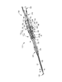
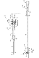
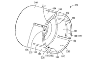
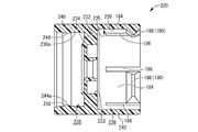
- FIGS. 6 and 7 show a specific example of the indwelling needle assembly according to the present invention.
- substantially the same members and parts as the valved needle assembly 10 shown in FIGS. 1 to 5 are given the same reference numerals as those in FIGS. Detailed description is omitted.
- the indwelling needle assembly 110 shown in FIGS. 6 and 7 is configured to extend in the needle axis direction along the predetermined axis L1, and includes an inner needle unit 114 including the protector 112.
- the outer needle unit 116 and a connection cap 118 that connects the inner needle unit 114 and the outer needle unit 116 are provided.
- the outer needle unit 116 according to the present embodiment includes a valve-attached needle assembly 119 and a connection cap 118 that have substantially the same structure as the valve-attached needle assembly 10 shown in FIGS. Has been.
- valve-attached needle assembly 119 in the indwelling needle assembly 110 is different from the valve-attached needle assembly 10 shown in FIGS. 1 to 5, and is a tube connected to the needle hub and the proximal end side of the needle hub.
- the hollow needle 12 as an outer needle is fixedly supported on an outer needle hub 120 made of a hard synthetic resin, and from a soft synthetic resin from the base end side of the outer needle hub 120.
- the resulting tube 122 extends.
- the outer needle hub 120 includes a substantially cylindrical peripheral wall 124, and the hollow needle 12 is inserted through the distal end side opening of the peripheral wall 124 and is fixed to the inner peripheral surface of the peripheral wall 124.
- the distal end of the tube 122 is sandwiched between the hollow needle 12 and the peripheral wall 124 at the proximal end side opening of the outer needle hub 120, and an adhesion or welding process is performed as necessary, so that the outer needle hub A tube 122 is connected to the proximal end opening of 120.
- the inner needle unit 114 includes an inner needle 126, an inner needle hub 128, and an inner needle cap 130.
- the inner needle 126 is a generally cylindrical hollow needle made of, for example, a metal material or a hard synthetic resin, and extends straight along the axis L1.
- the inner needle 126 has a sharp needle tip 132 at its distal end, and the needle tip 132 is sharply formed so as to be able to puncture a blood vessel.
- two protrusions 134 and 134 are formed near the needle tip 132.
- the two protrusions 134 and 134 protrude from the outer peripheral surface of the inner needle 126 radially outward and in opposite directions. In addition, this protrusion part 134 may be provided over the perimeter of the circumferential direction.
- the inner needle 126 may be a solid needle.
- An inner needle hub 128 is provided at the proximal end of the inner needle 126.
- the inner needle hub 128 is formed in a substantially cylindrical shape, and its intermediate portion is narrowed compared to the proximal portion and the distal portion. Further, the proximal end side portion of the inner needle 126 is fitted into the inner hole of the intermediate portion and is fixed by an adhesive or the like. Further, a distal opening and a proximal opening are formed at the distal end and the proximal end of the inner needle hub 128, respectively, and at the center of the bottom wall of the distal opening, a distal side is formed. A protruding ceiling 136 is formed. On the other hand, an inner needle cap 130 is fitted into the proximal opening of the inner needle hub 128, and the proximal opening is closed by the inner needle cap 130.
- the distal portion of the inner needle hub 128 is formed with a larger diameter than the remaining portions (ie, the intermediate portion and the proximal portion), and within the distal portion of the inner needle hub 128 A part of each of the luer cap 164 and the protector 112, which will be described in detail later, is accommodated.
- the inner needle 126 of the inner needle unit 114 configured as described above is inserted through the outer needle unit 116.
- a ventilation filter (not shown) is provided inside the inner needle cap 130, and the ventilation filter has a property of allowing gas to pass but blocking liquid.
- the protector 112 is for storing and protecting the needle tip 132 of the inner needle 126, and includes a casing 138 and a shutter mechanism 140.
- the casing 138 is a generally hollow cylindrical member made of synthetic resin.
- the casing 138 has a tapered portion 142 at an intermediate portion thereof, and the tapered portion 142 is formed in a tapered shape so as to gradually expand in diameter as it advances distally.
- the large diameter portion 144 including the tapered portion 142 is formed on the distal side, and the small diameter portion 146 is formed on the proximal side.
- An annular ring member 148 is provided at the proximal end in the casing 138.
- the distal side opening of the casing 138 (the distal side opening of the large-diameter portion 144) is closed by assembling a lid 150 having a substantially flat plate shape as a whole.
- the space surrounded by the large diameter portion 144 including the tapered portion 142 and the lid body 150 is defined as the accommodation space 151 by closing the distal opening of the large diameter portion 144 by the lid body 150. ing.
- the inner needle 126 is inserted into the casing 138 so as to be movable in the needle axis direction with the needle tip 132 protruding. That is, a proximal end insertion hole 152 is formed around the axis L 1 at the proximal end of the casing 138, and an intermediate insertion hole 154 and a distal insertion hole 156 are formed in the lid 150.
- the inner needle 126 is inserted through the insertion holes 152, 154, 156.
- the inner needle 126 is also inserted through the ring member 148.
- the two protrusions 134 and 134 in the inner needle 126 are configured to be able to be inserted through the intermediate insertion hole 154 and the distal end insertion hole 156 on the distal side, but engage with the ring member 148. It is configured as follows. Therefore, when the inner needle 126 is moved relative to the protector 112 (that is, the inner needle 126 is pulled out from the protector 112), the two protrusions 134 and 134 are connected to the distal intermediate insertion hole 154 and the tip. It fits in the protector 112 through the side insertion hole 156 and then engages with the ring member 148 so as to remain in the protector 112.
- the positions of the protrusions 134 and 134 are adjusted so that the needle tip 132 is accommodated in the protector 112 when the protrusions 134 and 134 are engaged with the ring member 148.
- the protector 112 in order to prevent the needle tip 132 contained therein from coming out of the protector 112, it is within the large diameter portion 144 and between the intermediate insertion hole portion 154 and the distal end side insertion hole portion 156.
- the shutter mechanism 140 is accommodated in the housing.
- the shutter mechanism 140 includes a shielding member 158 and a fixing member 160. That is, one of the shielding member 158 and the fixing member 160 is a magnet, and the other is a ferromagnetic material such as a magnet or iron, and a magnetic attractive force is exerted on each other.
- the shielding member 158 and the fixing member 160 are disposed to face each other in the radial direction.
- the fixing member 160 is fixed to the lid body 150, and the shielding member 158 is provided in the lid body 150 so as to be movable toward the fixing member 160, and the lid body 150 is provided in the casing 138.
- the shielding member 158 and the fixing member 160 are accommodated in the accommodating space 151 in the large-diameter portion 144 of the casing 138 by being fixed to the distal opening.
- the inner needle 126 is inserted between the shielding member 158 and the fixing member 160 in a state before use as shown in FIGS. 6 and 7, thereby the shielding member 158 and the fixing member 160. And are spaced apart.
- the inner needle 126 is pulled out proximally with respect to the protector 112 and the needle tip 132 is accommodated in the casing 138, the following operation is performed. That is, the shielding member 158 is sucked by the fixing member 160 and is attracted to the fixing member 160.
- the shielding member 158 is disposed on the axis L1 in the casing 138, that is, between the needle tip 132 and the distal end side insertion hole 156, and the needle tip 132 is positioned in the housing space 151, and the accommodation space The distal end side insertion hole 156 which is an opening on the distal end side of 151 is closed.
- the distal end side insertion hole 156 which is an opening on the distal end side of 151 is closed.
- the proximal end of the inner needle 126 having the above-described structure is inserted into the inner needle hub 128, and the inner needle 126 is fixedly supported on the inner needle hub 128 by being subjected to bonding or welding as necessary.
- the protector 112 is attached to the inner needle 126 so as to be movable in the axial direction, whereby the inner needle unit 114 of this embodiment is configured.
- the inner needle 126 protruding toward the distal end side in the inner needle unit 114 is the proximal end side opening of the needle assembly with valve 119, that is, the proximal end side of the guide connector 46.
- the needle tip 132 of the inner needle 126 protrudes from the distal end of the hollow needle 12. Yes. Thereby, the inner needle unit 114 and the needle assembly with valve 119 are assembled to each other.
- connection cap 118 is provided between the guide connector 46 of the valve-attached needle assembly 119 and the protector 112 of the inner needle unit 114, and the outer cap unit 116 and the inner needle unit 114 are connected by the connection cap 118.
- the connection cap 118 includes an outer needle cap 162 having a substantially cylindrical shape and a luer cap 164 as a cap body.
- the outer needle cap 162 is a substantially cylindrical member made of hard synthetic resin or the like.
- the outer needle cap 162 has a step 166 at an axially intermediate portion of its outer peripheral surface, and a distal side portion of the step 166 is formed with a smaller diameter than the proximal portion.
- the distal end portion of the outer needle cap 162 is inserted and screwed into the proximal end portion of the guide connector 46, and the outer needle cap 162 is proximal to the outer needle hub 120, in this embodiment.
- a proximal end portion of the guide connector 46 is detachably provided.
- an inward flange 168 is formed on the inner peripheral surface of the outer needle cap 162 at its axially intermediate portion (more specifically, a position substantially corresponding to the step 166).
- the inward flange 168 is formed on the entire inner circumferential surface of the outer needle cap 162 in the circumferential direction, and protrudes radially inward from the inner circumferential surface.
- an insertion cylindrical portion 170 is formed on the inner peripheral edge of the inward flange 168.
- the insertion cylindrical portion 170 is formed in a substantially cylindrical shape, and protrudes distally from the inner peripheral edge portion of the inward flange 168.
- the outer diameter of the insertion cylindrical portion 170 is substantially the same as the inner diameter of the guide connector 46, and the insertion cylindrical portion 170 is inserted into the guide connector 46 with the outer needle cap 162 screwed into the guide connector 46. It has come to be.
- the outer needle cap 162 opens to the proximal side on both sides in one direction in the radial direction (both sides in the vertical direction in FIGS. 6 and 7) and in the thickness direction (the radial direction).
- a pair of notches 172 and 172 penetrating therethrough are formed. These notches 172 and 172 are substantially rectangular in a plan view, and are formed with a predetermined circumferential dimension.
- the inner hole of the outer needle cap 162 is separated into a distal region 174 and a proximal region 176 by an inward flange 168.
- the proximal end portion of the guide connector 46 is inserted into the distal region 174.
- a part of the distal side of the luer cap 164 is inserted into the proximal region 176. That is, the outer needle cap 162 and the luer cap 164 are provided in series in the axial direction in the connection cap 118, and the most proximal portion of the outer needle unit 116 is constituted by the luer cap 164 as a cap body. ing.
- the luer cap 164 is a substantially cylindrical member made of hard synthetic resin or the like, and has a pushing portion 178 and a housing portion 180.
- the pushing portion 178 is formed to have a smaller diameter than the housing portion 180, and the outer diameter dimension thereof is substantially the same as the inner diameter dimension of the insertion cylindrical portion 170 of the outer needle cap 162.
- the pushing portion 178 is inserted through the insertion cylindrical portion 170, and the distal end of the pushing portion 178 is opposed to the proximal end of the pusher 78 provided in the guide connector 46.
- the pushing portion 178 arranged in this way is formed to be longer than the insertion cylindrical portion 170 in the needle axis direction, and a housing portion 180 is integrally provided on the proximal side portion of the pushing portion 178. .
- the accommodating portion 180 is formed in a generally bottomed cylindrical shape, and its outer diameter dimension is substantially the same as the hole diameter dimension of the proximal region 176 in the outer needle cap 162.
- the accommodating portion 180 having such a shape is inserted into the proximal region 176 and provided on the proximal side of the connection cap 118. More specifically, since the pushing portion 178 is formed longer than the insertion cylindrical portion 170, the accommodating portion 180 is provided on the proximal side with respect to the inward flange 168 (that is, at the reference position). It has been. Therefore, the luer cap 164 can be pushed further distally from this reference position, which pushes open the slit 88 of the disc valve 16 by the pusher 78 to bring the fluid flow path 18 into communication. Can do.
- a through hole 182 is formed around the central axis of the accommodating portion 180.
- the through hole 182 communicates with the inner hole of the push-in portion 178.
- the inner needle 126 is inserted into the through-hole 182 and the inner hole of the push-in portion 178 so as to be relatively movable in the needle axis direction, and the needle tip 132 is a hollow needle. 12 protrudes distally.
- the proximal end portion of the accommodating portion 180 protrudes from the proximal end of the outer needle cap 162 toward the proximal side.
- the distal end of the inner needle hub 128 faces the proximal end of the outer needle cap 162, and the proximal end portion of the accommodating portion 180 is inserted into the inner needle hub 128.
- the protector 112 is inserted into the housing portion 180 of the luer cap 164 configured as described above.
- the housing portion 180 of the luer cap 164 has a plurality of flexible pieces 184 and 184 (in this embodiment, a pair of flexible pieces 184 and 184), and each of the pair of flexible pieces 184 and 184 includes They are arranged at substantially equal intervals in the circumferential direction (that is, at intervals of about 180 degrees).
- a pair of flexible pieces 184 and 184 are formed on both sides in the radial direction 1 (both sides in the vertical direction in FIGS. 6 and 7) in the proximal opening of the housing portion 180.
- Each flexible piece 184 is formed by a pair of notched grooves 186 and 186, as shown in FIG. 7 and FIG.
- a pair of notch grooves 186 and 186 are formed on the outer peripheral surface of the accommodating portion 180 at intervals in the circumferential direction. Further, the pair of cutout grooves 186 and 186 penetrates the accommodating portion 180 in the radial direction, and extends from the proximal end of the accommodating portion 180 to the axially intermediate portion in the needle axis direction. The pair of notch grooves 186 and 186 are formed in this way, and as a result, a plate-like flexible piece 184 is formed between them.
- the flexible piece 184 formed in this manner can be bent outward in the radial direction, and the inner surface of the flexible piece 184 (that is, the inner surface of the housing portion 180) is convex.
- a shaped engagement portion 188 is formed. That is, the housing portion 180 of the luer cap 164 has a pair of convex engaging portions 188 and 188 on its inner peripheral portion, and the engaging portion 190 includes the pair of convex engaging portions 188 and 188. It is configured. Further, the pair of convex engaging portions 188 and 188 are arranged so as to face each other in the radial direction.
- the convex engagement portion 188 protrudes radially inward from the inner peripheral surface of the flexible piece 184, and extends from one end of the flexible piece 184 to the other end in the circumferential direction. Further, as shown in FIGS. 6 and 7, the convex engagement portion 188 is formed in a cross-sectional mountain shape as viewed by cutting along a virtual plane including the axis L1.
- the convex engaging portion 188 having such a shape corresponds to the tapered portion 142 of the casing 138 of the protector 112 in a state where the protector 112 is housed in the luer cap 164 (that is, the tapered portion of the casing 138). 142 radially outward).
- the convex engagement portion 188 can engage with the large diameter portion 144 (more specifically, the taper portion 142), and can hold the protector 112 and the luer cap 164 in a connected state.
- the engaged portion that engages with the engaging portion 190 is constituted by the large-diameter portion 144 including the tapered portion 142 provided on the outer peripheral portion of the casing 138.
- the protector 112 that fits in this manner projects the small diameter portion 146 of the casing 138 from the luer cap 164 into the inner needle hub 128, and the proximal side portion of the small diameter portion 146 of the casing 138 is the inner needle hub 128. Is housed inside.
- the proximal end of the casing 138 is applied to a ceiling 136 provided on the inner needle hub 128. Thereby, the protector 112 is clamped by the ceiling 136 and the bottom surface of the accommodating portion 180, and the movement of the protector 112 is restricted.
- the protector 112 can be pulled out of the luer cap 164 in the needle axis direction and moved.
- the convex engagement portion 188 has a mountain-shaped cross section, so that the large diameter portion 144 causes the convex engagement portion 188 to have a radius. Pushed outward in the direction. Accordingly, the pair of flexible pieces 184 and 184 bend radially outward, and the distance between the pair of convex engaging portions 188 and 188 can be increased. Thereby, the engagement between the pair of convex engaging portions 188 and 188 and the large diameter portion 144 is released, and the protector 112 can be detached from the luer cap 164 (that is, pulled out).
- the convex engagement portion 188 has a mountain shape in cross section, when the protector 112 is inserted into the luer cap 164, the convex engagement portion 188 is pushed radially outward by the large diameter portion 144 and a pair of The flexible pieces 184 and 184 are bent outward in the radial direction. As a result, the radial distance between the pair of convex engaging portions 188 and 188 is increased, and the protector 112 can be smoothly inserted into the luer cap 164.
- the luer cap 164 is inserted into the outer needle cap 162 as described above.
- notches 172 and 172 are formed on the outer peripheral surface of the outer needle cap 162 at positions corresponding to the pair of flexible pieces 184 and 184, respectively.
- the notches 172 and 172 extend further to the distal side than the pair of flexible pieces 184 and 184 of the luer cap 164 located at the reference position. Accordingly, the pair of flexible pieces 184 and 184 can be bent without being applied to the outer needle cap 162, and the protector 112 can be smoothly detached from the luer cap 164.
- the proximal end portion of the luer cap 164 is inserted into the inner needle hub 128 and covered. That is, the pair of flexible pieces 184 and 184 are covered by the inner needle hub 128 from the outside in the radial direction. Accordingly, the pair of flexible pieces 184 and 184 is restrained from being bent outwardly in the radial direction.
- the inner needle 126 is inserted into the protector 112 and the outer needle unit 116 (the connection cap 118 and the valve-attached needle assembly 119).
- the needle tip 132 protrudes from the hollow needle 12 and is used in blood purification therapy such as artificial dialysis in this state. More specifically, the indwelling needle assembly 110 is punctured into the patient's blood vessel with the blade surface of the needle tip 132 facing upward and pushed until the distal portion of the hollow needle 12 enters the patient's blood vessel. Thereafter, the inner needle unit 114 is pulled out of the outer needle unit 116 so as to flow an infusion solution such as dialysate into the blood vessel.
- the user grasps the inner needle hub 128 and moves it relative to the outer needle unit 116 in the proximal direction. Then, the needle tip 132 of the inner needle 126 eventually fits in the hollow needle 12, and further reaches the protector 112 through the hollow needle 12, the outer needle hub 120, the disk valve 16, the pusher 78, and the connection cap 118. By doing so, as shown in FIG. 8, the needle tip 132 is accommodated in the protector 112, and by being accommodated, the distal end side insertion hole 156 is closed by the shutter mechanism 140, and the needle tip 132 is protected by the protector 112.
- the protrusions 134 and 134 of the inner needle 126 are engaged with the ring member 148 in the protector 112, and the protector 112 moves integrally with the inner needle 126.
- the protector 112 is engaged with the luer cap 164 and held in a connected state, and the movement of the protector 112 toward the proximal side is restricted.
- the pair of convex engaging portions 188 and 188 are pushed by the protector 112 and the pair of flexible pieces 184 and 184 are opened. As a result, the engagement is released and the protector 112 is removed from the luer cap 164.
- the pair of convex engaging portions 188 and 188 ride on the portion of the large diameter portion 144 of the protector 112 excluding the tapered portion 142, and the protector 112 freely moves toward the proximal side. It becomes possible to do.
- the tensile force required to move the protector 112 proximally before and after the engagement is released changes abruptly. This sudden change is given to the user as a sense of moderation of the protector 112. It is done. The greater the rate of change, that is, the greater the engagement force, the better the feeling of moderation can be conveyed to the user. On the other hand, when the engagement force is increased, it becomes difficult to remove the protector 112 from the luer cap 164. In the indwelling needle assembly 110, as described above, the luer cap 164 and the protector 112 are physically connected by engaging the pair of convex engaging portions 188 and 188 and the large diameter portion 144.
- the length in the direction intersecting the axis of the convex engagement portion 188 is preferably 0.1 to 3 mm. If this range is exceeded, it may not be possible to obtain an appropriate sense of moderation.
- the outer needle unit 116 (the connection cap 118 and the needle-attached valve assembly 119) is placed in the patient's blood vessel.
- the pusher 78 is pushed against the disc valve 16 and the slit 88 of the disc valve 16 is pushed open. Accordingly, the fluid flow path 18 provided in the valve-attached needle assembly 119 is communicated with the external space through the inner hole of the connection cap 118, that is, the inner hole of the pushing portion 178 and the through hole 182 of the accommodating portion 180. .
- the blood flows backward in the fluid flow path 18, and the air remaining in the fluid flow path 18 is pushed out by the blood and discharged to the outside through the through hole 182 of the housing portion 180.
- the air remaining in the fluid flow path 18 is effectively discharged to the outside, and it is possible to effectively prevent the air from entering the patient's body when the external flow path is connected.
- connection cap 118 is removed from the guide connector 46, whereby the valve-attached needle assembly 119 is placed in the patient's blood vessel.
- Infusion, blood collection, blood dialysis, and the like can be performed by attaching an external flow path such as a connector or syringe such as an artificial dialysis machine (not shown).
- an external flow path such as a connector or syringe such as an artificial dialysis machine (not shown).
- the tube 122 may be closed with a clamp or the like.
- the luer cap 164 engages the protector 112 with an engagement force corresponding to the shape of the convex engagement portion 188, and the protector 112 is engaged with a force larger than the engagement force.
- the protector 112 can be detached from the luer cap 164 by pulling.
- the engagement force is adjusted by changing the shape of the convex engagement portion 188, in this embodiment, for example, the amount of protrusion inward in the radial direction, the length in the circumferential direction, and the inclination angle of the inclined surface.
- the force required when the protector 112 is pulled out from the luer cap 164 can be adjusted.
- the moderation feeling of the protector 112 can be adjusted by changing the shape of the convex engaging portion 188 and adjusting the engaging force of the luer cap 164 and the protector 112.
- the convex engagement portion 188 is formed on the flexible piece 184.
- the engagement force between the luer cap 164 and the protector 112 can also be adjusted by changing the length of the flexible piece 184 in the needle axis direction, and in particular, the engagement force so that the protector 112 can be easily detached from the luer cap 164. Can be adjusted.
- the flexible piece 184 can be bent while the lure cap 164 is accommodated in the outer needle cap 162. Thereby, it is possible to prevent the indwelling needle assembly 110 from becoming longer in the needle axis direction while enabling adjustment of the engagement force.
- the pair of convex engaging portions 188 and 188 are engaged with the large diameter portion 144 of the protector 112 so that the protector 112 is held in the luer cap 164. Yes. Therefore, the protector 112 and the luer cap 164 can be physically connected without providing a new member or the like in the protector 112. Thereby, it can suppress that the number of parts of the indwelling needle assembly 110 increases.
- FIGS. 9 and 10 show an indwelling needle assembly 202 including a valve-attached needle assembly 200 as a second embodiment of the present invention.
- the connection hub 14 connected to the proximal end side of the tube 122 includes a tube (connector cover 44) and a connector (guide connector 46).
- the valve body (disc valve 16) is fitted and incorporated between the cover 44 and the guide connector 46, in this embodiment, the connection hub 204 connected to the proximal end side of the tube 122 is one component.
- the disc valve 206 as a valve body is assembled in a fitting state with a connection cap 208 coupled to the proximal end side of the connection hub 204.
- the needle assembly 210 is configured to include the hollow needle 12 as the outer needle, the outer needle hub 120, the tube 122, and the connection hub 204, and the needle assembly 210 includes the needle assembly 210.
- a valve-attached connection cap 208 is connected to form a valve-attached needle assembly 200.
- the indwelling needle assembly 202 is configured by attaching the inner needle unit 212 to the outer needle unit 200 using the valved needle assembly 200 as an outer needle unit.
- connection hub 204 of the present embodiment is formed in a substantially cylindrical shape, and the tube 122 is inserted into the distal side portion thereof, and a female luer taper 214 is formed on the inner peripheral surface of the proximal side portion.
- a connection cap 208 is screwed onto the outer peripheral surface of the proximal end portion of the connection hub 204.
- connection cap 208 of the present embodiment includes an outer needle cap 216 as a tubular body and a cap connector 218 as a connector, and the outer needle cap 216 is fixed to the distal end portion of the cap connector 218. .
- the disc valve 206 is assembled between the outer needle cap 216 and the cap connector 218 in a fitted state.
- the outer needle cap 216 is a substantially cylindrical member made of hard synthetic resin or the like.
- the outer needle cap 216 has a step 166 at the axially intermediate portion of the outer peripheral surface 217, and the distal portion of the step 166 has a larger diameter than the proximal portion. That is, in the outer needle cap 216, the distal end side (distal side) from the step 166 is the large diameter cylindrical portion 220, while the proximal end side (proximal side) from the step 166 is the small diameter cylindrical portion 222. .
- the outer peripheral surface 217a of the small diameter cylindrical portion 222 is provided with an engagement hole 224 that opens to the outer peripheral side.
- the engagement hole 224 has a curved inner surface shape and is continuously formed over the entire circumference in the circumferential direction.
- the engagement hole 224 has an inner surface shape having a top portion 224a at the central portion in the axial direction, as shown in a vertical cross section of FIG. 10 and the like.
- the outer diameter of 222 is the smallest.
- a chamfered inclined guide surface 226 is formed on the outer peripheral surface 217a of the protruding tip (base end in the axial direction) of the small diameter cylindrical portion 222.
- the inclined guide surface 226 has a radial dimension (up and down in FIGS. 9 and 10) from the base end side toward the tip end side (from the front to the back in the insertion direction to be described later). It is formed as an inclined surface that is inclined in a direction in which the dimension (direction dimension) gradually increases, and is continuously formed over the entire circumference in the circumferential direction.
- the inclined guide surface 226 is a curved inclined surface that is curved in an R-plane shape.
- the direction from the distal end side to the proximal end side is the assembly direction with respect to the cap connector 218, and the assembly direction of the inclined guide surface 226 is An engagement hole 224 is provided at the rear of the.
- an inward flange 168 is formed at an axially intermediate portion (a position substantially corresponding to the step 166) of the inner peripheral surface of the outer needle cap 216. Further, an insertion cylindrical portion is formed at the inner peripheral edge of the inward flange 168. 170 is formed. The insertion cylindrical portion 170 is inserted into the connection hub 204 in a state where the connection cap 208 (outer needle cap 216) is screwed into the connection hub 204.
- a pressing protrusion 228 that protrudes toward the proximal end is formed continuously on the proximal end surface of the inward flange 168 over the entire circumference in the circumferential direction.
- the inner hole of the outer needle cap 216 is separated into a distal region 174 and a proximal region 176 by an inward flange 168, that is, a region surrounded by the large-diameter cylindrical portion 220 is a distal region.
- a region surrounded by the small diameter cylindrical portion 222 is a proximal region 176.
- the disc valve 206 is fitted in the proximal region 176, that is, the region surrounded by the small diameter cylindrical portion 222, and the opening of the insertion cylindrical portion 170 is blocked by the disc valve 206.
- the disc valve 206 is made of a material that can be elastically deformed and through which the inner needle 126 can penetrate, for example, synthetic rubber such as polyisoprene or thermoplastic elastomer.
- the pair of disc valves 206 and 206 are shafts. Arranged adjacent in direction. Note that a slit (88) as in the first embodiment may or may not be formed in the central portion of the disc valves 206 and 206.
- the outer peripheral surfaces 229 and 229 of the disc valves 206 and 206 are preferably pressed to the inner peripheral side by the small diameter cylindrical portion 222, but may not be pressed.
- the pressing portion that presses the outer peripheral surfaces 229 and 229 of the disc valves 206 and 206 toward the inner peripheral side can be configured by the small diameter cylindrical portion 222.
- a cap connector 218 is externally mounted on the small-diameter cylindrical portion 222 in which the disc valves 206 and 206 are thus fitted.
- the cap connector 218 is a substantially cylindrical member made of synthetic resin, and an inward flange 232 is formed at an intermediate portion of the inner peripheral surface 230 thereof.
- the inward flange 232 protrudes radially inward from the inner peripheral surface 230 of the cap connector 218, and is formed over the entire circumference in the inner peripheral surface 230 of the cap connector 218.
- the inner diameter of the cap connector 218 is reduced at the position where the inward flange 232 is formed.
- a positioning recess 233 extending in the circumferential direction with a predetermined radial width dimension is formed in the radial intermediate portion.
- the positioning recess 233 is It is set as the cyclic
- a pressing protrusion 234 protruding toward the tip side is continuously formed on the tip side surface of the inward flange 232 over the entire circumference in the circumferential direction.
- the inner hole 235 of the cap connector 218 is divided into a distal region 236 and a proximal region 238 by the inward flange 232. That is, the cap connector 218 has a distal wall with the inward flange 232 as a bottom wall portion. And a proximal end cylindrical portion 242 that opens to the proximal end side with the inward flange 232 as a bottom wall portion. And the latching protrusion 244 which protrudes to an inner peripheral side is provided in the inner peripheral surface 230a of this front end side cylindrical part 240. As shown in FIG.
- the locking protrusion 244 has a curved outer surface substantially corresponding to the engagement hole 224 provided in the outer peripheral surface 217a of the small diameter cylindrical portion 222 in the outer needle cap 216, and extends over the entire circumference in the circumferential direction. Is formed.
- the locking projection 244 has an outer surface shape having a top portion 244a at the central portion in the axial direction, as shown in a vertical cross section of FIG. 12 and the like. The inner diameter of the shaped portion 240 is the smallest.
- a pair of notch grooves 186 and 186 are formed on the peripheral wall of the base-end-side cylindrical portion 242 of the cap connector 218 in the circumferential direction at substantially equal intervals (that is, approximately 180 degrees), as in the first embodiment.
- a flexible piece 184 is formed between the pair of notch grooves 186 and 186. That is, a pair of flexible pieces 184 and 184 are formed at substantially equal intervals in the circumferential direction on the peripheral wall of the proximal-side cylindrical portion 242 in the cap connector 218.
- a convex engagement portion 188 is formed at the proximal end portion of the inner peripheral surface of each flexible piece 184 (that is, the inner peripheral surface 230 of the cap connector 218).
- a pair of convex engaging portions 188 and 188 are formed on the inner peripheral surface 230 of the cap connector 218, and the engaging portion 190 is configured by the pair of convex engaging portions 188 and 188.
- the axial length of the flexible piece 184 is preferably 0.5 to 20 mm. If the length of the flexible piece 184 in the axial direction is 0.5 mm or less, the flexible piece 184 is difficult to bend and it is difficult to attach and detach the casing 254 described later. On the other hand, when it is 20 mm or more, the flexible piece 184 is easily bent and the casing 254 may be easily detached.
- the outer needle cap 216 is fitted to the distal region 236 (tip-side tubular portion 240) of the cap connector 218 having such a structure.
- the small-diameter cylindrical portion 222 of the outer needle cap 216 is inserted into the distal-end-side tubular portion 240 of the cap connector 218, and the locking protrusion 244 provided on the inner peripheral surface 230a of the distal-end-side tubular portion 240 is formed.
- the outer needle cap 216 is fixed to the distal end portion of the cap connector 218 by being locked in the engagement hole 224 provided in the outer peripheral surface 217 a of the small diameter cylindrical portion 222.
- the locking protrusion 244 and the proximal end inner surface 246 of the engagement hole 224 are in contact with each other, so that the outer needle cap 216 is prevented from being pulled out from the cap connector 218.
- the end portion inner surface 246, that is, the locking portion is configured by a surface on the base end side with respect to the top portion 224 a on the inner surface of the engagement hole 224.
- the distal end surface of the cap connector 218 (the distal end surface of the distal tubular portion 240) is in contact with the step 166 provided on the outer peripheral surface 217 of the outer needle cap 216, and the outer needle
- the base end surface of the cap 216 (the base end surface of the small diameter cylindrical portion 222) is in contact with the front end surface of the inward flange 232 provided in the cap connector 218, and the outer peripheral surface of the connection cap 208 is a substantially flat annular shape. It comes to be a surface.
- an insertion portion to be inserted into the cap connector 218 is configured by the small diameter cylindrical portion 222 of the outer needle cap 216, and the insertion portion (small diameter cylinder) is configured by the distal end side cylindrical portion 240 of the cap connector 218.
- the inserted portion into which the portion 222) is inserted is configured. That is, in the connection cap 208, the portion into which the insertion portion and the inserted portion (the small-diameter cylindrical portion 222 and the distal-end cylindrical portion 240) are inserted and removed is an assembly portion 248 that is a double wall portion.
- the outer peripheral surface 217a of the small diameter cylindrical portion 222 and the inner peripheral surface 230a of the distal end side cylindrical portion 240 are superposed surfaces that are overlapped with each other in the assembling portion 248.
- the direction in which the outer needle cap 216 and the cap connector 218 approach each other is the assembly direction
- the outer needle cap 216 has a base end from the distal end side. While the direction toward the side is the assembly direction, in the cap connector 218, the direction from the proximal end side to the distal end side is the assembly direction.
- the assembly direction in the outer needle cap 216 is the insertion direction. It is considered to be a direction.
- the front end side surface 250 of the locking projection 244 that is, the surface on the front end side from the top portion 244a of the locking projection 244 is an inclined surface whose projecting dimension is gradually reduced from the front to the rear in the insertion direction.
- the inclined guide surface 226 provided at the projecting tip (axial base end) of the small-diameter cylindrical portion 222 is equal to the tilt direction with respect to the axial direction.
- the engagement hole 224 (the locking portion 246) is provided in the outer needle cap 216 behind the inclined guide surface 226 in the assembly direction, the outer needle cap 216 and the cap connector 218 are assembled.
- the locking projection 244 is guided by the inclined guide surface 226 and is more reliably guided to the engagement hole 224 (locking portion 246).
- the inclination angle of the locking projection 244 with respect to the axial direction of the tip side surface 250 and the inclination angle of the inclined guide surface 226 with respect to the axial direction are different from each other.
- the outer needle cap 216 and the cap connector 218 are assembled to each other, so that the disc valves 206 and 206 fitted in the small-diameter cylindrical portion 222 of the outer needle cap 216 are replaced with the outer needle cap 216 and The cap connector 218 is assembled in a fitted state.
- the outer needle cap 216 has a proximal end (base end of the small-diameter cylindrical portion 222) abutted against the inward flange 232 of the cap connector 218, so that the disc valves 206 and 206 have two inward flanges 168, 232.
- the inward flanges 168 and 232 are provided with pressing protrusions 228 and 234 that protrude to the proximal end side and the distal end side, respectively, and the outer peripheral portions of the disk valves 206 and 206 are formed by the pressing protrusions 228 and 234. It is compressed in the axial direction. Thereby, the base end side opening part of the insertion cylindrical part 170 is liquid-tightly sealed.
- the inner needle unit 212 is assembled to the outer needle unit (needle assembly with valve) 200 having such a structure. That is, in the initial state shown in FIGS. 9 and 10, the inner needle 126 is inserted into the inner hole 235 of the cap connector 218 and passes through the pair of disk valves 206 and 206, and the insertion cylindrical portion 170 and the needle assembly. Through 210, the needle tip 132 of the inner needle 126 protrudes further toward the distal end side than the distal end of the hollow needle 12. In the present embodiment, the inner needle 126 is a solid needle. A part of the protector 252 constituting the inner needle unit 212 is inserted into the proximal region 238 (base end cylindrical portion 242) of the cap connector 218.
- the protector 252 is for storing and protecting the needle tip 132 of the inner needle 126, and includes a casing 254 and a shutter mechanism 140 similar to that of the first embodiment.
- the casing 254 is a generally hollow columnar member made of synthetic resin, and includes a casing body 256 and a lid body 258.
- the casing body 256 is generally formed in a bottomed cylindrical shape. More specifically, the casing main body 256 has a tapered portion 142 at an intermediate portion thereof, and the tapered portion 142 is formed in a tapered shape so as to increase in diameter as it advances distally.
- the large diameter portion 144 including the tapered portion 142 is formed on the distal side, and the small diameter portion 146 is formed on the proximal side.
- a locking claw 260 is formed on the outer peripheral surface of the large diameter portion 144 on the distal side of the tapered portion 142.
- a pair of locking claws 260 are formed on both sides in the radial direction 1 (on both sides in the vertical direction in FIGS. 9 and 10) on the outer circumferential surface of the large-diameter portion 144, and project outward in the radial direction from the outer circumferential surface.
- a proximal end insertion hole 152 is formed at the proximal end that is the bottom of the casing body 256, and the inner needle 126 is inserted through the proximal insertion hole 152.
- An annular ring member (148) similar to that of the first embodiment is provided in the casing main body 256 at the proximal end portion, and the inner needle 126 is inserted into the ring member (148). You may do it.
- the inner needle 126 passes through the casing main body 256 and protrudes from the opening on the distal side of the casing main body 256 toward the inner hole of the inward flange 232 in the cap connector 218 and the disk valves 206 and 206.
- a lid 258 is inserted into the opening on the distal side of the casing body 256, and the opening on the distal side of the casing body 256 is closed by the lid 258.
- the lid body 258 is integrally provided with a central portion 262 that fits into the distal opening of the casing body 256 and an outer fitting part 264 that fits into the distal opening of the casing body 256.
- Locking windows 266 and 266 are formed in the outer fitting portion 264 at positions corresponding to the locking claws 260 and 260 of the casing main body 256, and the locking claws 260 are formed with respect to the locking windows 266 and 266.
- 260 are fitted and locked, so that the lid 258 covers the distal opening of the casing body 256 (the distal opening of the large diameter portion 144) in a fixed manner.
- the exterior is integrally provided with a central portion 262 that fits into the distal opening of the casing body 256 and an outer fitting part 264 that fits into the distal opening of the casing body 256.
- the lid body 258 that closes the distal side opening of the casing body 256 (the distal side opening of the large-diameter portion 144) has a hollow structure, and the space inside the lid body 258 is the accommodation space 268. Has been.
- an intermediate insertion hole 154 and a distal end side insertion hole 156 are formed in the lid 258, and the inner needle 126 is inserted into both the insertion holes 154 and 156, and in the accommodation space 268.
- a shutter mechanism 140 is provided between the two insertion hole portions 154 and 156 (accommodating space 268). In the shutter mechanism 140, the shielding member 158 and the fixing member 160 are separated from each other in the radial direction in a state where the inner needle 126 is inserted, the inner needle 126 is pulled out proximally, and the needle tip 132 is the shielding member.
- the opening on the distal end side of the receiving space 268 is positioned by being located proximal to the 158 and the fixing member 160.
- the distal end side insertion hole 156 is closed. Therefore, the length of the small-diameter portion 146 in the casing main body 256 in the needle axis direction is such that the protrusions 134 and 134 of the inner needle 126 are proximal end portions (or ring members) of the small-diameter portion 146 as shown in FIG. 148), the needle tip 132 is set so as to be located proximal to the shielding member 158 and the fixing member 160.
- a positioning projection 270 that protrudes toward the distal end is provided on the distal end surface of the lid 258.
- the positioning protrusion 270 is fitted in a positioning recess 233 provided in the inward flange 232 of the cap connector 218 in the initial state, and positions the connection cap 208 and the protector 252 in the radial direction. Yes. Accordingly, for example, when the inner needle 126 is pulled out, that is, when the inner needle hub 128 is moved to the proximal end side with respect to the protector 252 and the protector 252 is exposed to the outside, the external force is applied to the protector 252. The movement of the protector 252 in the radial direction with respect to the connection cap 208 is suppressed, and it is possible to effectively prevent the cap connector 218 and the protector 252 from being unintentionally released.
- the protector 252 configured in this manner is inserted into the proximal region 238 (base end side cylindrical portion 242) of the cap connector 218.
- the pair of convex engaging portions 188 and 188 disposed at the proximal ends of the flexible pieces 184 and 184 in the cap connector 218 engage with the protector 252 inserted into the cap connector 218.
- the pair of convex engaging portions 188 and 188 are adapted to engage with the outer fitting portion 264 of the lid 258 in the protector 252, and the protector 252 is thereby engaged with the cap connector 218. Are held in a connected state.
- the cap connector 218 constitutes a cap body that engages with the protector 252, and is engaged with the convex engagement portions 188 and 188 (engagement portion 190) provided on the cap connector 218.
- the engaged portion to be combined is configured to include an outer fitting portion 264 in the lid 258.
- each of the pair of convex engaging portions 188 and 188 is in contact with the outer peripheral edge portion of the lid body 258 on the proximal side of the outer fitting portion 264, and this outer peripheral edge portion is an R chamfer. And is formed in an arc shape. Thereby, it can suppress that the external fitting part 264 is hooked on the pair of convex engaging portions 188 and 188 and can be stopped, and the protector 252 can be removed well.
- the indwelling needle assembly 202 configured as described above is used in the same manner as the indwelling needle assembly 110 of the first embodiment. That is, the patient's blood vessel is punctured with the blade surface of the needle tip 132 facing upward, and is pushed in until the distal portion of the hollow needle 12 enters the patient's blood vessel. Thereafter, the inner needle unit 212 is withdrawn from the outer needle unit 200 in order to flow an infusion such as dialysate into the blood vessel. As it is pulled out, the needle tip 132 will eventually be accommodated in the protector 252, and the tip end insertion hole 156 of the lid 258 is closed by the shutter mechanism 140, and the needle tip 132 is protected by the protector 252.
- the protrusions 134 and 134 of the inner needle 126 engage with the proximal end portion of the protector 252 (the proximal end portion of the small diameter portion 146 of the casing main body 256 or the ring member 148), and the protector 252 is engaged with the inner needle. 126 and the inner needle hub 128 can be moved together.
- the pair of convex engaging portions 188 and 188 are pushed open by the protector 252 and the engagement is released.
- the protector 252 is removed from the cap connector 218.
- the pair of convex engaging portions 188 and 188 ride on the outer fitting portion 264 of the lid body 258, and the protector 252 can freely move toward the proximal side. That is, the tensile force required to move the protector 252 proximally before and after the engagement is released changes abruptly, and this abrupt change is given to the user as a sense of moderation of the protector 252. be able to.
- This moderation feeling can be adjusted by changing the shape of the convex engagement portion 188, the shape of the lid 258 in the protector 252, particularly the outer diameter of the lid 258, and the like.
- the protector 252 is removed from the cap connector 218 in this manner, the outer needle unit (valve-attached needle assembly) 200 is placed in the patient's blood vessel.
- the tube 122 is sealed with a clamp or the like, and the connection cap 208 is removed from the connection hub 204.
- an external flow path such as a connector (not shown) such as an artificial dialysis apparatus or a syringe is attached to the connection hub 204.
- the engaging force can be adjusted by changing the outer diameter of the lid 258 as described above. Therefore, since the engagement force between the cap connector 218 and the protector 252 can be adjusted according to preference by employing the lid body 258 having different external dimensions, the engagement force can be easily adjusted.
- connection cap 208 of this embodiment includes the insertion of the small-diameter cylindrical portion (insertion portion) 222 of the outer needle cap 216 into the distal-end-side cylindrical portion (inserted portion) 240 of the cap connector 218.
- the engaging protrusion 244 is provided on the inner peripheral surface 230a of the distal end side tubular portion 240, while the outer peripheral surface 217a of the small diameter cylindrical portion 222 is provided with an inclined guide surface 226 at the front end in the insertion direction.
- an engagement hole 224 having a locking portion is provided on the rear side in the insertion direction of the inclined guide surface 226.
- the locking projection 244 is guided by the inclined guide surface 226 and is more reliably guided to the engaging hole 224.
- the locking projections 244 and the engagement holes 224 are continuously provided over the entire circumference, there is no need to position the outer needle cap 216 and the cap connector 218 in the circumferential direction.
- the assembly workability can be improved.
- the relationship between the insertion portion and the insertion portion is not limited to the above, and the connection cap 208 is provided with a small-diameter cylindrical portion as an insertion portion protruding toward the distal end side on the cap connector 218 and on the proximal end side.
- a cylindrical portion serving as a protruding insertion portion is provided in the outer needle cap 216, and a small diameter cylindrical portion (insertion portion) provided in the cap connector 218 with respect to the cylindrical portion (insertion portion) provided in the outer needle cap 216. ) May be inserted.
- the outer peripheral surface 229 of the disc valve 206 can be pressed to the inner peripheral side by a small diameter cylindrical portion (insertion portion) provided in the cap connector 218.
- the indwelling needle assembly 202 of the present embodiment has the same operational effects as the indwelling needle assembly 110 of the first embodiment.
- the pressing portions that press the outer peripheral surfaces 91 and 229 of the disc valves 16 and 206 toward the inner peripheral side are the inner peripheral surface 48 a of the peripheral wall 48 in the annular flat connector cover 44 and the outer needle cap 216.
- the inner peripheral surface 48 a of the peripheral wall 48 of the connector cover 44 protrudes to the inner peripheral side and extends from the base end surface of the annular wall portion 51 to the base end.
- An annular rib 282 extending to the side may be provided.
- the outer peripheral surface 91 of the disc valve 16 is caused by the annular rib 282 when the disc valve 16 is assembled.
- the pressing portion is configured by the annular rib 282 because the pressing is performed on the inner peripheral side (axial center direction). That is, the inner diameter of the annular rib 282 is smaller than the outer diameter of the outer peripheral surface 91 of the disc valve 16 in a single product state, so that the disc valve 16 is pressed toward the axial center. As a result, blood leakage can be stably prevented.
- an outer peripheral protrusion 284 that protrudes to the outer peripheral side is provided at the tip of the support cylinder 76 in the guide connector 46.
- the outer circumferential protrusion 284 is formed continuously over the entire circumference and faces the annular rib 282 in the radial direction.
- the cylindrical support 90 extending from the disc valve 16 to the proximal end side is sandwiched in a pressed state by the annular rib 282 and the outer peripheral projection 284, so that the disc valve from the connector cover 44 and the guide connector 46 is retained. 16 is prevented more effectively.
- the pressing portion is not limited to the inner peripheral surface 48a of the peripheral wall 48 in the annular flat connector cover 44, the inner peripheral surface of the small diameter cylindrical portion 222 in the outer needle cap 216, or the annular rib 282 as described above.
- the outer peripheral surfaces 91 and 229 of the disc valves 16 and 206 need only be pressed toward the inner peripheral side (axial center direction), and may be composed of, for example, a plurality of protrusions partially provided in the circumferential direction. Further, the disc valves 16 and 206 are pressed and fixed to the inner peripheral side by being press-fitted into the pressing portion, but may be fixed using an adhesive or the like as necessary.
- the pressing portion is provided on the outer peripheral side of the slit 88 of the disc valve 16, so that the slit 88 in the disc valve 16 is stably closed, and further, the disc
- the pressing action of the disc valve 16 against the inner needle 126 is exerted, and blood leakage can be effectively prevented.
- the distal end portion of the guide connector 46 with respect to the proximal end portion of the connector cover 44 when the connector cover 44 and the guide connector 46 are assembled, the distal end portion of the guide connector 46 with respect to the proximal end portion of the connector cover 44. Is inserted, that is, the assembly direction (insertion direction) of the guide connector 46 with respect to the connector cover 44 is the direction from the proximal end side to the distal end side, and the guide connector is disposed on the inner peripheral side of the proximal end portion of the connector cover 44.
- the tip part of 46 was located, it is not limited to this aspect. That is, like the valved needle assembly 290 shown in FIG.
- the connector cover 292 as the tube and the guide connector 294 as the connector have the base end portion of the connector cover 292 at the distal end portion of the guide connector 294. It may be assembled by being inserted.
- the base end portion of the connector cover 292 is positioned on the inner peripheral side of the tip end portion of the guide connector 294, and the connector cover 292 is assembled from the tip end side to the base end side with respect to the guide connector 294. It is inserted and assembled with the attaching direction (insertion direction). Therefore, the proximal end side of the connector cover 292 inserted into the guide connector 294 is a substantially cylindrical insertion portion 296, while the distal end side of the guide connector 294 into which the insertion portion 296 of the connector cover 292 is inserted is substantially cylindrical.
- the insertion portion 298 has a shape. And the part by which these insertion part 296 and the to-be-inserted part 298 were inserted / extracted and was made into the double wall part is made into the assembly
- the outer peripheral surface 300 of the connector cover 292 and the inner peripheral surface 302 of the guide connector 294 are overlapped surfaces in the assembly portion 299 of the connector cover 292 and the guide connector 294.
- the outer peripheral surface 300 of the connector cover 292 has inclined surfaces 303 and 303 whose projecting dimensions gradually increase from the proximal end side to the distal end side (from the front to the rear in the insertion direction) and on the outer peripheral side.
- the engaging holes 308 have locking portions 306, 306 on which the locking projections 304, 304 are locked.
- 308 and guide grooves 312 and 312 having inclined guide surfaces 310 and 310 for guiding the locking projections 304 and 304 are provided.
- the locking projections 304, 304 abut against the inclined guide surfaces 310, 310 in the guide grooves 312, 312, so that the opening on the front end side of the guide connector 294 is slightly
- the connector cover 292 can be inserted by bending deformation (expanding deformation), and the locking projections 304 and 304 are guided by the inclined guide surfaces 310 and 310 and locked by the locking portions 306 and 306.
- movement of the connector cover 292 from the guide connector 294 toward the distal end side is prevented.
- valved needle assembly 290 having the above-described structure, the same effect as the valved needle assembly 10 described in the first embodiment can be exhibited.
- the shape and material of the needle hub that fixes and supports the hollow needle 12 are not limited in any way.
- the needle hub 32 is integrated with the tube 34 located on the proximal end side and is formed of a soft synthetic resin.
- the tube 34 is not essential. That is, the needle hub that fixes and supports the hollow needle 12 may be constituted by the tip of the connection hub 14 (connector cover 44). In such a case, it is possible to firmly fix the hollow needle 12 and the needle hub (connector cover 44) by fitting a sleeve-shaped caulking pin to the connector cover 44.
- the tube 122 is not essential, and a needle hub (outer needle hub) that fixes and supports the hollow needle 12 may be constituted by the tip of the connection hub 204. .
- the distal end side surface 96 and the proximal end side surface 92 of the disc valve 16 are provided with the distal end side concave groove 98 and the proximal end side concave groove 94, respectively.
- the annular support portion 52 provided in the connector cover 44 and the support cylinder portion 76 provided in the guide connector 46 are inserted, but these concave grooves 98 and 94 are not essential. That is, when the disc valve 16 is assembled with the distal end side surface 96 and the proximal end side surface 92 of the disc valve 16 being flat, the annular support portions 52 are respectively provided on the distal end side surface 96 and the proximal end side surface 92 of the disc valve 16.
- the concave grooves 98 and 94 may be formed substantially.
- the outer needle cap 216 and the cap connector 218 are provided with pressing protrusions 228 and 234 for pressing the disc valves 206 and 206 from the distal end side and the proximal end side, respectively. It is also possible to grasp 228 and 234 as the annular support portion 52 and the support cylinder portion 76 that support the disc valves 206 and 206 from the distal end side and the proximal end side.
- a portion on the outer peripheral side from the pressing projection 228 is grasped as the distal end cylindrical portion 102, or in the disc valve 206 on the proximal end side, the pressing projection 234 (supporting portion). It is also possible to grasp the portion on the outer peripheral side from the cylindrical portion as the cylindrical support portion 90. Further, the concave grooves 98, 94, the annular support portion 52 (pressing protrusion 228), and the support cylinder portion 76 (pressing protrusion 234) do not need to be continuously formed over the entire circumference in the circumferential direction. May be partially provided.
- the inner and outer peripheral surfaces constituting the inner surfaces of the concave grooves 98 and 94, and the inner and outer peripheral surfaces of the annular support portion 52 (pressing protrusion 228) and the support cylinder portion 76 (pressing protrusion 234). Is preferably in contact with each other, but may not be in contact.
- the concave grooves 98 and 94, the annular support portion 52 (pressing protrusion 228), and the supporting cylinder portion 76 (pressing protrusion 234) are not essential.
- the base end side surface 92 of the disc valve 16 is provided with a cylindrical support portion 90 protruding toward the base end side, and the connector cover 44 is provided.
- the guide connector 46 is compressed and supported at least in the radial direction, but is not limited to this mode. That is, for example, the cylindrical support portion 90 may be supported without being compressed between the connector cover 44 and the guide connector 46, or needs to be formed continuously over the entire circumference in the circumferential direction. It may not be provided partially in the circumferential direction. However, the cylindrical support portion 90 is not essential.
- annular engagement wall portion 60 is provided on the inner peripheral surface of the guide connector 46, and the pusher 78 is provided by the engagement wall portion 60.
- the engagement wall portion 60 does not have to be provided continuously over the entire circumference in the circumferential direction, and may be provided partially in the circumferential direction.
- an engagement wall portion that restricts the movement of the pusher 78 toward the distal end side may be provided on the inner peripheral surface of the guide connector 46 or the like.
- limits the movement to the front end side of this pusher 78 may be provided simultaneously with the engagement wall part 60 which restrict
- the engagement holes 54, 224, 308 provided in one of the tube body (connector covers 44, 292, outer needle cap 216) and the connector (guide connectors 46, 294, cap connector 218) are provided with the first holes. It may be a through hole as in the embodiment or the mode shown in FIGS. 14 to 16, or may have a bottomed hole shape as in the second embodiment. That is, in the first embodiment and the modes shown in FIGS. 14 to 16, the engagement holes 54 and 308 are formed, for example, on the inner peripheral surface of the connector cover 44 or the guide connector 294 over the entire circumference. A bottomed hole provided continuously may be used, and in the second embodiment, the engagement hole 224 is a bottomed hole or a through hole partially provided on the circumference. Also good.
- the pair of notches 56 and 56 are formed with a predetermined width on the peripheral wall 48 of the connector cover 44.
- the width dimensions of 56 and 56 may be substantially 0 and may be slit-like. That is, the insertion resistance of the guide connector 46 to the connector cover 44 can be reduced by providing the notches 56 and 56 extending from the opening edge on the proximal end side toward the distal end side regardless of the width dimension.
- the tube (outer needle cap 216, connector cover 292) located on the distal end side is connected to the proximal end side connector (cap connector 218, guide connector 294).
- the insertion resistance of the tubular body to the connector can be reduced by providing a notch extending from the opening edge on the distal end side of the connectors 218 and 294 toward the proximal end side.
- the notches 56 and 56 and the positioning protrusions 71 and 71 provided on the peripheral wall 49 of the guide connector 46 are not essential in the present invention.
- the means for connecting and fixing the tube are the modes shown in the above-described embodiments and FIGS.
- Various conventionally known fixing means such as adhesion, welding, and press-fitting may be employed in combination with the uneven fitting as described above.
- the inclination angle of the inclined surfaces 68, 303 with respect to the axial direction of the locking projections 66, 304 and the inclined guide surface of the guide grooves 58, 312 are as follows. Although the inclination angles of 57 and 310 with respect to the needle axis direction are substantially equal, it is sufficient that the inclination guide surfaces 57 and 310 and the inclined surfaces 68 and 303 have the same inclination direction. As described above, the inclination angle with respect to the needle axis direction may be different from each other.
- the luer cap 164 and the cap connector 218 have two convex engaging portions 188 and 188, respectively. 17 and 18, the number of the engagement portions 188 may be three, or one may be provided on the circumference or continuously provided over the entire circumference in the circumferential direction. Also good.
- a flexible piece 184 is formed for each convex engagement portion 188.
- the outer needle cap 162 that accommodates the luer cap 164 corresponds to the flexible piece 184.
- a notch 172 is preferably provided at the position.
- the shape of the convex engagement portions 188 and 188 is not limited to the mountain shape in cross section, and may be semicircular or arc shape in cross section, and the shape is not limited.
- the inner needle units 114 and 212 used as the indwelling needle assemblies 110 and 202 in combination with the outer needle units 116 and 200 are not limited to those described in the above embodiment, A needle unit may be employed. However, as described above, when the hollow needle 12 is made of metal, hard synthetic resin, or the like, the inner needle units 114 and 212 are not indispensable, and the valve-attached needle assemblies 10, 119, and 200 are used. , 280, 290 may be used by puncturing the patient directly.
- the tip portions of the protectors 112 and 252 are inserted into the housing portion 180 of the luer cap 164 and the proximal region 238 of the cap connectors 218 and 320.
- a flexible piece 184 that can be bent and deformed radially outward is provided at the proximal end portions of the luer cap 164 and the cap connectors 218 and 320, and a protector is provided on the inner peripheral surface of the protruding distal end portion of the flexible piece 184.
- a flexible piece 184 having a convex engaging portion 188 projecting to the side is provided so as to extend in the length direction of the protectors 112 and 252, and the convex engaging portion 188 (engaging portion 190 in the protectors 112 and 252).
- the protectors 112 and 252 may be connected to each other. In such a case, by pulling out the inner needle units 114 and 212 from the outer needle units 116 and 200, the flexible piece 184 is bent inward in the radial direction, and the engagement between the engaging portion 190 and the engaged portion is released. The protectors 112 and 252 can be detached from the cap bodies 164, 218, and 320.
- the base end portions of the cap bodies 164, 218, 320 may be inserted into the tip portions of the protectors 112, 252.
- the protectors 112, 252 and the cap bodies 164, 218, 320 A flexible piece 184 having a convex engagement portion 188 (engagement portion 190) is provided on either one of them, and an engaged portion that engages with the engagement portion 190 is provided on either one. Then, by pulling out the inner needle units 114 and 212 from the outer needle units 116 and 200, the flexible piece 184 is bent outward or inward in the radial direction, and the protectors 112 and 252 can be detached from the cap bodies 164, 218, and 320. That is, one of the engaging portion 190 and the engaged portion may be provided between the cap bodies 164, 218, 320 and the protectors 112, 252.
- each aspect of the indwelling needle assembly described below can be recognized as an independent invention that can solve a problem different from the present invention.
- the distal end of the protector is inserted into the outer needle cap, and the distal end of the protector can be attached to and detached from the outer needle cap.
- the side end portion and the outer needle cap are respectively provided with fixed magnets at positions corresponding to each other.
- the fixed magnets are attracted to each other by aligning the positions of the fixed magnets when the distal end portion is inserted into the outer needle cap.
- a protector is hold
- the protector can be removed from the outer needle cap by applying a force larger than the attractive force between the fixed magnets to the protector.
- the protector can be easily removed from the outer needle cap.
- the attractive force of the fixed magnet is small, when the protector is removed from the outer needle cap, the sense that the protector has come off from the outer needle cap, that is, the sense of moderation from the protector may not be transmitted to the practitioner. This is because the feeling of moderation depends on the force with which the practitioner pulls the protector when removing the protector from the outer needle cap, that is, the attractive force between the fixed magnets.
- the attractive force between the fixed magnets is low, and it is not possible to give a sense of moderation that the practitioner requires. Further, in the case of a fixed magnet, the attracting force is drastically reduced simply by disposing the magnets as much as possible. Therefore, the degree of freedom in designing the fixed magnet is low and it is difficult to adjust the feeling of moderation.
- an object is to provide an indwelling needle assembly capable of adjusting a moderation feeling when the protector is removed from the cap body.
- an inner needle unit having an inner needle having a sharp needle tip on the distal side and an inner needle hub provided on the proximal side of the inner needle, and the inner needle are inserted.
- a protector configured so that the inner needle is movably inserted in the needle axis direction and the needle tip of the inner needle is housed and protected; and provided on the proximal side of the outer needle unit, A cap body that is relatively movable in the direction of the needle axis, and the protector moves relative to the cap body together with the inner needle in a state in which the needle tip is accommodated.
- an engaging portion and an engaged portion that are engaged with each other are formed on the part, respectively, and the engaging portion and the engaged portion are engaged with each other to hold the protector in a connected state to the cap body.
- the protector moves from the connected state to the proximal side, the indwelling needle assembly is disengaged while generating a sense of moderation so that the protector can be detached from the cap body.
- the second aspect is the indwelling needle assembly according to the first aspect, wherein the engaging portion has at least one convex engaging portion.
- the cap body includes a plurality of flexible pieces that bend in the radial direction, and a plurality of the convex engagement portions. Each is disposed corresponding to each of the plurality of flexible pieces.
- a fourth aspect is the indwelling needle assembly according to the third aspect, wherein the outer needle unit is provided on a proximal side of the outer needle hub, and an outer needle cap into which a distal side of the cap body is inserted. Further, the plurality of flexible pieces are arranged at intervals in the circumferential direction, and the outer needle cap is formed with a notch at a position corresponding to each of the plurality of flexible pieces. It is what has been.
- a fifth aspect is the indwelling needle assembly according to any one of the first to fourth aspects, wherein the protector has a large-diameter portion formed larger in diameter than a proximal-side portion on a distal side.
- the large-diameter portion is provided with a storage space for storing the needle tip, and a shutter mechanism for closing the storage space is provided, and the cap body has the engagement portion,
- the large-diameter portion is adapted to engage with the engaging portion of the cap body as the engaged portion.
- a sixth aspect is the indwelling needle assembly according to any one of the first to fourth aspects, wherein the protector has a large-diameter portion formed larger in diameter than a proximal-side portion on a distal side.
- the large-diameter portion is provided with an accommodation space for accommodating the needle tip, and a shutter mechanism for closing the accommodation space is provided, and the large-diameter portion is the engaged portion.
- a lid is externally provided, and the engaging portion is adapted to engage with the lid.
- the cap body and the protector can be physically coupled by the engaging portion and the engaged portion.
- the degree of engagement of the engaging portion and the engaged portion that is, the engaging force can be adjusted by adjusting the shapes of the engaging portion and the engaged portion.
- Needle assembly with valve 12: Hollow needle (outer needle), 14, 204: Connection hub, 16, 206: Disc valve (valve body), 32: Needle hub, 43: Tube connection part, 44, 292: Connector cover (tube), 46, 294: Guide connector (connector), 46a, 296: Insertion part, 48: Perimeter wall of connector cover, 49: Perimeter wall of guide connector, 48a: Connector cover 49a: outer peripheral surface of the guide connector (overlapping surface), 50: assembly portion, 52: annular support portion, 54, 224, 308: engagement hole, 56: Notch, 57, 226, 310: Inclined guide surface, 58, 312: Guide groove, 60: Engagement wall portion, 66, 244, 304: Locking projection, 68: Inclined surface, 74: Connection projection, 77: Inner hole of the pusher, 7 : Pusher, 86: Central part, 88: Slit, 90: Cylindrical support part, 91, 2
Landscapes
- Health & Medical Sciences (AREA)
- Heart & Thoracic Surgery (AREA)
- Life Sciences & Earth Sciences (AREA)
- Hematology (AREA)
- Anesthesiology (AREA)
- Biomedical Technology (AREA)
- Engineering & Computer Science (AREA)
- Pulmonology (AREA)
- Animal Behavior & Ethology (AREA)
- General Health & Medical Sciences (AREA)
- Public Health (AREA)
- Veterinary Medicine (AREA)
- Biophysics (AREA)
- Infusion, Injection, And Reservoir Apparatuses (AREA)
Priority Applications (9)
| Application Number | Priority Date | Filing Date | Title |
|---|---|---|---|
| US16/319,937 US12478772B2 (en) | 2016-08-04 | 2017-08-04 | Valved needle assembly and indwelling needle assembly |
| EP17837107.6A EP3495016B1 (en) | 2016-08-04 | 2017-08-04 | Valved needle assembly |
| JP2018532012A JP7174353B2 (ja) | 2016-08-04 | 2017-08-04 | 弁付き針組立体および留置針組立体 |
| EP25204352.6A EP4647104A3 (en) | 2016-08-04 | 2017-08-04 | Valved needle assembly and indwelling needle assembly |
| CN202210648989.1A CN115282461B (zh) | 2016-08-04 | 2017-08-04 | 带有阀的针组件以及留置针组件 |
| CN201780049060.4A CN109562253B (zh) | 2016-08-04 | 2017-08-04 | 带有阀的针组件以及留置针组件 |
| CA3032639A CA3032639A1 (en) | 2016-08-04 | 2017-08-04 | Valved needle assembly and indwelling needle assembly |
| JP2022117498A JP7584742B2 (ja) | 2016-08-04 | 2022-07-22 | 弁付き針組立体および留置針組立体 |
| US19/377,581 US20260054048A1 (en) | 2016-08-04 | 2025-11-03 | Valved Needle Assembly and Indwelling Needle Assembly |
Applications Claiming Priority (2)
| Application Number | Priority Date | Filing Date | Title |
|---|---|---|---|
| JP2016-153573 | 2016-08-04 | ||
| JP2016153573 | 2016-08-04 |
Related Child Applications (2)
| Application Number | Title | Priority Date | Filing Date |
|---|---|---|---|
| US16/319,937 A-371-Of-International US12478772B2 (en) | 2016-08-04 | 2017-08-04 | Valved needle assembly and indwelling needle assembly |
| US19/377,581 Division US20260054048A1 (en) | 2016-08-04 | 2025-11-03 | Valved Needle Assembly and Indwelling Needle Assembly |
Publications (1)
| Publication Number | Publication Date |
|---|---|
| WO2018026006A1 true WO2018026006A1 (ja) | 2018-02-08 |
Family
ID=61074150
Family Applications (1)
| Application Number | Title | Priority Date | Filing Date |
|---|---|---|---|
| PCT/JP2017/028442 Ceased WO2018026006A1 (ja) | 2016-08-04 | 2017-08-04 | 弁付き針組立体および留置針組立体 |
Country Status (6)
| Country | Link |
|---|---|
| US (2) | US12478772B2 (https=) |
| EP (2) | EP3495016B1 (https=) |
| JP (2) | JP7174353B2 (https=) |
| CN (2) | CN109562253B (https=) |
| CA (1) | CA3032639A1 (https=) |
| WO (1) | WO2018026006A1 (https=) |
Cited By (5)
| Publication number | Priority date | Publication date | Assignee | Title |
|---|---|---|---|---|
| CN112105411A (zh) * | 2018-04-05 | 2020-12-18 | 贝克顿·迪金森公司 | 带有用于改进闪回的槽口的引导针 |
| JP2021100677A (ja) * | 2016-10-05 | 2021-07-08 | ベクトン・ディキンソン・アンド・カンパニーBecton, Dickinson And Company | セプタムハウジング |
| JP2023050482A (ja) * | 2021-09-30 | 2023-04-11 | ニプロ株式会社 | 針組立体 |
| WO2025135135A1 (ja) * | 2023-12-21 | 2025-06-26 | ニプロ株式会社 | 弁付留置針組立体 |
| US12616817B2 (en) | 2022-02-11 | 2026-05-05 | Becton, Dickinson And Company | Intravenous catheter systems and methods |
Families Citing this family (15)
| Publication number | Priority date | Publication date | Assignee | Title |
|---|---|---|---|---|
| US12478730B2 (en) * | 2012-12-31 | 2025-11-25 | Medtg, Llc | Simultaneous infusion and blood collection devices |
| CN110141255A (zh) * | 2019-06-19 | 2019-08-20 | 北京光耀世纪医疗科技有限公司 | 采血器 |
| US11338114B2 (en) * | 2019-07-09 | 2022-05-24 | Becton, Dickinson And Company | Magnetic catheter system and methods |
| WO2021108624A1 (en) * | 2019-11-26 | 2021-06-03 | Medtg, Llc | Infusion and blood collection devices and methods |
| WO2021117751A1 (ja) * | 2019-12-10 | 2021-06-17 | ニプロ株式会社 | 安全機構付きシリンジ |
| WO2021166962A1 (ja) * | 2020-02-20 | 2021-08-26 | テルモ株式会社 | カテーテル組立体 |
| WO2021166961A1 (ja) * | 2020-02-20 | 2021-08-26 | テルモ株式会社 | カテーテル組立体 |
| JP7576607B2 (ja) * | 2020-02-20 | 2024-10-31 | テルモ株式会社 | カテーテル組立体 |
| WO2021201014A1 (ja) * | 2020-03-30 | 2021-10-07 | ニプロ株式会社 | 留置針 |
| BR112022020508A2 (pt) * | 2020-04-27 | 2022-12-06 | Bard Access Systems Inc | Compatibilidade de válvula de estilete pré-carregada |
| EP4178657B1 (en) * | 2020-07-07 | 2026-04-01 | Vigmed AB | A catheter instrument comprising a catheter assembly having a catheter hub, comprising a high pressure clip, and a needle shielding device. a method for assembling such a catheter instrument |
| WO2022202257A1 (ja) * | 2021-03-24 | 2022-09-29 | テルモ株式会社 | 薬液投与装置 |
| JP7542494B2 (ja) * | 2021-07-19 | 2024-08-30 | 株式会社ハイレックスコーポレーション | 挿通部材導出装置 |
| WO2023220845A1 (zh) * | 2022-05-16 | 2023-11-23 | 百仕韦(长汀)医疗器械有限公司 | 带有摆动闸片的血液透析针 |
| CN120079033B (zh) * | 2025-04-30 | 2025-09-05 | 山东安得医疗用品股份有限公司 | 一种自动封闭防泄漏接头及注射器 |
Citations (5)
| Publication number | Priority date | Publication date | Assignee | Title |
|---|---|---|---|---|
| JPS5498094A (en) * | 1978-01-06 | 1979-08-02 | Baxter Travenol Lab | Sealed urinating position to be cleaned |
| JPH11503632A (ja) * | 1995-04-12 | 1999-03-30 | シンバイオシス・コーポレーション | ベレス針及びカニューレ組立体 |
| JP2004530517A (ja) * | 2001-06-28 | 2004-10-07 | セウン メディカル カンパニー リミティッド | カテーテル用ガイドワイヤー挿入装置 |
| WO2013027355A1 (ja) * | 2011-08-23 | 2013-02-28 | 二プロ株式会社 | 留置針組立体 |
| JP2016013359A (ja) * | 2014-07-03 | 2016-01-28 | ニプロ株式会社 | 隔壁部材付きハブ組立体 |
Family Cites Families (36)
| Publication number | Priority date | Publication date | Assignee | Title |
|---|---|---|---|---|
| US3788598A (en) * | 1971-12-27 | 1974-01-29 | Aro Corp | Hose coupler |
| GB1482857A (en) * | 1974-09-10 | 1977-08-17 | Wolf Gmbh Richard | Trocar guides |
| DE3809127C1 (https=) | 1988-03-18 | 1989-04-13 | B. Braun Melsungen Ag, 3508 Melsungen, De | |
| US5064416A (en) * | 1988-05-26 | 1991-11-12 | Newgard Kent W | Self-occluding intravascular cannula assembly |
| JP3004402U (ja) | 1994-05-19 | 1994-11-15 | 川澄化学工業株式会社 | 医療用ゴム栓 |
| ITBO20010497A1 (it) * | 2001-07-31 | 2003-01-31 | Delta Med S R L | Dispositivo di protezione per ago-cannula |
| KR20070086939A (ko) | 2003-07-09 | 2007-08-27 | 가부시키가이샤 제이.에무.에스 | 혼합 주사 포트 |
| US20050015075A1 (en) * | 2003-07-14 | 2005-01-20 | B & D Research And Development Inc. | Coupling device for medical lines |
| US20050251102A1 (en) * | 2003-09-26 | 2005-11-10 | Michael Hegland | Catheter connection systems and methods |
| JP4062250B2 (ja) | 2003-12-22 | 2008-03-19 | 住友電装株式会社 | コネクタ |
| KR100858072B1 (ko) * | 2004-02-26 | 2008-09-11 | 니프로 가부시키가이샤 | 안전 유치 바늘 |
| FR2867083B1 (fr) * | 2004-03-02 | 2006-05-26 | Vygon | Dispositif a lame flexible pour la mise en place d'une canule dans une veine |
| US8251950B2 (en) * | 2005-08-08 | 2012-08-28 | Smiths Medical Asd, Inc. | Needle guard clip with heel |
| JP2008097955A (ja) | 2006-10-11 | 2008-04-24 | Yazaki Corp | コネクタのロック機構 |
| JP5118148B2 (ja) * | 2006-11-08 | 2013-01-16 | カーディアック ペースメイカーズ, インコーポレイテッド | 分離式止血ハブ |
| JP4909097B2 (ja) * | 2007-01-17 | 2012-04-04 | 日本コヴィディエン株式会社 | 留置針 |
| CN101918064B (zh) * | 2007-06-22 | 2013-08-21 | 医疗器械公司 | 带有止血阀的可撕开鞘 |
| JP2009236206A (ja) * | 2008-03-27 | 2009-10-15 | Toyoda Gosei Co Ltd | コネクタ |
| JP5321957B2 (ja) * | 2008-10-03 | 2013-10-23 | ニプロ株式会社 | 留置針組立体 |
| JP2010142363A (ja) * | 2008-12-17 | 2010-07-01 | Nipro Corp | 医療用弁 |
| WO2010091356A1 (en) * | 2009-02-07 | 2010-08-12 | Merit Medical Systems, Inc. | Valved connector |
| US8361038B2 (en) * | 2009-02-11 | 2013-01-29 | Becton, Dickinson And Company | Systems and methods for providing a flow control valve for a medical device |
| MY167140A (en) | 2010-04-16 | 2018-08-13 | Poly Medicure Ltd | Catheter apparatus |
| WO2012066615A1 (ja) | 2010-11-15 | 2012-05-24 | Ykk株式会社 | バックル |
| JP5578488B2 (ja) * | 2010-12-22 | 2014-08-27 | ニプロ株式会社 | 留置針組立体 |
| JP2013070870A (ja) * | 2011-09-28 | 2013-04-22 | Terumo Corp | カテーテル組立体 |
| EP2762193B1 (en) * | 2011-09-28 | 2016-10-26 | Terumo Kabushiki Kaisha | Catheter assembly |
| WO2013137348A1 (ja) * | 2012-03-16 | 2013-09-19 | テルモ株式会社 | カテーテル組立体 |
| JP6144891B2 (ja) * | 2012-10-02 | 2017-06-07 | 三菱鉛筆株式会社 | 穿刺具 |
| JP6222512B2 (ja) * | 2012-10-16 | 2017-11-01 | 株式会社ジェイ・エム・エス | 穿刺針アダプタ |
| WO2014162377A1 (ja) * | 2013-04-01 | 2014-10-09 | テルモ株式会社 | カテーテル組立体 |
| JP6295059B2 (ja) * | 2013-10-24 | 2018-03-14 | 株式会社トップ | 留置針 |
| JP6652385B2 (ja) * | 2013-12-26 | 2020-02-19 | ニプロ株式会社 | 留置針組立体 |
| WO2015166993A1 (ja) * | 2014-05-02 | 2015-11-05 | 株式会社ジェイ・エム・エス | 医薬品容器用コネクタ及びオス部材用カバー |
| CN106456443B (zh) | 2014-05-02 | 2020-03-06 | 株式会社Jms | 医药品容器用连接器以及阳部件用罩 |
| US11511052B2 (en) * | 2014-11-10 | 2022-11-29 | Becton, Dickinson And Company | Safety IV catheter with V-clip interlock and needle tip capture |
-
2017
- 2017-08-04 CN CN201780049060.4A patent/CN109562253B/zh active Active
- 2017-08-04 CA CA3032639A patent/CA3032639A1/en active Pending
- 2017-08-04 CN CN202210648989.1A patent/CN115282461B/zh active Active
- 2017-08-04 EP EP17837107.6A patent/EP3495016B1/en active Active
- 2017-08-04 JP JP2018532012A patent/JP7174353B2/ja active Active
- 2017-08-04 EP EP25204352.6A patent/EP4647104A3/en active Pending
- 2017-08-04 US US16/319,937 patent/US12478772B2/en active Active
- 2017-08-04 WO PCT/JP2017/028442 patent/WO2018026006A1/ja not_active Ceased
-
2022
- 2022-07-22 JP JP2022117498A patent/JP7584742B2/ja active Active
-
2025
- 2025-11-03 US US19/377,581 patent/US20260054048A1/en active Pending
Patent Citations (5)
| Publication number | Priority date | Publication date | Assignee | Title |
|---|---|---|---|---|
| JPS5498094A (en) * | 1978-01-06 | 1979-08-02 | Baxter Travenol Lab | Sealed urinating position to be cleaned |
| JPH11503632A (ja) * | 1995-04-12 | 1999-03-30 | シンバイオシス・コーポレーション | ベレス針及びカニューレ組立体 |
| JP2004530517A (ja) * | 2001-06-28 | 2004-10-07 | セウン メディカル カンパニー リミティッド | カテーテル用ガイドワイヤー挿入装置 |
| WO2013027355A1 (ja) * | 2011-08-23 | 2013-02-28 | 二プロ株式会社 | 留置針組立体 |
| JP2016013359A (ja) * | 2014-07-03 | 2016-01-28 | ニプロ株式会社 | 隔壁部材付きハブ組立体 |
Cited By (7)
| Publication number | Priority date | Publication date | Assignee | Title |
|---|---|---|---|---|
| JP2021100677A (ja) * | 2016-10-05 | 2021-07-08 | ベクトン・ディキンソン・アンド・カンパニーBecton, Dickinson And Company | セプタムハウジング |
| JP7285875B2 (ja) | 2016-10-05 | 2023-06-02 | ベクトン・ディキンソン・アンド・カンパニー | セプタムハウジング |
| CN112105411A (zh) * | 2018-04-05 | 2020-12-18 | 贝克顿·迪金森公司 | 带有用于改进闪回的槽口的引导针 |
| CN112105411B (zh) * | 2018-04-05 | 2022-10-04 | 贝克顿·迪金森公司 | 带有用于改进闪回的槽口的引导针 |
| JP2023050482A (ja) * | 2021-09-30 | 2023-04-11 | ニプロ株式会社 | 針組立体 |
| US12616817B2 (en) | 2022-02-11 | 2026-05-05 | Becton, Dickinson And Company | Intravenous catheter systems and methods |
| WO2025135135A1 (ja) * | 2023-12-21 | 2025-06-26 | ニプロ株式会社 | 弁付留置針組立体 |
Also Published As
| Publication number | Publication date |
|---|---|
| JP7174353B2 (ja) | 2022-11-17 |
| US20190262599A1 (en) | 2019-08-29 |
| JP2022136158A (ja) | 2022-09-15 |
| JP7584742B2 (ja) | 2024-11-18 |
| EP3495016B1 (en) | 2025-10-01 |
| EP4647104A2 (en) | 2025-11-12 |
| CN115282461B (zh) | 2024-11-12 |
| CN109562253A (zh) | 2019-04-02 |
| CN109562253B (zh) | 2023-04-28 |
| EP3495016A1 (en) | 2019-06-12 |
| US20260054048A1 (en) | 2026-02-26 |
| JPWO2018026006A1 (ja) | 2019-06-06 |
| EP3495016A4 (en) | 2019-10-23 |
| EP4647104A3 (en) | 2026-01-07 |
| CN115282461A (zh) | 2022-11-04 |
| CA3032639A1 (en) | 2018-02-08 |
| US12478772B2 (en) | 2025-11-25 |
Similar Documents
| Publication | Publication Date | Title |
|---|---|---|
| JP7584742B2 (ja) | 弁付き針組立体および留置針組立体 | |
| US12377227B2 (en) | Hemostasis valve-equipped indwelling needle and indwelling needle assembly | |
| CA2998359C (en) | Safety iv catheter with molded-open blood control valve | |
| WO2008045530A2 (en) | Needle tip protector | |
| WO2013027355A1 (ja) | 留置針組立体 | |
| JP7677480B2 (ja) | 雄コネクタ | |
| JP6735024B2 (ja) | 留置針 | |
| US20250195844A1 (en) | Needle assembly | |
| JP5578488B2 (ja) | 留置針組立体 | |
| JP6652385B2 (ja) | 留置針組立体 | |
| JP6427987B2 (ja) | 留置針 | |
| JP2016013360A (ja) | 隔壁付きハブ組立体 | |
| JP2019034192A (ja) | 留置針 | |
| JP2025165295A (ja) | 針組立体 | |
| JP2026049029A (ja) | 針組立体 | |
| JP6858942B2 (ja) | 隔壁付きハブ組立体 | |
| WO2020256071A1 (ja) | 留置針組立体 | |
| JP2021101771A (ja) | 弁付き針組立体 | |
| JP2019195721A (ja) | 隔壁部材付きハブ組立体 |
Legal Events
| Date | Code | Title | Description |
|---|---|---|---|
| 121 | Ep: the epo has been informed by wipo that ep was designated in this application |
Ref document number: 17837107 Country of ref document: EP Kind code of ref document: A1 |
|
| ENP | Entry into the national phase |
Ref document number: 2018532012 Country of ref document: JP Kind code of ref document: A |
|
| ENP | Entry into the national phase |
Ref document number: 3032639 Country of ref document: CA |
|
| NENP | Non-entry into the national phase |
Ref country code: DE |
|
| ENP | Entry into the national phase |
Ref document number: 2017837107 Country of ref document: EP Effective date: 20190304 |
|
| WWG | Wipo information: grant in national office |
Ref document number: 2017837107 Country of ref document: EP |
|
| WWG | Wipo information: grant in national office |
Ref document number: 16319937 Country of ref document: US |