WO2018025959A1 - スピーカユニット一体型の自立式スタンド、及びスピーカシステム - Google Patents
スピーカユニット一体型の自立式スタンド、及びスピーカシステム Download PDFInfo
- Publication number
- WO2018025959A1 WO2018025959A1 PCT/JP2017/028228 JP2017028228W WO2018025959A1 WO 2018025959 A1 WO2018025959 A1 WO 2018025959A1 JP 2017028228 W JP2017028228 W JP 2017028228W WO 2018025959 A1 WO2018025959 A1 WO 2018025959A1
- Authority
- WO
- WIPO (PCT)
- Prior art keywords
- speaker
- speaker unit
- unit
- sound
- accessory
- Prior art date
- Legal status (The legal status is an assumption and is not a legal conclusion. Google has not performed a legal analysis and makes no representation as to the accuracy of the status listed.)
- Ceased
Links
Images













Classifications
-
- H—ELECTRICITY
- H04—ELECTRIC COMMUNICATION TECHNIQUE
- H04R—LOUDSPEAKERS, MICROPHONES, GRAMOPHONE PICK-UPS OR LIKE ACOUSTIC ELECTROMECHANICAL TRANSDUCERS; ELECTRIC HEARING AIDS; PUBLIC ADDRESS SYSTEMS
- H04R1/00—Details of transducers, loudspeakers or microphones
Definitions
- the present invention relates to a speaker unit integrated self-standing stand and a speaker system.
- an acoustic system in which a speaker is installed above a listener so as to provide a natural musical instrument sound (Patent Document 1 below).
- a support member extending in a vertical direction is fixed to a ceiling and a floor surface, and a flat speaker is supported on a frame attached to the support member.
- An accessory is a fixture used when using a speaker, and includes, for example, a musical stand and a musical instrument holder, a music stand, and a small item stand. The user may want to place the accessory in the vicinity not only when using the system but also when not using it.
- the above system does not consider the management of accessories, there is room for improvement in handling of accessories.
- a speaker device generally has an L-side speaker unit and an R-side speaker unit that emit sound from left and right channels, respectively.
- an installation type speaker device is installed on a floor surface or a wall, and the arrangement of the L side and R side speaker units is fixed.
- a usage mode in which the listener listens to the sound emitted from the speaker device near the device will be considered. Listening to the sound near the speaker device makes the stereo effect clearer than listening to it from a distance.
- the sound emission position is close to the ear, there is little distance attenuation, and a large listening volume can be obtained without leaking loud sounds even in a configuration with no directivity.
- the distance between the ear and the speaker unit should be the same on the left and right, and the distance should be as short as possible.
- the sound generation direction of the speaker unit is usually the same on the left and right.
- the position of the ear is out of the sound generation axis (sound generation direction) of the speaker, it becomes difficult to hear high-frequency sound with sharp directivity. Therefore, when listening to sound near the speaker unit, the effect of the deviation of the orientation of the left and right speaker units with respect to the left and right ears is greater than when listening to a distance.
- the distance between the left and right ears is about 20 to 26 cm depending on the physique and age, and the difference between the ears and the speaker unit varies depending on the distance between the ears and the speaker unit. In order to hear natural sounds, it is sufficient that the distance and angle of the left and right speaker units with respect to the left and right ears can be set appropriately.
- conventional speaker devices they are fixed and the listener can take a free posture. There was a problem that it was difficult and could not cope with individual differences. If headphones are used, the distance and orientation between the ears and the speaker do not matter, but there are problems such as troublesome wearing and obstruction of the cord.
- Patent Document 2 a speaker device configured to be movable is known (Patent Document 2).
- this device aims to disperse the sound image localization by controlling the extent of sound radiated into the room according to the shape of the room, and improves the sound for one listener. is not.
- a first object of the present invention is to provide a speaker unit-integrated self-supporting stand capable of increasing the degree of freedom of the installation position of the speaker unit and collecting the speaker unit and accessories in one place.
- a second object of the present invention is to provide a speaker system that can efficiently deliver sound to the user's ear.
- a self-supporting stand integrated with a speaker unit having a function is provided.
- a first speaker unit that emits sound based on an audio signal of the left channel
- a second speaker unit that emits sound based on an audio signal of the right channel
- holds the first speaker unit and the second speaker unit holds the first speaker unit and the second speaker unit; and the relative relationship between the first speaker unit and the second speaker unit.
- a holding mechanism capable of adjusting a general positional relationship.
- the degree of freedom of the installation position of the speaker unit can be increased, and the speaker unit and the accessories can be combined in one place.
- FIGS. 1A and 1B are a perspective view and a side view, respectively, of a speaker system according to an embodiment of the present invention.
- a speaker device SP is supported on a stand 10 as a support.
- the stand 10 has a substantially semicircular leg portion 12 and a pole 11 in plan view.
- the leg part 12 contacts the floor surface.
- the pole 11 has a straight portion 11a (11a1, 11a2) and a curved portion 11b, and a lower end portion 11c of the straight portion 11a is fixed to the leg portion 12.
- the bending portion 11b is connected to the upper end of the straight portion 11a and is bent in a substantially semicircular shape when viewed from the side.
- the speaker device SP is attached to the tip 11d of the bending portion 11b.
- the straight portion 11a of the pole 11 is formed by connecting two rod-shaped members of a first straight portion 11a1 and a second straight portion 11a2.
- the second straight portion 11a2 is inserted into the first straight portion 11a1, and the two straight portions 11a2 are fixed to the first straight portion 11a1 by fastening them with the fastener 18 at a desired insertion depth. Can be changed. Thereby, the length of the whole straight part 11a can be adjusted. Therefore, the arrangement position of the speaker device SP in the height direction can be adjusted.
- the main unit 13 and the mounting portion 16 are disposed on the second straight portion 11 a 2 of the pole 11.
- the speaker device SP and the mounting unit 16 are electrically connected to the main unit 13.
- the main unit 13 is provided with a state detection unit 14 and an operation unit 15.
- the speaker device SP includes a first speaker unit that emits sound based on an audio signal of the left channel (hereinafter referred to as a left speaker SPL) and a second speaker unit that emits sound based on an audio signal of the right channel (hereinafter, right Speaker SPR).
- the speaker device SP may have a configuration of three or more channels including speaker units other than the left speaker SPL and the right speaker SPR.
- the speaker device SP can be used for both music reproduction and musical instrument performance reproduction.
- the following are assumed as usage modes of the speaker system 100.
- a chair is placed inside the semicircular shape of the leg 12, and the user sits on the chair and listens to music, or plays a musical instrument by himself and listens to the performance sound.
- the speaker device SP can be adjusted to a desired height by appropriately adjusting the total length of the straight portion 11a as described above depending on whether the chair is sitting or standing.
- the speaker system 100 is an installation type, and is suitable for installation close to a corner or a wall of a room.
- the mounting unit 16 has a function of hooking or holding a mounting object (accessory) such as a musical instrument, equipment, auxiliary equipment, or device.
- the equipment and auxiliary tools in the attachment include a music score table, a tablet, a musical instrument holder, and the like.
- the mounting portion 16 will be described in detail in the fourth embodiment.
- the main unit 13 can be connected to a device that outputs an audio signal, such as an electronic musical instrument or a music player.
- the main unit 13 has an amplifier function and a signal processing function, and causes the speaker device SP to generate a sound signal supplied from the connected device.
- the connected electronic musical instrument includes an acoustic musical instrument having a mute function. It is particularly suitable for musical instruments that do not generate a large acoustic sound when an electronic sound is generated.
- the speaker device SP is preferably used at a position above the listener's head (about 15 cm from the height of the ear). Since the sound generation position of the speaker device SP is close to the listener's ear, even if the sound volume is small, the sound can be delivered to the listener only with a sufficient sound volume. In general, if the position of the ear is out of the sound generation axis of the speaker, it becomes difficult to hear high-frequency sounds with sharp directivity. However, since the speaker device SP is close to the ear, the distance attenuation is small, and even in a configuration with no directivity, it is possible to provide a volume almost equal to that of a flat speaker having directivity including a high sound range. Therefore, sound leakage to the outside can be remarkably reduced.
- the posture in which the listener faces the straight portion 11a of the pole 11 is defined as a first posture
- the posture in which the listener faces the back of the pole 11 is defined as a second posture.
- the speaker system 100 is used in the first posture, it is appropriate that the left speaker SPL is located on the left side and the right speaker SPR is located on the right side with respect to the pole 11.
- a listener plays a musical instrument with a musical score placed on a musical score mounting table mounted on the mounting portion 16.
- the speaker system 100 when the speaker system 100 is used in the second posture, it is appropriate that the right speaker SPR is positioned on the left side and the left speaker SPL is positioned on the right side with respect to the pole 11.
- the posture may be neither the first posture nor the second posture.
- the first posture when playing a trombone or trumpet, the first posture is a slightly slanted posture (a posture between the first posture and the second posture when viewed from the vertical direction so that the instrument does not interfere with the wall or the pole 11.
- a function (stabilizing mechanism) is provided that adjusts the arrangement of the speakers SPL and SPR so as to be stable at a desired position between them including left-right reversal.
- FIG. 2A is a side view of the speaker device SP.
- 2B to 2D are views of the speaker device SP as viewed from below.
- the speaker device SP is held by the distal end 11d of the bending portion 11b of the stand 10 via the shaft support portion 20 so as to be rotatable in both directions. That is, the speaker device SP can rotate around the axial center of the tip 11d.
- a “stabilizing mechanism” that stabilizes the position of the left speaker SPL and the position of the right speaker SPR at two or more different positions so that the shaft support 20 can take different listening positions with respect to the speaker device SP. It becomes the main part.
- the speaker device SP is in a rotational position corresponding to the first posture and the second posture in FIGS. 2B and 2D, respectively.
- the speaker device SP is in a rotational position corresponding to the posture between the first posture and the second posture, and shows a state rotated, for example, 45 ° counterclockwise from the position shown in FIG. 2B. This shows a state suitable for a person taking a posture that faces 45 ° diagonally to the right from a state of facing the pole 11 or a posture that faces 45 ° diagonally to the left with the pole 11 in the back.
- the speaker SPR may be stabilized by taking a position of 45 ° on the lower side of the paper (the speaker SPL is 45 ° on the upper side of the paper) from the state of FIG. 2B.
- FIG. 3 is a view of the periphery of the shaft support 20 in the speaker device SP as viewed from below, and a part thereof is shown in cross section for easy viewing.
- the shaft support portion 20 is fixed to the speaker device SP.
- a hole 21 is formed in the shaft support portion 20.
- the tip 11d is inserted into the hole 21 and is engaged with the shaft support portion 20 so as not to come out of the hole 21.
- a plurality of crests are formed in the hole 21 in the circumferential direction, and troughs between the crests are concave portions 22 (22-1 to 22-9).
- one protrusion 17 is formed to protrude from the outer periphery of the tip 11d.
- the speaker device SP can be manually rotated by a user (listener).
- the diameter of the tip 11d is slightly smaller than the inner diameter of the hole 21.
- the position of the tip 11d in the rotation direction is stabilized.
- the tip 11d rotates relative to the hole 21.
- the rotation position is stabilized by fitting into the next concave portion 22. Therefore, there are a plurality of rotational positions that are stably held.
- the state shown in FIG. 3 in which the protrusion 17 is engaged with the recess 22-1 is the state shown in FIG. 2B and corresponds to the first posture.
- the speaker device SP When the speaker device SP is rotated 180 ° counterclockwise in FIG. 3 (counterclockwise in FIGS. 2B to 2D) from the state shown in FIG. 3, the protrusion 17 engages with the recess 22-9, and FIG. The rotation position corresponds to the second posture shown in 2D.
- the protrusion 17 When the protrusion 17 is engaged with the recess 22-3 during the rotation, the state shown in FIG. 2C is obtained.
- the angular range in which the speaker device SP can be rotated is determined by the position where the protrusion 17 engages with the concave portion 22-1 or the concave portion 22-9, and is regulated to approximately 180 °.
- the configuration is not limited thereto.
- the protrusion 17 may be eliminated, the outer peripheral surface of the tip 11d and the hole 21 may be brought into sliding contact with each other, and the speaker device SP may be stabilized at an arbitrary rotational position by friction between the two.
- the position may be stabilized by tightening the tip 11d and the shaft support 20 with a separate fixture at an arbitrary rotational position.
- a drive unit such as a motor that rotationally drives the speaker device SP may be provided, and the speaker device SP may be rotationally driven to a rotation position according to the operation of the operation unit 15.
- the sound emission position of each speaker SPL, SPR can be changed, and the posture to be used is the first posture or the second posture. It is also easy to reverse the sound emission position.
- the speaker system 100 further has a function of electrically switching the sound emission position. This will be described with reference to FIG.
- FIG. 4 is a block diagram of the control mechanism of the speaker system 100.
- the main unit 13 includes a control unit 31, a signal processing unit 32, and a signal input unit 33 in addition to the state detection unit 14 and the operation unit 15 (FIG. 1).
- a stereo audio signal output from an audio signal output device such as an electronic musical instrument or a music player is input to the signal input unit 33, and the input audio signal is supplied to the signal processing unit 32.
- the signal processing unit 32 also has an amplifier and signal switching function, and outputs a stereo audio signal to the speakers SPL and SPR. At that time, the signal processing unit 32 can invert L / R of the stereo audio signal.
- the mode for supplying the left and right channel audio signals to the left speaker SPL and the right speaker SPR is the first mode, and the right and left channel audio signals are supplied to the left speaker SPL and the right speaker SPR, respectively.
- the mode is the second mode.
- the signal processing unit 32 can switch modes.
- the mounting detection unit 34 is provided in the mounting unit 16 (FIG. 1), detects that the above-mentioned mounting object is mounted on the mounting unit 16, and supplies a detection signal to the control unit 31 and the signal processing unit 32.
- the configuration of the attachment detection unit 34 is not limited, and for example, a contact type, a conductive type, or the like can be considered.
- the state detection unit 14 includes a sensor, a camera, and the like, and detects a use state of the speaker system 100.
- the state detection unit 14 is configured as a human sensor using infrared rays, ultrasonic waves, visible light, and the like, detects the presence of an object (person) in a region about 15 cm below the speaker device SP, and sends a detection signal to the control unit. 31 and the signal processing unit 32. When the state detection unit 14 detects an object, it is determined that there is a listener directly under the speaker device SP and the speaker system 100 is in use.
- control unit 31 analyzes an image captured by the camera included in the state detection unit 14, and whether there is a listener immediately below the speaker device SP, and in which direction the listener is facing (first posture). Or the second posture). Thus, the state detection part 14 should just be able to detect the use condition of the speaker system 100, and the structure is not ask
- the operation unit 15 can be operated by the user.
- the operation unit 15 functions as a signal L / R switching unit in the amplifier, and the signal processing unit 32 switches modes according to the operation of the operation unit 15.
- the signal processing unit 32 can also switch modes based on the detected detection result of the usage state of the speaker system 100.
- the user may be able to set in advance which mode to switch to depending on the usage state. For example, a user who plays a musical instrument exclusively in the second posture sets the second mode as a mode during performance.
- the mode is the first mode because the user is not under the speaker device SP.
- the mode is automatically switched to the second mode.
- the left and right sound emission positions are automatically reversed according to the situation, which is convenient.
- the direction of the user it may be set in advance which mode is to be adopted according to the direction.
- the attachment detection unit 34 detects that the device for displaying an electronic score, lyrics, a performance support screen, a moving image, or the like is connected to the attachment unit 16, the user is assumed to face the wall side.
- the first mode may be automatically adopted.
- the effector is operated in the operation unit 15, the first mode may be automatically adopted.
- the speaker device SP since the speaker device SP is supported by the stand 10 so that the position of the left speaker SPL and the position of the right speaker SPR can be reversed, the left and right sound emission positions can be reversed. By stabilizing at two or more different positions, usability can be improved.
- the speaker device SP since the speaker device SP can be manually rotated, it is easy to use with a simple configuration.
- the right and left sound emission positions can be set at positions corresponding to the type of musical instrument, which is highly convenient.
- the mode based on the usage state of the speaker system, the right and left sound emission positions can be automatically reversed depending on the situation, and the usability is enhanced.
- the position of the left speaker SPL and the position of the right speaker SPR should be at least stable as long as the listener can properly listen at two different positions.
- the structure which can be rotated is not essential.
- the position may be changed by attaching to and detaching from the support.
- the inversion of the left and right sound emission positions is not essential to include both a manual configuration and a signal switching configuration, and may be configured to include only one of them.
- (Second Embodiment) 5A and 5B are a perspective view and a side view of the speaker system according to the second embodiment of the present invention, respectively.
- the speaker device SP is attached to the distal end 11d of the bending portion 11b via the connecting portion 121.
- Other configurations of the stand 10 are the same as those in the first embodiment.
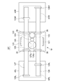
- FIG. 6 is a plan view of the speaker device SP.
- the speaker device SP includes a first speaker unit that emits sound based on an audio signal of the left channel (hereinafter referred to as a left speaker SPL) and a second speaker unit that emits sound based on an audio signal of the right channel (hereinafter, right Speaker SPR).
- the speaker device SP can be used for both music reproduction and musical instrument performance reproduction.
- the speaker device SP is supported by the pole 11, hereinafter, the up and down direction will be referred to based on the state in which the sound emission direction of the speaker device SP faces the floor surface.
- the left-right direction is referred to based on the positional relationship in which the left speaker SPL is on the left and the right speaker SPR is on the right. Accordingly, when the speaker device SP is viewed from the left side of FIG.
- the holding mechanism M mainly includes bases 40L, 120, and 40R, and the holding mechanism M can adjust the relative positional relationship between the speakers SPL and SPR.
- the left speaker SPL is attached to the base 40L
- the right speaker SPR is attached to the base 40R.
- Two guide bars 126, 127 are arranged in parallel over the bases 40L, 120, 40R.
- the connecting part 121 is made of a U-shaped member, and connects the base part 120 and the pole. Both end portions of the connecting portion 121 are fixed to the base portion 120 across the guide bars 126 and 127 upward.
- the connecting portion 121 is connected to the tip end portion 11d of the pole in the vicinity of the center portion thereof.
- the right end portion of the guide bar 126 is fixed to the base portion 40R by a fixing portion 128R.
- the guide bar 126 is slidably held by the sliding support portion 129L with respect to the base portion 40L, and is slidably held by the two sliding support portions 36 with respect to the base portion 120.
- the left end portion of the guide bar 127 is fixed to the base portion 40L by the fixing portion 128L.
- the guide bar 127 is slidably held by the sliding support portion 129R with respect to the base portion 40R, and is slidably held by the two sliding support portions 36 with respect to the base portion 120. Accordingly, the base 40R can move in the left-right direction integrally with the guide bar 126 relative to the base 120, and the base 40L can move in the left-right direction integrally with the guide bar 127 relative to the base 120. Can be moved to.
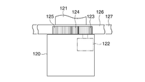
- FIG. 7A is a front view of the base 120.
- a motor 122 is disposed on the base 120.
- a pinion gear 125, a transmission gear 124, and a motor gear 123 are arranged in series between the guide bars 126 and 127 on the upper surface of the base 120.
- the transmission gear 124 meshes with the pinion gear 125 and the motor gear 123.
- the motor gear 123 is connected to the shaft of the motor 122.
- rack gears 126a and 127a are formed on the opposite sides of the guide bars 126 and 127 (the shape is not shown), and the pinion gear 125 is engaged with both rack gears 126a and 127a.
- the guide bars 126 and 127 are displaced in the direction of approaching or separating from each other in the left-right direction.
- the displacement direction of the guide bars 126 and 127 depends on the rotation direction of the motor 122. For example, when the motor 122 rotates in the clockwise direction of FIG. 6, the guide bars 126 and 127 are displaced to the left and right, respectively, and the base portions 40L and 40R both move in a direction approaching the base portion 120. On the other hand, when the motor 122 rotates counterclockwise in FIG.
- the guide bars 126 and 127 are displaced to the right and left, respectively, and the bases 40L and 40R move in a direction away from the base 120.
- the distance between the base portions 40L and 40R is variable by the rotation of the motor 122, and the distance (interval) between the speakers SPL and SPR is variable.
- This function is a distance adjustment function. It is also possible to manually change the distance between the speakers SPL and SPR by manually operating the bases 40L and 40R and the speakers SPL and SPR.
- the support portion 41 is fixed to the lower surface of the base portion 40L.
- the left speaker SPL is supported by the support portion 41 so as to rotate integrally with the shaft portion 42 around the shaft center of the shaft portion 42. Therefore, the left speaker SPL rotates clockwise and counterclockwise when viewed from the front, and the sound emission direction is variable.
- a motor 43 is provided on the lower surface of the base portion 40 ⁇ / b> L adjacent to the support portion 41, and a motor gear 44 is coupled to the shaft of the motor 43.
- a driven gear 46 and a transmission gear 45 are rotatably disposed on the support portion 41.
- the driven gear 46 is fixed to the shaft portion 42, and the rotation center thereof coincides with the shaft center of the shaft portion 42.
- the transmission gear 45 meshes with the motor gear 44 and the driven gear 46.
- the motor gear 44 is rotated by the rotation of the motor 43.
- the rotation is transmitted from the motor gear 44 to the driven gear 46 via the transmission gear 45.
- the shaft portion 42 rotates, and the left speaker SPL rotates in conjunction with the rotation, and the direction changes.
- the direction of the left speaker SPL can be changed according to the rotation direction of the motor 43.
- This function is a direction adjustment function.
- the right speaker SPR and the base 40R are bilaterally symmetric with the left speaker SPL and the base 40L, but the configuration is the same, and thus illustration and detailed description thereof are omitted. Therefore, the direction of the right speaker SPR is also variable.
- the holding mechanism M includes base portions 40L, 120, 40R, guide bars 126, 127, gears 123 to 125, 44 to 46, and motors 122 and 43.
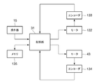
- FIG. 8 is a block diagram of the control mechanism of the speaker system 100.
- the main unit 13 includes a control unit 31 and a nonvolatile memory 135 in addition to the state detection unit 14 and the operation unit 15 (FIG. 5).
- the control unit 31 drives and controls the motors 122 and 43.
- the rotations of the motors 122 and 43 are detected by the encoders 133 and 134, respectively, and the detection results are supplied to the control unit 31.
- the operation unit 15 can be operated by the user.
- the user can perform an operation of changing the interval between the speakers SPL and SPR and an operation of changing each direction of the speakers SPL and SPR with the operation unit 15.
- the control unit 31 sends a drive signal to the motors 122 and 43.
- the control unit 31 refers to the rotation amounts detected by the encoders 133 and 134 and controls the motors 122 and 43 to rotate to the rotation position according to the user's instruction.
- the motors 122 and 43 may be configured as stepping motors, and in that case, the control unit 31 may determine and control the rotational positions of the motors 122 and 43 based on the pulse amount.
- control unit 31 may store information indicating the current rotational positions of the motors 122 and 43 in the memory 135 in accordance with a user instruction, and store the information as a preset position. Then, even if the positions and angles of the speakers SPL and SPR change after the preset position is stored, the control unit 31 may call the information as necessary to reproduce the preset position. This increases convenience.
- the speaker device SP is preferably used in a position above the head of the listener (user) (about 15 cm from the height of the ear). Since the sound generation position of the speaker device SP is close to the listener's ear, even if the sound volume is small, the sound can be delivered to the listener only with a sufficient sound volume. In general, if the position of the ear is out of the sound generation axis of the speaker, it becomes difficult to hear high-frequency sounds with sharp directivity. However, since the speaker device SP is close to the ear, the distance attenuation is small, and even in a configuration with no directivity, it is possible to provide a volume almost equal to that of a flat speaker having directivity including a high sound range.
- the sounding axis of the speaker is usually near the chest of the user's body because the sound is usually played at the feet or on the desk, and the user is on the sounding axis. I rarely hear sound. This makes it difficult to hear high-frequency sounds with sharp directivity.
- the speaker device SP is used, the high-frequency component on the sound generation axis of the speaker can be heard by itself efficiently, so that a tone having characteristics of the high-frequency component such as string cutting and reverberation can be obtained. Sounds clearer and more natural. This is also true for other instruments.
- the user can use the distance adjustment function and the direction adjustment function of the holding mechanism M to adjust the interval and the direction of the speakers SPL and SPR as desired according to the position of both ears and the direction of the head.
- the speakers SPL and SPR are positioned approximately 15 cm above the height of the ear. This is realized by fastening the second straight portion 11a2 with respect to the first straight portion 11a1 with the fastener 18 at a desired position.
- This function is a holding height adjustment function. In this state, the interval between the speakers SPL and SPR is made to coincide with the interval between the two ears, and the interval between the speakers SPL and SPR is made to coincide with the interval between the both ears.
- the sound emission direction of the speakers SPL and SPR may be directed toward their own ears without matching the intervals between the speakers SPL and SPR with the intervals between their ears.
- the entire speaker device SP may be configured to be rotatable by 180 ° about the straight portion 11a of the pole 11 so that the arrangement of the speakers SPL and SPR can be reversed left and right.
- a posture in which the listener faces the straight portion 11a of the pole 11 or a posture in which the listener faces the back of the pole 11 can be used.
- a musical score is played by placing a musical score on a music stand mounted on the mounting unit 16.
- the player sits with the pole 11 in the back to perform or appreciate music. Therefore, convenience is high if the arrangement of the speakers SPL and SPR can be reversed left and right.
- the control unit 31 may invert L / R of the stereo audio signal in accordance with an instruction from the user.
- the holding mechanism M can adjust the relative positional relationship between the left speaker SPL and the right speaker SPR, it can efficiently deliver the sound to the user's ear and to the surroundings. It is possible to deliver a rich volume to the user while reducing sound leakage.
- the distance between the speakers SPL and SPR can be adjusted to match the distance between the user's ears.
- the relative directions of the speakers SPL and SPR can be adjusted to direct the speakers SPL and SPR to the user's ears. As a result, it is possible to deliver sounds having the same characteristics to the left and right ears without being affected by individual differences.
- the holding mechanism M is supported by the pole 11 so that the speakers SPL and SPR of the speaker device SP are always directed downward from the horizontal direction, it is suitable for a usage mode in which sound is emitted above the user. Furthermore, since the holding height of the speaker device SP can be adjusted by operating the fastener 18, the vertical distance from the user's ear can be adjusted.
- the holding mechanism M may be fixed with respect to either the speaker SPL or SPR.
- the base 120 may be fixed to either the base 40L or the base 40R.
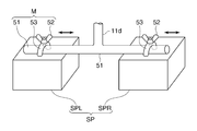
- FIG. 9A is a partial perspective view of the speaker system according to the third embodiment of the present invention. Since the configuration of the stand 10 is the same as that of the second embodiment, the description thereof is omitted.
- the holding shaft 51 is held at the tip 11 d of the curved portion 11 b of the stand 10.
- the holding shaft 51 is long in the left-right direction.
- Annular portion 53 is fixed to each of the speakers SPL and SPR constituting the speaker device SP, and a holding shaft 51 is inserted into a hole of the annular portion 53.
- the engaging position of the holding shaft 51 with respect to the hole of the annular portion 53 is variable in the left-right direction.
- the holding mechanism M mainly includes a holding shaft 51, an annular portion 53, and a fastening portion 52.
- the holding mechanism M can adjust the relative positional relationship (distance, orientation) between the left speaker SPL and the right speaker SPR, so that the sound is efficiently delivered to the user's ear.
- the same effects as those of the second embodiment can be obtained.
- the speaker system 100 includes a distance adjustment function, a direction adjustment function, and a holding height adjustment function.
- the holding mechanism M has at least a distance adjustment function or a direction adjustment function. You should prepare.
- achieves each function is an illustration, and various modifications are employable. A modification will be described with reference to FIGS. 9B, 10A, and 10B.
- FIG. 9B is a diagram showing a modification of the holding mechanism M that realizes the orientation adjustment function.
- the stay 54 is fixed to the upper surface of the speaker SP (at least one of the left and right speakers SP).
- the stay 54 is formed with pressure contact pieces 55 and 56 standing upright.
- a connecting portion 121 is interposed between the pressure contact pieces 55 and 56.
- the connecting part 121 is supported by the tip 11d as in the second embodiment.
- the stay 54 can be rotated around the shaft center X with respect to the connecting portion 121. If the fastening tool 57 is loosened and the stay 54 is rotated with respect to the connecting portion 121, the direction of the speaker SP fixed to the stay 54 can be changed.
- the direction of the axis center X is, for example, the front-rear direction, but is not limited thereto.
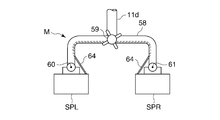
- FIG. 10A is a diagram showing a modification of the holding mechanism M that realizes the orientation adjustment function.
- the holding shaft 58 is held at the tip 11 d of the curved portion 11 b of the stand 10.
- Speakers SPL and SPR are rotatably attached to the two ends of the holding shaft 58.
- the speakers SPL and SPR rotate about the rotation centers 60 and 61, respectively.
- a wire 64 is disposed along the holding shaft 58, and two ends of the wire 64 are attached to the speakers SPL and SPR.
- the intermediate portion of the wire 64 can be taken up by the take-up portion 59. When the wire 64 is taken up by operating the take-up portion 59, the substantial length of the wire 64 can be changed.
- the speakers SPL and SPR are rotated in a direction facing each other.
- the speakers SPL and SPR are always urged by an urging member such as a spring so as to face the floor surface in a free state.
- the user can adjust the degree of facing of the speakers SPL and SPR by operating the winding unit 59.
- the orientation adjustment function in the holding mechanism M described so far is a configuration that realizes rotation in one direction of the speakers SPL and SPR
- a configuration that rotates in any direction may be employed.
- the connecting portion 121 and the stay 63 may be connected via a rotary joint 62.
- the stay 63 is fixed to the upper surface of the speaker SPL, but can also be applied to the speaker SPR. This configuration may be applied to the second embodiment.
- FIGS. 11A and 11B are side views of a speaker unit-integrated self-supporting stand according to a fourth embodiment of the present invention.
- the main unit 13 is disposed at a position close to the leg portion 12 in the pole 11, but may be disposed at the same position as in the first embodiment.
- Other configurations of the stand 10 are the same as those in the first embodiment.
- a speaker unit SP (speaker system 100) integrally provided with the stand 10 is referred to as a speaker unit integrated self-supporting stand.
- This self-supporting stand can be not only self-supporting but also carried by the user and installed at a preferred position.
- the attachment accessory
- the straight portion 11a may be configured so that the accessory can be directly attached (directly attached). Accordingly, the straight portion 11a has a function of attaching the accessory via the attachment portion 16 or directly.
- the leg part 12 is a leg seat part, and the straight part 11a corresponds to a support part extending upward from the leg part 12. And the extended part extended in the direction which cross
- the speaker device SP has a purpose of emitting sound toward the listener 71 located below and giving the listener 71 a feeling like a so-called sound shower. Therefore, the speaker device SP is supported by the bending portion 11b at a position away from the leg portion 12, and a space for the listener 71 is secured below the speaker device SP.
- a range mainly inside the leg portion 12 is a main sound emission range 72 by the speaker device SP. As described above, the height of the speaker device SP can be adjusted.
- the speaker device SP is positioned below the speaker device SP.
- the main sound emission range 72 is appropriately formed. Note that the listener 71 may set an adjustable range so that the height of the speaker device SP can be adjusted in accordance with the height even when the listener 71 is used in a low posture without using a chair or the like.
- the mounting function portion 16 provided in the straight portion 11a, or a portion where the accessory in the straight portion 11a can be attached is referred to as a “mounting function portion”.
- the mounting function unit is located within a range from a position H1 to a position H2 in the vertical direction.
- the position H2 is a position below the speaker device SP whose height is adjusted to the lower limit position.
- the position H2 only needs to be lower than the speaker device SP and does not have to coincide with the upper part 11ah.
- the mounting function unit may be one or a plurality of continuous regions, or may be a plurality of distant locations.
- the mounting function part is provided in at least one of the first straight part 11a1 or the second straight part 11a2, or at least one predetermined position corresponds to the mounting function part.
- the mounting unit 16 is an attachment
- the attachment is a mounting function unit having a function of mounting an accessory.
- the mounting portion 16 may be fixed to the straight portion 11a at the time of product shipment.
- An example in which the mounting portion 16 becomes the attachment 74 will be described later with reference to FIG.
- the straight part 11a itself becomes a mounting function part and fulfills the function of mounting the accessory. This example will also be described later with reference to FIG.
- FIG. 12 is a diagram illustrating an example of an attachment or an accessory attached to the straight portion 11a.
- the attachment 74 (74A to 74F) is illustrated as the mounting portion 16 that is mounted on or fixed in advance to the straight portion 11a.
- the accessory 75 (75A, 75B, 75C) is illustrated as an accessory.
- the attachment 74A is a music score holder, and can hold a music score (not shown) as equipment.
- the attachment 74B is a terminal device holder, and can hold an accessory 75A that is a portable terminal device such as a tablet or a smartphone as equipment.
- the attachment 74C is a microphone stand tray, and can hold a microphone (not shown) as a fixture.
- the attachment 74D is a guitar holder and can hold an accessory 75B which is a guitar as equipment.
- the attachment 74E is a cup holder and can hold an accessory 75C which is a cup as a fixture.
- the attachment 74F is a universal clamp holder and can hold a camera (not shown) as a fixture.
- the main unit 13 is provided with an input terminal 73 in addition to the state detection unit 14 and the operation unit 15.
- the input terminal 73 is included in the signal input unit 33 (FIG. 4).
- An accessory 75 that outputs a signal for sound generation by the speaker device SP can be connected to the input terminal 73, and a signal for sound generation by the speaker device SP is input from the input terminal 73.
- an accessory 75 for generating a speaker, a musical instrument, a portable audio, a smartphone, and the like are conceivable.
- the accessory 75 and the attachment 74 are not limited to those illustrated.
- the speaker device SP is supported by the extending portion (curved portion 11b) extending from the upper portion 11ah of the column portion (straight portion 11a) extending upward from the leg portion 12 to the side.
- the sound is emitted toward the listener 71 located below. Since the user can install the self-supporting speaker system 100 at any position, the degree of freedom of the installation position of the speaker unit can be increased.
- pillar part (straight part 11a) has the function to mount
- the accessory can be placed in the vicinity, which is convenient for managing and handling the accessory.
- the stand 10 is also convenient for selfies.
- the performer can realize an application mode in which the accessory 74B or 74F holds the accessory 75 having a photographing function and records the performance scene together with the performance sound while listening to his / her performance with the speaker device SP.
- FIG. 13A is a cross-sectional view of the straight portion 11a.
- the first straight portion 11a1 and the second straight portion 11a2 are both circular in outer shape, and the first straight portion 11a1 has a larger outer diameter.
- the cross-sectional shape of the 1st straight part 11a1 and the 2nd straight part 11a2 may be similar, it does not need to be similar.
- the straight part 11a may be comprised by three sticks from which an external shape differs, Therefore, it may have three or more area
- the cross-sectional shape of the mounting function unit is not limited to a circular shape or an annular shape, and may have an outer shape such as a rectangle or an ellipse.
- FIG. 13B is a diagram showing a modification in which a non-slip material is provided on the straight portion 11a.
- An anti-slip material 76 is disposed on the outer periphery of at least one of the first straight portion 11a1 and the second straight portion 11a2. Only the region where the anti-slip material 76 is disposed may be used as the mounting function unit.
- the material of the non-slip material 76 is soft resin, cloth, or the like, but the material is not limited.
- FIG. 14 is a schematic diagram of a modified example of the stand 10 having a different shape.
- the speaker device SP is disposed in an extending portion extending in the direction intersecting the vertical direction from the upper portion 11ah of the straight portion 11a. It only has to be done. Therefore, the extending portion may not be a curved shape like the bending portion 11b, and may be a substantially horizontal extending portion 11e as shown in FIG. The extending portion does not need to be curved or horizontal.
- pillar part which has a mounting function part may be one, and may be three or more.
- wearing function part may be fixed integrally with speaker apparatus SP including an extension part.
Landscapes
- Physics & Mathematics (AREA)
- Engineering & Computer Science (AREA)
- Acoustics & Sound (AREA)
- Signal Processing (AREA)
- Obtaining Desirable Characteristics In Audible-Bandwidth Transducers (AREA)
- Details Of Audible-Bandwidth Transducers (AREA)
Abstract
スピーカユニットの設置位置の自由度を高めると共に、スピーカユニット及びアクセサリを1カ所にまとめることができるスピーカユニット一体型の自立式スタンドを提供する。スピーカ装置SPは、脚部12から上方に延びた真直部11aの上部11ahから、上下方向と交差する方向に延設された湾曲部11bに支持され、下方に居る聴取者71に向けて放音する。メインユニット13に含まれる入力端子73には、スピーカ装置SPで発音するための信号を出力するアクセサリ75を接続可能である。ユーザは自立式のスピーカシステム100を自由な位置に設置できる。真直部11aは、スピーカ装置SPより下で、スピーカを利用する際に用いられる備品であるアクセサリを装着する機能を有し、例えば装着部16がその機能を果たす。
Description
本発明は、スピーカユニット一体型の自立式スタンド、及びスピーカシステムに関する。
従来、聴取者の上方にスピーカを設置して、自然な楽器音を提供できるようにした音響システムが知られている(下記特許文献1)。このシステムでは、鉛直方向に延びる支持部材を天井と床面とに固定し、支持部材に取り付けたフレームに平面スピーカを支持している。
しかしながら、上記システムでは、支持部材は固定されているため、スピーカを支持した支持部材の位置を自由に移動させるのは容易でない。そのため、スピーカの設置位置の自由度が高くない。ところで、上記システムの利用の際に、各種のアクセサリが使用される。アクセサリはスピーカを利用する際に用いられる備品であり、例えば、楽器自体や楽器ホルダのほか、譜面台、小物置き等も含まれる。ユーザは、システムの使用時だけでなく非使用時にもアクセサリを近辺に置きたい場合がある。ところが、上記システムは、アクセサリの管理に関して考慮していないため、アクセサリの取り扱いに関し改善の余地がある。
また従来、スピーカ装置は、一般に、左右のチャンネルの音をそれぞれ放音するL側、R側スピーカユニットを有する。ヘッドホンやイヤホンとは異なり、設置型のスピーカ装置は床面や壁等に設置され、L側、R側スピーカユニットの配置は固定的である。ここで、聴取者がスピーカ装置の放音を装置の近くで聞く利用態様を考える。スピーカ装置の近くで音を聞くと、遠くで聞くよりもステレオ感が明瞭となる。それだけでなく、放音位置が耳に近いので距離減衰が少なく、指向性のない構成であっても周囲に大きな音が漏れることなく大きな聴取音量が得られる。
ところが、耳とスピーカユニットとの距離が左右で大きく相違すると違和感が大きい。理想的には、耳とスピーカユニットとの距離が左右で同じで、なおかつ極力距離が短いのがよい。また、スピーカユニットの発音方向は通常、左右で同じである。しかし、スピーカの発音軸(発音方向)から耳の位置が外れていると、指向性の鋭い高音域の音は聞き取りにくくなる。従って、スピーカユニットの近くで音を聞く場合は、遠くで聞く場合と比べ、左右それぞれの耳に対する左右のスピーカユニットの向きのずれの影響が大きくなる。しかも、左右の耳の間隔は体格や年齢などによって約20~26cmと個人差があり、耳とスピーカユニットとの距離によっても、スピーカの発音軸と耳とのずれ量も変化する。自然な音を聞くためには左右の耳に対する左右のスピーカユニットの距離や角度を適切に設定できればよいが、従来のスピーカ装置はそれらが固定的であり、聴取者が自由な姿勢をとるのが困難で、個人差にも対応できないという問題があった。また、ヘッドホンを利用すれば、耳とスピーカとの距離や向きは問題とならないが、装着が煩わしかったりコードが邪魔であったりといった問題がある。
ところで、可動に構成したスピーカ装置が知られている(特許文献2)。しかしながら、この装置は、室内に放射される音の拡がり具合を室内形状に合わせてコントロールすることで音像定位を分散化することを狙ったものであり、1人の聴取者に対する音響を改善するものではない。
本発明の第1の目的は、スピーカユニットの設置位置の自由度を高めると共に、スピーカユニット及びアクセサリを1カ所にまとめることができるスピーカユニット一体型の自立式スタンドを提供することである。
また、本発明の第2の目的は、ユーザの耳へ効率的に音を届けることができるスピーカシステムを提供することである。
上記第1の目的を達成するために本発明によれば、脚座部(12)と、前記脚座部から上方に延びた支柱部(11a)と、前記支柱部の上部から、上下方向と交差する方向に延設された延設部(11b)と、前記脚座部から上方に離れた位置で前記延設部に支持され、下方に居る聴取者(71)に向けて放音するスピーカユニット(SP)と、前記スピーカユニットで発音するための信号が入力される入力部(33、73)と、を有し、前記支柱部は、前記スピーカユニットより下でアクセサリ(75)を装着する機能を有するスピーカユニット一体型の自立式スタンドが提供される。
上記第2の目的を達成するために本発明によれば、左チャンネルの音声信号に基づき放音する第1のスピーカユニットと、
右チャンネルの音声信号に基づき放音する第2のスピーカユニットと、前記第1のスピーカユニット及び前記第2のスピーカユニットを保持し、前記第1のスピーカユニットと前記第2のスピーカユニットとの相対的な位置関係を調整可能である保持機構と、を有するスピーカシステムが提供される。
右チャンネルの音声信号に基づき放音する第2のスピーカユニットと、前記第1のスピーカユニット及び前記第2のスピーカユニットを保持し、前記第1のスピーカユニットと前記第2のスピーカユニットとの相対的な位置関係を調整可能である保持機構と、を有するスピーカシステムが提供される。
なお、上記括弧内の符号は例示である。
本発明によれば、スピーカユニットの設置位置の自由度を高めると共に、スピーカユニット及びアクセサリを1カ所にまとめることができる。
本発明によれば、ユーザの耳へ効率的に音を届けることができる。
以下、図面を参照して本発明の実施の形態を説明する。
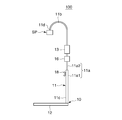
図1A、図1Bはそれぞれ、本発明の一実施の形態に係るスピーカシステムの斜視図、側面図である。このスピーカシステム100は、支持体としてのスタンド10にスピーカ装置SPが支持されて成る。スタンド10は、平面視で略半円状の脚部12と、ポール11とを有する。脚部12は床面に当接する。ポール11は、真直部11a(11a1、11a2)と湾曲部11bとを有し、真直部11aの下端部11cが脚部12に固定されている。湾曲部11bは真直部11aの上端に繋がり、側面視で略半円状に湾曲する。湾曲部11bの先端11dにスピーカ装置SPが取り付けられる。
ポール11の真直部11aは、第1真直部11a1と第2真直部11a2の2本の棒状部材が連結されて成る。例えば、第1真直部11a1に対して第2真直部11a2を挿入し、所望の挿入深さで両者を締結具18で締結することによって、第1真直部11a1に対する第2真直部11a2の固定位置を変えることができる。これにより、真直部11a全体の長さが調整可能になっている。従って、スピーカ装置SPの高さ方向の配置位置を調整できる。ポール11の例えば第2真直部11a2には、メインユニット13、装着部16が配設される。スピーカ装置SP及び装着部16は、メインユニット13に電気的に接続されている。メインユニット13には、状態検知部14及び操作部15が設けられる。
スピーカ装置SPは、左チャンネルの音声信号に基づき放音する第1のスピーカユニット(以下、左スピーカSPLと記す)と、右チャンネルの音声信号に基づき放音する第2のスピーカユニット(以下、右スピーカSPR)とを有する。なお、スピーカ装置SPは、左スピーカSPL、右スピーカSPR以外のスピーカユニットを備える3チャンネル以上の構成としてもよい。スピーカ装置SPは、音楽再生、楽器演奏再生のいずれにも用いることができる。
このスピーカシステム100の使用態様として次のようなものが想定される。例えば、脚部12の半円形状の内側に椅子を置き、椅子に座って音楽を聴いたり、自身で楽器を演奏して演奏音を聞いたりする。また、椅子を置かずに脚部12の半円形状の内側に立って音を聞く態様もある。椅子に座る場合と立つ場合とで、上述のように真直部11aの全長を適宜調整することで、スピーカ装置SPを所望の高さへ調整できる。スピーカシステム100は設置型であり、部屋の隅や壁際に近接させて設置するのに適している。
装着部16は、楽器、備品、補助具、機器等の装着物(アクセサリ)を引っ掛けたり保持したりする機能を有する。装着物のなかの備品や補助具には、楽譜載置台、タブレット、楽器掛けホルダ等が含まれる。装着部16に関しては、第4の実施の形態で詳細に説明する。メインユニット13には、音声信号を出力する機器、例えば、電子楽器、音楽プレーヤ等を接続できる。メインユニット13はアンプ機能や信号処理機能を備え、接続された機器から供給される音声信号をスピーカ装置SPで発音させる。接続される電子楽器には、消音機能を有するアコースティック楽器も含まれる。電子音の発生の際にアコースティック音があまり大きく発生しない楽器に特に適している。
スピーカ装置SPは、聴取者の頭部の上方の位置(耳の高さから約15cm)に位置させて用いるのが好適である。スピーカ装置SPの発音位置が聴取者の耳に近いことで、小さな発音音量であっても聴取者だけには十分な音量で音を届けることができる。一般に、スピーカの発音軸から耳の位置が外れていると、指向性の鋭い高音域の音は聞き取りにくくなる。しかし、スピーカ装置SPが耳に近いので距離減衰が少なく、指向性のない構成であっても、高音域を含め、指向性のある平面スピーカとほぼ同等の音量を提供できる。従って、外部への音漏れを著しく少なくすることができる。また、聴取者の上方から放音されるので、身体への装着物が不要で邪魔にならず、しかも物体や身体の一部で遮られることもないので、自然な音を聞くことができる。従って、ヘッドホンで聴くよりも自然な聞こえ方が実現される。また、上方からの放音であるので、真横からの放音に比べ、頭部が左右に少し移動しても音質や音量の変化が少なくて済む。
なお、聴取者がスピーカ装置SPの直下に居るとして、聴取者がポール11の真直部11aと正対する姿勢を第1姿勢とし、聴取者がポール11に背を向ける姿勢を第2姿勢とする。スピーカシステム100を第1姿勢で利用するときは、ポール11に対して向かって左側に左スピーカSPL、右側に右スピーカSPRが位置するのが適切である。例えば、聴取者が装着部16に装着した楽譜載置台に譜面を置いて楽器演奏する場合等である。一方、スピーカシステム100を第2姿勢で利用するときは、ポール11に対して向かって左側に右スピーカSPR、右側に左スピーカSPLが位置するのが適切である。例えば、ポール11が聴取者の視界や動作を遮ることがないようにポール11を背にして着座して演奏や音楽鑑賞をする場合等である。また、スピーカシステム100を利用する際、第1姿勢、第2姿勢のいずれでもない姿勢となる場合もある。例えばトロンボーンやトランペット等の演奏時には、壁やポール11に楽器が干渉しないように、少し斜めの姿勢(鉛直方向から見て第1姿勢と第2姿勢との間の姿勢となる、第1姿勢または第2姿勢から少し回転した位置)で演奏する場合、あるいはメインユニットの操作を聴取者の真横で操作できるようにする場合等が想定される。この場合、各スピーカSPL、SPRの位置を姿勢に合わせて調整できると都合がよい。そこで本実施の形態では、各スピーカSPL、SPRの配置を、左右反転を含めてその間の所望の位置で安定するように調整する機能(安定機構)を設けている。
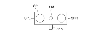
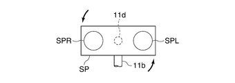
図2Aは、スピーカ装置SPの側面図である。図2B~図2Dは、スピーカ装置SPを下方から見た図である。スピーカ装置SPは、スタンド10の湾曲部11bの先端11dに、軸支部20を介して双方向に回転自在に保持される。すなわちスピーカ装置SPは、先端11dの軸中心を中心として回転可能である。軸支部20が、スピーカ装置SPに対して異なる聴取位置が取れるように、左スピーカSPLの位置と右スピーカSPRの位置とが互いに異なる2つ以上の位置で安定するようにする「安定機構」の主要部となる。
スピーカ装置SPは、図2B、図2Dで、それぞれ第1姿勢、第2姿勢に対応する回転位置となっている。スピーカ装置SPは、図2Cでは、第1姿勢と第2姿勢との間の姿勢に対応する回転位置となっていて、例えば図2Bに示す位置から紙面左回り45°回転した状態を示し、聴取者がポール11に対して正対する状態から右に45°斜めを向く姿勢を取るときあるいはポール11を背にして左に45°斜めを向く姿勢を取るときに適した状態を示している。なお、聴取者がポール11に対して正対する状態から左に45°斜めを向く姿勢を取るとき、あるいはポール11を背にして右に45°斜めを向く姿勢を取るときに適した状態とするときには、図2Bの状態からスピーカSPRが紙面下側45°(スピーカSPLが紙面上側45°)の位置を取って安定するようにすればよい。
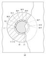
図3は、スピーカ装置SPにおける軸支部20周りを下方から見た図であり、見やすくするために一部を断面で示している。軸支部20はスピーカ装置SPに固定されている。軸支部20には穴21が形成されている。先端11dは穴21に挿通され、且つ穴21から抜けないように軸支部20に係合している。穴21には、円周方向において複数の山部が形成され、山部と山部との間の谷部が凹部22(22-1~22-9)となっている。一方、先端11dの外周部に1つの突部17が突出して形成されている。
スピーカ装置SPは、ユーザ(聴取者)が手動で回転させることができる。先端11dの直径は穴21の内径よりもやや小さい。突部17がいずれかの凹部22に係合している状態では、先端11dの回転方向の位置が安定する。スピーカ装置SPを回転させると、先端11dが穴21に対して相対的に回転し、穴21の山部を乗り越えると次の凹部22に嵌って回転位置が安定する。従って、安定保持される回転位置は複数ある。具体的には、突部17が凹部22-1と係合している図3に示す状態は、図2Bに示す状態であり第1姿勢に対応する。図3に示す状態からスピーカ装置SPを図3の反時計方向(図2B~図2Dの反時計方向)へ180°回転させると、突部17は凹部22-9と係合し、図2図2Dに示す第2姿勢に対応する回転位置となる。回転の途中で突部17を凹部22-3に係合させると、図2Cに示す状態となる。スピーカ装置SPの回転可能な角度範囲は、突部17が凹部22-1または凹部22-9と係合する位置で決まり、ほぼ180°に規制される。
なお、図3で例示した機構によれば複数段階で安定保持される箇所があるが、この構成に限るものではない。例えば、突部17を廃止し、先端11dの外周面と穴21とを摺接させ、両者の摩擦によりスピーカ装置SPを任意の回転位置で安定させる構成としてもよい。あるいは、任意の回転位置で別途の固定具で先端11dと軸支部20とを締め付ける等によって位置を安定させる構成でもよい。なお、スピーカ装置SPを回転駆動するモータ等の駆動部を設け、操作部15での操作に応じた回転位置へスピーカ装置SPを回転駆動するように構成してもよい。
このように、スピーカ装置SPを先端11dに対して物理的に回転させることで、各スピーカSPL、SPRの放音位置を変化させることが可能で、使用する姿勢が第1姿勢か第2姿勢かによって放音位置を反転させることも簡単である。
また、本実施の形態ではさらに、スピーカシステム100は、放音位置を電気的に切り替える機能を備える。これを図4で説明する。
図4は、スピーカシステム100の制御機構のブロック図である。メインユニット13には、状態検知部14及び操作部15(図1)のほか、制御部31、信号処理部32、信号入力部33が備えられる。信号入力部33には、電子楽器や音楽プレーヤ等の音声信号出力機器から出力されるステレオの音声信号が入力され、入力された音声信号は信号処理部32に供給される。信号処理部32はアンプや信号切り替えの機能も有しており、ステレオ音声信号をスピーカSPL、SPRへ出力する。その際、信号処理部32は、ステレオ音声信号のL/Rを反転させることができる。ここで、左スピーカSPL、右スピーカSPRにそれぞれ、左、右チャンネルの音声信号を供給するモードを第1モードとし、左スピーカSPL、右スピーカSPRにそれぞれ、右、左チャンネルの音声信号を供給するモードを第2モードとする。信号処理部32はモードを切り替えることができる。
装着検知部34は装着部16(図1)に備えられ、装着部16に上述の装着物が装着されたことを検知して、検知信号を制御部31及び信号処理部32へ供給する。装着検知部34の構成は問わず、例えば、接触式、導電式等が考えられる。状態検知部14は、センサやカメラ等を有し、スピーカシステム100の使用状態を検知する。例えば状態検知部14は、赤外線、超音波、可視光等を用いた人感センサとして構成され、スピーカ装置SPの15cm程度下の領域の物体(人)の存在を検知し、検知信号を制御部31及び信号処理部32へ供給する。状態検知部14が物体を検知しているときは、スピーカ装置SPの直下に聴取者が居て、スピーカシステム100が使用中であると判断される。
なお、状態検知部14が備えるカメラで撮影した画像を制御部31が解析し、スピーカ装置SPの直下に聴取者が居るかどうか、さらには聴取者がどちらの方向を向いているか(第1姿勢か第2姿勢か)を判断するようにしてもよい。このように、状態検知部14はスピーカシステム100の使用状態を検知できればよく、その構成は問わない。また、状態検知部14は複数のセンサを組み合わせて構成してもよい。検知される使用状態は、最低限、スピーカ装置SPが使用中か否かであればよく、より好ましくは、聴取者の姿勢(向き)や位置を検知できるとよい。なお、状態検知部14からの検知信号に限定されず、装着検知部34からの検知信号に基づき、スピーカシステム100の使用状態(どのような楽器または音楽装置が接続されているのか)を制御部31が判断するようにしてもよい。
操作部15はユーザによって操作可能である。簡単な構成例としては、操作部15がアンプにおける信号のL/Rの切り替え手段として機能し、操作部15の操作に応じて信号処理部32はモードを切り替える。一方、検知されたスピーカシステム100の使用状態の検知結果に基づいて信号処理部32はモードを切り替えることも可能である。この場合、使用状態によってどのモードに切り替えるのかを予めユーザが設定できるようにしてもよい。そして、例えば、専ら第2姿勢でのみ楽器を演奏するユーザは、演奏時のモードとして第2モードを設定しておく。ユーザが離れた位置でスピーカシステム100を利用する場合、例えば再生される音楽を遠くで聞く場合は、スピーカ装置SPの下に居ないため、モードは第1モードとなる。一方、ユーザが楽器を演奏するためにスピーカ装置SPの下に移動すると、存在が検知されて、自動的にモードが第2モードに切り替わる。このように、状況に応じて自動的に左右の放音位置が反転するので便利である。なお、ユーザの向きまで検知できるようにした場合は、向きの応じてどのモードを採用するのかを予め設定しておけばよい。
また、装着部16に、電子楽譜、歌詞、演奏支援画面、動画等を表示させる機器が接続されたことが装着検知部34により検知されると、ユーザは壁側を向くことが想定されるので、自動的に第1モードが採用されるようにしてもよい。このほか、操作部15におけるエフェクタの操作がなされたときは、自動的に第1モードが採用されるようにしてもよい。
本実施の形態によれば、スピーカ装置SPが、左スピーカSPLの位置と右スピーカSPRの位置とが反転可能なようにスタンド10に支持されるので、左右の放音位置を反転可能にする等、互いに異なる2つ以上の位置で安定させることで、使い勝手を高めることができる。特に、スピーカ装置SPを手動で回転させることが可能であるので、簡単な構成で使い勝手がよい。また、任意の回転角度で使用することも可能であるので、楽器の種類に応じた位置に左右の放音位置を設定でき、利便性が高い。さらに、スピーカシステムの使用状態に基づいてモードを切り替えることで、状況に応じて自動的に左右の放音位置を反転可能にすることができ、使い勝手が高まる。
なお、設置型のスピーカ装置において、左スピーカSPLの位置と右スピーカSPRの位置とは、最低限、聴取者が適切に聴取する状態が互い異なる2つの位置で安定した状態が保つことができればよく、回転できる構成は必須でない。例えば、支持体に対して着脱して位置を変えるものとしてもよい。また、左右の放音位置の反転は、手動による構成と信号切り替えによる構成の双方を備えることは必須でなく、いずれか一方のみを備える構成であってもよい。
(第2の実施の形態)
図5A、図5Bはそれぞれ、本発明の第2の実施の形態に係るスピーカシステムの斜視図、側面図である。本実施の形態では、湾曲部11bの先端11dに、連結部121を介してスピーカ装置SPが取り付けられる。これ以外のスタンド10の構成は第1の実施の形態と同様である。
図5A、図5Bはそれぞれ、本発明の第2の実施の形態に係るスピーカシステムの斜視図、側面図である。本実施の形態では、湾曲部11bの先端11dに、連結部121を介してスピーカ装置SPが取り付けられる。これ以外のスタンド10の構成は第1の実施の形態と同様である。
図6は、スピーカ装置SPの平面図である。スピーカ装置SPは、左チャンネルの音声信号に基づき放音する第1のスピーカユニット(以下、左スピーカSPLと記す)と、右チャンネルの音声信号に基づき放音する第2のスピーカユニット(以下、右スピーカSPR)とを有する。スピーカ装置SPは、音楽再生、楽器演奏再生のいずれにも用いることができる。スピーカ装置SPはポール11に支持されているが、以下、スピーカ装置SPの放音方向が床面を向いている状態を基準として上下方向を呼称する。左右方向については、左スピーカSPLが左で右スピーカSPRが右となる位置関係を基準として呼称する。従って、図5Bの左側からスピーカ装置SPを見るとき、正面視とされる。
左スピーカSPL及び右スピーカSPRは保持機構Mによって保持され、保持機構Mはポール11に支持される。詳細は図6、図7で説明するが、保持機構Mには主として基部40L、120、40Rが含まれ、保持機構Mによって両スピーカSPL、SPRの相対的な位置関係を調整可能である。図6に示すように、基部40Lには左スピーカSPLが取り付けられ、基部40Rには右スピーカSPRが取り付けられる。基部40L、120、40Rにかけて2本のガイドバー126、127が平行に配置されている。連結部121は、U字状の部材で成り、基部120とポールとを連結する。連結部121の両端部は、ガイドバー126、127を上方で跨いで基部120に固定されている。また、連結部121は、その中央部付近でポールの先端部11dと接続される。ガイドバー126の右端部は固定部128Rにより基部40Rに固定される。ガイドバー126は、基部40Lに対して摺動支持部129Lで摺動自在に保持されると共に、基部120に対して2つの摺動支持部36で摺動自在に保持される。一方、ガイドバー127の左端部は固定部128Lにより基部40Lに固定される。ガイドバー127は、基部40Rに対して摺動支持部129Rで摺動自在に保持されると共に、基部120に対して2つの摺動支持部36で摺動自在に保持される。これにより、基部40Rは、基部120に対して相対的に、ガイドバー126と一体に左右方向に移動可能で、基部40Lは、基部120に対して相対的に、ガイドバー127と一体に左右方向に移動可能である。
図7Aは、基部120の正面図である。図6、図7Aに示すように、基部120にはモータ122が配設される。また、基部120の上面においてガイドバー126、127間に、ピニオンギア125、伝達ギア124、モータギア123が直列に配列される。伝達ギア124はピニオンギア125とモータギア123とに噛み合っている。モータギア123はモータ122の軸に連結されている。一方、ガイドバー126、127の互いに対向する側には、ラックギア126a、127aが形成されており(形状は図示せず)、ピニオンギア125は両ラックギア126a、127aに噛み合っている。モータ122が回転すると、モータギア123から伝達ギア124を介してピニオンギア125へ回転が伝達される。その結果、ガイドバー126、127が左右方向における互いに近接するあるいは離間する方向へ変位する。ガイドバー126、127の変位方向はモータ122の回転方向に応じる。例えば、モータ122が図6の時計方向に回動するとガイドバー126、127がそれぞれ左方、右方へ変位し、基部40L、40Rはいずれも基部120に対して近づく方向へ移動する。一方、モータ122が図6の反時計方向に回動するとガイドバー126、127がそれぞれ右方、左方へ変位し、基部40L、40Rはいずれも基部120から離れる方向へ移動する。このように、モータ122の回転によって基部40L、40R間の距離が可変となり、ひいては両スピーカSPL、SPR間の距離(間隔)が可変となる。この機能が距離調整機能である。なお、基部40L、40RやスピーカSPL、SPRを手で操作してスピーカSPL、SPR間の距離を手動で変化させることも可能である。
図7B、図7Cはそれぞれ、基部40L及び左スピーカSPLの側面図、正面図である。基部40Lの下面に支持部41が固定される。左スピーカSPLは、軸部42の軸中心を中心に軸部42と一体に回動するよう支持部41に支持される。従って、左スピーカSPLは、正面から見て時計及び反時計方向に回動し、放音方向が可変となっている。基部40Lの下面に、支持部41に隣接してモータ43が設けられ、モータ43の軸にはモータギア44が連結される。支持部41には被駆動ギア46、伝達ギア45が回転自在に配置される。被駆動ギア46は軸部42に固定され、その回転中心は軸部42の軸中心と一致している。伝達ギア45は、モータギア44と被駆動ギア46とに噛み合っている。
モータギア44はモータ43の回転によって回転する。モータ43が回転すると、モータギア44から伝達ギア45を介して被駆動ギア46へ回転が伝達される。すると軸部42が回動し、それに連動して左スピーカSPLが回動し、向きが変わる。モータ43の回転方向によって、左スピーカSPLの向きを変えることができる。この機能が向き調整機能である。右スピーカSPR及び基部40Rに関しては、左スピーカSPL及び基部40Lと左右対称であるが構成は同様であるので、その図示及び詳細説明を省略する。従って、右スピーカSPRについても向きが可変である。
なお、各スピーカSPL、SPRは個別に向き(発音軸)が可変であり、手動によって個別に向きを調整することもできる。なお、各スピーカSPL、SPRの可動範囲は、それぞれ、常に水平方向よりも下の方向を向く範囲である。保持機構Mには、基部40L、120、40R、ガイドバー126、127、ギア123~125、44~46、モータ122、43が含まれる。
図8は、スピーカシステム100の制御機構のブロック図である。メインユニット13には、状態検知部14及び操作部15(図5)のほか、制御部31、不揮発性のメモリ135が備えられる。制御部31はモータ122、43を駆動制御する。モータ122、43の回転は、それぞれエンコーダ133、134によって検出され、その検出結果が制御部31に供給される。
操作部15はユーザによって操作可能である。ユーザは、操作部15で、スピーカSPL、SPRの間隔を変更する操作、及び、スピーカSPL、SPRの各向きを変更する操作を行える。操作部15の操作に応じて、制御部31はモータ122、43へ駆動信号を送る。その際、制御部31は、エンコーダ133、134で検出される回転量を参照して、ユーザの指示に応じた回転位置へモータ122、43を回転させるよう制御する。なお、モータ122、43はステッピングモータとして構成してもよく、その場合、制御部31はパルス量によってモータ122、43の回転位置を判断及び制御してもよい。
なお、制御部31は、現在のモータ122、43の回転位置を示す情報をユーザの指示に応じてメモリ135に記憶しておき、プリセット位置として保存するようにしてもよい。そして制御部31は、プリセット位置の保存後にスピーカSPL、SPRの位置や角度が変化したとしても、必要に応じて情報を呼び出し、プリセット位置を再現するようにしてもよい。これにより利便性が高まる。
スピーカ装置SPは、聴取者(ユーザ)の頭部の上方の位置(耳の高さから約15cm)に位置させて用いるのが好適である。スピーカ装置SPの発音位置が聴取者の耳に近いことで、小さな発音音量であっても聴取者だけには十分な音量で音を届けることができる。一般に、スピーカの発音軸から耳の位置が外れていると、指向性の鋭い高音域の音は聞き取りにくくなる。しかし、スピーカ装置SPが耳に近いので距離減衰が少なく、指向性のない構成であっても、高音域を含め、指向性のある平面スピーカとほぼ同等の音量を提供できる。従って、外部への音漏れを著しく少なくすることができる。また、聴取者の上方から非接触で放音されるので、身体へ直接装着する物が不要でイヤホンやヘッドホンのように邪魔になることがないとともに長時間の使用でも不快感を生じることがない。しかも物体や身体の一部で遮られることもないので、自然な音を聞くことができる。従って、ヘッドホンで聴くよりも自然な聞こえ方が実現される。また、上方からの放音であるので、真横からの放音に比べ、頭部が左右に少し移動しても音質や音量の変化が少なくて済む。
このように、上方から至近距離で音を聞くことで、イヤホンやヘッドホンの使用時よりも自然な聞こえ方が実現される。例えば、ヴァイオリンの演奏では上方向に音が放射され、天井からの反射音が聞こえる。トランペットやトロンボーンの演奏では、放射音が譜面台や壁・天井等で反射した音が聞こえる。従って、これらの楽器の演奏音をスピーカ装置SPで鳴らすと、耳元の真横から鳴るイヤホン・ヘッドホンよりも聞こえ方が自然に近くなる。また、ギターの演奏音をスピーカ装置SPで発音させると、これまでのオーディオ・アンプでは聞けなかった「本当に聞きたい音」が聞けるという点で、より自然な聞こえ方となる。すなわち、従来、スピーカからギター音を聞く場合、通常は足元で鳴らしたり机の上で鳴らしたりするため、スピーカの発音軸はユーザの身体の胸あたりになることが多く、ユーザは発音軸上の音を聞くことがほとんどない。そのため、指向性が鋭くなる高域の音は聞きづらくなる。しかし、スピーカ装置SPを用いれば、スピーカの発音軸上の高域成分を効率的に自分だけで聞くことができるため、弦のカッティングや響き等、高域成分が特徴を成している音色がよりクリアに自然に聞こえる。このことは、他の楽器でもいえることである。
ユーザは、保持機構Mの距離調整機能や向き調整機能を用いて、自身の両耳の位置や頭部の向きに合わせてスピーカSPL、SPRの間隔と向きとを所望に調整できる。例えば、耳の高さから約15cm上方にスピーカSPL、SPRを位置させる。これは、第1真直部11a1に対する第2真直部11a2の固定位置を所望位置にして締結具18で締結することによって実現される。この機能が保持高さ調整機能である。この状態で、スピーカSPL、SPRの間隔を自身の両耳の間隔に一致させると共に、スピーカSPL、SPRの間隔を自身の両耳の間隔と一致させる。あるいは、スピーカSPL、SPRの間隔を自身の両耳の間隔と一致させなくても、スピーカSPL、SPRの放音方向を自身の耳へ向けてもよい。
ところで、各スピーカSPL、SPRの配置を左右反転できるように、スピーカ装置SPの全体をポール11の真直部11aを中心に180°回転可能に構成してもよい。聴取者がスピーカ装置SPの直下に居るとして、聴取者がポール11の真直部11aと正対する姿勢と、聴取者がポール11に背を向ける姿勢とのいずれでも利用され得る。例えば、装着部16に装着した楽譜載置台に譜面を置いて楽器演奏する場合等がある。一方、ポール11を背にして着座して演奏や音楽鑑賞をする場合もある。従って、各スピーカSPL、SPRの配置を左右反転できると利便性が高い。なお、ステレオ音声信号をスピーカSPL、SPRへ出力する際、ユーザからの指示に応じて制御部31がステレオ音声信号のL/Rを反転させるようにしてもよい。
本実施の形態によれば、保持機構Mは、左スピーカSPLと右スピーカSPRとの相対的な位置関係を調整可能であるので、ユーザの耳へ効率的に音を届けることができ、周囲への音漏れを小さくしつつユーザには豊かな音量を届けることができる。特に、スピーカSPL、SPR間の距離を調整してユーザの耳の間隔に合わせることができる。また、スピーカSPL、SPRの相対的な向きを調整して各スピーカSPL、SPRをユーザの各耳へ向けることができる。これらにより、個人差の影響を受けることなく、左右の耳に同じ特性の音を届けることができる。
また、スピーカ装置SPの各スピーカSPL、SPRが常に水平方向よりも下の方向を向くように保持機構Mがポール11に支持されるので、ユーザの上方で放音する使用態様に適する。さらに、締結具18を操作して、スピーカ装置SPの保持高さを調整可能であるので、ユーザの耳に対する上下方向の距離を調整可能にすることができる。
なお、スピーカSPL、SPRの距離(間隔)や向きは、互いに相対的に可変であればよい。従って、保持機構MはスピーカSPL、SPRのいずれかに対して固定的であってもよい。例えば、基部120は基部40Lまたは基部40Rのいずれかに固定されていてもよい。
(第3の実施の形態)
図9Aは、本発明の第3の実施の形態に係るスピーカシステムの部分斜視図である。スタンド10の構成は第2の実施の形態と同じであるのでその説明を省略する。スタンド10の湾曲部11bの先端11dに、保持軸51が保持される。保持軸51は左右方向に長い。スピーカ装置SPを構成するスピーカSPL、SPRにはそれぞれ、環状部53が固定され、環状部53の穴に保持軸51が挿通されている。環状部53の穴に対する保持軸51の係合位置は左右方向に可変である。保持軸51が挿通された状態で各々の環状部53の外側から締結部52を締め付けることで、その位置で保持軸51に対してスピーカSPL、SPRが固定される。これにより、スピーカSPL、SPR間の距離を任意の距離に固定することができる。またその際、保持軸51に対する環状部53の回転方向の角度も任意に調整できる。従って、締結部52を締め付けることで、スピーカSPL、SPR間の相対的な向きも任意に調整できる。本実施の形態では、保持機構Mには、主として保持軸51、環状部53及び締結部52が含まれる。
図9Aは、本発明の第3の実施の形態に係るスピーカシステムの部分斜視図である。スタンド10の構成は第2の実施の形態と同じであるのでその説明を省略する。スタンド10の湾曲部11bの先端11dに、保持軸51が保持される。保持軸51は左右方向に長い。スピーカ装置SPを構成するスピーカSPL、SPRにはそれぞれ、環状部53が固定され、環状部53の穴に保持軸51が挿通されている。環状部53の穴に対する保持軸51の係合位置は左右方向に可変である。保持軸51が挿通された状態で各々の環状部53の外側から締結部52を締め付けることで、その位置で保持軸51に対してスピーカSPL、SPRが固定される。これにより、スピーカSPL、SPR間の距離を任意の距離に固定することができる。またその際、保持軸51に対する環状部53の回転方向の角度も任意に調整できる。従って、締結部52を締め付けることで、スピーカSPL、SPR間の相対的な向きも任意に調整できる。本実施の形態では、保持機構Mには、主として保持軸51、環状部53及び締結部52が含まれる。
本実施の形態によれば、保持機構Mは、左スピーカSPLと右スピーカSPRとの相対的な位置関係(距離、向き)を調整可能であるので、ユーザの耳へ効率的に音を届けることに関し、第2の実施の形態と同様の効果を奏することができる。
なお、第2、第3の実施の形態では、スピーカシステム100として、距離調整機能、向き調整機能及び保持高さ調整機能を備えたが、保持機構Mは、少なくとも距離調整機能または向き調整機能を備えればよい。また、各機能を実現する構成は例示であり、各種の変形例を採用可能である。図9B、図10A、図10Bで変形例を説明する。
図9Bは、向き調整機能を実現する保持機構Mの変形例を示す図である。ステイ54はスピーカSP(左右のスピーカSPの少なくとも一方)の上面に固定される。ステイ54には、圧接片55、56が立設して形成される。圧接片55、56間に連結部121が介在する。連結部121は、第2の実施の形態と同様に先端11dに支持される。連結部121に対して、軸中心Xを中心にステイ54が回動可能である。締め付け具57を緩めてステイ54を連結部121に対して回動させれば、当該ステイ54に固定したスピーカSPの向きを変えることができる。一方、締め付け具57を締め付けると、圧接片55、56が互いに近接して連結部121を強く挟むことにより、その回動位置でステイ54は回転しなくなる。軸中心Xの方向は、例えば前後方向であるが、それに限定されない。
図10Aは、向き調整機能を実現する保持機構Mの変形例を示す図である。スタンド10の湾曲部11bの先端11dに、保持軸58が保持される。保持軸58の2つの各先端にスピーカSPL、SPRが回動自在に取り付けられる。スピーカSPL、SPRはそれぞれ、回動中心60、61を中心に回動する。保持軸58に沿って、ワイヤ64が配設され、ワイヤ64の2つの各先端がスピーカSPL、SPRに取り付けられている。ワイヤ64の中間部分は巻き取り部59で巻き取り可能であり、巻き取り部59を操作してワイヤ64を巻き取ると、ワイヤ64の実質的な全長を変えることができる。ワイヤ64の実質的な全長を短くすると、スピーカSPL、SPRが互いに向き合う方向に回動する。なお、スピーカSPL、SPRは、自由状態では床面を向くように、バネ等の付勢部材によって常に付勢されている。ユーザは、巻き取り部59を操作することでスピーカSPL、SPRの向き合いの度合いを調整することができる。
なお、これまで説明した保持機構Mにおける向き調整機能は、スピーカSPL、SPRの一方向への回動を実現する構成であったが、任意の方向へ回動する構成を採用してもよい。例えば、図10Bに示すように、ロータリージョイント62を介して連結部121とステイ63とを連結してもよい。ステイ63はスピーカSPLの上面に固定されるが、スピーカSPRについても適用可能である。この構成は、第2の実施の形態に適用してもよい。
(第4の実施の形態)
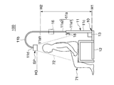
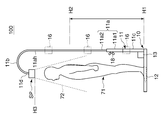
図11A、図11Bは、本発明の第4の実施の形態に係るスピーカユニット一体型の自立式スタンドの側面図である。メインユニット13は、ポール11における脚部12に近い位置に配置されるが、第1の実施の形態と同様の位置に配置されてもよい。スタンド10におけるその他の構成は第1の実施の形態と同様である。
図11A、図11Bは、本発明の第4の実施の形態に係るスピーカユニット一体型の自立式スタンドの側面図である。メインユニット13は、ポール11における脚部12に近い位置に配置されるが、第1の実施の形態と同様の位置に配置されてもよい。スタンド10におけるその他の構成は第1の実施の形態と同様である。
本実施の形態では、スタンド10にスピーカユニットであるスピーカ装置SPが一体に設けられたもの(スピーカシステム100)を、スピーカユニット一体型の自立式スタンドと称する。この自立式スタンドは、自立できるだけでなく、ユーザが運んで好みの位置に設置できる。第1~第3の実施の形態では、装着物(アクセサリ)はポール11の真直部11aに装着部16を介して保持されるとした。しかし、真直部11aはアクセサリを直接に(直付けで)装着可能に構成されてもよい。従って、真直部11aは、装着部16を介して、あるいは直接に、アクセサリを装着する機能を有する。
脚部12は脚座部であり、真直部11aは脚部12から上方に延びた支柱部に該当する。そして、真直部11aの上部11ahから、上下方向と交差する方向に延設された延設部が、湾曲部11bである。スピーカ装置SPは、下方に居る聴取者71に向けて放音し、いわゆる音のシャワーのような感覚を聴取者71に与える目的を有する。そのために、スピーカ装置SPは、脚部12から上方に離れた位置で湾曲部11bに支持され、スピーカ装置SPの下方に、聴取者71が居られる空間が確保されている。主として脚部12の内側の範囲が、スピーカ装置SPによる主放音範囲72となっている。なお、上述のように、スピーカ装置SPの高さ調整が可能であり、聴取者71が椅子等に着座しても(図11A)、起立しても(図11B)、スピーカ装置SPの下方に主放音範囲72が適切に形成される。なお、聴取者71は、椅子等を使わず低い姿勢で使用する場合でも、それに適合してスピーカ装置SPの高さを調整できるように、調整可能範囲を設定してもよい。
ここで、真直部11aに設けられた装着部16、または真直部11aにおけるにおけるアクセサリを取り付け可能な箇所を、「装着機能部」と称する。装着機能部は、上下方向における位置H1から位置H2までの範囲内に位置する。位置H2は、高さが下限位置に調整されたスピーカ装置SPよりも下の位置である。位置H2はスピーカ装置SPよりも下方であればよく、上部11ahと一致しなくてもよい。装着機能部は連続する1つまたは複数の領域でもよく、離れた複数箇所でもよい。装着機能部は、第1真直部11a1または第2真直部11a2の少なくとも一方に設けられるか、または少なくとも一方の所定位置が装着機能部に該当する。装着部16が設けられる場合は、装着部16はアタッチメントとなり、アタッチメントはアクセサリを装着する機能を有する装着機能部となる。この場合、製品出荷時点で装着部16は真直部11aに固定されていてもよい。装着部16がアタッチメント74となる例は図12で後述する。一方、真直部11aにアクセサリを直接取り付ける場合は、真直部11a自身が装着機能部となり、アクセサリを装着する機能を果たす。この例も図12で後述する。
図12は、真直部11aに装着されるアタッチメントまたはアクセサリの例を示す図である。図12では、真直部11aに対して装着または予め固定される装着部16としてアタッチメント74(74A~74F)が例示される。アクセサリとしてアクセサリ75(75A、75B、75C)が例示される。例えば、アタッチメント74Aは譜面ホルダであり、備品である譜面(不図示)を保持できる。アタッチメント74Bは端末装置ホルダであり、備品としてタブレットやスマートフォン等の携帯型端末装置であるアクセサリ75Aを保持できる。アタッチメント74Cはマイクスタンド用トレイであり、備品であるマイク(不図示)を保持できる。アタッチメント74Dはギターホルダであり、備品としてギターであるアクセサリ75Bを保持できる。アタッチメント74Eはカップホルダであり、備品としてコップであるアクセサリ75Cを保持できる。アタッチメント74Fはユニバーサルクランプホルダであり、備品であるカメラ(不図示)等を保持できる。
ところで、図12に示すように、メインユニット13には、状態検知部14及び操作部15のほか、入力端子73が設けられている。入力端子73は信号入力部33(図4)に含まれる。入力端子73には、スピーカ装置SPで発音するための信号を出力するアクセサリ75を接続可能であり、入力端子73から、スピーカ装置SPで発音するための信号が入力される。このようなスピーカ発音用のアクセサリ75として、楽器、携帯オーディオ、スマートフォン等が考えられる。アクセサリ75やアタッチメント74は例示したものに限定されない。
本実施の形態によれば、スピーカ装置SPは、脚部12から上方に延びた支柱部(真直部11a)の上部11ahから側方へ延設された延設部(湾曲部11b)に支持され、下方に居る聴取者71に向けて放音する。ユーザは自立式のスピーカシステム100を自由な位置に設置できるので、スピーカユニットの設置位置の自由度を高めることができる。また、支柱部(真直部11a)は、スピーカ装置SPより下でアクセサリを装着する機能を有するので、スピーカユニット及びアクセサリを1カ所にまとめることができる。ユーザにとっては、スピーカ装置SPの使用時だけでなく非使用時にもアクセサリを近辺に置くことができ、アクセサリの管理や取り扱いに関し便利になる。また、スタンド10は自分撮りにも便利である。例えば演奏者は、アタッチメント74Bまたは74Fに、撮影機能を有したアクセサリ75を保持させ、自身の演奏をスピーカ装置SPで聞きながら演奏風景を演奏音と共に記録するといった利用態様を実現できる。
図13Aは、真直部11aの断面図である。一例として、第1真直部11a1及び第2真直部11a2はいずれも外形が円形の環状であり、第1真直部11a1の方が外径は大きい。第1真直部11a1及び第2真直部11a2の断面形状は相似でもよいが、相似でなくてもよい。また、真直部11aは、外形の異なる3本の棒で構成されてもよく、従って、断面形状の異なる3つ以上の領域を装着機能部として有してもよい。すなわち、真直部11aは、装着機能部として断面形状が合同でない少なくとも2つの領域を有してもよい。これにより、装着可能なアクセサリやアタッチメントのサイズや種類が多くなる。なお、装着機能部の断面形状は円形や円環状に限らず、矩形や楕円等の外形形状を有していてもよい。
図13Bは、真直部11aに滑り止め材を設けた変形例を示す図である。第1真直部11a1及び第2真直部11a2の少なくとも一方の外周に、滑り止め材76が配設される。滑り止め材76が配設された領域だけを装着機能部として利用してもよい。滑り止め材76の材質は軟質樹脂や布等であるが、材質は問わない。滑り止め材76を設けることで、アクセサリやアタッチメントの装着状態を安定させることができる。
図14は、形状を変えたスタンド10の変形例の模式図である。スピーカ装置SPの下方に聴取者71が居ることができるスペースを確保する観点からは、真直部11aの上部11ahから、上下方向と交差する方向に延設された延設部にスピーカ装置SPが配置されればよい。従って、延設部は湾曲部11bのような湾曲形状でなくてもよく、図14に示すように、ほぼ水平な延設部11eであってもよい。延設部は湾曲や水平な形状である必要はない。
なお、装着機能部を有する支柱部は1本であってもよいし、3本以上でもよい。また、装着機能部を有する支柱部は延設部を含めスピーカ装置SPと一体に固定されていてもよい。
以上、本発明をその好適な実施形態に基づいて詳述してきたが、本発明はこれら特定の実施形態に限られるものではなく、この発明の要旨を逸脱しない範囲の様々な形態も本発明に含まれる。
本出願は、2016年8月4日に出願された日本出願第2016-153593号及び日本出願第2016-153594号に基づく優先権を主張するものであり、当該日本出願に記載された全内容を本出願に援用する。
10 スタンド
11a 真直部(支柱部)
11ah 上部
11b 湾曲部(延設部)
12 脚部(脚座部)
73 入力端子(入力部)
74 アタッチメント
75 アクセサリ
SP スピーカ装置(スピーカユニット)
11a 真直部(支柱部)
11ah 上部
11b 湾曲部(延設部)
12 脚部(脚座部)
73 入力端子(入力部)
74 アタッチメント
75 アクセサリ
SP スピーカ装置(スピーカユニット)
Claims (6)
- 脚座部と、
前記脚座部から上方に延びた支柱部と、
前記支柱部の上部から、上下方向と交差する方向に延設された延設部と、
前記脚座部から上方に離れた位置で前記延設部に支持され、下方に居る聴取者に向けて放音するスピーカユニットと、
前記スピーカユニットで発音するための信号が入力される入力部と、を有し、
前記支柱部は、前記スピーカユニットより下でアクセサリを装着する機能を有するスピーカユニット一体型の自立式スタンド。 - 前記アクセサリは、前記入力部に接続可能であり、前記信号を出力する請求項1に記載のスピーカユニット一体型の自立式スタンド。
- 前記支柱部自身が前記アクセサリを装着する機能を果たす請求項1または2に記載のスピーカユニット一体型の自立式スタンド。
- 前記支柱部は、断面形状が合同でない少なくとも2つの領域を有し、各領域が前記アクセサリを装着する機能を果たす請求項3に記載のスピーカユニット一体型の自立式スタンド。
- 前記支柱部はアタッチメントを有し、前記アタッチメントを介して前記アクセサリを装着可能である請求項1または2に記載のスピーカユニット一体型の自立式スタンド。
- 左チャンネルの音声信号に基づき放音する第1のスピーカユニットと、
右チャンネルの音声信号に基づき放音する第2のスピーカユニットと、
前記第1のスピーカユニット及び前記第2のスピーカユニットを保持し、前記第1のスピーカユニットと前記第2のスピーカユニットとの相対的な位置関係を調整可能である保持機構と、を有するスピーカシステム。
Applications Claiming Priority (4)
| Application Number | Priority Date | Filing Date | Title |
|---|---|---|---|
| JP2016153593 | 2016-08-04 | ||
| JP2016-153594 | 2016-08-04 | ||
| JP2016-153593 | 2016-08-04 | ||
| JP2016153594 | 2016-08-04 |
Publications (1)
| Publication Number | Publication Date |
|---|---|
| WO2018025959A1 true WO2018025959A1 (ja) | 2018-02-08 |
Family
ID=61072924
Family Applications (1)
| Application Number | Title | Priority Date | Filing Date |
|---|---|---|---|
| PCT/JP2017/028228 Ceased WO2018025959A1 (ja) | 2016-08-04 | 2017-08-03 | スピーカユニット一体型の自立式スタンド、及びスピーカシステム |
Country Status (1)
| Country | Link |
|---|---|
| WO (1) | WO2018025959A1 (ja) |
Citations (3)
| Publication number | Priority date | Publication date | Assignee | Title |
|---|---|---|---|---|
| JP2007221484A (ja) * | 2006-02-16 | 2007-08-30 | Sony Corp | スピーカ装置 |
| JP3182513U (ja) * | 2013-01-17 | 2013-04-04 | 劉力行 | 角度と位置が調整可能な音響密閉箱フレーム |
| JP2016046612A (ja) * | 2014-08-21 | 2016-04-04 | 株式会社暁電工 | 屋外自立型放送拡声装置 |
-
2017
- 2017-08-03 WO PCT/JP2017/028228 patent/WO2018025959A1/ja not_active Ceased
Patent Citations (3)
| Publication number | Priority date | Publication date | Assignee | Title |
|---|---|---|---|---|
| JP2007221484A (ja) * | 2006-02-16 | 2007-08-30 | Sony Corp | スピーカ装置 |
| JP3182513U (ja) * | 2013-01-17 | 2013-04-04 | 劉力行 | 角度と位置が調整可能な音響密閉箱フレーム |
| JP2016046612A (ja) * | 2014-08-21 | 2016-04-04 | 株式会社暁電工 | 屋外自立型放送拡声装置 |
Similar Documents
| Publication | Publication Date | Title |
|---|---|---|
| JP5026622B2 (ja) | デュアル構成のスピーカー | |
| CN103596088B (zh) | 具有枢轴部件的耳机 | |
| US10129631B2 (en) | System and method for open to closed-back headset audio compensation | |
| US20110150262A1 (en) | Headset | |
| JP4407622B2 (ja) | テレビジョン装置 | |
| CN101026893B (zh) | 扬声器设备 | |
| JP4983630B2 (ja) | 放収音装置 | |
| TW201521457A (zh) | 耳機型音響裝置 | |
| JP2009218888A (ja) | 放音システム | |
| WO1995020866A1 (en) | Audio reproducing device and headphones | |
| CN109478404A (zh) | 可调节的声透镜和扬声器组件 | |
| KR100689576B1 (ko) | 음향 출력 장치 | |
| WO2018025959A1 (ja) | スピーカユニット一体型の自立式スタンド、及びスピーカシステム | |
| JP2018023111A (ja) | スピーカシステム | |
| JPWO2013042324A1 (ja) | 音響再生装置 | |
| US4437189A (en) | Sound system for a musical instrument | |
| JP7161653B2 (ja) | ウエアラブル音響装置 | |
| WO2019155650A1 (ja) | スピーカ装置、及び制御方法 | |
| JP5377030B2 (ja) | マイクロホン装置 | |
| JP2019121896A (ja) | 首掛け型スピーカー装置 | |
| JP2019121897A (ja) | 首掛け型スピーカー装置 | |
| JP3122244U (ja) | 音響器具結合型の卓上電気スタンド | |
| JP2017175256A (ja) | ヘッドホン | |
| JPH0698384A (ja) | スピーカー装置 | |
| US11330362B2 (en) | Acoustic device |
Legal Events
| Date | Code | Title | Description |
|---|---|---|---|
| 121 | Ep: the epo has been informed by wipo that ep was designated in this application |
Ref document number: 17837060 Country of ref document: EP Kind code of ref document: A1 |
|
| NENP | Non-entry into the national phase |
Ref country code: DE |
|
| 122 | Ep: pct application non-entry in european phase |
Ref document number: 17837060 Country of ref document: EP Kind code of ref document: A1 |
|
| NENP | Non-entry into the national phase |
Ref country code: JP |