WO2018025859A1 - 吸引カテーテル及び吸引カテーテルの製造方法 - Google Patents
吸引カテーテル及び吸引カテーテルの製造方法 Download PDFInfo
- Publication number
- WO2018025859A1 WO2018025859A1 PCT/JP2017/027896 JP2017027896W WO2018025859A1 WO 2018025859 A1 WO2018025859 A1 WO 2018025859A1 JP 2017027896 W JP2017027896 W JP 2017027896W WO 2018025859 A1 WO2018025859 A1 WO 2018025859A1
- Authority
- WO
- WIPO (PCT)
- Prior art keywords
- tube
- suction port
- suction
- vertical direction
- lumen
- Prior art date
- Legal status (The legal status is an assumption and is not a legal conclusion. Google has not performed a legal analysis and makes no representation as to the accuracy of the status listed.)
- Ceased
Links
Images






Classifications
-
- A—HUMAN NECESSITIES
- A61—MEDICAL OR VETERINARY SCIENCE; HYGIENE
- A61B—DIAGNOSIS; SURGERY; IDENTIFICATION
- A61B17/00—Surgical instruments, devices or methods
- A61B17/22—Implements for squeezing-off ulcers or the like on inner organs of the body; Implements for scraping-out cavities of body organs, e.g. bones; for invasive removal or destruction of calculus using mechanical vibrations; for removing obstructions in blood vessels, not otherwise provided for
-
- A—HUMAN NECESSITIES
- A61—MEDICAL OR VETERINARY SCIENCE; HYGIENE
- A61M—DEVICES FOR INTRODUCING MEDIA INTO, OR ONTO, THE BODY; DEVICES FOR TRANSDUCING BODY MEDIA OR FOR TAKING MEDIA FROM THE BODY; DEVICES FOR PRODUCING OR ENDING SLEEP OR STUPOR
- A61M25/00—Catheters; Hollow probes
-
- A—HUMAN NECESSITIES
- A61—MEDICAL OR VETERINARY SCIENCE; HYGIENE
- A61M—DEVICES FOR INTRODUCING MEDIA INTO, OR ONTO, THE BODY; DEVICES FOR TRANSDUCING BODY MEDIA OR FOR TAKING MEDIA FROM THE BODY; DEVICES FOR PRODUCING OR ENDING SLEEP OR STUPOR
- A61M25/00—Catheters; Hollow probes
- A61M25/01—Introducing, guiding, advancing, emplacing or holding catheters
Definitions
- One aspect of the present invention relates to a suction catheter for sucking and removing substances in the body outside the body and a method for manufacturing the suction catheter.
- Patent Document 1 discloses a thrombus suction catheter that introduces a tube having a suction port on the distal side into a blood vessel to reach a lesion site, and sucks and removes a thrombus from the suction port. Is disclosed.
- Such a catheter is required to suppress lumen blockage due to aspirated thrombus. Therefore, a catheter with a larger lumen inner diameter has been proposed. It is conceivable that a catheter having a large inner diameter of the lumen has high suction performance and can prevent the lumen from being blocked. However, further improvement is required in view of the peripheral reachability of the suction port of the catheter.
- an object of one aspect of the present invention is to provide a suction catheter and a suction catheter manufacturing method capable of suppressing lumen blockage by a suction substance.
- a suction catheter includes a tube having a lumen extending from the proximal side to the distal side, and a suction port formed on the distal side of the lumen, and the suction port has one end.
- Proximal end of the suction port in the tube arrangement in which the other end is disposed on the distal side and the other end is disposed on the proximal side the distal end of the suction port is vertically upward, and the proximal end of the suction port is vertically downward
- a part including the lower end in the vertical direction is located on the same cross section orthogonal to the first direction in which the lumen extends and extends in the vertical direction when the tube is viewed from the side orthogonal to the first direction and the vertical direction.
- the curvature at the proximal end of the suction port is smaller than the curvature at the distal end.
- a substance such as a thrombus or a foreign substance sucked by the suction catheter is sucked into the lumen from the proximal portion in the first direction of the suction port.
- the substance sucked by the suction catheter is passed through the lumen from the lower part of the suction port of the tube. Inhaled.
- a part including the lower end in the vertical direction at the proximal end of the suction port is located on the same cross section orthogonal to the first direction and extends in the vertical direction when the tube is viewed from the side.
- the thrombus When a thrombus approaches a portion extending in the vertical direction, the thrombus is pulled proximally by a suction force, and the thrombus is easily cut.
- the curvature (degree of bending) at the proximal end of the suction port is smaller than the curvature at the distal end, that is, suction
- the radius of curvature at the proximal end of the mouth is greater than the radius of curvature at the distal end.
- the curvature includes the case where the curvature is 0, that is, the case where the curvature is a straight line. As a result, the blockage of the lumen by the suction substance can be suppressed.
- the curvature of the proximal end portion of the suction port may be 1.74 ⁇ 10 3 rad / m or less.
- the occlusion suppression effect can be further increased.
- rad / m is a unit of curvature and indicates degree (angle) / perimeter (length).
- the proximal end of the suction port when the suction port is viewed from below in the vertical direction, the proximal end of the suction port is linear in the width direction orthogonal to both the first direction and the vertical direction. It may extend to.
- the orthogonal here includes substantially orthogonal.
- the curvature at the proximal end of the suction port when the suction port is viewed from below in the vertical direction, the curvature at the proximal end of the suction port can be easily made smaller than the curvature at the distal end.
- a suction catheter includes a tube having a lumen extending from the proximal side to the distal side, and a suction port formed on the distal side of the lumen, and the suction port has one end.
- Proximal end of the suction port in the tube arrangement in which the other end is disposed on the distal side and the other end is disposed on the proximal side the distal end of the suction port is vertically upward, and the proximal end of the suction port is vertically downward
- a part including the lower end in the vertical direction is located on the same cross section orthogonal to the first direction in which the lumen extends and extends in the vertical direction when the tube is viewed from the side orthogonal to the first direction and the vertical direction.
- the proximal end of the suction port extends linearly in the width direction orthogonal to both the first direction and the vertical direction.
- a part including the lower end in the vertical direction at the proximal end of the suction port is located on the same cross section orthogonal to the first direction and the vertical direction when the tube is viewed from the side.
- the proximal end of the suction port extends linearly in the width direction, so that it is easy to cut the thrombus.
- the orthogonal here includes substantially orthogonal.
- a method of manufacturing a suction catheter is a method of manufacturing a suction catheter including a tube having a substance suction port on a distal side, and using a cutting member having a linear cutting portion, the tube Cutting a part of the tube along a cross section perpendicular to the first direction in which the tube extends.
- the tube including the lower end in the vertical direction at the proximal end of the suction port is located on the same cross section orthogonal to the first direction and extends in the vertical direction when the tube is viewed from the side.
- the thrombus can be easily cut, so that the lumen can be blocked.
- a method of manufacturing a suction catheter includes a step of inserting a core material into the tube before cutting the tube with a cutting member, a step of removing the core material from the tube after cutting the tube with the cutting member, May further be included.
- the proximal end of a predetermined length can be easily formed by inserting the core into the tube.
- the blockage of the lumen by the suction substance can be suppressed.
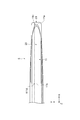
- FIG. 1 is a cross-sectional view of a suction catheter according to an embodiment when cut along a first direction.
- FIG. 2 is a diagram showing a cross-sectional configuration along the line AA in FIG.
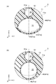
- FIG. 3 is a diagram showing a cross-sectional configuration along the line DD in FIG. 4A is a diagram showing a cross-sectional configuration along the line CC in FIG. 1, and
- FIG. 4B is a diagram showing a cross-sectional configuration along the line BB in FIG.
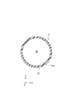
- FIG. 5 is a bottom view of the suction port of the suction lumen in FIG. 1 as viewed from below in the vertical direction.
- FIG. 6A and FIG. 6B are diagrams for explaining an example of the steps of the suction catheter manufacturing method of FIG. FIG.
- FIGS. 7 is a bottom view of a suction port in a suction lumen according to a different embodiment as viewed from below in the vertical direction.
- FIGS. 8A to 8D are examples of cross-sectional views of a suction lumen in a catheter according to a modification.
- FIGS. 9A to 9H are examples of cross-sectional views of a suction lumen in a catheter according to a modification.
- the suction catheter 1 is introduced into the body and used to suck and remove the thrombus generated in the blood vessel from the body by negative pressure applied from the proximal side of the suction catheter 1.
- the same elements may be denoted by the same reference numerals, and redundant descriptions may be omitted.
- the operation side (left side in FIG. 1) of the suction catheter 1 is defined as the proximal side, and the opposite side to the operation side of the suction catheter 1
- the side (right side in FIG. 1) to be introduced into the head is defined as the distal side. 1 to 6,
- the first direction in which the suction catheter 1 extends is the X-axis direction
- the vertical direction is the Z-axis direction
- the width of the suction lumen 10 is the direction perpendicular to the first direction and the vertical direction.
- the direction may be indicated as the Y-axis direction.
- the first direction in which the suction catheter 1 extends is also the longitudinal direction when the suction catheter 1 is viewed from the side.
- the suction catheter 1 has a suction lumen 10 extending from the proximal end to the distal end, and a guide wire lumen 20 extending along the suction lumen 10 on the distal side of the suction lumen 10. is doing.
- the suction lumen 10 serves as a flow path for a thrombus or the like sucked from a suction port 11 provided at the distal end of the suction lumen.
- the guide wire lumen 20 is a lumen through which a guide wire (not shown) for guiding the suction port 11 of the suction lumen 10 to the target site is passed.
- the portion where the suction lumen 10 extends alone is referred to as the first shaft 3
- the portion where the suction lumen 10 and the guide wire lumen 20 extend side by side is referred to as the second shaft 5.
- the first shaft 3 is formed from a first tube 31 that forms the suction lumen 10.
- the first tube 31 is a hollow member extending in one direction, and a cross section perpendicular to the longitudinal direction (hereinafter simply referred to as “cross section”) is an annular member.
- the inner surface 31a of the first tube 31 forms the suction lumen 10, and the suction lumen 10 extends from the proximal side to the distal side.
- the first tube 31 is formed of a resin material. Examples of the resin material include at least one selected from polyamide resin, polyamide elastomer, polyurethane resin, polyether resin, polyester resin, polyimide resin, and polyethylene resin.
- the first tube 31 may be a member including an inner layer and an outer layer.
- the material forming the inner layer include polytetrafluoroethylene (PTFE), tetrafluoroethylene / perfluoroalkyl vinyl ether copolymer (PFA), tetrafluoroethylene / hexafluoropropylene copolymer (FEP), and tetrafluoroethylene.
- -Fluorine resins such as ethylene copolymer (ETFE), polyvinylidene fluoride (PVDF), polychlorotrifluoroethylene (PCTFE), high-density polyethylene and the like are included.
- the material forming the outer layer include elastomers such as polyamide elastomer, polyester elastomer, and polyolefin elastomer.
- a braided tube may be used as the first tube 31.
- the braided tube is a tube including a braided structure made of resin or metal in a tube formed of resin or the like.
- the braided structure is, for example, a structure formed by a knitted linear object provided around the lumen of the tube.
- the braided structure may be a structure in which one wire is wound or a structure arranged along a lumen. Since the material or structure of the braid constituting the braided tube does not limit the effect of one aspect of the present invention, various materials or structures can be used.
- Metal can be used as the material of the braid.
- Stainless steel such as SUS304 and SUS316, spring steel, piano wire, oil temper wire, Co-Cr alloy, Ni-Ti alloy, etc. It is possible to use a metal that has been processed into a braid with one or more metal wires processed into a shape.
- the first shaft 3 may have a double tube structure in which another tube is disposed inside or outside the first tube 31.
- a hub 35 is provided at the proximal end 3 b of the first shaft 3.
- a suction device such as a syringe is connected to the hub 35 via, for example, a Y-shaped connector (not shown).
- the negative pressure suction force by the suction device is applied to the suction lumen 10 of the first tube 31 through the hub 35.
- the hub 35 is made of, for example, a styrene-butadiene copolymer.
- the proximal end 31 b of the first tube 31 is bonded to the hub 35 with an adhesive 37.
- the adhesive 37 is, for example, a urethane adhesive.
- the suction lumen 10 of the first tube 31 communicates with the opening 35 a of the hub 35.
- the second shaft 5 is formed by a second tube (tube) 41 and a third tube 61.
- the second tube 41 has a suction lumen 10 extending in the first direction from the proximal side to the distal side
- the third tube 61 has a guide wire lumen 20 extending in the first direction from the proximal side to the distal side.
- the second tube 41 and the third tube 61 are shown in a state different from the main body resin 71 as shown in FIG.
- the outer shape of the three tubes 61 may not be the shape shown in FIG. That is, the boundary between the second tube 41, the third tube 61, and the main body resin 71 may be indefinite.
- the second tube 41 is a hollow member extending in the first direction and is formed of a resin material.
- the suction lumen 10 is formed by the inner surface 41 a of the second tube 41.
- the example of the resin material which forms the 2nd tube 41 is the same as the example of the material which forms the 1st tube 31 demonstrated in the upper stage.
- the second tube 41 may be a member including an inner layer and an outer layer, and the material thereof may be the same as that of the first tube 31.
- a braided tube may be used as the second tube 41, and an example of the material may be the same as that of the first tube 31.
- the distal end (not shown) of the first tube 31 and the proximal end (not shown) of the second tube 41 are connected to each other, and the suction lumen 10 of the first tube 31 and the suction lumen of the second tube 41 are connected. 10 communicate with each other.
- the same tube may be disposed through the first shaft 3 and the second shaft 5.
- the second tube 41 may extend from the first shaft 3 to the second shaft 5.
- the first tube 31 and the second tube 41 may be integrally formed as a single tube, or a plurality of different tubes may be connected on the way.
- the first tube 31 and the second tube 41 may be formed of the same resin material.
- tubes formed of the same resin material may be connected, or tubes formed of different resin materials may be connected.
- the connecting portion may connect the tubes using an adhesive or a connecting member, or may melt and connect the tubes.
- the distal end surface 41b of the second tube 41 is inclined. Specifically, the distal end surface 41b of the second tube 41 is inclined at a predetermined angle with respect to the direction (first direction) in which the second tube 41 extends. Specifically, as shown in FIG. 1, the distal end surface 41 b of the second tube 41 extends from the distal side to the proximal side so that the upper end is the distal side and the lower end is the proximal side. Inclined continuously. The end surface 41 b is open and communicates with the suction lumen 10. A configuration in which a part of the end surface 41b is closed may be employed. The inclination may be linear as viewed from the side, or may be curved.
- the end surface 41b may have any shape as long as the upper end is on the distal side and the lower end is on the proximal side.
- the end surface 41b may change in a staircase shape by providing a step or the like. There may be.
- the suction port 11 is provided at the distal end of the second tube 41.
- the suction port 11 is formed including part or all of the end face 41b.
- the suction port 11 is provided along the longitudinal direction of the second tube 41, and one end is disposed on the distal side and the other end is disposed on the proximal side.
- length L0 (refer FIG. 1) in the 1st direction from the proximal end 11b to the distal end 11a in the suction port 11 can be 2.0 mm or more and 10 mm or less, for example.
- the suction port 11 provided in the end surface is inclined with respect to the surface orthogonal to the first direction of the suction lumen 10.
- the distal end 11 a of the suction port 11 is on the upper side in the vertical direction and the proximal end 11 b of the suction port 11 is on the lower side in the vertical direction when viewed from the side.
- a part of the proximal end portion 11d including the lower end in the vertical direction at the proximal end 11b of the suction port 11 is located on the same cross section orthogonal to the first direction and the second tube 41 is moved in the first direction and the vertical direction. It extends in the vertical direction when viewed from the orthogonal side (Y-axis direction).
- the curved shape of the proximal end portion 11 d including the proximal end 11 b on the proximal side when viewed from the vertically downward direction is a distal end including the distal end 11 a. It may be different from the curved shape of the side end portion 11c. Specifically, the curve radius in the curved shape of the proximal end portion 11d is larger than the curve radius in the curved shape of the distal end portion 11c. That is, the bending state (curvature) in the curved shape of the proximal end portion 11d is smaller than the bending state (curvature) in the curved shape of the distal end portion 11c.
- the effective portion for cutting the thrombus at the suction port 11 is increased, and the thrombus is easily cut.
- the suction lumen 10 can be prevented from being blocked by a suction substance such as a thrombus.
- the curvature of the proximal end portion 11d of the suction port 11 may be 1.74 ⁇ 10 3 rad / m or less. Thereby, the obstruction
- the curved shape of the proximal end 111d including the proximal end 11b on the proximal side when viewed from the vertically downward direction is shown in the width direction (Y-axis direction). ) May be formed along a straight line. This is also an example when the curvature on the proximal side is made smaller (curvature 0).
- curvature 0 the curvature on the proximal side is made smaller.
- the third tube 61 is a hollow member extending in one direction, and is formed of a resin material.
- the guide wire lumen 20 is formed by the inner surface 61 a of the third tube 61.
- An opening 21 and an opening 22 are provided at the distal end and the proximal end of the third tube 61, respectively.
- the opening 21 and the opening 22 are formed along a plane orthogonal to the first direction of the suction lumen 10.
- the third tube 61 is made of a resin material.
- the example of the resin material which forms the 3rd tube 61 is the same as the example of the material which forms the 1st tube 31 demonstrated in the upper stage.
- the third tube 61 may be a member including an inner layer and an outer layer, and the material thereof may be the same as that of the first tube 31.
- a braided tube may be used as the third tube 61, and the example of the material may be the same as that of the first tube 31.
- the first tube 31, the shaft and the second tube 41, and the third tube 61 may have a multilayer structure including a plurality of resin materials or other materials.
- the resin materials may be the same or different from each other.
- a metal ring or plate or the like may be arranged in a portion facing the lumen of the tube or other portion.
- a resin or metal wire can be wound around the tube.
- the third tube 61 may be provided with a marker (not shown) formed of a material that is opaque to X-rays (radiation).
- the marker is, for example, an annular member formed of an alloy containing gold, platinum, tungsten, platinum (Pt), and indium (Ir).
- the marker is attached to the third tube 61 so as to surround the third tube 61 in the circumferential direction. Accordingly, the operator can grasp the position of the distal end of the second shaft 5 based on the X-ray transmission image.
- the second tube 41 and the third tube 61 are integrally formed.
- the third tube 61 is integrated with a main body resin 71 formed of a resin material in a state where the third tube 61 is arranged above the second tube 41 in the vertical direction.
- the main body resin 71 is formed of a thermoplastic resin, for example, a polyamide elastomer (PAE) or a polyamide elastomer.
- PAE polyamide elastomer
- the main body resin 71 is formed, for example, by heating a shrink tube placed on the second tube 41 and the third tube 61. Thereby, the outer surface (outer shape) 71a of the second shaft 5 is formed.
- the integration may be a state in which the boundaries of the second tube 41, the third tube 61, and the main body resin 71 are unclear, and even if the respective boundaries are clear as shown in FIG. Good.
- the second tube 41, the third tube 61, and three members of different tube materials may be integrated, or two lumens may be formed in one member and the three members may be integrated. Only the second tube 41 and the third tube 61 may be integrated. In this case, the main body resin 71 is formed by the dissolved second tube 41 and third tube 61.
- the cross section of the suction lumen 10 formed by the inner surface 41a of the second tube 41 may change from the proximal side to the distal side.
- the cross section of the suction lumen 10 at the first position P1 where the proximal end 11b of the suction port 11 is present is defined as a first cross section.
- the first cross section is formed by an arc-shaped first inner surface 42 and a second inner surface (bottom) 43 having a smaller curvature than the first inner surface 42.
- the maximum width portion 13 having the maximum length w in the width direction (Y-axis direction) in the first cross section may be located below the vertical center position M in the first cross section. Further, the maximum length h in the vertical direction of the first cross section may be shorter than the maximum length w in the width direction.
- the first cross section may have a horizontally long shape.
- the second tube 41 having such a cross section for example, by inserting a stainless steel core material having a cross section substantially the same shape as the first cross section into a tube having a substantially circular cross section manufactured by extrusion molding, It can be manufactured by heating the tube.
- the shape of the first cross section of the suction lumen 10 may continue from the first position P1 to the proximal side by a predetermined distance L1. Thereby, a substance can be inhaled more smoothly.
- the cross-section switching unit 15 that switches from the first cross section to a second cross section (see FIG. 4B) having a shape different from the first cross section at a position closer to the first position P1 in the first direction is It may be formed starting from a second position P2 that is a predetermined distance L1 away from the first position P1 in the direction.
- the distance L1 between the first position P1 and the second position P2 can be set to 2 mm to 20 mm, for example. Moreover, the lower limit value of the distance L1 can be 2 mm or more, and the upper limit value of the distance can be 10 mm or less.
- the cross-section switching unit 15 is arranged starting from a second position P2 that is 20 mm from the first position P1 in the first direction. This makes it possible to more reliably suppress clogging due to a thrombus in the vicinity of the suction port 11 and more reliably impart vibration to the second tube 41. The reason why the vibration is imparted more reliably is that the sucked suction substance easily collides with the inner surface of the tube, and the vibration due to the collision of the suction substance with the shaft becomes stronger.
- the cross-section switching unit 15 changes the cross-sectional shape of the suction lumen 10 from the first cross-section (see FIG. 3) to the second cross-section (see FIG. 4B) having a different shape and cross-sectional area from the first cross-section. It may be changed.
- the cross-section switching unit 15 may be a taper formed on at least a part of the inner surface 41 a of the second tube 41 that forms the suction lumen 10.
- the cross-section switching unit 15 is formed from the second position P2 to the third position P3 of the second tube 41.
- Such a shape change makes it easier for the thrombus to be cut.
- Such a shape change also has an effect of promoting the efficiency of sucking the thrombus and suppressing the thrombus in the second tube 41, that is, the suction lumen 10 from being blocked.
- the cross-section switching unit 15 may change the cross-sectional shape of the suction lumen 10 gently by a taper provided on the inner surface (inner wall) of the suction lumen 10, or may change it by a step provided in place of the taper. Good. A plurality of cross-section switching portions 15 having such a taper or a step may be provided.
- the cross-sectional shape of the suction lumen 10 formed by the inner surface 41a of the second tube 41 is substantially circular.
- the suction lumen 10 has the shape of the second cross section extending to the proximal end 3 b of the first shaft 3, that is, the hub 35.
- the dashed-two dotted line shown by Fig.4 (a) and FIG.4 (b) has shown the 2nd inner surface 43 which is a part of the inner surface 41a in a 1st cross section.
- the shape or cross-sectional area (size) of the suction lumen 10 may change one or more times between the third position P3 and the hub 35.
- the cross-sectional shape or cross-sectional area of the suction lumen 10 changes, the sucked suction substance easily collides with the inner surface of the tube, and the thrombus suction state can be grasped.
- the change in cross-sectional shape or cross-sectional area may be a change in which the distal side is small and the proximal side is large.
- the suction catheter 1 of this embodiment can be more smoothly introduced into the blood vessel.
- the suction catheter 1 In manufacturing the suction catheter 1, first, the first tube 31, the second tube 41, and the third tube 61 are prepared. Each tube is formed of the above material by extrusion. Subsequently, a marker is attached to the third tube 61. The marker is caulked and fixed to the third tube 61.
- the second tube 41 is cut along a cross section orthogonal to the longitudinal direction (first direction) of the second tube 41 by a cutting member having a linear cutting portion. A part of the second tube 41 is cut. Thereby, a cutting line C1 is formed in the second tube 41.
- FIG. 6B when the second tube 41 is viewed from the side perpendicular to the longitudinal direction of the second tube 41, the second tube 41 is separated from the cutting line C1 by the cutting member. Cutting is performed so that an inclined cutting line C2 is formed.
- the second tube 41 is cut along the cutting line C1 and the cutting line C2, so that a part including the lower end in the vertical direction at the proximal end of the suction port 11 is on the same cross section orthogonal to the first direction.
- a proximal end portion 11d that is positioned and extends in the vertical direction when the second tube 41 is viewed from the side perpendicular to the first direction and the vertical direction is formed.
- the cutting line C1 forms a linear proximal end portion 11d extending in the vertical direction at the proximal end 11b of the suction port 11 when the suction catheter 1 is viewed from the side.
- a cutting member which has a linear cutting part a razor or scissors etc. are mentioned, for example.
- the cutting member that forms the cutting line C2 may be the same as the cutting member that forms the cutting line C1, or may be different from the cutting member that forms the cutting line C1.
- the distal end of the first tube 31 is connected to the proximal end of the second tube 41.
- the second tube 41 and the third tube 61 to which the first tube 31 is connected are arranged in parallel.
- the third tube 61 is arranged so that the distal end of the third tube 61 protrudes distally with respect to the distal end of the second tube 41.
- the method of connecting the first tube and the second tube can be appropriately selected such as bonding with an adhesive or heating and welding the tube.
- a stainless steel core material is inserted into the second tube 41 and the third tube 61.
- the cross section of the core material is circular.
- As the cross-sectional shape of the core material a shape other than a circle can be selected as necessary.
- the second tube 41 and the third tube 61 are covered with a shrink tube and heated.
- the shrink tube may be formed of a heat resistant resin. For example, an olefin resin is mentioned. Thereby, the 2nd tube 41 and the 3rd tube 61 are welded and integrated. Thereby, the main body resin 71 is formed.
- a stainless steel core material is inserted into the second tube 41.
- the cross section of the core material has substantially the same cross-sectional shape as the first cross section formed by the inner surface 41a of the second tube 41 as shown in FIG.
- Examples of the cross-sectional shape of the core material that can be selected include the shapes shown in FIGS.
- a stainless steel core material is inserted into the third tube 61. You may use the core material used at the above-mentioned heating process as it is.
- the shrink tube is covered and heated, the second tube 41 is also heated, and the shape of the inner surface 41a of the second tube 41 is formed into the shape of the inserted core material. Thereby, the suction lumen 10 having the first cross section shown in FIG. 3 is formed.
- the core material having substantially the same cross-sectional shape as the first cross-section is inserted only on the distal side of the second tube 41.
- the heat generated by inserting and heating the core material is transmitted to the portion of the second tube 41 where the core material is not inserted, whereby the tapered cross-section switching unit 15 is formed.
- the circular section formed first by the core material has substantially the same cross-sectional shape as the first cross section.
- the taper-shaped cross-section switching portion 15 is formed by continuously deforming into the first cross-section portion formed by the core material.
- the hub 35 is connected to the proximal end of the first tube 31 with an adhesive 37.
- the suction catheter 1 is manufactured through the above steps.
- the first cross section is formed by the arc-shaped first inner surface 42 and the second inner surface 43 having a smaller curvature than the first inner surface 42 is given.
- the first cross section may have any shape, but if it is formed so that the maximum width portion 13 in the first cross section is located below the vertical center position M in the first cross section, the thrombus The portion that is sucked into the suction lumen 10 is wider than the other portions. For this reason, it becomes easy for a thrombus to be sucked into the suction lumen 10 from the suction port 11, and blockage of the suction lumen 10 in the vicinity of the suction port 11 can be suppressed.
- the first cross section of the suction lumen 10 may have a shape as shown in FIGS. 8 (a) to 8 (d).
- the bottoms 143A, 143B, 143C, and 143D have a length that is not less than 0.3 times and not more than 1.0 times the maximum length Wmax in the width direction, a portion where the thrombus is sucked into the suction lumen 10 becomes wide. For this reason, it becomes easy for a thrombus to be sucked into the suction lumen 10 from the suction port 11, and blockage of the suction lumen 10 in the vicinity of the suction port 11 can be suppressed.
- the maximum length h in the vertical direction may be 0.4 to 0.9 times the maximum length Wmax in the width direction. In this case, since the lower side part into which the thrombus is sucked in the suction port 11 can be expanded, the thrombus can be sucked from the suction port 11 more effectively.
- the shape of the first cross section is a polygon, and the first cross section has a bottom portion extending in the width direction perpendicular to the vertical direction and the first direction at the lower end in the vertical direction. You may do it.
- the polygon includes the polygon formed by the polygonal cross-sectional shape in the direction perpendicular to the longitudinal direction of the core material in the example of the manufacturing method.
- the suction catheter of this embodiment is formed with resin, it is a soft tube, and each vertex of a polygon may not appear clearly.
- the polygon may be a regular polygon in which each side has the same length, or may be a polygon in which each side has an arbitrary length.
- the shape of the first cross section can be various polygons as shown in FIG. Even if the first cross section has such a polygonal shape, the thrombus is easily sucked into the suction lumen 10 from the suction port 11, and the blockage of the suction lumen 10 in the vicinity of the suction port 11 can be suppressed.
- the suction pressure at the suction port 11 can be increased, so that the thrombus can be easily cut. Thereby, the thrombus is easily sucked into the suction lumen 10 from the suction port 11, and blockage of the suction lumen 10 in the vicinity of the suction port 11 can be suppressed.
- the bottom portions 243A, 243B, 243C, 243D, 243E, 243F, 243G, and 243H are not less than 0.3 times the maximum length W in the width direction and 1.0. If the length h is less than double, the portion where the thrombus is sucked into the suction lumen 10 can be widened. For this reason, the thrombus is easily sucked from the suction port 11 by the suction lumen 10.
- the maximum length h in the vertical direction is a first cross section that is 0.4 to 0.9 times the maximum length W in the width direction, the lower side where the thrombus is sucked in the suction port 11 Since the portion can be expanded, the thrombus can be sucked from the suction port 11 more effectively.
Landscapes
- Health & Medical Sciences (AREA)
- Life Sciences & Earth Sciences (AREA)
- Animal Behavior & Ethology (AREA)
- Veterinary Medicine (AREA)
- Public Health (AREA)
- Engineering & Computer Science (AREA)
- Biomedical Technology (AREA)
- Heart & Thoracic Surgery (AREA)
- General Health & Medical Sciences (AREA)
- Anesthesiology (AREA)
- Hematology (AREA)
- Pulmonology (AREA)
- Biophysics (AREA)
- Surgery (AREA)
- Orthopedic Medicine & Surgery (AREA)
- Vascular Medicine (AREA)
- Nuclear Medicine, Radiotherapy & Molecular Imaging (AREA)
- Medical Informatics (AREA)
- Molecular Biology (AREA)
- Surgical Instruments (AREA)
- Media Introduction/Drainage Providing Device (AREA)
Abstract
吸引カテーテル1は、近位側から遠位側に延びる吸引ルーメン10と、吸引ルーメンにおける遠位側に形成された吸引口11と、を有する第二チューブ41、を備える。吸引口は、一方端が遠位側に、他方端が近位側に配置されている。吸引口における遠位端11aを鉛直方向上側、吸引口における近位端11bを鉛直方向下側となる第二チューブの配置において、吸引口の近位端における鉛直方向下端を含む一部は、吸引ルーメンが延びる第一方向に直交する同一断面上に位置すると共にチューブを第一方向及び鉛直方向に直交する側方から見た場合に鉛直方向に延び、吸引口を鉛直方向下方から見た場合に、吸引口の近位側端部11dにおける曲率が、遠位側端部11cにおける曲率よりも小さい。
Description
本発明の一側面は、体内の物質を体外に吸引除去する吸引カテーテル及び吸引カテーテルの製造方法に関する。
体内に導入され、カテーテル手元端から加える陰圧によって、体内の物質を体外に吸引除去する吸引カテーテルが知られている。このような吸引カテーテルとして、例えば、特許文献1には、遠位側に吸引口を有するチューブを血管内に導入して病変部位にまで到達させ、当該吸引口から血栓を吸引除去する血栓吸引カテーテルが開示されている。
このようなカテーテルでは、吸引された血栓によるルーメンの閉塞を抑制することが求められている。そこで、ルーメンの内径を大きくしたカテーテルが提案されている。ルーメンの内径が大きいカテーテルは、吸引性能が高く、ルーメンの閉塞が抑制されることが考えられる。しかし、カテーテルの吸引口の末梢到達性を考慮すると、更なる改良が必要となる。
そこで、本発明の一側面の目的は、吸引物質によるルーメンの閉塞を抑制することができる吸引カテーテル及び吸引カテーテルの製造方法を提供することにある。
本発明の一側面に係る吸引カテーテルは、近位側から遠位側に延びるルーメンと、ルーメンにおける遠位側に形成された吸引口と、を有するチューブ、を備え、吸引口は、一方端が遠位側に、他方端が近位側に配置され、吸引口における遠位端を鉛直方向上側、吸引口における近位端を鉛直方向下側となるチューブの配置において、吸引口の近位端における鉛直方向下端を含む一部は、ルーメンが延びる第一方向に直交する同一断面上に位置すると共にチューブを第一方向及び鉛直方向に直交する側方から見た場合に鉛直方向に延び、吸引口を鉛直方向下方から見た場合に、吸引口の近位側端部における曲率が、遠位側端部における曲率よりも小さい。
上記吸引カテーテルによって吸引される血栓又は異物等の物質は、吸引口の第一方向における近位側部分からルーメンに吸い込まれる。言い換えれば、上記のように配置されたチューブを第一方向及び鉛直方向に直交する側方から見たときに、上記吸引カテーテルによって吸引される物質は、チューブの吸引口における下側部分からルーメンに吸い込まれる。本発明の吸引カテーテルでは、吸引口の近位端における鉛直方向下端を含む一部は、第一方向に直交する同一断面上に位置すると共にチューブを側面から見た場合に鉛直方向に延びているので、吸引口の近位端近傍において血栓を切断し易い。鉛直方向に延びている箇所に血栓が接近した場合、その血栓は吸引力によって近位側に引かれ、血栓が容易に切断される。また、本発明の吸引カテーテルでは、吸引口を鉛直方向下方から見た場合に、吸引口の近位側端部における曲率(曲がり度合)が遠位側端部における曲率よりも小さい、すなわち、吸引口の近位側端部における曲率半径が遠位側端部における曲率半径よりも大きい。この構成では、吸引口において血栓を切断する有効部分が大きくなるので、血栓を切断し易い。なお、ここでいう曲率には、曲率が0の場合、すなわち、直線である場合も含む。この結果、吸引物質によるルーメンの閉塞を抑制することができる。
本発明の一側面に係る吸引カテーテルでは、吸引口の近位側端部の曲率を1.74×10³rad/m以下としてもよい。この構成の吸引カテーテルでは、閉塞抑制効果をより高くすることができる。rad/mは、曲率の単位であり、度(角度)/周長(長さ)を示す。
本発明の一側面に係る吸引カテーテルでは、吸引口を鉛直方向下方から見た場合に、吸引口の近位側端部は、第一方向と鉛直方向との両方に直交する幅方向に直線状に延びていてもよい。ここでいう直交には、略直交も含む。この吸引カテーテルの構成では、吸引口を鉛直方向下方から見た場合に、吸引口の近位側端部における曲率を、容易に遠位側端部における曲率よりも小さくすることができる。
本発明の一側面に係る吸引カテーテルは、近位側から遠位側に延びるルーメンと、ルーメンにおける遠位側に形成された吸引口と、を有するチューブ、を備え、吸引口は、一方端が遠位側に、他方端が近位側に配置され、吸引口における遠位端を鉛直方向上側、吸引口における近位端を鉛直方向下側となるチューブの配置において、吸引口の近位端における鉛直方向下端を含む一部は、ルーメンが延びる第一方向に直交する同一断面上に位置すると共にチューブを第一方向及び鉛直方向に直交する側方から見た場合に鉛直方向に延び、吸引口を鉛直方向下方から見た場合に、吸引口の近位側端部は、第一方向と鉛直方向との両方に直交する幅方向に直線状に延びている。
本発明の一側面に係る吸引カテーテルでは、吸引口の近位端における鉛直方向下端を含む一部は、第一方向に直交する同一断面上に位置すると共にチューブを側面から見た場合に鉛直方向に延び、かつ、吸引口を鉛直方向下方から見た場合に、吸引口の近位側端部は、幅方向に直線状に延びているので、血栓を切断し易い。この結果、吸引物質によるルーメンの閉塞を抑制することができる。ここでいう直交には、略直交も含む。
本発明の一側面に係る吸引カテーテルの製造方法は、遠位側に物質の吸引口を有するチューブを備える吸引カテーテルの製造方法であって、直線状の切断部を有する切断部材を用いて、チューブが延びる第一方向に直交する断面に沿ってチューブの一部を切断する工程を含む。
上記製造方法によれば、吸引口の近位端における鉛直方向下端を含む一部が、第一方向に直交する同一断面上に位置すると共にチューブを側面から見た場合に鉛直方向に延びるチューブを製造することができる。この製造方法によって製造されたチューブを有する吸引カテーテルでは、血栓を切断し易いので、ルーメンの閉塞を抑制することができる。
本発明の一側面に係る吸引カテーテルの製造方法は、切断部材によってチューブを切断する前にチューブに芯材を挿入する工程と、切断部材によってチューブを切断した後にチューブから芯材を取り除く工程と、を更に含んでもよい。
上記製造方法では、芯材がチューブ内に挿入されていることにより、予め決められた長さの近位側端部を容易に形成することができる。
本発明の一側面によれば、吸引物質によるルーメンの閉塞を抑制することができる。
以下、図面を参照して一実施形態の吸引カテーテル1について説明する。吸引カテーテル1は、体内に導入されて、血管内に生成した血栓を吸引カテーテル1の手元側(近位側)から加える陰圧により体外に吸引除去するために用いられる。なお、図面の説明において、同一要素には同一符号を付し、重複する説明を省略する場合がある。
以下の説明においては、吸引カテーテル1が延びる第一方向において、吸引カテーテル1の操作側(図1左側)を近位側と定義し、吸引カテーテル1の操作側とは反対側であって、人体に導入される側(図1右側)を遠位側と定義する。また、図1~図6では、吸引カテーテル1が延びる第一方向をX軸方向として、鉛直方向をZ軸方向として、上記第一方向及び上記鉛直方向に直交する方向である吸引ルーメン10の幅方向をY軸方向として示す場合がある。吸引カテーテル1が延びる第一方向とは、吸引カテーテル1を側面視した場合の長手方向でもある。
図1に示されるように、吸引カテーテル1は、近位端から遠位端まで延びる吸引ルーメン10と、吸引ルーメン10の遠位側において吸引ルーメン10に沿って延びるガイドワイヤールーメン20と、を有している。吸引ルーメン10は、吸引ルーメンの遠位端に設けられた吸引口11から吸引される血栓等の流路となる。ガイドワイヤールーメン20は、吸引ルーメン10の吸引口11を対象部位にまで案内するためのガイドワイヤ(図示せず)を通過させるルーメンとなる。以下、吸引ルーメン10が単独で延びる部分を第一シャフト3と称し、吸引ルーメン10とガイドワイヤールーメン20とが並んで延びる部分を第二シャフト5と称する。
第一シャフト3は、吸引ルーメン10を形成する第一チューブ31から形成される。図2に示されるように、第一チューブ31は、一方向に延びる中空部材であり、長手方向に直交する断面(以下、単に「断面」と称する)が円環状の部材である。第一チューブ31の内面31aは、上記吸引ルーメン10を形成し、上記吸引ルーメン10は、近位側から遠位側に延びる。第一チューブ31は、樹脂材料により形成されている。樹脂材料の例には、ポリアミド樹脂、ポリアミドエラストマー、ポリウレタン樹脂、ポリエーテル樹脂、ポリエステル樹脂、ポリイミド樹脂、及びポリエチレン樹脂から選択される少なくとも一つが含まれる。
第一チューブ31は、内層及び外層を含む部材であってもよい。内層を形成する材料の例には、ポリテトラフルオロエチレン(PTFE)、テトラフルオロエチレン・パーフルオロアルキルビニルエーテル共重合体(PFA)、テトラフルオロエチレン・ヘキサフルオロプロピレン共重合体(FEP)、テトラフルオロエチレン・エチレン共重合体(ETFE)、ポリビニリデンフルオライド(PVDF)、ポリクロロトリフルオロエチレン(PCTFE)等のフッ素樹脂、高密度ポリエチレン等が含まれる。外層を形成する材料の例には、ポリアミドエラストマー、ポリエステルエラストマー、ポリオレフィンエラストマー等のエラストマーが含まれる。
第一チューブ31として、編組チューブを用いてもよい。編組チューブは、樹脂等で形成されたチューブに樹脂又は金属による編組構造を含むチューブである。編組構造とは、例えばチューブのルーメンの周囲に設けられる編まれた線状物による構造である。編組構造は、1本の線材が巻き付けられた構造又はルーメンに沿って配置された構造であってもよい。編組チューブを構成する編組の材質又は構造は本発明の一側面の効果を制限しないので、様々な材質又は構造が利用可能である。編組の材質として金属を使用することができ、SUS304、SUS316等のステンレス鋼、バネ鋼、ピアノ線、オイルテンパー線、Co-Cr合金、Ni-Ti合金等を円、楕円、四角形等各種の断面形状に加工した金属素線を1本持あるいは複数本持で編組に加工した金属を使用することができる。
第一シャフト3は、第一チューブ31の内側又は外側に別のチューブが配置される二重管構造であってもよい。
図1に示されるように、第一シャフト3の近位端3bには、ハブ35が設けられている。ハブ35には、例えばY字コネクタ(図示せず)を介して、シリンジ等の吸引装置(図示せず)が接続されている。吸引装置による負圧吸引力は、ハブ35を通じて、第一チューブ31の吸引ルーメン10に及ぼされる。ハブ35は、例えば、スチレン-ブタジエン共重合体により形成されている。第一チューブ31の近位端31bは、接着剤37によりハブ35に接着されている。接着剤37は、例えば、ウレタン接着剤である。第一チューブ31の吸引ルーメン10は、ハブ35の開口部35aと連通している。
第二シャフト5は、第二チューブ(チューブ)41と第三チューブ61によって形成される。第二チューブ41は、近位側から遠位側に第一方向に延びる吸引ルーメン10を有し、第三チューブ61は、近位側から遠位側に第一方向に延びるガイドワイヤールーメン20を有している。なお、説明の便宜のため、第二チューブ41及び第三チューブ61は、図3等に示されるように、本体樹脂71と別の部分である状態で示しているが、第二チューブ41及び第三チューブ61の外形は、図3に示される形状を留めていなくてもよい。すなわち、第二チューブ41、第三チューブ61、及び本体樹脂71の境界が不明確な状態であってもよい。
第二チューブ41は、第一方向に延びる中空部材であり、樹脂材料により形成されている。吸引ルーメン10は、第二チューブ41の内面41aによって形成される。第二チューブ41を形成する樹脂材料の例は、上段にて説明した第一チューブ31を形成する材料の例と同じである。同様に、第二チューブ41は、内層及び外層を含む部材であってもよく、その材料も第一チューブ31の例と同じであってもよい。また、同様に、第二チューブ41として、編組チューブを用いてもよく、その材料の例も第一チューブ31と同じであってもよい。
第一チューブ31の遠位端(図示せず)と第二チューブ41の近位端(図示せず)とは、互いに接続され、第一チューブ31の吸引ルーメン10と第二チューブ41の吸引ルーメン10とは互いに連通している。なお、第一シャフト3と第二シャフト5とを通して、同一のチューブが配置されていてもよく、例えば、第二チューブ41が、第一シャフト3から第二シャフト5にまで延びていてもよい。
第一チューブ31と第二チューブ41とは、一本のチューブとして一体的に形成されていてもよく、途中で異なる複数のチューブが接続されていてもよい。一体的に形成されている場合、第一チューブ31と第二チューブ41とは、同じ樹脂材料で形成されていてもよい。接続されている場合、同じ樹脂材料で形成されたチューブ同士を接続してもよく、異なる樹脂材料により形成されたチューブ同士を接続してもよい。接続部分は、接着剤又は接続用部材を用いてチューブ同士を接続してもよく、チューブを溶融して接続してもよい。
図1に示されるように、第二チューブ41の遠位側の端面41bは、傾斜している。具体的には、第二チューブ41の遠位側の端面41bは、第二チューブ41が延びる方向(第一方向)に対して、所定の角度を成して傾斜している。詳細には、図1に示されるように、第二チューブ41の遠位側の端面41bは、上端が遠位側でかつ下端が近位側となるように、遠位側から近位側に向かって連続して傾斜している。端面41bは、開口しており、吸引ルーメン10に連通する。端面41bの一部が、閉じている構成であってもよい。上記傾斜は、側面視、直線状であってもよく、湾曲していてもよい。直線と曲線との組み合わせであってもよい。端面41bは、上端が遠位側でかつ下端が近位側である形状であればよく、段差が設けられる等して階段状に形状が変化してもよく、直線と曲線との組み合わせ形状であってもよい。
第二チューブ41の遠位端には、吸引口11が設けられている。上記吸引口11は、上記端面41bの一部または全部を含んで形成される。吸引口11は、第二チューブ41の長手方向に沿って設けられ、一方端が遠位側に、他方端が近位側に配置される。なお、吸引口11における近位端11bから遠位端11aまでの第一方向における長さL0(図1参照)は、例えば、2.0mm以上10mm以下とすることができる。上記のとおり、第二チューブ41の遠位端の端面41bは傾斜しているので、当該端面に設けられる吸引口11は、吸引ルーメン10の第一方向に直交する面に対して傾いた状態に形成されている。第二チューブ41は、側面視において、吸引口11における遠位端11aが鉛直方向上側、吸引口11における近位端11bが鉛直方向下側となる。
吸引口11の近位端11bにおける鉛直方向下端を含む近位側端部11dの一部は、第一方向に直交する同一断面上に位置すると共に第二チューブ41を第一方向及び鉛直方向に直交する側方(Y軸方向)から見た場合に鉛直方向に延びている。この構成により、鉛直方向に延びている箇所に血栓が接近した場合、その血栓は吸引力によって近位側に引かれ、近位側端部11dによって血栓が容易に切断される。
図5に示されるように、吸引口11では、鉛直下方向から見たときの近位側の近位端11bを含む近位側端部11dの曲線形状が、遠位端11aを含む遠位側端部11cの曲線形状と異なっていてもよい。具体的には、近位側端部11dの曲線形状における曲線半径が、遠位側端部11cの曲線形状における曲線半径よりも大きい。すなわち、近位側端部11dの曲線形状における曲がり具合(曲率)が、遠位側端部11cの曲線形状における曲がり具合(曲率)よりも小さい。この構成により、吸引口11において血栓を切断する有効部分が大きくなり、血栓が切断され易くなる。この結果、血栓等の吸引物質による吸引ルーメン10の閉塞を抑制することができる。例えば、吸引口11の近位側端部11dの曲率を、1.74×10³rad/m以下としてもよい。これにより、閉塞抑制効果をより高めることができる。
異なる実施形態の一例として、図7に示されるように、鉛直下方向から見たときの近位側の近位端11bを含む近位側端部111dの曲線形状を、幅方向(Y軸方向)に沿って直線状に形成してもよい。これは、近位側の曲率をより小さくした場合(曲率0)の例でもある。この構成により、血栓が吸引口11により引っかかり易くなると共に、吸引口11において血栓を切断する有効部分が大きくなり、血栓が切断され易くなる。この結果、血栓等の吸引物質による吸引ルーメン10の閉塞を抑制することができる。
図1に示されるように、第三チューブ61は、一方向に延びる中空部材であり、樹脂材料により形成されている。ガイドワイヤールーメン20は、第三チューブ61の内面61aによって形成される。第三チューブ61における遠位端及び近位端のそれぞれには、開口21及び開口22が設けられている。開口21及び開口22は、吸引ルーメン10の第一方向に直交する面に沿って形成されている。第三チューブ61は、樹脂材料により形成されている。第三チューブ61を形成する樹脂材料の例は、上段にて説明した第一チューブ31を形成する材料の例と同じである。同様に、第三チューブ61は、内層及び外層を含む部材であってもよく、その材料も第一チューブ31の例と同じであってもよい。また、同様に、第三チューブ61として、編組チューブを用いてもよく、その材料の例も第一チューブ31と同じであってもよい。
第一チューブ31、シャフトと第二チューブ41、及び第三チューブ61は、複数の樹脂材料又は他の材料を含む複層構造であってもよい。複数の樹脂材料を用いる場合、樹脂材料は同じであってもよく、互いに異なってもよい。また、例えば金属製のリング又はプレート等をチューブのルーメンに面する部分又はそれ以外の部分に配置してもよい。樹脂製又は金属製のワイヤをチューブに巻き付けることもできる。
第三チューブ61には、X線(放射線)が不透過である材料により形成されるマーカー(図示せず)が設けられてもよい。マーカーは、例えば、金、白金、タングステン、白金(Pt)及びインジウム(Ir)を含む合金で形成される環状の部材である。マーカーは、第三チューブ61を周方向に囲うように第三チューブ61に取り付けられる。これにより、操作者は、X線透過画像に基づいて第二シャフト5の遠位端の位置を把握することができるようになる。
第二シャフト5において第二チューブ41と第三チューブ61とは一体的に形成されている。具体的には、第三チューブ61が第二チューブ41の鉛直方向上方に配列された状態で、樹脂材料により形成される本体樹脂71により一体化されている。本実施形態では、本体樹脂71は熱可塑性樹脂、例えば、ポリアミドエラストマー(PAE)、又はポリアミドエラストマーにより形成されている。本体樹脂71は、例えば、第二チューブ41及び第三チューブ61に被せられたシュリンクチューブを加熱することによって形成される。これにより、第二シャフト5の外面(外形)71aが形成される。ここで一体化とは、第二チューブ41、第三チューブ61、及び本体樹脂71の境界が不明確な状態であってもよく、図3に示されるようにそれぞれの境界が明確であってもよい。第二チューブ41、第三チューブ61、及びチューブ材料の異なる3つの部材を一体化していてもよく、1の部材に2つのルーメンを形成して三者が一体化していてもよい。第二チューブ41、第三チューブ61のみを一体化してもよい。この場合、溶解した第二チューブ41、第三チューブ61によって、本体樹脂71が形成される。
図1、図3及び図4に示されるように、第二チューブ41の内面41aによって形成される吸引ルーメン10は、近位側から遠位側に沿って断面が変化してもよい。第二チューブ41の第一方向において、吸引口11の近位端11bが有る第一位置P1での吸引ルーメン10の断面を第一断面とする。図3に示されるように、上記第一断面は、円弧状の第一内面42と、第一内面42よりも曲率が小さな第二内面(底部)43とにより形成されている。
ここで、上記第一断面において幅方向(Y軸方向)に最大長さwを有する最大幅部13は、第一断面における鉛直方向中心位置Mよりも下側に位置してもよい。また、第一断面の鉛直方向における最大長さhは、幅方向における最大長さwよりも短くてもよい。言い換えれば、第一断面は、横長形状であってもよい。このような断面を有する第二チューブ41は、例えば、押出成形によって製造される断面形状が略円形のチューブに、断面形状が第一断面と略同形状のステンレス製の芯材を挿入し、当該チューブを加熱することによって製造することができる。
図1に示されるように、吸引ルーメン10における第一断面の形状は、第一位置P1から近位側へ所定距離L1続いていてもよい。これにより、よりスムーズに物質を吸い込むことができる。第一方向における第一位置P1よりも近位側の位置において、第一断面から第一断面とは形状が異なる第二断面(図4(b)参照)へ切り替わる断面切替部15が、第一方向において第一位置P1から所定距離L1離れた第二位置P2を起点に形成されていてもよい。
第一位置P1と第二位置P2との距離L1は、例えば、2mm~20mmとすることができる。また、当該距離L1の下限値は、2mm以上とすることができ、当該距離の上限値は、10mm以下とすることができる。本実施形態では、断面切替部15は、第一方向において第一位置P1から20mmの第二位置P2を起点として配置されている。これにより、吸引口11近傍での血栓による閉塞を、より確実に抑制することが可能になると共に、第二チューブ41への振動付与が、より確実になる。振動付与がより確実になるのは、吸引された吸引物質がチューブの内面に衝突し易くなり、吸引物質のシャフトへの衝突による振動が強くなるためである。
本実施形態において断面切替部15は、吸引ルーメン10の断面形状を、第一断面(図3参照)から第一断面とは形状及び断面積が異なる第二断面(図4(b)参照)へと変化させてもよい。断面切替部15は、吸引ルーメン10を形成する第二チューブ41の内面41aの少なくとも一部に形成されるテーパであってもよい。断面切替部15は、第二チューブ41の第二位置P2から第三位置P3にかけて形成されている。このような形状変化により、血栓が切断され易くなる。また、このような形状変化は、血栓吸引の効率を促進し、また第二チューブ41の中で血栓がつまり、吸引ルーメン10が閉塞してしまうことを抑制する効果もある。
断面切替部15は、吸引ルーメン10の断面形状を、吸引ルーメン10の内面(内壁)に設けられたテーパによってなだらかに変化させてもよく、テーパの代わりに設けられた段差等によって変化させてもよい。このようなテーパ又は段差である断面切替部15は、複数設けられていてもよい。第三位置P3において、第二チューブ41の内面41aによって形成される吸引ルーメン10の断面形状は、略円形である。吸引ルーメン10は、当該第二断面の形状が、第一シャフト3の近位端3b、すなわち、ハブ35にまで延びている。なお、図4(a)及び図4(b)に示される二点鎖線は、第一断面における内面41aの一部である第二内面43を示している。
異なる実施形態として、第三位置P3とハブ35との間に、吸引ルーメン10の形状又は断面積(サイズ)の変化が、一又は複数回あってもよい。本実施形態の吸引カテーテル1は、吸引ルーメン10の断面形状又は断面積が変化するため、吸引された吸引物質がチューブの内面に衝突し易く、血栓の吸引状況の把握が可能である。断面形状又は断面積の変化は、遠位側が小さく近位側が大きくなる変化としてもよい。用途に応じて、遠位側が小さく近位側が大きくなる変化又は近位側が小さく遠位側が大きくなるような変化を適宜組み合わせることができる。これにより、本実施形態の吸引カテーテル1は、よりスムーズに血管内に導入することができる。
続いて、吸引カテーテル1の製造方法の一例について説明する。吸引カテーテル1の製造では、最初に、第一チューブ31、第二チューブ41、及び第三チューブ61が準備される。各チューブは、上記材料によって、押出成形により形成される。続いて、第三チューブ61に、マーカーが取り付けられる。マーカーは、第三チューブ61にかしめられ固定される。
次に、図6(a)に示されるように、第二チューブ41は、直線状の切断部を有する切断部材によって、第二チューブ41の長手方向(第一方向)に直交する断面に沿って第二チューブ41の一部が切断される。これにより、第二チューブ41に切断線C1が形成される。次に、図6(b)に示されるように、第二チューブ41は、第二チューブ41の長手方向に直交する側方から切断線C1を見たとき、切断部材によって、当該切断線C1と傾いた切断線C2が形成されるように切断される。このように第二チューブ41は、切断線C1及び切断線C2で切断されることにより、吸引口11の近位端における鉛直方向下端を含む一部を、第一方向に直交する同一断面上に位置すると共に第二チューブ41を第一方向及び鉛直方向に直交する側方から見た場合に鉛直方向に延びる近位側端部11dが形成される。切断線C1により、吸引カテーテル1を側面視したときの、吸引口11の近位端11bにおいて鉛直方向に延びる直線状の近位側端部11dが形成される。直線状の切断部を有する切断部材としては、例えば、かみそり又はハサミ等が挙げられる。切断線C2を形成する切断部材は、切断線C1を形成する切断部材と同じであってもよく、切断線C1を形成する切断部材と異なってもよい。
次に、第二チューブ41の近位端に、第一チューブ31の遠位端が接続される。続いて、第一チューブ31が接続された第二チューブ41と第三チューブ61とが平行に並べられる。具体的には、第二チューブ41の遠位端に対し第三チューブ61の遠位端が遠位側に突出するように並べられる。第一チューブと第二チューブとを接続する方法は、接着剤により接着する、チューブを加熱し溶着する等適宜選択することができる。
次に、第二チューブ41及び第三チューブ61に、ステンレス製の芯材が挿入される。当該芯材の断面は、円形である。芯材の断面形状は、必要に応じて円形以外の形状を選択することもできる。第二チューブ41及び第三チューブ61にシュリンクチューブを被せられ加熱される。シュリンクチューブは、耐熱性樹脂により形成されてもよい。例えば、オレフィン系樹脂が挙げられる。これにより、第二チューブ41及び第三チューブ61を溶着されて一体化される。これにより、本体樹脂71が形成される。次に、第二チューブ41に、ステンレス製の芯材が挿入される。当該芯材の断面は、図3に示されるような、第二チューブ41の内面41aによって形成される第一断面と略同一の断面形状を有している。選択可能な芯材の断面形状の例として、図8及び図9に示される形状がある。第三チューブ61に、ステンレス製の芯材が挿入される。前述の加熱工程で用いた芯材をそのまま使用してもよい。シュリンクチューブを被せて加熱したときに、第二チューブ41も加熱され、第二チューブ41の内面41aの形状が、挿入された芯材の形状に成形される。これにより、図3に示される第一断面を有する吸引ルーメン10が形成される。
上記第一断面と略同一の断面形状を有している芯材は、第二チューブ41の遠位側にのみ挿入される。当該芯材を挿入して加熱した熱が、第二チューブ41の当該芯材を挿入していない部分に伝わることにより、テーパ形状の断面切替部15が形成される。上記第一断面と略同一の断面形状を有している芯材からの熱が伝わることにより、最初に芯材により形成した断面円形の部分が、上記第一断面と略同一の断面形状を有している芯材により形成される第一断面部分へと連続的に変形して、テーパ形状の断面切替部15が形成される。
最後に、第一チューブ31の近位端に、ハブ35を接着剤37により接続される。以上の工程により、吸引カテーテル1が製造される。
以上、一実施形態について説明したが、本発明の一側面は上記実施形態に限定されない。
<変形例1>
上記実施形態では、図3に示されるように、第一断面が、円弧状の第一内面42と、第一内面42よりも曲率が小さな第二内面43とにより形成されている例を挙げて説明したが、本発明の一側面はこれに限定されない。第一断面は、どのような形状であってもよいが、第一断面での最大幅部13が、第一断面における鉛直方向中心位置Mよりも下側に位置するように形成すれば、血栓が吸引ルーメン10に吸い込まれる部分が、他の部分に比べて広い。このため、血栓が吸引口11から吸引ルーメン10に吸い込まれ易くなり、吸引口11近傍における吸引ルーメン10の閉塞を抑制できる。
上記実施形態では、図3に示されるように、第一断面が、円弧状の第一内面42と、第一内面42よりも曲率が小さな第二内面43とにより形成されている例を挙げて説明したが、本発明の一側面はこれに限定されない。第一断面は、どのような形状であってもよいが、第一断面での最大幅部13が、第一断面における鉛直方向中心位置Mよりも下側に位置するように形成すれば、血栓が吸引ルーメン10に吸い込まれる部分が、他の部分に比べて広い。このため、血栓が吸引口11から吸引ルーメン10に吸い込まれ易くなり、吸引口11近傍における吸引ルーメン10の閉塞を抑制できる。
上記第一断面の形状に代えて、例えば、吸引ルーメン10の第一断面は、図8(a)~図8(d)に示されるような形状としてもよい。このとき、底部143A,143B,143C,143Dを、幅方向における最大長さWmaxの0.3倍以上1.0倍以下の長さとすれば、血栓が吸引ルーメン10に吸い込まれる部分が広くなる。このため、血栓が吸引口11から吸引ルーメン10に吸い込まれ易くなり、吸引口11近傍における吸引ルーメン10の閉塞を抑制できる。更に、鉛直方向における最大長さhが、幅方向における最大長さWmaxの0.4倍以上0.9倍以下としてもよい。この場合には、吸引口11において血栓が吸い込まれる下側部を広げることができるので、より効果的に吸引口11から血栓を吸引することができる。
上記実施形態の第一断面の形状に代えて、第一断面の形状を多角形とし、第一断面は、鉛直方向下端において、鉛直方向と第一方向とに直交する幅方向に延びる底部を有していてもよい。ここで多角形とは、上記製造方法の一例における芯材の長手方向に垂直な方向の断面形状が多角形であることにより形成された多角形であることを含む。なお、本実施形態の吸引カテーテルは、樹脂により形成されるため柔らかいチューブであり、多角形の各頂点が明確に現れない場合がある。多角形は、各辺の長さが同一である正多角形でもよく、各辺が任意の長さである多角形であってもよい。例えば、第一断面の形状を、図8に示されるように種々の多角形とすることができる。第一断面が、このような多角形の形状であっても、血栓が吸引口11から吸引ルーメン10に吸い込まれ易くなり、吸引口11近傍における吸引ルーメン10の閉塞を抑制できる。第一断面を、このような多角形の形状にすると、吸引口11における吸引圧を高めることができるので、血栓を切断し易くなる。これにより、血栓が吸引口11から吸引ルーメン10に吸い込まれ易くなり、吸引口11近傍における吸引ルーメン10の閉塞を抑制できる。
なお、図9(a)~図9(h)の場合、底部243A,243B,243C,243D,243E,243F,243G,243Hは、幅方向における最大長さWの0.3倍以上1.0倍以下の長さhとすれば、血栓が吸引ルーメン10に吸い込まれる部分を広くできる。このため、血栓が吸引口11から吸引ルーメン10により吸い込まれ易くなる。また、更に、鉛直方向における最大長さhが、幅方向における最大長さWの0.4倍以上0.9倍以下とする第一断面とすれば、吸引口11において血栓が吸い込まれる下側部を広げられるので、より効果的に吸引口11から血栓を吸引することができる。
<その他の変形例>
上記実施形態又は変形例では、図3に示されるように、第二チューブ41と第三チューブ61とが本体樹脂71によって一体的に形成される例を挙げて説明したが、これに限定されない。例えば、第二チューブ41と第三チューブ61とが接着剤等によって互いに固定される構成であってもよい。
上記実施形態又は変形例では、図3に示されるように、第二チューブ41と第三チューブ61とが本体樹脂71によって一体的に形成される例を挙げて説明したが、これに限定されない。例えば、第二チューブ41と第三チューブ61とが接着剤等によって互いに固定される構成であってもよい。
以上説明した種々の実施形態及び変形例同士は、本発明の一側面の趣旨を逸脱しない範囲で種々、組み合わせられてもよい。
1…吸引カテーテル、3…第一シャフト、5…第二シャフト、10…吸引ルーメン(ルーメン)、11…吸引口、11a…遠位端、11b…近位端、11c…遠位側端部、11d…近位側端部、20…ガイドワイヤールーメン、31…第一チューブ、41…第二チューブ(チューブ)、41a…第二チューブの内面、41b…第二チューブの端面、61…第三チューブ、71…本体樹脂、111d…近位側端部、P1…第一位置。
Claims (6)
- 近位側から遠位側に延びるルーメンと、前記ルーメンにおける遠位側に形成された吸引口と、を有するチューブ、を備え、
前記吸引口は、一方端が遠位側に、他方端が近位側に配置され、
前記吸引口における遠位端を鉛直方向上側、前記吸引口における近位端を鉛直方向下側となる前記チューブの配置において、
前記吸引口の近位端における鉛直方向下端を含む一部は、前記ルーメンが延びる第一方向に直交する同一断面上に位置すると共に前記チューブを前記第一方向及び前記鉛直方向に直交する側方から見た場合に前記鉛直方向に延び、
前記吸引口を鉛直方向下方から見た場合に、前記吸引口の近位側端部における曲率が、遠位側端部における曲率よりも小さい、吸引カテーテル。 - 前記吸引口の近位側端部の曲率が1.74×10³rad/m以下である、請求項1に記載の吸引カテーテル。
- 前記吸引口を鉛直方向下方から見た場合に、前記吸引口の近位側端部は、前記第一方向と前記鉛直方向との両方に直交する幅方向に直線状に延びている、請求項1又は2記載の吸引カテーテル。
- 近位側から遠位側に延びるルーメンと、前記ルーメンにおける遠位側に形成された吸引口と、を有するチューブ、を備え、
前記吸引口は、一方端が遠位側に、他方端が近位側に配置され、
前記吸引口における遠位端を鉛直方向上側、前記吸引口における近位端を鉛直方向下側となる前記チューブの配置において、
前記吸引口の近位端における鉛直方向下端を含む一部は、前記ルーメンが延びる第一方向に直交する同一断面上に位置すると共に前記チューブを前記第一方向及び前記鉛直方向に直交する側方から見た場合に前記鉛直方向に延び、
前記吸引口を鉛直方向下方から見た場合に、前記吸引口の近位側端部は、前記第一方向と前記鉛直方向との両方に直交する幅方向に直線状に延びている、吸引カテーテル。 - 遠位側に物質の吸引口を有するチューブを備える吸引カテーテルの製造方法であって、
直線状の切断部を有する切断部材を用いて、前記チューブが延びる第一方向に直交する断面に沿って前記チューブの一部を切断する工程を含む、吸引カテーテルの製造方法。 - 前記切断部材によって前記チューブを切断する前に前記チューブに芯材を挿入する工程と、
前記切断部材によって前記チューブを切断した後に前記チューブから前記芯材を取り除く工程と、を更に含む、請求項5記載の吸引カテーテルの製造方法。
Priority Applications (1)
| Application Number | Priority Date | Filing Date | Title |
|---|---|---|---|
| JP2018531921A JP6960405B2 (ja) | 2016-08-04 | 2017-08-01 | 吸引カテーテル及び吸引カテーテルの製造方法 |
Applications Claiming Priority (2)
| Application Number | Priority Date | Filing Date | Title |
|---|---|---|---|
| JP2016154005 | 2016-08-04 | ||
| JP2016-154005 | 2016-08-04 |
Publications (1)
| Publication Number | Publication Date |
|---|---|
| WO2018025859A1 true WO2018025859A1 (ja) | 2018-02-08 |
Family
ID=61074196
Family Applications (1)
| Application Number | Title | Priority Date | Filing Date |
|---|---|---|---|
| PCT/JP2017/027896 Ceased WO2018025859A1 (ja) | 2016-08-04 | 2017-08-01 | 吸引カテーテル及び吸引カテーテルの製造方法 |
Country Status (2)
| Country | Link |
|---|---|
| JP (1) | JP6960405B2 (ja) |
| WO (1) | WO2018025859A1 (ja) |
Cited By (1)
| Publication number | Priority date | Publication date | Assignee | Title |
|---|---|---|---|---|
| JPWO2020158096A1 (ja) * | 2019-01-31 | 2021-12-02 | 株式会社カネカ | バスケットカテーテル |
Families Citing this family (1)
| Publication number | Priority date | Publication date | Assignee | Title |
|---|---|---|---|---|
| CN109152911B (zh) * | 2016-08-04 | 2021-04-27 | 株式会社钟化 | 抽吸导管及抽吸导管的制造方法 |
Citations (6)
| Publication number | Priority date | Publication date | Assignee | Title |
|---|---|---|---|---|
| US2716983A (en) * | 1952-10-08 | 1955-09-06 | Abbott Lab | Piercing needle |
| JP2004022294A (ja) * | 2002-06-14 | 2004-01-22 | Toyota Motor Corp | 電池用電極およびその製造方法ならびに電池 |
| JP2005312726A (ja) * | 2004-04-30 | 2005-11-10 | Piolax Medical Device:Kk | カテーテル |
| JP2010057831A (ja) * | 2008-09-05 | 2010-03-18 | Kaneka Corp | 吸引カテーテル |
| JP2014117369A (ja) * | 2012-12-14 | 2014-06-30 | Goodman Co Ltd | 吸引カテーテル |
| US20140214048A1 (en) * | 2011-08-31 | 2014-07-31 | Manfred Gülcher | Aspiration catheter |
Family Cites Families (1)
| Publication number | Priority date | Publication date | Assignee | Title |
|---|---|---|---|---|
| JP4409179B2 (ja) * | 2003-01-22 | 2010-02-03 | ニプロ株式会社 | 吸引性とクロス性の改良された血栓吸引カテーテル |
-
2017
- 2017-08-01 JP JP2018531921A patent/JP6960405B2/ja active Active
- 2017-08-01 WO PCT/JP2017/027896 patent/WO2018025859A1/ja not_active Ceased
Patent Citations (6)
| Publication number | Priority date | Publication date | Assignee | Title |
|---|---|---|---|---|
| US2716983A (en) * | 1952-10-08 | 1955-09-06 | Abbott Lab | Piercing needle |
| JP2004022294A (ja) * | 2002-06-14 | 2004-01-22 | Toyota Motor Corp | 電池用電極およびその製造方法ならびに電池 |
| JP2005312726A (ja) * | 2004-04-30 | 2005-11-10 | Piolax Medical Device:Kk | カテーテル |
| JP2010057831A (ja) * | 2008-09-05 | 2010-03-18 | Kaneka Corp | 吸引カテーテル |
| US20140214048A1 (en) * | 2011-08-31 | 2014-07-31 | Manfred Gülcher | Aspiration catheter |
| JP2014117369A (ja) * | 2012-12-14 | 2014-06-30 | Goodman Co Ltd | 吸引カテーテル |
Cited By (2)
| Publication number | Priority date | Publication date | Assignee | Title |
|---|---|---|---|---|
| JPWO2020158096A1 (ja) * | 2019-01-31 | 2021-12-02 | 株式会社カネカ | バスケットカテーテル |
| JP7312200B2 (ja) | 2019-01-31 | 2023-07-20 | 株式会社カネカ | バスケットカテーテル |
Also Published As
| Publication number | Publication date |
|---|---|
| JPWO2018025859A1 (ja) | 2019-06-06 |
| JP6960405B2 (ja) | 2021-11-05 |
Similar Documents
| Publication | Publication Date | Title |
|---|---|---|
| US20160121080A1 (en) | Progressive Flexibility Catheter Support Frame | |
| EP2135634A1 (en) | Bi-Directional Asymmetric Steerable Sheath | |
| JP7000417B2 (ja) | 医療用長尺体および医療器具セット | |
| JP5243155B2 (ja) | 吸引カテーテル | |
| JP6886471B2 (ja) | カテーテル | |
| JP7601277B2 (ja) | カテーテルおよび吸引システム | |
| US20200215300A1 (en) | Catheter, separator, and suction system | |
| JP6960405B2 (ja) | 吸引カテーテル及び吸引カテーテルの製造方法 | |
| JP7009368B2 (ja) | 吸引カテーテル及び吸引カテーテルの製造方法 | |
| JP5964063B2 (ja) | カテーテル | |
| JP6972315B2 (ja) | カテーテル | |
| JP2018019976A (ja) | 吸引カテーテル及び吸引カテーテルの製造方法 | |
| JP7061069B2 (ja) | 吸引カテーテル | |
| JP7019329B2 (ja) | 吸引カテーテル | |
| JP7023875B2 (ja) | 吸引カテーテル | |
| WO2023224007A1 (ja) | 血栓吸引カテーテル | |
| JP2020049131A (ja) | 医療用長尺体 | |
| JP5957966B2 (ja) | 医療機器及び医療機器の製造方法 | |
| JP6965348B2 (ja) | 吸引カテーテル | |
| JP6884658B2 (ja) | 吸引カテーテル | |
| US20250050063A1 (en) | Catheter with polymer termination at tip section | |
| JP6563075B2 (ja) | カテーテル | |
| WO2019012820A1 (ja) | 吸引カテーテル | |
| WO2021064825A1 (ja) | カテーテル |
Legal Events
| Date | Code | Title | Description |
|---|---|---|---|
| WWE | Wipo information: entry into national phase |
Ref document number: 2018531921 Country of ref document: JP |
|
| 121 | Ep: the epo has been informed by wipo that ep was designated in this application |
Ref document number: 17836962 Country of ref document: EP Kind code of ref document: A1 |
|
| NENP | Non-entry into the national phase |
Ref country code: DE |
|
| 122 | Ep: pct application non-entry in european phase |
Ref document number: 17836962 Country of ref document: EP Kind code of ref document: A1 |