WO2018020747A1 - 電池パック - Google Patents
電池パック Download PDFInfo
- Publication number
- WO2018020747A1 WO2018020747A1 PCT/JP2017/014401 JP2017014401W WO2018020747A1 WO 2018020747 A1 WO2018020747 A1 WO 2018020747A1 JP 2017014401 W JP2017014401 W JP 2017014401W WO 2018020747 A1 WO2018020747 A1 WO 2018020747A1
- Authority
- WO
- WIPO (PCT)
- Prior art keywords
- housing
- opening
- battery pack
- connector
- extending
- Prior art date
- Legal status (The legal status is an assumption and is not a legal conclusion. Google has not performed a legal analysis and makes no representation as to the accuracy of the status listed.)
- Ceased
Links
Images

Classifications
-
- H—ELECTRICITY
- H01—ELECTRIC ELEMENTS
- H01M—PROCESSES OR MEANS, e.g. BATTERIES, FOR THE DIRECT CONVERSION OF CHEMICAL ENERGY INTO ELECTRICAL ENERGY
- H01M50/00—Constructional details or processes of manufacture of the non-active parts of electrochemical cells other than fuel cells, e.g. hybrid cells
- H01M50/20—Mountings; Secondary casings or frames; Racks, modules or packs; Suspension devices; Shock absorbers; Transport or carrying devices; Holders
- H01M50/204—Racks, modules or packs for multiple batteries or multiple cells
-
- H—ELECTRICITY
- H01—ELECTRIC ELEMENTS
- H01M—PROCESSES OR MEANS, e.g. BATTERIES, FOR THE DIRECT CONVERSION OF CHEMICAL ENERGY INTO ELECTRICAL ENERGY
- H01M50/00—Constructional details or processes of manufacture of the non-active parts of electrochemical cells other than fuel cells, e.g. hybrid cells
- H01M50/30—Arrangements for facilitating escape of gases
-
- H—ELECTRICITY
- H01—ELECTRIC ELEMENTS
- H01M—PROCESSES OR MEANS, e.g. BATTERIES, FOR THE DIRECT CONVERSION OF CHEMICAL ENERGY INTO ELECTRICAL ENERGY
- H01M50/00—Constructional details or processes of manufacture of the non-active parts of electrochemical cells other than fuel cells, e.g. hybrid cells
- H01M50/20—Mountings; Secondary casings or frames; Racks, modules or packs; Suspension devices; Shock absorbers; Transport or carrying devices; Holders
- H01M50/249—Mountings; Secondary casings or frames; Racks, modules or packs; Suspension devices; Shock absorbers; Transport or carrying devices; Holders specially adapted for aircraft or vehicles, e.g. cars or trains
-
- H—ELECTRICITY
- H01—ELECTRIC ELEMENTS
- H01M—PROCESSES OR MEANS, e.g. BATTERIES, FOR THE DIRECT CONVERSION OF CHEMICAL ENERGY INTO ELECTRICAL ENERGY
- H01M50/00—Constructional details or processes of manufacture of the non-active parts of electrochemical cells other than fuel cells, e.g. hybrid cells
- H01M50/20—Mountings; Secondary casings or frames; Racks, modules or packs; Suspension devices; Shock absorbers; Transport or carrying devices; Holders
- H01M50/271—Lids or covers for the racks or secondary casings
- H01M50/273—Lids or covers for the racks or secondary casings characterised by the material
- H01M50/276—Inorganic material
-
- Y—GENERAL TAGGING OF NEW TECHNOLOGICAL DEVELOPMENTS; GENERAL TAGGING OF CROSS-SECTIONAL TECHNOLOGIES SPANNING OVER SEVERAL SECTIONS OF THE IPC; TECHNICAL SUBJECTS COVERED BY FORMER USPC CROSS-REFERENCE ART COLLECTIONS [XRACs] AND DIGESTS
- Y02—TECHNOLOGIES OR APPLICATIONS FOR MITIGATION OR ADAPTATION AGAINST CLIMATE CHANGE
- Y02E—REDUCTION OF GREENHOUSE GAS [GHG] EMISSIONS, RELATED TO ENERGY GENERATION, TRANSMISSION OR DISTRIBUTION
- Y02E60/00—Enabling technologies; Technologies with a potential or indirect contribution to GHG emissions mitigation
- Y02E60/10—Energy storage using batteries
Definitions
- One aspect of the present invention relates to a battery pack.
- Patent Document 1 describes a battery pack having a case for housing a battery module.
- the case of the battery pack described in Patent Document 1 is provided with a through hole that allows the inside of the case to communicate with the outside.
- the through-hole is provided with a pressure release valve that opens when the pressure inside the case exceeds a specified pressure.
- the pressure release valve functions as a so-called safety valve that prevents the pressure in the case from rising abnormally.
- the battery pack is accommodated in a battery accommodating portion of the vehicle as a battery, for example.
- the pressure release valve breaks, the flow of gas discharged from the inside of the case through the through hole cannot be controlled (regulated). For this reason, there is a possibility that the gas ejected from the inside of the case flows out directly from, for example, an opening for charging provided in the battery housing portion.
- One aspect of the present invention provides a battery pack capable of controlling the flow of gas discharged from the inside of the housing to the outside.
- a battery pack includes a battery module, a housing that houses the battery module, and a plate-like lid that closes an opening provided in the housing.
- the lid includes a fixed portion fixed to the housing and an extending portion extending from the fixed portion so as to reach the peripheral edge of the opening.
- the extension portion opens so as to be separated from the peripheral portion with the fixed portion as a starting point in response to an increase in pressure in the housing.
- the housing has a first side surface provided with a first recess that is recessed toward the inside of the housing.
- the first recess has a bottom surface and an inner wall surface connecting the bottom surface and the first side surface.
- the opening is provided on the bottom surface.
- the extending part of the lid body is deformed so as to be separated from the peripheral part from the fixed part as the pressure in the housing increases, thereby opening the opening.
- a cover body functions as what is called a safety valve which prevents that the pressure in a housing
- the gas discharged to the outside from the inside of the casing flows out in a direction spreading around the opening from the gap between the peripheral edge portion and the extending portion.
- the opening is provided on the bottom surface of the first recess provided on the first side surface of the housing. For this reason, it is possible to control the flow of gas discharged from the inside of the housing through the opening to the inner wall surface of the first recess.
- the housing may have a second side surface facing the side opposite to the inner wall surface.
- a charging connector may be provided on the second side surface.
- the charging connector is provided on the second side surface. Therefore, if the battery pack is housed in the battery housing portion of the vehicle so that the second side surface is the front side, the charging connector can be accessed from the opening provided in the battery housing portion. At this time, the gas flowing out from the opening on the first side surface is controlled by the inner wall surface on the opposite side of the second side surface, and thus does not directly reach the opening for charging. Therefore, the gas flowing out from the opening on the first side surface is prevented from flowing directly out of the charging opening.
- the first side surface may be provided with a second recess that is recessed toward the inside of the housing.
- An external component may be provided in the second recess.
- the external component since the external component is provided in the second recess, the flow of gas discharged from the opening provided in the bottom surface of the first recess does not directly hit the external component. Thereby, the influence which the gas discharged
- the external component include a connector connected to the battery module, a connector connected to a control unit that controls the battery module, and the like.
- the extending portion may have one end connected to the fixed portion and the other end located on the opposite side of the one end.
- the other end may face the inner wall surface.
- the extending part is deformed so as to be separated from the peripheral part starting from the fixed part. Therefore, in the extension part, the other end located on the opposite side of the one end is farther away from the peripheral part than the one end connected to the fixed part. For this reason, the gas in a housing
- casing tends to flow out from the other end side of an extension part.
- the other end of the extending part faces the inner wall surface of the first recess. Therefore, the flow of gas flowing out from the inside of the casing surely hits the inner wall surface. For this reason, the flow of the gas flowing out from the inside of the housing can be reliably controlled.
- a battery pack includes a battery module, a housing that houses the battery module, and a plate-like lid that closes an opening provided in the housing.
- the lid includes a fixed portion fixed to the housing and an extending portion extending from the fixed portion so as to reach the peripheral edge of the opening.
- the extension portion opens so as to be separated from the peripheral portion with the fixed portion as a starting point in response to an increase in pressure in the housing.
- the housing includes a third side surface provided with an opening, and a wall portion standing on the third side surface.
- the extending part of the lid body is deformed so as to be separated from the peripheral part from the fixed part as the pressure in the housing increases, thereby opening the opening.
- a cover body functions as what is called a safety valve which prevents that the pressure in a housing
- the gas discharged to the outside from the inside of the casing flows out in a direction spreading around the opening from the gap between the peripheral edge portion and the extending portion.
- the opening is provided on the third side surface of the housing, and a wall portion is erected on the third side surface. For this reason, the flow of the gas discharged
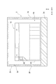
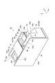
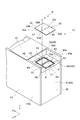
- FIG. 2 is a schematic cross-sectional view taken along the line II-II in FIG. It is a perspective view of the battery pack shown by FIG. It is a side view of the battery pack shown by FIG.
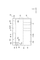
- FIG. 2 is a top view of the battery pack shown in FIG. 1.
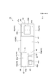
- FIG. 2 is a partially exploded perspective view of the battery pack shown in FIG. 1. It is a schematic diagram which shows the state which the extension part deform
- the battery pack according to this embodiment is mounted on a vehicle.
- the vehicle is, for example, an industrial vehicle.
- An example of the industrial vehicle is a forklift that performs a cargo handling operation.
- a reach lift is illustrated as an example of a forklift.
- FIG. 1 is a side view showing a reach lift.
- the reach lift 1 includes a vehicle body 2, a cargo handling device 3, and a cab 4.
- the reach lift 1 is a compact forklift that a driver stands and operates.
- the body 2 of the reach lift 1 is smaller than the body of the counter-type forklift.
- the size of the vehicle body 2 in the front-rear direction is relatively small.
- “front”, “rear”, “left”, and “right” may indicate directions when the direction from the cab 4 toward the cargo handling device 3 is the “front” direction.
- “upper” and “lower” may indicate a vertically upward direction and a vertically downward direction, respectively.
- the vehicle body 2 includes a pedestal portion 2a and a main body portion 2b.
- the pedestal portion 2 a is disposed at the lower part of the vehicle body 2.
- the pedestal portion 2a has a rectangular parallelepiped shape, for example.
- a rear wheel (drive wheel and steering wheel) 2c and a caster wheel (not shown) are provided in the lower rear portion of the pedestal portion 2a.
- the rear right part on the upper surface of the pedestal part 2a is a floor on which the driver stands.
- the main body 2b is disposed on the top of the pedestal 2a.
- the main body 2b is substantially L-shaped in plan view.
- the inside of the main body 2b is a storage space (battery storage portion) Hs for various devices.
- the front portion of the accommodation space Hs is a space that extends over substantially the entire region of the reach lift 1 in the left-right direction (vehicle width direction).
- the rear portion of the accommodation space Hs is a space that extends over a substantially left half region of the reach lift 1 in the left-right direction.
- a traveling motor 2d and a cargo handling motor 2e are disposed on the upper side of the rear portion of the accommodation space Hs.
- the traveling motor 2d is a motor that is a drive source of the drive wheels.
- the cargo handling motor 2 e is a motor that is a drive source of the cargo handling device 3.
- FIG. 2 is a schematic cross-sectional view taken along the line II-II in FIG.
- the battery pack 10 is accommodated in the front portion of the accommodation space Hs.
- the left side surface 2s of the vehicle body 2 is provided with a lid 2h that can be opened and closed with respect to an opening 2p for inserting the battery pack 10 into the accommodation space Hs.
- the opening 2p is also used as a charging opening for accessing a charging connector 80 described later when the battery pack 10 is charged.
- the battery pack 10 serves as a power source for the traveling motor 2d and the cargo handling motor 2e.
- the battery pack 10 is housed in the housing space Hs so that a side surface 45 provided with a charging connector 80 to be described later is in front of the side surface 2s.
- the cargo handling device 3 includes a pair of left and right reach legs 3a, a fork 3b, and a mast 3c.
- the reach leg 3a is provided forward from the front end of the pedestal 2a.
- a front wheel 3d is provided at the lower front part of each reach leg 3a.
- the mast 3c is erected in front of the main body 2b.
- the mast 3c is attached to a pair of left and right reach legs 3a so as to be movable in the front-rear direction.
- the mast 3c is movable in the front-rear direction along a pair of left and right reach legs 3a by a driving force of a reach cylinder (not shown).
- the fork 3b is attached to the mast 3c via a lift bracket 3e.
- the fork 3b is a member for supporting the load A.
- the fork 3b is movable in the vertical direction along the mast 3c by a driving force of a lift cylinder (not shown) coupled to the mast 3c.
- a vacant space on the right side of the rear part of the vehicle body 2 is the floor.
- the cab 4 is provided with a handle 4a on the left side of the floor.
- FIG. 3 is a perspective view of the battery pack shown in FIG.
- FIG. 4 is a side view of the battery pack shown in FIG.
- FIG. 5 is a top view of the battery pack shown in FIG. 6 is a partially exploded perspective view of the battery pack shown in FIG.
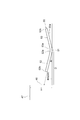
- FIG. 7 is a schematic diagram showing a state in which the extending portion is deformed.
- the words “upper” and “lower” will continue to be used. However, depending on the attitude of the battery pack 10, it may not match “upper” and “lower” (that is, vertically upward and vertically downward) in FIG. .
- the battery pack 10 includes a plurality of battery modules 20, a control unit 30, a housing 40, a lid 50, a first connector 60 (external part), and a second.
- a connector 70 (external part) and a charging connector 80 are provided.
- the control unit 30 controls at least the battery module 20.
- the housing 40 houses the battery module 20 and the control unit 30.
- the lid 50 is attached to the housing 40.
- the first connector 60 is used for connecting the battery module 20 to the outside.
- the second connector 70 is used to connect the control unit 30 to the outside.
- the charging connector 80 is electrically connected to the battery module 20.
- the external component is a component exposed to the outside of the battery pack 10 and may be included in the battery pack 10 or may not be included in the battery pack 10. Examples of the external parts include a connector used for connection to the outside of the battery pack 10, a harness connected to the connector, a control lamp, and the like.
- the battery module 20 includes, for example, a plurality (for example, 7 to 13) of battery cells 21 connected in series with each other.
- the battery cell 21 is a nonaqueous electrolyte secondary battery such as a lithium ion secondary battery.
- the battery modules 20 are connected in parallel to each other by, for example, being integrated and connected to the positive and negative bus bars in a terminal block (not shown).
- the control unit 30 includes, for example, a monitoring ECU (Electronic Control Unit) for monitoring the temperature or voltage of the battery module 20, and electronic components such as an FET relay.
- the control unit 30 can control charging / discharging of the battery module 20 according to the temperature and voltage of the battery module 20 or according to a request from the reach lift 1 side.
- the housing 40 has a generally rectangular parallelepiped outer shape as a whole.
- the housing 40 includes a rectangular parallelepiped first accommodating portion 41 that accommodates the battery module 20, and a rectangular parallelepiped second accommodating portion 42 that accommodates the control unit 30, the terminal block, and the like.
- the first accommodating portion 41 includes a pair of flat side wall portions 43 facing each other, an upper surface 44 (third side surface), a side surface 45 (second side surface), and a side surface 46.
- the battery module 20 is fixed to the side wall 43, for example.
- the upper surface 44 is rectangular.
- the upper surface 44 connects the side wall portions 43 to each other in the short direction of the upper surface 44 (here, the Y-axis direction).
- the side surface 45 and the side surface 46 are substantially parallel to each other and face opposite sides in the longitudinal direction of the upper surface 44 (here, the X-axis direction).
- the side surface 45 and the side surface 46 extend along a direction intersecting (orthogonal) the upper surface 44 from the upper surface 44 (here, the Z-axis direction).
- the upper surface 44 is located below the upper end portion of the side wall portion 43. Therefore, the upper end portion of the side wall portion 43 is a flat plate-like protruding portion 43 p protruding from the upper surface 44.
- the side surface 45 is formed with a notch portion 45p that is notched on the upper surface 44 side and one side wall portion 43 side.
- the bottom surface 45b of the notch 45p is substantially parallel to the side surface 45.
- the bottom surface 45b is connected to the side surface 45 by an inclined surface 45s inclined with respect to the bottom surface 45b.
- the side surface 45 faces the side opposite to the other side surface 48 described later in the longitudinal direction of the upper surface 44.
- the second accommodating portion 42 is provided on the upper surface 44 between the pair of side wall portions 43.
- the second housing part 42 protrudes from the upper surface 44.
- the second accommodating portion 42 is provided in a part of the upper surface 44 in the longitudinal direction. More specifically, the second accommodating portion 42 is provided in the central portion excluding both end portions in the longitudinal direction of the upper surface 44.
- the second housing portion 42 includes an upper surface 47 (first side surface) substantially parallel to the upper surface 44 of the first housing portion 41 and a pair of side surfaces 48 substantially parallel to the side surface 45.
- the upper surface 47 is, for example, coincident with the upper end of the protruding portion 43p. Therefore, the position of the upper surface 44 of the first housing part 41 is lower than the position of the upper surface 47 of the second housing part 42 by the height of the second housing part 42 (height of the side surface 48).
- the upper surface 47 defines the outer shape of the housing 40. More specifically, the upper surface 47 is the top surface of the housing 40.
- the upper surface 44 includes a region 44a and a region 44b located on both ends in the longitudinal direction of the upper surface 44 with the second accommodating portion 42 interposed therebetween.
- the region 44 a is located on the side surface 45 side with respect to the second housing portion 42.
- the region 44b is located closer to the side surface 46 than the second housing portion 42.
- the region 44a is surrounded in three directions by the inner surfaces 43s of the pair of projecting portions 43p and the one side surface 48 of the second housing portion 42.
- the region 44b is surrounded in three directions by the inner surfaces 43s of the pair of projecting portions 43p and the other side surface 48 of the second housing portion 42.
- the regions 44 a and 44 b are the bottom surfaces of the recesses 40 a and 40 b provided on the upper surface 47. That is, the recess 40 a (second recess) is recessed toward the inside of the housing 40.
- the recess 40a has a region 44a as a bottom surface.
- the recess 40a has an inner surface 43s and one side surface 48 as inner walls.
- One side surface 48 connects the region 44 a and the upper surface 47.
- the inner surface 43s extends along a direction (here, the X-axis direction) intersecting (orthogonal) with one side surface 48.
- the recess 40 b (first recess) is recessed toward the inside of the housing 40.
- the recess 40b has a region 44b as a bottom surface.
- the recess 40b has an inner surface 43s and the other side surface 48 as inner walls.
- the other side surface 48 connects the region 44 b and the upper surface 47.
- the inner surface 43s extends along a direction intersecting (orthogonal) with the other side surface 48 (here, the X-axis direction).
- the second accommodating portion 42 and the pair of projecting portions 43p are wall portions erected on the upper surface 44.
- the 2nd accommodating part 42 has a pair of side surface 48 as a side surface of the wall part.
- Each protrusion 43p has an inner surface 43s as a side surface of the wall portion.
- openings A1 and A2 are provided in the region 44b.
- the openings A1 and A2 have a rectangular shape with the same shape.
- the openings A1 and A2 are juxtaposed in the longitudinal direction of the upper surface 44.
- Opening A1 is arrange
- the opening A2 is disposed on the side surface 46 side.
- the region 44b has a peripheral edge R that forms the periphery of the openings A1 and A2.
- the peripheral portion R includes peripheral portions R1 to R3, a pair of peripheral portions R4, and a pair of peripheral portions R5.
- the peripheral edge portion R1 is located between the opening A1 and the opening A2.
- the peripheral edge portion R1 extends along the short side direction of the upper surface 44.
- the peripheral portion R1 is provided with a plurality of screw holes H1 aligned in the Y-axis direction.
- the plurality of screw holes H1 are used to fix the lid 50 to the peripheral portion R1 with the bolt B.
- the peripheral portion R2 faces the peripheral portion R1 in the X-axis direction with the opening A1 interposed therebetween.
- the peripheral portion R2 extends along the Y-axis direction.
- the peripheral edge portion R2 is located between the opening A1 and the other side surface 48 as viewed from the Z-axis direction.
- the peripheral portion R3 is opposed to the peripheral portion R1 in the X-axis direction with the opening A2 interposed therebetween.
- the peripheral portion R3 extends along the Y-axis direction.
- the peripheral edge portion R3 is located between the opening A2 and the side surface 46 when viewed from the Z-axis direction.
- the pair of peripheral edge portions R4 face each other in the Y-axis direction with the opening A1 interposed therebetween.
- Each peripheral portion R4 extends along the X-axis direction.
- the pair of peripheral edge portions R5 face each other in the Y-axis direction with the opening A2 interposed therebetween.
- Each peripheral portion R5 extends along the X-axis direction.
- the lid 50 is made of a general steel material such as SS400 or SPHC.
- the lid 50 is formed of, for example, a rectangular plate having a thickness of 5 mm.
- the thickness and rigidity of the lid 50 are smaller than the thickness and rigidity of each part of the housing 40.
- the lid 50 is disposed on the region 44b and closes the openings A1 and A2.
- the lid 50 has an inner surface 50a that faces the peripheral edge R in the Z-axis direction.
- the lid 50 has a fixed portion 51 and extending portions 52 and 53.
- the fixing part 51 is a part fixed to the housing 40.
- the fixing portion 51 extends along the Y-axis direction at the center of the lid 50 in the X-axis direction.
- the fixed portion 51 is provided with a plurality of through holes H2 aligned in the Y-axis direction.
- the plurality of through holes H2 are provided at positions overlapping the plurality of screw holes H1 when viewed from the Z-axis direction.
- the fixing portion 51 faces the peripheral portion R1 and is fixed to the peripheral portion R1 with a bolt B. That is, the peripheral portion R1 functions as a fixed portion to which the lid 50 is fixed.
- the bolt B is inserted through the through hole H2 and fastened to the screw hole H1.
- the extended portion 52 is a portion that extends from the fixed portion 51 to the peripheral portions R2 and R4 of the peripheral portion R and closes the opening A1.
- the extending part 52 has one end 52a connected to the fixed part 51 and the other end 52b located on the opposite side of the one end 52a in the X-axis direction. In a state where the extension portion 52 closes the opening A1 (a state where the extension portion 52 is not deformed), the other end 52b faces the other side surface 48 in the X-axis direction.
- the extending part 52 is not fixed to the housing 40.
- the extension portion 52 is deformed (for example, elastically deformed (hereinafter the same)) so as to be separated from the peripheral portions R2 and R4 with the fixing portion 51 as a starting point in response to an increase in pressure in the housing 40.
- the opening A1 is opened. To open the opening A1 is to make the inside of the housing 40 communicate with the outside of the housing 40 through the opening A1.
- the extended portion 53 is a portion that extends from the fixed portion 51 to the peripheral portions R3 and R5 of the peripheral portion R and closes the opening A2.
- the extending portion 53 has one end 53a connected to the fixed portion 51 and the other end 53b located on the opposite side of the one end 53a in the X-axis direction.
- the extending part 53 is not fixed to the housing 40. For this reason, the extending part 53 opens the opening A2 by being deformed so as to be separated from the peripheral edge parts R3 and R5 with the fixing part 51 as a starting point in accordance with an increase in the pressure in the housing 40.
- the lid 50 opens the openings A1 and A2 by the deformation of the extending parts 52 and 53.
- the lid body 50 functions as a so-called safety valve, and prevents the pressure in the housing 40 from exceeding a specified pressure.
- This specified pressure is set lower than the pressure at which the housing 40 is damaged when the pressure in the housing 40 increases.
- the lid 50 is formed of a thin plate having lower rigidity than the other parts of the housing 40 as described above in order to ensure the ease of deformation of the extending portions 52 and 53.
- a seal member S is disposed between the peripheral edge R and the lid body 50. Specifically, the seal member S is disposed between the peripheral edge portions R 2 to R 5 and the inner surface 50 a of the lid body 50.
- the seal member S has, for example, a long shape, and is arranged in a rectangular ring shape so as to surround the openings A1 and A2 together with the peripheral edge portion R1.
- the sealing member S for example, polyurethane sponge, EPDM (ethylene / propylene / diene rubber) sponge or the like can be used.
- the seal member S is pressed against the peripheral portions R2 to R5 by the elastic force of the lid 50 in a state where the lid 50 closes the openings A1 and A2, and is compressed by the peripheral portions R2 to R5 and the lid 50. ing. As a result, the seal member S is elastically deformed to exhibit a sealing property, and closes between the peripheral portions R2 to R5 and the lid 50.
- the sealing property referred to here is a property of hermetically sealing the member to be sealed.
- the first connector 60 and the second connector 70 are provided in the recess 40a (a space surrounded by the inner surface 43s and the one side surface 48 on the region 44a).
- the first connector 60 is provided in the region 44a.
- a harness (external component) connected to a connector (not shown) on the reach lift 1 side is connected to the first connector 60.
- the first connector 60 electrically connects the battery module 20 to the travel motor 2d and the cargo handling motor 2e of the reach lift 1.
- the extra length of a harness (not shown) connected to the first connector 60 is routed in the recess 40a.
- the second connector 70 is provided on one side surface 48.
- a signal line (external part) connected to a connector (not shown) on the reach lift 1 side is connected to the second connector 70.
- the second connector 70 electrically connects the control unit 30 to a control unit (not shown) on the reach lift 1 side.
- the extra length of a signal line (not shown) connected to the second connector 70 is routed in the recess 40a.
- the charging connector 80 is provided on the side surface 45. More specifically, the charging connector 80 protrudes from the bottom surface 45b of the cutout 45p of the side surface 45. The front end portion of the charging connector 80 is located closer to the bottom surface 45b than the surface of the side surface 45 other than the notch 45p. Therefore, the charging connector 80 is located inside the entire outer shape of the housing 40.
- the charging connector 80 is electrically connected to the battery module 20 in the first housing portion 41. More specifically, the charging connector 80 is connected to the positive and negative bus bars of the terminal block in the first housing portion 41 using, for example, bolts.
- a communication hole (not shown) that communicates with a connection portion (for example, the bus bar of the terminal block) between the battery module 20 and the charging connector 80 in the first housing portion 41 is formed.
- a flat cover 49 that closes the communication hole is provided in the region 44a. Therefore, for example, when the charging connector 80 is replaced, the connecting portion can be accessed through the communication hole with the cover 49 removed.
- the first connector 60, the second connector 70, and the communication hole are all provided in the recess 40a.
- the first connector 60 and the like are provided on one side of the housing 40 in the longitudinal direction of the upper surface 44.
- the concave portion 40a provided with the first connector 60 and the like is disposed on the left side surface 2s side of the vehicle body 2.
- the extending portions 52 and 53 of the lid 50 are separated from the peripheral portions R2 to R5 with the fixing portion 51 as a starting point in response to an increase in the pressure in the housing 40.
- the openings A1 and A2 provided in the region 44b of the upper surface 44 are opened.
- the lid 50 functions as a so-called safety valve that prevents the pressure in the housing 40 from rising abnormally.
- the gas discharged from the inside of the housing 40 to the outside flows out in a direction spreading around the openings A1 and A2 from the gap between the peripheral edge portions R2 to R5 and the extending portions 52 and 53.
- the region 44b in which the openings A1 and A2 are provided is the bottom surface of the recess 40b provided in the upper surface 47. For this reason, it is possible to control the flow of the gas discharged from the inside of the housing 40 through the openings A1 and A2 to the pair of inner surfaces 43s and the other side surface 48 which are the inner wall surfaces of the recess 40b. .
- the second accommodating portion 42 and the pair of projecting portions 43p are erected as a wall portion on the upper surface 44 provided with the openings A1 and A2.
- the 2nd accommodating part 42 has the side surface 48 as a side surface of a wall part, and each protrusion part 43p has the inner surface 43s as a side surface of a wall part. For this reason, it is possible to control the flow of the gas discharged from the inside of the housing 40 through the openings A1 and A2 to the other side surface 48 and the pair of inner surfaces 43s.
- a charging connector 80 is provided on a side surface 45 (more specifically, a bottom surface 45 b) facing the other side surface 48. Therefore, if the battery pack 10 is accommodated in the accommodation space Hs of the reach lift 1 so that the side surface 45 is on the near side, the charging connector 80 is easily accessed by opening the lid 2h provided in the accommodation space Hs. It becomes possible. At this time, the gas flowing out from the openings A1 and A2 is controlled by the other side surface 48 opposite to the side surface 45 and the pair of inner surfaces 43s, and therefore does not directly reach the opening 2p of the accommodation space Hs. Therefore, the gas flowing out from the openings A1 and A2 is prevented from flowing out directly from the opening 2p of the accommodation space Hs.
- the region 44 a in which the first connector 60 is provided is the bottom surface of the recess 40 a provided in the upper surface 47.
- one side surface 48 provided with the second connector 70 is an inner wall surface of the recess 40a. That is, the first connector 60 and the second connector 70 are provided in the recess 40a. For this reason, the flow of the gas discharged from the openings A1 and A2 provided in the region 44b which is the bottom surface of the recess 40b does not directly hit the first connector 60 and the second connector 70. Thereby, the influence which the gas discharged
- the second housing portion 42 is positioned as a wall portion between the openings A1 and A2 and the first connector 60 and the second connector 70 on the upper surface 44. Yes. For this reason, the flow of gas discharged from the openings A1 and A2 does not directly hit the first connector 60 and the second connector 70. Thereby, the influence which the gas discharged
- the extending portion 52 is deformed so as to be separated from the peripheral portions R2 and R4 with the fixed portion 51 as a starting point. Therefore, in the extension part 52, the other end 52b located on the opposite side of the one end 52a is farther away from the peripheral edge portions R2 and R4 than the one end 52a connected to the fixed part 51. For this reason, the gas in the housing
- the extending portion 53 is deformed so as to be separated from the peripheral portions R3 and R5 with the fixed portion 51 as a starting point. Accordingly, in the extending portion 53, the other end 53b located on the opposite side of the one end 53a is farther away from the peripheral portions R3 and R5 than the one end 53a connected to the fixed portion 51. For this reason, the gas in the housing
- one aspect of the present invention is not limited to the above.
- the above can be arbitrarily changed without changing the gist of each claim.
- the openings A1 and A2 may be provided by being rotated 90 degrees in the region 44b. That is, the openings A ⁇ b> 1 and A ⁇ b> 2 may be arranged in parallel in the short direction of the upper surface 44.
- the lid 50 is also rotated 90 degrees and fixed to the housing 40.
- the other end 52b of the extending portion 52 and the other end 53b of the extending portion 53 are opposed to the inner surface 43s. Therefore, the flow of gas flowing out from the inside of the housing 40 surely hits the inner surface 43s. For this reason, the flow of the gas flowing out from the inside of the housing 40 can be reliably controlled.
- the concave portion 40a includes inner surfaces 43s of a pair of projecting portions 43p and one side surface 48 of the second accommodating portion 42 as three inner wall surfaces. ing.
- the recess 40a only needs to have at least one inner wall surface.
- the recess 40b has inner surfaces 43s of a pair of projecting portions 43p and the other side surface 48 of the second accommodating portion 42 as three inner wall surfaces.
- the recess 40b only needs to have at least one inner wall surface.
- the housing 40 includes the second accommodating portion 42 and the pair of projecting portions 43p as three wall portions erected on the upper surface 44. However, at least one wall portion is provided. It only has to have.
- the battery pack 10 it is sufficient that at least one opening A1, A2 is provided.
- the battery pack 10 only needs to include at least one extending portion 52, 53.
- the first connector 60, the second connector 70, and the charging connector 80 may be provided on the outer surface 43a of the side wall 43, the region 44a of the upper surface 44, the side surface 45, the side surface 46, or the upper surface 47, for example.
Landscapes
- Chemical & Material Sciences (AREA)
- Chemical Kinetics & Catalysis (AREA)
- Electrochemistry (AREA)
- General Chemical & Material Sciences (AREA)
- Battery Mounting, Suspending (AREA)
- Sealing Battery Cases Or Jackets (AREA)
- Gas Exhaust Devices For Batteries (AREA)
Abstract
電池モジュールと、電池モジュールを収容する筐体と、筐体に設けられた開口を閉塞する板状の蓋体と、を備え、蓋体は、筐体に固定された固定部と、固定部から開口の周縁部に至るように延在する延在部と、を有し、延在部は、筐体内の圧力の上昇に応じて、固定部を起点として周縁部から離間するように変形することにより開口を開放し、筐体は、筐体の内部に向かって凹む第1凹部が設けられた第1側面を有し、第1凹部は、底面と、底面と第1側面とを接続する内壁面と、を有し、開口は、底面に設けられている、電池パック。
Description
本発明の一側面は、電池パックに関する。
特許文献1には、電池モジュールを収容するケースを有する電池パックが記載されている。特許文献1に記載の電池パックのケースには、ケース内と外部とを連通させる貫通孔が設けられている。この貫通孔には、ケース内の圧力が規定圧力を超えると破断することで貫通孔を開放する圧力開放弁が設けられている。圧力開放弁は、ケース内の圧力が異常に上昇することを防ぐ、いわゆる安全弁として機能する。
電池パックは、例えば、バッテリーとして車両のバッテリー収容部に収容される。上述の電池パックでは、圧力開放弁が破断した際に、貫通孔を通じてケース内から外部に排出されるガスの流れを制御(規制)することができない。このため、ケース内からの噴出ガスが、バッテリー収容部に設けられた、例えば充電用の開口から直接外部に流出してしまうおそれがある。
本発明の一側面は、筐体内から外部に排出されるガスの流れを制御可能な電池パックを提供する。
本発明の一側面に係る電池パックは、電池モジュールと、電池モジュールを収容する筐体と、筐体に設けられた開口を閉塞する板状の蓋体と、を備えている。蓋体は、筐体に固定された固定部と、固定部から開口の周縁部に至るように延在する延在部と、を有している。延在部は、筐体内の圧力の上昇に応じて、固定部を起点として周縁部から離間するように変形することにより開口を開放する。筐体は、筐体の内部に向かって凹む第1凹部が設けられた第1側面を有している。第1凹部は、底面と、底面と第1側面とを接続する内壁面と、を有している。開口は、底面に設けられている。
この電池パックでは、蓋体の延在部は、筐体内の圧力の上昇に応じて、固定部を起点として周縁部から離間するように変形することにより、開口を開放する。これにより、蓋体は、筐体内の圧力が異常に上昇することを防ぐ、いわゆる安全弁として機能する。筐体内から外部に排出されるガスは、周縁部と延在部との間の隙間から開口の周囲に広がる方向に流出する。開口は、筐体の第1側面に設けられた第1凹部の底面に設けられている。このため、筐体内から開口を介して外部に排出されるガスの流れを、第1凹部の内壁面に当てることによって制御することができる。
本発明の一側面に係る電池パックにおいては、筐体は、内壁面と反対側に臨む第2側面を有していてもよい。第2側面には、充電コネクタが設けられていてもよい。この場合、充電コネクタが第2側面に設けられている。したがって、その第2側面が手前側になるように電池パックを車両のバッテリー収容部に収容すれば、バッテリー収容部に設けられた開口から充電コネクタにアクセスすることが可能となる。このとき、第1側面の開口から流出するガスは、第2側面の反対側の内壁面によって制御されるので、充電用の開口に直接至らない。したがって、第1側面の開口から流出するガスが、充電用の開口から直接外部に流出することが抑制される。
本発明の一側面に係る電池パックにおいては、第1側面には、筐体の内部に向かって凹む第2凹部が設けられていてもよい。第2凹部内には、外部部品が設けられていてもよい。この場合、外部部品が第2凹部内に設けられているので、第1凹部の底面に設けられた開口から排出されるガスの流れが直接外部部品に当たることがない。これにより、筐体内から排出されるガスが外部部品に与える影響を抑制することができる。外部部品として、電池モジュールに接続されるコネクタ、及び、電池モジュールの制御を行う制御部に接続されるコネクタ等が挙げられる。
本発明の一側面に係る電池パックにおいては、延在部は、固定部と接続された一端と、一端の反対側に位置する他端とを有していてもよい。他端は、内壁面と対向していてもよい。この場合、延在部は固定部を起点として周縁部から離間するように変形する。したがって、延在部では、固定部と接続された一端よりも、一端の反対側に位置する他端の方が、周縁部から大きく離間する。このため、筐体内のガスは延在部の他端側から流出し易い。延在部の他端は、第1凹部の内壁面と対向している。したがって、筐体内から流出するガスの流れが確実に内壁面に当たることになる。このため、筐体内から流出するガスの流れを確実に制御することができる。
本発明の一側面に係る電池パックは、電池モジュールと、電池モジュールを収容する筐体と、筐体に設けられた開口を閉塞する板状の蓋体と、を備えている。蓋体は、筐体に固定された固定部と、固定部から開口の周縁部に至るように延在する延在部と、を有している。延在部は、筐体内の圧力の上昇に応じて、固定部を起点として周縁部から離間するように変形することにより開口を開放する。筐体は、開口が設けられた第3側面と、第3側面に立設された壁部と、を有する。
この電池パックでは、蓋体の延在部は、筐体内の圧力の上昇に応じて、固定部を起点として周縁部から離間するように変形することにより、開口を開放する。これにより、蓋体は、筐体内の圧力が異常に上昇することを防ぐ、いわゆる安全弁として機能する。筐体内から外部に排出されるガスは、周縁部と延在部との間の隙間から開口の周囲に広がる方向に流出する。開口は、筐体の第3側面に設けられ、第3側面には壁部が立設されている。このため、筐体内から開口を介して外部に排出されるガスの流れを、壁部に当てることによって制御することができる。
本発明の一側面によれば、筐体内から流出するガスの流れを制御可能な電池パックを提供することができる。
以下、添付図面を参照しながら本発明の一側面の実施形態を詳細に説明する。図面の説明において、同一または同等の要素には同一符号が用いられ、重複する説明は省略される。
本実施形態に係る電池パックは、車両に搭載される。車両は、例えば産業車両である。産業車両としては、一例として、荷役作業を行うフォークリフトが挙げられる。ここでは、フォークリフトの一例として、リーチリフトを例示する。図1は、リーチリフトを示す側面図である。図1に示されるように、リーチリフト1は、車体2、荷役装置3、及び、運転室4を備えている。リーチリフト1は、運転者が立って操作するコンパクトなフォークリフトである。
そのため、リーチリフト1の車体2は、カウンタタイプのフォークリフトの車体と比べると小さい。特に、車体2の前後方向における寸法が、相対的に小さい。以下の説明における「前」、「後」、「左」、及び、「右」は、運転室4から荷役装置3に向かう方向を「前」方向としたときの各方向を示す場合がある。以下の説明における「上」及び「下」は、それぞれ、鉛直上方及び鉛直下方を示す場合がある。
車体2は、台座部2aと本体部2bとを含む。台座部2aは、車体2の下部に配置されている。台座部2aは、例えば直方体形状である。台座部2aの後方下部には、後輪(駆動輪、及び、操舵輪)2cとキャスタホイール(不図示)とが設けられている。台座部2aの上面における後方右部は、運転者が立つフロアとされている。
本体部2bは、台座部2aの上部に配置されている。本体部2bは、平面視において、略L字形状である。本体部2bの内部は、各種機器の収容スペース(バッテリー収容部)Hsとなっている。収容スペースHsの前部は、リーチリフト1の左右方向(車幅方向)の略全領域に広がるスペースである。収容スペースHsの後部は、リーチリフト1の左右方向の略左半分の領域に広がるスペースである。収容スペースHsの後部における上側には、走行用モータ2dと荷役用モータ2eが配置されている。走行用モータ2dは、駆動輪の駆動源となるモータである。荷役用モータ2eは、荷役装置3の駆動源となるモータである。
図2は、図1のII-II線に沿っての模式断面図である。図2に示されるように、収容スペースHsの前部には、電池パック10が収容されている。車体2の左側の側面2sには、収容スペースHsに電池パック10を挿入するための開口2pに対して蓋体2hが開閉可能に設けられている。ここでは、開口2pは、電池パック10を充電する際に、後述の充電コネクタ80にアクセスするための充電用の開口としても用いられる。電池パック10は、走行用モータ2d及び荷役用モータ2e等の電力源となる。電池パック10は、後述の充電コネクタ80が設けられた側面45が側面2s側から見て手前となるように、収容スペースHsに収容されている。
図1に示されるように、荷役装置3は、左右一対のリーチレグ3a、フォーク3b、及びマスト3cを有している。リーチレグ3aは、台座部2aの前端部から前方に向かって設けられている。各リーチレグ3aの前方下部には、前輪3dが設けられている。マスト3cは、本体部2bの前方に立設されている。マスト3cは、左右一対のリーチレグ3aに前後方向に移動自在に取り付けられている。マスト3cは、リーチシリンダ(不図示)の駆動力により、左右一対のリーチレグ3aに沿って前後方向に移動可能である。
フォーク3bは、マスト3cにリフトブラケット3eを介して取り付けられている。フォーク3bは、積荷Aを支持するための部材である。フォーク3bは、マスト3cに結合されたリフトシリンダ(不図示)の駆動力により、マスト3cに沿って上下方向に移動可能である。運転室4においては、車体2の後部の右側の空いているスペースが上記のフロアとされている。運転室4には、フロアの左側においてハンドル4aが設けられている。
続いて、図3~図7を参照して、実施形態に係る電池パック10について説明する。図3は、図1に示される電池パックの斜視図である。図4は、図1に示される電池パックの側面図である。図5は、図1に示される電池パックの上面図である。図6は、図1に示される電池パックの一部分解斜視図である。図7は、延在部が変形した状態を示す模式図である。以下では、引き続き「上」及び「下」の語句を使用するが、電池パック10の姿勢によっては、図1における「上」及び「下」(すなわち鉛直上方及び鉛直下方)と一致しない場合がある。
図3~図5に示されるように、電池パック10は、複数の電池モジュール20と、制御部30と、筐体40と、蓋体50と、第1コネクタ60(外部部品)と、第2コネクタ70(外部部品)と、充電コネクタ80と、を備えている。制御部30は、少なくとも電池モジュール20の制御を行う。筐体40は、電池モジュール20及び制御部30を収容する。蓋体50は、筐体40に取り付けられる。第1コネクタ60は、電池モジュール20を外部に接続するために用いられる。第2コネクタ70は、制御部30を外部に接続するために用いられる。充電コネクタ80は、電池モジュール20に電気的に接続されている。外部部品とは、電池パック10の外部に露出した部品であって、電池パック10に含まれるものであってもよいし、電池パック10に含まれないものであってもよい。外部部品として、電池パック10の外部との接続に用いられるコネクタ、そのコネクタに接続されるハーネス、及び制御用ランプ等が挙げられる。
電池モジュール20は、例えば、互いに直列に接続された複数(例えば7~13)の電池セル21を有している。電池セル21は、例えばリチウムイオン二次電池などの非水電解質二次電池である。電池モジュール20は、例えば、端子台(不図示)において、正極側及び負極側のそれぞれのバスバーに集約されて接続されることにより、互いに並列に接続されている。
制御部30は、例えば、電池モジュール20の温度又は電圧を監視するための監視ECU(Electronic Control Unit)、及びFETリレー等の電子部品を含む。制御部30は、例えば、電池モジュール20の温度及び電圧に応じて、或いはリーチリフト1側からの要求に応じて、電池モジュール20の充放電を制御することができる。
筐体40は、全体として概ね直方体状の外形を有している。筐体40は、電池モジュール20を収容する直方体状の第1収容部41と、制御部30及び端子台等を収容する直方体状の第2収容部42と、を有する。第1収容部41は、互いに対向する一対の平板状の側壁部43と、上面44(第3側面)と、側面45(第2側面)と、側面46と、を含む。電池モジュール20は、例えば、側壁部43に固定されている。
上面44は、長方形状である。上面44は、上面44の短手方向(ここではY軸方向)において、側壁部43同士を接続している。側面45及び側面46は、互いに略平行であり、上面44の長手方向(ここではX軸方向)において互いに反対側を臨む。側面45及び側面46は、上面44から上面44に交差(直交)する方向(ここではZ軸方向)に沿って延在している。
上面44は、側壁部43の上端部よりも下方に位置している。したがって、側壁部43の上端部は、上面44から突出する平板状の突出部43pとなっている。側面45には、上面44側及び一方の側壁部43側に切り欠けた切欠き部45pが形成されている。切欠き部45pの底面45bは、側面45と略平行である。底面45bは、底面45bに対して傾斜する傾斜面45sによって、側面45に接続されている。側面45は、上面44の長手方向において、後述の他方の側面48と反対側に臨んでいる。
第2収容部42は、一対の側壁部43の間において上面44に設けられている。第2収容部42は、上面44から突出している。第2収容部42は、上面44の長手方向における一部分に設けられている。より具体的には、第2収容部42は、上面44の長手方向における両端部を除いた中央部に設けられている。第2収容部42は、第1収容部41の上面44と略平行な上面47(第1側面)と、側面45と略平行な一対の側面48と、を含む。
上面47は、例えば、突出部43pの上端と一致している。したがって、第1収容部41の上面44の位置は、第2収容部42の高さ(側面48の高さ)の分だけ、第2収容部42の上面47の位置よりも低くなっている。上面47は、筐体40の外形を規定する。より具体的には、上面47は、筐体40の頂面である。
上面44は、第2収容部42を挟んで上面44の長手方向の両端側に位置する領域44a及び領域44bを含んでいる。領域44aは、第2収容部42よりも側面45側に位置している。領域44bは、第2収容部42よりも側面46側に位置している。領域44aは、一対の突出部43pの内面43sと、第2収容部42における一方の側面48と、によって3方向に囲われている。領域44bは、一対の突出部43pの内面43sと、第2収容部42における他方の側面48と、によって3方向に囲われている。
筐体40の頂面である上面47を基準に考えると、領域44a,44bは、上面47に設けられた凹部40a,40bの底面である。すなわち、凹部40a(第2凹部)は、筐体40の内部に向かって凹んでいる。凹部40aは、底面として領域44aを有する。凹部40aは、内壁面として内面43s及び一方の側面48を有する。一方の側面48は、領域44aと上面47とを接続している。内面43sは、一方の側面48に交差(直交)する方向(ここではX軸方向)に沿って延在している。凹部40b(第1凹部)は、筐体40の内部に向かって凹んでいる。凹部40bは、底面として領域44bを有する。凹部40bは、内壁面として内面43s及び他方の側面48を有する。他方の側面48は、領域44bと上面47とを接続している。内面43sは、他方の側面48に交差(直交)する方向(ここではX軸方向)に沿って延在している。
上面44を基準に考えると、第2収容部42及び一対の突出部43pは、上面44に立設された壁部である。第2収容部42は、その壁部の側面として一対の側面48を有する。各突出部43pは、その壁部の側面として内面43sを有する。
図6に示されるように、領域44bには、開口A1,A2が設けられている。開口A1,A2は、互いに同形状をなす矩形状を呈している。開口A1,A2は、上面44の長手方向に並設されている。開口A1は、第2収容部42側に配置されている。開口A2は、側面46側に配置されている。領域44bは、開口A1,A2の周縁をなす周縁部Rを有している。
周縁部Rは、周縁部分R1~R3と、一対の周縁部分R4と、一対の周縁部分R5と、を含んでいる。周縁部分R1は、開口A1と開口A2との間に位置している。周縁部分R1は、上面44の短手方向に沿って延びている。周縁部分R1には、複数のネジ孔H1がY軸方向に並んで設けられている。複数のネジ孔H1は、蓋体50をボルトBにより周縁部分R1に固定するために用いられる。周縁部分R2は、開口A1を挟んで周縁部分R1とX軸方向において対向している。周縁部分R2は、Y軸方向に沿って延びている。周縁部分R2は、Z軸方向から見て、開口A1と他方の側面48との間に位置している。
周縁部分R3は、開口A2を挟んで周縁部分R1とX軸方向において対向している。周縁部分R3は、Y軸方向に沿って延びている。周縁部分R3は、Z軸方向から見て、開口A2と側面46との間に位置している。一対の周縁部分R4は、開口A1を挟んでY軸方向において互いに対向している。各周縁部分R4は、X軸方向に沿って延びている。一対の周縁部分R5は、開口A2を挟んでY軸方向において互いに対向している。各周縁部分R5は、X軸方向に沿って延びている。
蓋体50は、例えば、SS400及びSPHC等の一般的な鋼材により形成されている。蓋体50は、例えば、厚さが5mmの矩形状の板材により形成されている。蓋体50の厚さ及び剛性は、筐体40の各部の厚さ及び剛性よりも小さい。蓋体50は、領域44b上に配置され、開口A1,A2を閉塞している。蓋体50は、周縁部RとZ軸方向において対向する内面50aを有している。
蓋体50は、固定部51と、延在部52,53と、を有している。固定部51は、筐体40に固定される部分である。固定部51は、蓋体50のX軸方向の中央部において、Y軸方向に沿って延在している。固定部51には、複数の貫通孔H2がY軸方向に並んで設けられている。複数の貫通孔H2は、複数のネジ孔H1とZ軸方向から見て重なる位置に設けられている。固定部51は、周縁部分R1と対向し、ボルトBにより、周縁部分R1に固定されている。すなわち、周縁部分R1は蓋体50が固定される被固定部として機能している。ボルトBは、貫通孔H2に挿通され、かつ、ネジ孔H1に締結される。
延在部52は、固定部51を起点として周縁部Rの周縁部分R2,R4に至るように延在し、開口A1を閉塞する部分である。延在部52は、固定部51と接続された一端52aと、X軸方向において一端52aの反対側に位置する他端52bと、を有している。延在部52が開口A1を閉塞している状態(延在部52が変形していない状態)において、他端52bは、他方の側面48とX軸方向において対向している。延在部52は、筐体40に固定されていない。このため、延在部52は、筐体40内の圧力の上昇に応じて、固定部51を起点として周縁部分R2,R4から離間するように変形(例えば弾性変形(以下同様))することにより、開口A1を開放する。開口A1を開放するとは、筐体40の内部と筐体40の外部とを開口A1を通じて連通させることである。
延在部53は、固定部51を起点として周縁部Rの周縁部分R3,R5に至るように延在し、開口A2を閉塞する部分である。延在部53は、固定部51と接続された一端53aと、X軸方向において一端53aの反対側に位置する他端53bと、を有している。延在部53は、筐体40に固定されていない。このため、延在部53は、筐体40内の圧力の上昇に応じて、固定部51を起点として周縁部分R3,R5から離間するように変形することにより、開口A2を開放する。
すなわち、蓋体50は、延在部52,53の変形により開口A1,A2を開放する。これにより、蓋体50は、いわゆる安全弁として機能し、筐体40内の圧力が規定圧力を超えることを防止している。この規定圧力は、筐体40内の圧力が高まることにより、筐体40が破損する圧力よりも低く設定されている。蓋体50は、延在部52,53の変形のし易さを確保するため、上述したように筐体40の他の部分に比べて剛性の低い薄板で形成されている。
図7に示されるように、延在部52が変形した状態において、延在部52が領域44bに対して成す角度をθとし、固定部51から他方の側面48までの距離をDとし、他方の側面48の高さ(領域44bから上面47までの距離)をHとする。筐体40内のガスは延在部52に沿って外部に流出しようとする。このため、ガスの流れを他方の側面48に当てるには、tanθ≦H/Dとなるように、これらのパラメータが適宜調整されればよい。
図6に示されるように、周縁部Rと蓋体50との間には、シール部材Sが配置されている。具体的には、シール部材Sは、周縁部分R2~R5と蓋体50の内面50aとの間に配置されている。シール部材Sは、例えば長尺状を呈し、開口A1,A2を周縁部分R1ごとまとめて取り囲むように、矩形環状に配置されている。シール部材Sとして、例えばポリウレタンスポンジ、又はEPDM(エチレン・プロピレン・ジエンゴム)スポンジ等を用いることができる。
シール部材Sは、蓋体50が開口A1,A2を閉塞している状態において、蓋体50の弾性力により周縁部分R2~R5に押し付けられ、周縁部分R2~R5と蓋体50とにより圧縮されている。この結果、シール部材Sは、弾性変形してシール性を発揮し、周縁部分R2~R5と蓋体50との間を塞いでいる。ここで言うシール性とは、シール対象部材を気密に封止する性質である。
図3~図5に示されるように、第1コネクタ60及び第2コネクタ70は、凹部40a内(領域44a上において内面43sと一方の側面48とによって囲われたスペース)に設けられている。具体的には、第1コネクタ60は、領域44aに設けられている。第1コネクタ60には、例えば、リーチリフト1側のコネクタ(不図示)に接続されるハーネス(外部部品)が接続される。これにより、第1コネクタ60は、例えば、電池モジュール20をリーチリフト1の走行用モータ2d及び荷役用モータ2e等に電気的に接続する。第1コネクタ60に接続されたハーネス(不図示)の余長は、凹部40a内に取り回される。
第2コネクタ70は、一方の側面48に設けられている。第2コネクタ70には、例えば、リーチリフト1側のコネクタ(不図示)に接続される信号線(外部部品)が接続される。これにより、第2コネクタ70は、例えば、制御部30をリーチリフト1側の制御部(不図示)に電気的に接続する。第2コネクタ70に接続された信号線(不図示)の余長は、凹部40a内に取り回される。
充電コネクタ80は、側面45に設けられている。より具体的には、充電コネクタ80は、側面45の切欠き45pの底面45bに突設されている。充電コネクタ80の先端部は、側面45の切欠き45p以外の面よりも底面45b側に位置している。したがって、充電コネクタ80は、筐体40の全体の外形の内側に位置している。充電コネクタ80は、第1収容部41内において、電池モジュール20に電気的に接続されている。より具体的には、充電コネクタ80は、第1収容部41内において、端子台の正負のバスバーに対して、例えばボルト等を用いて接続されている。
領域44aには、第1収容部41内における電池モジュール20と充電コネクタ80との接続部(例えば上記の端子台のバスバー)に連通する連通孔(不図示)が形成されている。領域44aには、この連通孔を塞ぐ平板状のカバー49が設けられている。したがって、例えば充電コネクタ80を交換する際には、カバー49を外した状態において、連通孔を介して接続部にアクセス可能である。
ここで、第1コネクタ60、第2コネクタ70、及び、連通孔は、いずれも凹部40a内に設けられている。換言すれば、第1コネクタ60等は、上面44の長手方向において筐体40の一方側に偏って設けられている。電池パック10をリーチリフト1の収容スペースHsに収容するときには、この第1コネクタ60等が設けられた凹部40aを車体2の左側の側面2s側に配置する。電池パック10がこのように収容されることで、蓋体2hを開くことにより、車体2の左側において、第1コネクタ60等に対する作業を容易に行うことが可能である。
以上説明したように、電池パック10においては、蓋体50の延在部52,53は、筐体40内の圧力の上昇に応じて、固定部51を起点として周縁部分R2~R5から離間するように変形することにより、上面44の領域44bに設けられた開口A1,A2を開放する。これにより、蓋体50は、筐体40内の圧力が異常に上昇することを防ぐ、いわゆる安全弁として機能する。筐体40内から外部に排出されるガスは、周縁部分R2~R5と延在部52,53との間の隙間から開口A1,A2の周囲に広がる方向に流出する。
筐体40の頂面である上面47を基準に考えると、開口A1,A2が設けられた領域44bは、上面47に設けられた凹部40bの底面である。このため、筐体40内から開口A1,A2を介して外部に排出されるガスの流れを、凹部40bの内壁面である一対の内面43s及び他方の側面48に当てることによって制御することができる。
筐体40の上面44を基準に考えると、開口A1,A2が設けられた上面44には、第2収容部42及び一対の突出部43pが壁部として立設されている。第2収容部42は、壁部の側面として側面48を有し、各突出部43pは、壁部の側面として内面43sを有する。このため、筐体40内から開口A1,A2を介して外部に排出されるガスの流れを、他方の側面48及び一対の内面43sに当てることによって制御することができる。
筐体40では、他方の側面48と反対側に臨む側面45(より具体的には、底面45b)に充電コネクタ80が設けられている。したがって、側面45が手前側になるように電池パック10をリーチリフト1の収容スペースHsに収容すれば、収容スペースHsに設けられた蓋体2hを開けることにより、充電コネクタ80に容易にアクセスすることが可能となる。このとき、開口A1,A2から流出するガスは、側面45と反対側の他方の側面48、及び一対の内面43sによって制御されるので、収容スペースHsの開口2pに直接至らない。したがって、開口A1,A2から流出するガスが、収容スペースHsの開口2pから直接外部に流出することが抑制される。
筐体40の頂面である上面47を基準に考えると、第1コネクタ60が設けられた領域44aは、上面47に設けられた凹部40aの底面である。更に、第2コネクタ70が設けられた一方の側面48は、凹部40aの内壁面である。つまり、第1コネクタ60及び第2コネクタ70は、凹部40a内に設けられている。このため、凹部40bの底面である領域44bに設けられた開口A1,A2から排出されるガスの流れが第1コネクタ60及び第2コネクタ70に直接当たることがない。これにより、筐体40内から排出されるガスが第1コネクタ60及び第2コネクタ70に与える影響を抑制することができる。
筐体40の上面44を基準に考えると、上面44上において、開口A1,A2と、第1コネクタ60及び第2コネクタ70との間には、壁部として第2収容部42が位置している。このため、開口A1,A2から排出されるガスの流れが第1コネクタ60及び第2コネクタ70に直接当たることがない。これにより、筐体40内から排出されるガスが第1コネクタ60及び第2コネクタ70に与える影響を抑制することができる。
延在部52は固定部51を起点として周縁部分R2,R4から離間するように変形する。したがって、延在部52では、固定部51と接続された一端52aよりも、一端52aの反対側に位置する他端52bの方が、周縁部分R2,R4から大きく離間する。このため、筐体40内のガスは他端52b側から流出し易い。他端52bは、他方の側面48と対向しているので、筐体40内から流出するガスの流れが確実に他方の側面48に当たることになる。このため、筐体40内から流出するガスの流れを確実に制御することができる。
延在部53は固定部51を起点として周縁部分R3,R5から離間するように変形する。したがって、延在部53では、固定部51と接続された一端53aよりも、一端53aの反対側に位置する他端53bの方が、周縁部分R3,R5から大きく離間する。このため、筐体40内のガスは他端53b側から流出し易い。他端53b側から流出するガスの流れは、側面46に向かうことになる。したがって、側面46が奥側になるように電池パック10をリーチリフト1の収容スペースHsに収容すれば、他端53b側から流出するガスの流れが、収容スペースHsの開口2pに直接至ることはない。開口A2から側面46に向かう方向には、筐体40内から排出されるガスにより影響を受けるような外部部品が設けられていない。
以上の実施形態は、本発明の一側面について説明したものである。したがって、本発明の一側面は、上記のものに限定されない。本発明の一側面は、各請求項の要旨を変更しない範囲において、上記のものを任意に変更したものとすることができる。
開口A1,A2が、領域44bにおいて、90度回転して設けられていてもよい。すなわち、開口A1,A2が、上面44の短手方向に並設されていてもよい。この場合、蓋体50も90度回転して筐体40に固定される。延在部52の他端52b及び延在部53の他端53bはそれぞれ内面43sと対向している。したがって、筐体40内から流出するガスの流れが確実に内面43sに当たることになる。このため、筐体40内から流出するガスの流れを確実に制御することができる。
筐体40の頂面である上面47を基準に考えると、凹部40aは、3つの内壁面として一対の突出部43pの内面43sと、第2収容部42における一方の側面48と、を有している。凹部40aは、少なくとも1つ以上の内壁面を有していればよい。凹部40bは、3つの内壁面として一対の突出部43pの内面43sと、第2収容部42における他方の側面48と、を有している。凹部40bは、少なくとも1つ以上の内壁面を有していればよい。
上面44を基準に考えると、筐体40は、上面44に立設された3つの壁部として、第2収容部42及び一対の突出部43pを有しているが、少なくとも1つの壁部を有していればよい。
電池パック10では、開口A1,A2が少なくとも一つ設けられていればよい。電池パック10は、延在部52,53を少なくとも一つ備えていればよい。
第1コネクタ60、第2コネクタ70、及び充電コネクタ80は、例えば、側壁部43の外面43a、上面44の領域44a、側面45、側面46、又は上面47に設けられていてもよい。
10…電池パック、20…電池モジュール、40…筐体、40a…凹部(第2凹部)、40b…凹部(第1凹部)、42…第2収容部(壁部)、43p…突出部(壁部)、43s…内面(内壁面)、44…上面(第3側面)、44b…領域(底面)、45…側面(第2側面)、47…上面(第1側面)、48…側面(内壁面)、50…蓋体、51…固定部、52,53…延在部、52a,53a…一端、52b、53b…他端、60…第1コネクタ、70…第2コネクタ、80…充電コネクタ、A1,A2…開口、R…周縁部、R1~R5…周縁部分。
Claims (5)
- 電池モジュールと、
前記電池モジュールを収容する筐体と、
前記筐体に設けられた開口を閉塞する板状の蓋体と、を備え、
前記蓋体は、前記筐体に固定された固定部と、前記固定部から前記開口の周縁部に至るように延在する延在部と、を有し、
前記延在部は、前記筐体内の圧力の上昇に応じて、前記固定部を起点として前記周縁部から離間するように変形することにより前記開口を開放し、
前記筐体は、前記筐体の内部に向かって凹む第1凹部が設けられた第1側面を有し、
前記第1凹部は、底面と、前記底面と前記第1側面とを接続する内壁面と、を有し、
前記開口は、前記底面に設けられている、電池パック。 - 前記筐体は、前記内壁面と反対側に臨む第2側面を有し、
前記第2側面には、充電コネクタが設けられている、請求項1に記載の電池パック。 - 前記第1側面には、前記筐体の内部に向かって凹む第2凹部が設けられ、
前記第2凹部内には、外部部品が設けられている、請求項1又は2に記載の電池パック。 - 前記延在部は、前記固定部と接続された一端と、前記一端の反対側に位置する他端とを有し、
前記他端は、前記内壁面と対向している、請求項1~3のいずれか一項に記載の電池パック。 - 電池モジュールと、
前記電池モジュールを収容する筐体と、
前記筐体に設けられた開口を閉塞する板状の蓋体と、を備え、
前記蓋体は、前記筐体に固定された固定部と、前記固定部から前記開口の周縁部に至るように延在する延在部と、を有し、
前記延在部は、前記筐体内の圧力の上昇に応じて、前記固定部を起点として前記周縁部から離間するように変形することにより前記開口を開放し、
前記筐体は、前記開口が設けられた第3側面と、前記第3側面に立設された壁部と、を有する、電池パック。
Applications Claiming Priority (2)
| Application Number | Priority Date | Filing Date | Title |
|---|---|---|---|
| JP2016147258A JP6620695B2 (ja) | 2016-07-27 | 2016-07-27 | 電池パック |
| JP2016-147258 | 2016-07-27 |
Publications (1)
| Publication Number | Publication Date |
|---|---|
| WO2018020747A1 true WO2018020747A1 (ja) | 2018-02-01 |
Family
ID=61015854
Family Applications (1)
| Application Number | Title | Priority Date | Filing Date |
|---|---|---|---|
| PCT/JP2017/014401 Ceased WO2018020747A1 (ja) | 2016-07-27 | 2017-04-06 | 電池パック |
Country Status (2)
| Country | Link |
|---|---|
| JP (1) | JP6620695B2 (ja) |
| WO (1) | WO2018020747A1 (ja) |
Families Citing this family (1)
| Publication number | Priority date | Publication date | Assignee | Title |
|---|---|---|---|---|
| JP7591726B2 (ja) * | 2020-09-25 | 2024-11-29 | パナソニックIpマネジメント株式会社 | バッテリケースおよび電動アシスト自転車用バッテリ |
Citations (3)
| Publication number | Priority date | Publication date | Assignee | Title |
|---|---|---|---|---|
| JP2011054420A (ja) * | 2009-09-02 | 2011-03-17 | Nissan Motor Co Ltd | 電池モジュール、組電池、および電池モジュールの製造方法 |
| JP2014017270A (ja) * | 2010-03-18 | 2014-01-30 | Mitsubishi Motors Corp | バッテリケース及び電池パック |
| WO2014041970A1 (ja) * | 2012-09-14 | 2014-03-20 | 日産自動車株式会社 | 車載用バッテリパックの圧力開放構造 |
-
2016
- 2016-07-27 JP JP2016147258A patent/JP6620695B2/ja active Active
-
2017
- 2017-04-06 WO PCT/JP2017/014401 patent/WO2018020747A1/ja not_active Ceased
Patent Citations (3)
| Publication number | Priority date | Publication date | Assignee | Title |
|---|---|---|---|---|
| JP2011054420A (ja) * | 2009-09-02 | 2011-03-17 | Nissan Motor Co Ltd | 電池モジュール、組電池、および電池モジュールの製造方法 |
| JP2014017270A (ja) * | 2010-03-18 | 2014-01-30 | Mitsubishi Motors Corp | バッテリケース及び電池パック |
| WO2014041970A1 (ja) * | 2012-09-14 | 2014-03-20 | 日産自動車株式会社 | 車載用バッテリパックの圧力開放構造 |
Also Published As
| Publication number | Publication date |
|---|---|
| JP2018018659A (ja) | 2018-02-01 |
| JP6620695B2 (ja) | 2019-12-18 |
Similar Documents
| Publication | Publication Date | Title |
|---|---|---|
| US11367882B2 (en) | Mount structure of fuel cell stack | |
| US9893333B2 (en) | Battery block and secondary battery module | |
| JP4386131B2 (ja) | 電気自動車 | |
| US12128750B2 (en) | Energy store-floor assembly for a motor vehicle | |
| US10062929B2 (en) | Battery unit | |
| EP3650321B1 (en) | A vehicle battery arrangement | |
| KR20140042737A (ko) | 조전지 | |
| KR20250165570A (ko) | 배터리 팩 | |
| JP6724518B2 (ja) | 電池パック及び電池パックの重量調整方法 | |
| US11450874B2 (en) | Fuel cell unit | |
| JP6620695B2 (ja) | 電池パック | |
| JP6780375B2 (ja) | 電池モジュール | |
| JP7224193B2 (ja) | 電池構造物固定構造 | |
| JP5895072B2 (ja) | 車両の接続部配置構造 | |
| JP6784101B2 (ja) | 電池パックの配置構造 | |
| JP6615703B2 (ja) | 基板収容ケース、電装ユニット及び作業機 | |
| JP7435034B2 (ja) | リチウムイオンバッテリ搭載車両 | |
| JP6724504B2 (ja) | 電池パック、及び、車両 | |
| JP6794767B2 (ja) | 電池パック | |
| JP6572692B2 (ja) | 電池パック | |
| US20250174801A1 (en) | On-board structure for battery packs | |
| US20250266554A1 (en) | Power storage device and vehicle | |
| KR20260027060A (ko) | 축전 장치 및 차량 | |
| JP2025125285A (ja) | 蓄電装置および車両 | |
| WO2023188990A1 (ja) | 作業車両用バッテリ及び作業車両 |
Legal Events
| Date | Code | Title | Description |
|---|---|---|---|
| 121 | Ep: the epo has been informed by wipo that ep was designated in this application |
Ref document number: 17833758 Country of ref document: EP Kind code of ref document: A1 |
|
| NENP | Non-entry into the national phase |
Ref country code: DE |
|
| 122 | Ep: pct application non-entry in european phase |
Ref document number: 17833758 Country of ref document: EP Kind code of ref document: A1 |