WO2018020557A1 - 分配器及び冷凍サイクル装置 - Google Patents
分配器及び冷凍サイクル装置 Download PDFInfo
- Publication number
- WO2018020557A1 WO2018020557A1 PCT/JP2016/071766 JP2016071766W WO2018020557A1 WO 2018020557 A1 WO2018020557 A1 WO 2018020557A1 JP 2016071766 W JP2016071766 W JP 2016071766W WO 2018020557 A1 WO2018020557 A1 WO 2018020557A1
- Authority
- WO
- WIPO (PCT)
- Prior art keywords
- return
- header
- pipe
- fluid
- distributor
- Prior art date
Links
- 238000005057 refrigeration Methods 0.000 title claims description 26
- 239000012530 fluid Substances 0.000 claims abstract description 107
- XLYOFNOQVPJJNP-UHFFFAOYSA-N water Substances O XLYOFNOQVPJJNP-UHFFFAOYSA-N 0.000 description 32
- 239000003507 refrigerant Substances 0.000 description 5
- 238000010438 heat treatment Methods 0.000 description 4
- 238000004378 air conditioning Methods 0.000 description 3
- 230000002528 anti-freeze Effects 0.000 description 2
- 238000010586 diagram Methods 0.000 description 2
- 239000000470 constituent Substances 0.000 description 1
- 238000009434 installation Methods 0.000 description 1
- 239000007788 liquid Substances 0.000 description 1
Images

Classifications
-
- F—MECHANICAL ENGINEERING; LIGHTING; HEATING; WEAPONS; BLASTING
- F24—HEATING; RANGES; VENTILATING
- F24D—DOMESTIC- OR SPACE-HEATING SYSTEMS, e.g. CENTRAL HEATING SYSTEMS; DOMESTIC HOT-WATER SUPPLY SYSTEMS; ELEMENTS OR COMPONENTS THEREFOR
- F24D3/00—Hot-water central heating systems
- F24D3/18—Hot-water central heating systems using heat pumps
-
- F—MECHANICAL ENGINEERING; LIGHTING; HEATING; WEAPONS; BLASTING
- F24—HEATING; RANGES; VENTILATING
- F24D—DOMESTIC- OR SPACE-HEATING SYSTEMS, e.g. CENTRAL HEATING SYSTEMS; DOMESTIC HOT-WATER SUPPLY SYSTEMS; ELEMENTS OR COMPONENTS THEREFOR
- F24D3/00—Hot-water central heating systems
- F24D3/10—Feed-line arrangements, e.g. providing for heat-accumulator tanks, expansion tanks ; Hydraulic components of a central heating system
- F24D3/1058—Feed-line arrangements, e.g. providing for heat-accumulator tanks, expansion tanks ; Hydraulic components of a central heating system disposition of pipes and pipe connections
- F24D3/1066—Distributors for heating liquids
-
- F—MECHANICAL ENGINEERING; LIGHTING; HEATING; WEAPONS; BLASTING
- F25—REFRIGERATION OR COOLING; COMBINED HEATING AND REFRIGERATION SYSTEMS; HEAT PUMP SYSTEMS; MANUFACTURE OR STORAGE OF ICE; LIQUEFACTION SOLIDIFICATION OF GASES
- F25B—REFRIGERATION MACHINES, PLANTS OR SYSTEMS; COMBINED HEATING AND REFRIGERATION SYSTEMS; HEAT PUMP SYSTEMS
- F25B41/00—Fluid-circulation arrangements
-
- Y—GENERAL TAGGING OF NEW TECHNOLOGICAL DEVELOPMENTS; GENERAL TAGGING OF CROSS-SECTIONAL TECHNOLOGIES SPANNING OVER SEVERAL SECTIONS OF THE IPC; TECHNICAL SUBJECTS COVERED BY FORMER USPC CROSS-REFERENCE ART COLLECTIONS [XRACs] AND DIGESTS
- Y02—TECHNOLOGIES OR APPLICATIONS FOR MITIGATION OR ADAPTATION AGAINST CLIMATE CHANGE
- Y02B—CLIMATE CHANGE MITIGATION TECHNOLOGIES RELATED TO BUILDINGS, e.g. HOUSING, HOUSE APPLIANCES OR RELATED END-USER APPLICATIONS
- Y02B30/00—Energy efficient heating, ventilation or air conditioning [HVAC]
- Y02B30/12—Hot water central heating systems using heat pumps
Definitions
- the present invention relates to a distributor that distributes a fluid to a plurality of units, and a refrigeration cycle apparatus including the distributor.
- Such a refrigeration cycle apparatus is used as an air conditioner or a water heater.
- a plurality of indoor units are connected to one outdoor unit, and a distributor (header) for distributing and circulating a fluid from the outdoor unit side to the indoor unit side is provided.
- a hot water heating header as described in Patent Document 1 has been proposed.
- the header for hot water heating described in Patent Document 1 includes a hot water supply pipe header to which a hot water supply pipe (outward piping) for supplying hot water to a load equipment (indoor unit) is connected, and hot water used in the load equipment. And a hot water return header to which a hot water return pipe (return pipe) returning to the heat source machine (hot water storage tank) is connected.
- a hot water supply pipe header to which a hot water supply pipe (outward piping) for supplying hot water to a load equipment (indoor unit) is connected, and hot water used in the load equipment.
- a hot water return header to which a hot water return pipe (return pipe) returning to the heat source machine (hot water storage tank) is connected.
- the warm water heating header described in Patent Document 1 has a double-pipe structure of a warm water supply header and a warm water return header, and has a circuit configuration that bypasses each other by forming a bypass hole in the warm water supply header. ing.
- Patent Document 1 when the inner diameter of the bypass hole is equal to or larger than the diameter of the outlet, the fluid may short cycle even on the heat source side.
- Patent Document 1 since the warm water supply header and the warm water return header have a double pipe structure, the fluid flowing through the warm water supply header and the fluid flowing through the warm water return header exchange heat. As a result, the heat exchange efficiency is also reduced.
- the present invention has been made against the background of the above problems, and an object of the present invention is to provide a distributor in which a short cycle of fluid does not occur, and a refrigeration cycle apparatus including the distributor. .
- the distributor according to the present invention has a forward header to which a plurality of forward pipes are connected, and a return header to which a plurality of return pipes are connected. Including at least two first forward pipes connected to the fluid distribution side and one second forward pipe connected to the fluid supply side, wherein the plurality of return pipes are connected to the fluid distribution side. At least two first return pipes connected to the fluid supply side, and one second return pipe connected to the fluid supply side, wherein the second return pipe includes at least two of the first return pipes.
- the downstream side of the flow direction of the fluid returning from the return pipe, and the connection position of the return side header of at least two of the first return pipes is connected to the opposite side in the longitudinal direction of the return side header Is.
- a refrigeration cycle apparatus includes a heat source unit, a plurality of load side units, and the distributor connected between the heat source unit and the plurality of load side units. .
- the second return pipe is downstream in the flow direction of the fluid returning from the at least two first return pipes, and the return header of the at least two first return pipes Since the connection position is connected to the opposite side of the longitudinal direction of the return header, the flow of fluid is not hindered in the return header, and a short cycle of fluid does not occur in the circuit on the fluid distribution side.
- the refrigeration cycle apparatus uses the distributor described above, there is no occurrence of a fluid short cycle in the circuit on the fluid distribution side, and there is no reduction in efficiency due to the fluid short cycle. .
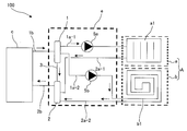
- FIG. 1 is a perspective view showing a configuration example of a distributor e according to Embodiment 1 of the present invention.
- the distributor e will be described with reference to FIG.
- the distributor e is connected between at least one outdoor unit constituting a refrigeration cycle apparatus such as an air conditioner and a plurality of indoor units, and distributes the fluid to each of the plurality of indoor units. It is.
- the outdoor unit side that is a heat source unit is referred to as a fluid supply side
- the indoor unit side that is a load device is referred to as a fluid distribution side.
- the distributor e has a forward header 1 for distributing the fluid and a return header 2 for joining the fluid.
- the forward header 1 and the return header 2 are arranged so that, for example, the fluid flow direction, that is, the longitudinal direction is parallel.
- the forward header 1 and the return header 2 are connected by a bypass pipe 3.
- the bypass pipe 3 connects one end side of the outgoing header 1 and one end side of the return header 2. That is, the bypass pipe 3 connects the forward header 1 and the return header 2 on the side surface on the right end side of the drawing.
- the bypass pipe 3 extends linearly and connects the facing positions of the forward header 1 and the return header 2.
- the bypass pipe 3 is configured so that the inner diameter is smaller than both the forward pipe connected to the forward header 1 and the inner diameter of the return pipe connected to the return header 2. By doing so, the flow of fluid in the bypass pipe 3 can be made harder than the flow of fluid in the forward pipe. By doing so, it is possible to reduce the short cycle of the fluid on the fluid supply side and the reverse flow of the fluid on the fluid distribution side.
- a plurality of outgoing pipes are connected to the outgoing header 1.
- at least two forward pipes connected to the fluid distribution side are referred to as a first forward pipe 1a-1 and a first forward pipe 1a-2.
- at least one forward pipe connected to the fluid supply side is referred to as a second forward pipe 1b.
- the first forward pipe 1 a-1 and the first forward pipe 1 a-2 are arranged in parallel with the forward header 1.
- the second forward pipe 1b is on the side facing the first forward pipe 1a-1 and the first forward pipe 1a-2, and the connection position of the first forward pipe 1a-1 and the first forward pipe 1a-2. It is connected between the connection position.
- connection position of the second forward pipe 1b is the first forward pipe 1a-1 and the side where the second forward pipe 1b faces the first forward pipe 1a-1 and the first forward pipe 1a-2. It means that it is located on the opposite side to the connection position of the first forward pipe 1a-2.
- a pump 5a for circulating a fluid is installed in the first forward pipe 1a-1.
- a pump 5b for circulating a fluid is installed in the first forward pipe 1a-2.
- a plurality of return pipes are connected to the return side header 2.
- at least two return pipes connected to the fluid distribution side are referred to as a first return pipe 2a-1 and a first return pipe 2a-2.
- at least one return pipe connected to the fluid supply side is referred to as a second return pipe 2b.
- the first return pipe 2 a-1 and the first return pipe 2 a-2 are arranged in parallel to the return side header 2.
- the second return pipe 2b is connected to a position facing the first return pipe 2a-1 and the first return pipe 2a-2 on the side facing the first return pipe 2a-1 and the first return pipe 2a-2.
- connection position of the second return pipe 2b and the side where the second return pipe 2b faces the first return pipe 2a-1 and the first return pipe 2a-2 are the first return pipe 2a-1 and the first return pipe 2a-1. It means that it is located on the opposite side to the connection position of the first return pipe 2a-2.
- the pump 5a may be installed in the first return pipe 2a-1 instead of the first forward pipe 1a-1
- the pump 5b is installed in the first return pipe 2a-2 instead of the first forward pipe 1a-2. May be installed.
- the distributor e branches the fluid into two is shown as an example, but the number of branches of the fluid is not particularly limited.
- the second return pipe 2b is positioned closest to the forward header 1 relative to the connection position of the other return pipe, that is, the fluid returning from the first return pipe. What is necessary is just to connect with the connection position of the return side header 2 of the 1st return piping to the other side of the longitudinal direction of the return side header 2 downstream in the flow direction. By doing so, the flow of fluid in the return header 2 is not hindered.
- connection position of the return pipe (second return pipe 2b) connected to the fluid supply side at the return header 2 is the return pipe (first pipe connected to the fluid distribution side).
- 1 return pipe 2a-1, first return pipe 2a-2) is closer to the forward header 1 than the connection position at the return header 2 of the first return pipe 2a-2). No short fluid cycle occurs in the circuit.
- the distance between the forward header 1 and the return header 2 can be shortened, which contributes to the miniaturization of the distributor e. Further, by configuring the distributor e as described above, parts such as a check valve are not necessary, and a simple circuit configuration can be realized. Therefore, according to the divider
- FIG. FIG. 2 is a circuit configuration diagram schematically showing an example of the circuit configuration of the refrigeration cycle apparatus 100 according to Embodiment 2 of the present invention.
- the refrigeration cycle apparatus 100 will be described with reference to FIG.
- an air conditioner will be described as an example of the refrigeration cycle apparatus 100.
- the flow of a fluid such as a refrigerant or water is indicated by an arrow.
- fluid such as refrigerant or water supplied from the heat source device c to the distributor e is collectively referred to as fluid.
- the refrigeration cycle apparatus 100 includes the distributor e according to Embodiment 1 described above as one of its components. Specifically, as shown in FIG. 1, the refrigeration cycle apparatus 100 includes one heat source machine c, a plurality of load side machines A (load side machine a and load side machine b), a distributor e, ,have.
- FIG. 1 shows an example in which the number of heat source devices c is one, but the number of heat source devices c is not particularly limited, and a plurality of heat source devices c are connected in series or in parallel to the distributor e. You may make it provide.
- FIG. 1 shows an example in which the load side machine A and the load side machine b are connected as the load side machine A, but three or more load side machines are connected to the distributor e. May be connected in parallel.
- the heat source unit c is used as, for example, an outdoor unit or an outdoor unit according to the use of the refrigeration cycle apparatus 100, and supplies a heat source to the load side unit A via a fluid.
- This heat source device c is the fluid supply side described in the first embodiment.
- the heat source device c houses a compressor, an expansion device, a heat source side heat exchanger, a blower, and the like.
- the heat source is stored in a refrigerant that is a fluid and is supplied from the heat source unit c to the load side unit A.
- another heat exchanger may be provided in the heat source machine c in addition to the heat source side heat exchanger, and the heat source may be indirectly supplied to the load side machine A.
- the heat source is stored in water as a fluid and supplied to the load side machine A. That is, the heat source stored in the refrigerant by the heat source device c may be transmitted to another fluid such as water via another heat exchanger, and this fluid may be supplied to the load side device A.
- a pump that circulates water or antifreeze liquid is accommodated in the heat source device c as a heat medium transport device instead of a blower.
- the load-side unit A is used as, for example, an indoor unit, an indoor unit, or a hot water supply unit according to the use of the refrigeration cycle apparatus 100, and is air or a load-side target by a heat source supplied from the heat source unit c via a fluid. Water or the like is heated or cooled.
- the load side machine A is the fluid distribution side described in the first embodiment.
- the load side machine A accommodates a load side heat exchanger, a blower, and the like. Depending on the mode of the load side heat exchanger, a pump that circulates water or antifreeze instead of a blower is accommodated in the load side machine A as a heat transfer device.
- the load-side heat exchanger accommodated in the load-side machine a is referred to as a load-side heat exchanger a1
- the load-side heat exchanger accommodated in the load-side machine b is referred to as a load-side heat exchanger b1.
- the load side machine A will be referred to as a load side machine A.
- the distributor e is connected between the heat source machine c and the load side machine A, and distributes and circulates the fluid supplied from the heat source machine c to each of the load side machines A.
- the configuration of the distributor e is as described in the first embodiment.
- the fluid flowing through the first forward pipe 1a-1 flows into the load-side heat exchanger a1 of the load-side machine a, and the heat medium such as air or water that is the load-side target is exchanged in the load-side heat exchanger a1 by heat exchange. Warm or cool.
- the fluid flowing through the first forward pipe 1a-2 flows into the load-side heat exchanger b1 of the load-side machine b, and in the load-side heat exchanger b1, the heat medium such as air or water that is the load-side target is exchanged by heat exchange. Warm or cool.
- the fluid that exchanges heat with the heat medium in the load side heat exchanger a1 and the load side heat exchanger b1 flows out of the load side machine a and the load side machine b.
- the fluid flowing out from the load side machine a flows through the first return pipe 2a-1 and into the return side header 2 of the distributor e.
- the fluid flowing out from the load side machine b passes through the first return pipe 2a-2 and flows into the return side header 2 of the distributor e.
- the fluids that flow into the return header 2 are merged and returned to the heat source machine c through the second return pipe 2b.
- the fluid returning from the load side machine a flows through the first return pipe 2a-1 and flows into the return side header 2.
- the fluid flowing into the return header 2 is guided to the second return pipe 2b located immediately after the first return pipe 2a-1, that is, on the opposite side of the first return pipe 2a-1. And it will be returned to the heat source machine c. That is, according to the distributor e, the fluid that has flowed into the return header 2 via the first return pipe 2a-1 returns to the heat source unit c via the second return pipe 2b.
- the fluid flows smoothly at, and the fluid does not short cycle in the circuit of the load side machine a.
- the fluid returning from the load side machine b flows through the first return pipe 2a-2 and flows into the return side header 2.
- the fluid flowing into the return header 2 is guided to the second return pipe 2b located on the opposite side of the first return pipe 2a-2. And it will be returned to the heat source machine c. That is, according to the distributor e, the fluid flowing into the return header 2 via the first return pipe 2a-2 also returns to the heat source device c via the second return pipe 2b.
- the fluid flows smoothly at, and the fluid does not short cycle in the circuit of the load side machine a.
- the fluid returning from the load side machine a and the load side machine b flows through the first return pipe 2a-1 and the first return pipe 2a-2, respectively.
- the fluid that has flowed into the return header 2 is merged and guided to the second return pipe 2b located on the opposite side of the first return pipe 2a-1 and the first return pipe 2a-2. And it will be returned to the heat source machine c. Therefore, according to the distributor e, the fluid merged in the return side header 2 smoothly returns to the heat source unit c through the second return pipe 2b, so that the fluid is not hindered in the return side header 2, and the load The fluid does not short cycle in the circuit of the side machine a.
- the fluid supplied from the heat source device c flows into the forward header 1 of the distributor e through the second forward pipe 1b.
- the fluid flowing into the outgoing header 1 is guided to the first outgoing pipe 1a-1. That is, in this case, only the pump 5a is driven and the pump 5b is stopped. Therefore, the fluid flowing into the forward header 1 is guided only to the first forward pipe 1a-1.
- the fluid flowing through the first forward pipe 1a-1 flows into the load-side heat exchanger a1 of the load-side machine a, and the heat medium such as air or water that is the load-side target is exchanged in the load-side heat exchanger a1 by heat exchange. Warm or cool.
- the fluid exchanged with the heat medium in the load side heat exchanger a1 flows out of the load side machine a.
- the fluid flowing out from the load side machine a flows through the first return pipe 2a-1 and into the return side header 2 of the distributor e.
- the fluid flowing into the return header 2 is returned to the heat source machine c through the second return pipe 2b.
- connection position of the second return pipe 2b is the first return pipe 2a-1 and the first return pipe 2a. Since the position is closer to the forward header 1 than the connection position of -2, it is possible to prevent the backflow of fluid to the unused load side machine.
- the load side machine b is a load side machine which is frequently used and frequently opens and closes the circuit
- the usage frequency of the load side machine A is set when the refrigeration cycle apparatus 100 is installed.
- the high usage frequency means that it is assumed in advance that the usage frequency increases according to the use of each connected load-side unit.
- the usage of the load side machine includes air conditioning in a living room, air conditioning in a warehouse, air conditioning in a common space, floor heating, hot water supply and the like.
- the first return pipe 2 a-2 connecting the load side machine “b” and the return side header 2 is connected to a position farthest from the second return pipe 2 b in the return side header 2.
- the distributor e since the distributor e is provided as a configuration, a short cycle can be performed in a circuit on the load side unit with a simple piping configuration that does not require components such as a check valve. It can be prevented from generating. Further, according to the refrigeration cycle apparatus 100, since the inner diameter of the bypass pipe 3 is smaller than the inner diameter of the forward header 1 and the return header 2, a short cycle of fluid is generated in the circuit on the load side. You can avoid it. Furthermore, according to the refrigeration cycle apparatus 100, since the second return pipe 2b is connected to the position closest to the heat source device c side, the load side device side can be connected even during operation when the entire load side device is not used. There is no fluid backflow into the circuit.
Abstract
本発明に係る分配器は、複数本の往き配管が接続されている往き側ヘッダーと、複数本の戻り配管が接続されている戻り側ヘッダーと、を有し、前記複数本の往き配管は、流体分配側に接続されている少なくとも2本の第1往き配管と、流体供給側に接続されている1本の第2往き配管と、を含み、前記複数本の戻り配管は、前記流体分配側に接続されている少なくとも2本の第1戻り配管と、前記流体供給側に接続されている1本の第2戻り配管と、を含み、前記第2戻り配管は、少なくとも2本の前記第1戻り配管から戻ってくる流体の流れ方向下流側であって、少なくとも2本の前記第1戻り配管の前記戻り側ヘッダーの接続位置とは前記戻り側ヘッダーの長手方向の反対側に接続されている。
Description
本発明は、流体を複数のユニットへ分配する分配器、及び、この分配器を備えた冷凍サイクル装置に関するものである。
室外機などのユニットと室内機などのユニットとを備えた冷凍サイクル装置が種々提案されている。このような冷凍サイクル装置は、空気調和装置又は給湯器などとして利用されている。空気調和装置においては、1台の室外機に対して複数台の室内機を接続し、室外機側から室内機側へ流体を分配して循環させるための分配器(ヘッダー)を備えたものが存在する。そのようなものとして、たとえば特許文献1に記載されているような温水暖房用ヘッダーが提案されている。
特許文献1に記載されている温水暖房用ヘッダーは、負荷機器(室内機)へ温水を供給する温水供給管(往き配管)が接続される温水供給管ヘッダーと、負荷機器で使用された温水を熱源機(貯湯槽)へ戻す温水戻し管(戻り配管)が接続される温水戻しヘッダーとを有している。
特許文献1に記載されている温水暖房用ヘッダーは、温水供給用ヘッダーと温水戻し用ヘッダーとを二重管構造とし、温水供給用ヘッダーにバイパス孔を形成し、互いをバイパスする回路構成となっている。
しかしながら、特許文献1の回路構成においては、温水供給用ヘッダーと温水戻し用ヘッダーとが二重管構造となっているので、特に熱源機側の往き戻り口から離れた位置にある負荷機器側の往き戻り口において流体がショートサイクルしてしまう可能性がある。
また、特許文献1の回路構成においては、熱源機側の往き戻り口から離れた位置にある負荷機器側の往き戻り回路の不使用時においても、負荷機器側へ流体が不用意に流入してしまう可能性がある。
また、特許文献1の回路構成においては、熱源機側の往き戻り口から離れた位置にある負荷機器側の往き戻り回路の不使用時においても、負荷機器側へ流体が不用意に流入してしまう可能性がある。
さらに、特許文献1においては、バイパス孔の内径が往き口の径を同等以上である場合、熱源側でも流体がショートサイクルしてしまう可能性がある。
加えて、特許文献1においては、温水供給用ヘッダーと温水戻し用ヘッダーとが二重管構造となっているので、温水供給用ヘッダーとを流れる流体と温水戻し用ヘッダーを流れる流体とが熱交換してしまい、熱交換効率が低減してしまうことにもなる。
加えて、特許文献1においては、温水供給用ヘッダーと温水戻し用ヘッダーとが二重管構造となっているので、温水供給用ヘッダーとを流れる流体と温水戻し用ヘッダーを流れる流体とが熱交換してしまい、熱交換効率が低減してしまうことにもなる。
本発明は、上記のような課題を背景としてなされたものであり、流体のショートサイクルが発生しないようにした分配器、及び、この分配器を備えた冷凍サイクル装置を提供することを目的とする。
本発明に係る分配器は、複数本の往き配管が接続されている往き側ヘッダーと、複数本の戻り配管が接続されている戻り側ヘッダーと、を有し、前記複数本の往き配管は、流体分配側に接続されている少なくとも2本の第1往き配管と、流体供給側に接続されている1本の第2往き配管と、を含み、前記複数本の戻り配管は、前記流体分配側に接続されている少なくとも2本の第1戻り配管と、前記流体供給側に接続されている1本の第2戻り配管と、を含み、前記第2戻り配管は、少なくとも2本の前記第1戻り配管から戻ってくる流体の流れ方向下流側であって、少なくとも2本の前記第1戻り配管の前記戻り側ヘッダーの接続位置とは前記戻り側ヘッダーの長手方向の反対側に接続されているものである。
本発明に係る冷凍サイクル装置は、熱源機と、複数台の負荷側機と、前記熱源機と前記複数台の負荷側機との間に接続された上記の分配器と、備えたものである。
本発明に係る分配器によれば、第2戻り配管が少なくとも2本の第1戻り配管から戻ってくる流体の流れ方向下流側であって、少なくとも2本の第1戻り配管の戻り側ヘッダーの接続位置とは戻り側ヘッダーの長手方向の反対側に接続されているので、戻り側ヘッダーにおいて流体の流れが妨げられず、流体分配側の回路内で流体のショートサイクルが発生することがない。
本発明に係る冷凍サイクル装置は、上記の分配器を用いているので、流体分配側の回路内での流体のショートサイクルが発生することがなく、流体のショートサイクルによって効率が低下することがない。
以下、図面を適宜参照しながら本発明の実施の形態について説明する。なお、図1を含め、以下の図面では各構成部材の大きさの関係が実際のものとは異なる場合がある。また、図1を含め、以下の図面において、同一の符号を付したものは、同一又はこれに相当するものであり、このことは明細書の全文において共通することとする。さらに、明細書全文に表わされている構成要素の形態は、あくまでも例示であって、これらの記載に限定されるものではない。
実施の形態1.
図1は、本発明の実施の形態1に係る分配器eの構成例を示す斜視図である。図1に基づいて、分配器eについて説明する。
分配器eは、空気調和装置等の冷凍サイクル装置を構成している少なくとも1台の室外機と複数台の室内機との間に接続され、複数台の室内機のそれぞれへ流体を分配するものである。
なお、以下の説明において、熱源機である室外機側を流体供給側と称し、負荷機器である室内機側を流体分配側と称するものとする。
図1は、本発明の実施の形態1に係る分配器eの構成例を示す斜視図である。図1に基づいて、分配器eについて説明する。
分配器eは、空気調和装置等の冷凍サイクル装置を構成している少なくとも1台の室外機と複数台の室内機との間に接続され、複数台の室内機のそれぞれへ流体を分配するものである。
なお、以下の説明において、熱源機である室外機側を流体供給側と称し、負荷機器である室内機側を流体分配側と称するものとする。
図1に示すように、分配器eは、流体を分配するための往き側ヘッダー1と、流体を合流するための戻り側ヘッダー2と、を有している。往き側ヘッダー1と、戻り側ヘッダー2とは、たとえば流体の流れ方向、つまり長手方向が平行となるように配置されている。また、往き側ヘッダー1と戻り側ヘッダー2とは、バイパス管3で接続されている。
バイパス管3は、往き側ヘッダー1の一方の端部側と戻り側ヘッダー2の一方の端部側とを接続している。つまり、バイパス管3は、往き側ヘッダー1と戻り側ヘッダー2とを紙面右側の端部側の側面で接続している。バイパス管3は、直線的に延び、往き側ヘッダー1及び戻り側ヘッダー2の対面している位置を接続している。バイパス管3は、内径が、往き側ヘッダー1に接続している往き配管、及び、戻り側ヘッダー2に接続している戻り配管の内径のいずれよりも小さく構成されている。こうすることにより、バイパス管3における流体の流れを往き配管における流体の流れよりも流れにくくできる。こうすることにより、流体供給側で流体がショートサイクルしたり、流体分配側で流体が逆流したり、することが低減できる。
往き側ヘッダー1には、複数本の往き配管が接続されている。複数本の往き配管のうち流体分配側に接続される少なくとも2本の往き配管を、第1往き配管1a-1、第1往き配管1a-2と称する。複数本の往き配管のうち流体供給側に接続される少なくとも1本の往き配管を、第2往き配管1bと称する。
第1往き配管1a-1と第1往き配管1a-2とは、往き側ヘッダー1に対して並列に配置されている。一方、第2往き配管1bは、第1往き配管1a-1及び第1往き配管1a-2と対向する側であって、第1往き配管1a-1の接続位置と第1往き配管1a-2の接続位置との間に接続されている。
第1往き配管1a-1と第1往き配管1a-2とは、往き側ヘッダー1に対して並列に配置されている。一方、第2往き配管1bは、第1往き配管1a-1及び第1往き配管1a-2と対向する側であって、第1往き配管1a-1の接続位置と第1往き配管1a-2の接続位置との間に接続されている。
なお、第2往き配管1bと、第1往き配管1a-1及び第1往き配管1a-2とが対向する側とは、第2往き配管1bの接続位置が、第1往き配管1a-1及び第1往き配管1a-2の接続位置と反対側に位置していることを意味している。
また、第1往き配管1a-1には、流体を循環させるポンプ5aが設置されている。同様に、第1往き配管1a-2には、流体を循環させるポンプ5bが設置されている。
また、第1往き配管1a-1には、流体を循環させるポンプ5aが設置されている。同様に、第1往き配管1a-2には、流体を循環させるポンプ5bが設置されている。
戻り側ヘッダー2には、複数本の戻り配管が接続されている。複数本の戻り配管のうち流体分配側に接続される少なくとも2本の戻り配管を、第1戻り配管2a-1、第1戻り配管2a-2と称する。複数本の戻り配管のうち流体供給側に接続される少なくとも1本の戻り配管を、第2戻り配管2bと称する。
第1戻り配管2a-1と第1戻り配管2a-2とは、戻り側ヘッダー2に対して並列に配置されている。一方、第2戻り配管2bは、第1戻り配管2a-1及び第1戻り配管2a-2と対向する側であって、第1戻り配管2a-2と最も離れた位置に接続されている。
第1戻り配管2a-1と第1戻り配管2a-2とは、戻り側ヘッダー2に対して並列に配置されている。一方、第2戻り配管2bは、第1戻り配管2a-1及び第1戻り配管2a-2と対向する側であって、第1戻り配管2a-2と最も離れた位置に接続されている。
なお、第2戻り配管2bと、第1戻り配管2a-1及び第1戻り配管2a-2とが対向する側とは、第2戻り配管2bの接続位置が、第1戻り配管2a-1及び第1戻り配管2a-2の接続位置と反対側に位置していることを意味している。
また、ポンプ5aを第1往き配管1a-1ではなく、第1戻り配管2a-1に設置してもよく、ポンプ5bを第1往き配管1a-2ではなく、第1戻り配管2a-2に設置してもよい。
また、ポンプ5aを第1往き配管1a-1ではなく、第1戻り配管2a-1に設置してもよく、ポンプ5bを第1往き配管1a-2ではなく、第1戻り配管2a-2に設置してもよい。
ここでは、分配器eが流体を2分岐する場合を例に示しているが、流体の分岐数を特に限定するものではない。流体を3分岐以上にする場合であっても、第2戻り配管2bを、他の戻り配管の接続位置よりも往き側ヘッダー1に最も近接した位置、つまり第1戻り配管から戻ってくる流体の流れ方向下流側であって、第1戻り配管の戻り側ヘッダー2の接続位置とは戻り側ヘッダー2の長手方向の反対側に接続すればよい。こうすることで、戻り側ヘッダー2における流体の流れが妨げられないことになる。
以上のように、分配器eによれば、流体供給側に接続される戻り配管(第2戻り配管2b)の戻り側ヘッダー2での接続位置が、流体分配側に接続される戻り配管(第1戻り配管2a-1、第1戻り配管2a-2)の戻り側ヘッダー2での接続位置よりも往き側ヘッダー1に近いので、戻り側ヘッダー2において流体の流れが妨げられず、流体分配側の回路内で流体のショートサイクルが発生することがない。
また、分配器eを以上のような構成とすることで、往き側ヘッダー1及び戻り側ヘッダー2の間の距離を短くすることができ、分配器eの小型化に寄与することになる。また、分配器eを以上のような構成とすることで、逆止弁などの部品が不要となり、シンプルな回路構成が実現できる。そのため、分配器eによれば、省スペースでの設置が可能になる。
実施の形態2.
図2は、本発明の実施の形態2に係る冷凍サイクル装置100の回路構成の一例を概略的に示す回路構成図である。図2に基づいて、冷凍サイクル装置100について説明する。なお、実施の形態2では、冷凍サイクル装置100の一例として空気調和装置を例に説明するものとする。また、図2では、冷媒又は水などの流体の流れを矢印で示している。以下の説明において、熱源機cから分配器eに供給される冷媒又は水などの流体をまとめて流体と称するものとする。
図2は、本発明の実施の形態2に係る冷凍サイクル装置100の回路構成の一例を概略的に示す回路構成図である。図2に基づいて、冷凍サイクル装置100について説明する。なお、実施の形態2では、冷凍サイクル装置100の一例として空気調和装置を例に説明するものとする。また、図2では、冷媒又は水などの流体の流れを矢印で示している。以下の説明において、熱源機cから分配器eに供給される冷媒又は水などの流体をまとめて流体と称するものとする。
<冷凍サイクル装置100の構成>
冷凍サイクル装置100は、上述した実施の形態1に係る分配器eを構成の1つとして備えている。具体的には、図1に示すように、冷凍サイクル装置100は、1台の熱源機cと、複数台の負荷側機A(負荷側機a及び負荷側機b)と、分配器eと、を有している。図1では、熱源機cが1台の場合を例に示しているが、熱源機cの台数を特に限定するものではなく、複数台の熱源機cを分配器eに対して直列又は並列に設けるようにしてもよい。また、図1では、負荷側機Aとして負荷側機a及び負荷側機bの2台が接続されている場合を例に示しているが、3台以上の負荷側機を分配器eに対して並列に接続してもよい。
冷凍サイクル装置100は、上述した実施の形態1に係る分配器eを構成の1つとして備えている。具体的には、図1に示すように、冷凍サイクル装置100は、1台の熱源機cと、複数台の負荷側機A(負荷側機a及び負荷側機b)と、分配器eと、を有している。図1では、熱源機cが1台の場合を例に示しているが、熱源機cの台数を特に限定するものではなく、複数台の熱源機cを分配器eに対して直列又は並列に設けるようにしてもよい。また、図1では、負荷側機Aとして負荷側機a及び負荷側機bの2台が接続されている場合を例に示しているが、3台以上の負荷側機を分配器eに対して並列に接続してもよい。
(熱源機c)
熱源機cは、冷凍サイクル装置100の用途に応じ、たとえば室外機、室外ユニットとして利用され、流体を介して負荷側機Aに熱源を供給するものである。この熱源機cが、実施の形態1で説明した流体供給側である。
熱源機cには、図示してはいないが、圧縮機、絞り装置、熱源側熱交換器、及び、送風機等が収容されている。
熱源機cは、冷凍サイクル装置100の用途に応じ、たとえば室外機、室外ユニットとして利用され、流体を介して負荷側機Aに熱源を供給するものである。この熱源機cが、実施の形態1で説明した流体供給側である。
熱源機cには、図示してはいないが、圧縮機、絞り装置、熱源側熱交換器、及び、送風機等が収容されている。
これらの要素が、負荷側機Aに収容されている負荷側熱交換器と配管接続される場合、これらの要素と負荷側熱交換器とにより冷媒回路が形成される。この場合、熱源が流体である冷媒に蓄えられて熱源機cから負荷側機Aに供給されることになる。
あるいは、熱源機cに、熱源側熱交換器の他に別の熱交換器を設け、熱源を間接的に負荷側機Aに供給するようにしてもよい。この場合、熱源が流体である水などに蓄えられて負荷側機Aに供給されることになる。つまり、熱源機cで冷媒に蓄えられた熱源を、別の熱交換器を介して水等の他の流体に伝達し、この流体を負荷側機Aに供給するようにしてもよい。
あるいは、熱源機cに、熱源側熱交換器の他に別の熱交換器を設け、熱源を間接的に負荷側機Aに供給するようにしてもよい。この場合、熱源が流体である水などに蓄えられて負荷側機Aに供給されることになる。つまり、熱源機cで冷媒に蓄えられた熱源を、別の熱交換器を介して水等の他の流体に伝達し、この流体を負荷側機Aに供給するようにしてもよい。
なお、熱源側熱交換器の態様によっては、送風機ではなく、水又は不凍液を循環させるポンプが熱媒体搬送装置として熱源機cに収容される。
(負荷側機A)
負荷側機Aは、冷凍サイクル装置100の用途に応じ、たとえば室内機、室内ユニット、あるいは、給湯ユニットとして利用され、流体を介して熱源機cから供給された熱源によって負荷側対象である空気又は水などを加温又は冷却するものである。この負荷側機Aが、実施の形態1で説明した流体分配側である。
負荷側機Aは、冷凍サイクル装置100の用途に応じ、たとえば室内機、室内ユニット、あるいは、給湯ユニットとして利用され、流体を介して熱源機cから供給された熱源によって負荷側対象である空気又は水などを加温又は冷却するものである。この負荷側機Aが、実施の形態1で説明した流体分配側である。
負荷側機Aには、負荷側熱交換器、及び、送風機等が収容されている。
なお、負荷側熱交換器の態様によっては、送風機ではなく、水又は不凍液を循環させるポンプが熱媒体搬送装置として負荷側機Aに収容される。
また、負荷側機aに収容されている負荷側熱交換器を負荷側熱交換器a1、負荷側機bに収容されている負荷側熱交換器を負荷側熱交換器b1と称するものとする。
さらに、負荷側機aと負荷側機bを区別する必要がない場合には、負荷側機Aと称して説明するものとする。
なお、負荷側熱交換器の態様によっては、送風機ではなく、水又は不凍液を循環させるポンプが熱媒体搬送装置として負荷側機Aに収容される。
また、負荷側機aに収容されている負荷側熱交換器を負荷側熱交換器a1、負荷側機bに収容されている負荷側熱交換器を負荷側熱交換器b1と称するものとする。
さらに、負荷側機aと負荷側機bを区別する必要がない場合には、負荷側機Aと称して説明するものとする。
(分配器e)
分配器eは、熱源機cと負荷側機Aとの間に接続され、熱源機cから供給された流体を負荷側機Aのそれぞれに分配循環させるものである。
分配器eの構成は、実施の形態1で説明した通りである。
分配器eは、熱源機cと負荷側機Aとの間に接続され、熱源機cから供給された流体を負荷側機Aのそれぞれに分配循環させるものである。
分配器eの構成は、実施の形態1で説明した通りである。
<冷凍サイクル装置100の動作>
まず、負荷側機a及び負荷側機bの双方が使用されている時の冷凍サイクル装置100の動作について説明する。
この場合、熱源機cから供給される流体は、第2往き配管1bを通り、分配器eの往き側ヘッダー1に流入する。往き側ヘッダー1に流入した流体は、第1往き配管1a-1を流れる流体と、第1往き配管1a-2を流れる流体とに分配される。
まず、負荷側機a及び負荷側機bの双方が使用されている時の冷凍サイクル装置100の動作について説明する。
この場合、熱源機cから供給される流体は、第2往き配管1bを通り、分配器eの往き側ヘッダー1に流入する。往き側ヘッダー1に流入した流体は、第1往き配管1a-1を流れる流体と、第1往き配管1a-2を流れる流体とに分配される。
第1往き配管1a-1を流れる流体は、負荷側機aの負荷側熱交換器a1に流入し、負荷側熱交換器a1において負荷側対象である空気又は水などの熱媒体を熱交換により加温又は冷却する。
第1往き配管1a-2を流れる流体は、負荷側機bの負荷側熱交換器b1に流入し、負荷側熱交換器b1において負荷側対象である空気又は水などの熱媒体を熱交換により加温又は冷却する。
第1往き配管1a-2を流れる流体は、負荷側機bの負荷側熱交換器b1に流入し、負荷側熱交換器b1において負荷側対象である空気又は水などの熱媒体を熱交換により加温又は冷却する。
負荷側熱交換器a1及び負荷側熱交換器b1で熱媒体と熱交換した流体は、負荷側機a及び負荷側機bから流出する。
負荷側機aから流出した流体は、第1戻り配管2a-1を通り、分配器eの戻り側ヘッダー2に流入する。
負荷側機bから流出した流体は、第1戻り配管2a-2を通り、分配器eの戻り側ヘッダー2に流入する。
戻り側ヘッダー2に流入した流体は、合流され、第2戻り配管2bを通って熱源機cに戻される。
負荷側機aから流出した流体は、第1戻り配管2a-1を通り、分配器eの戻り側ヘッダー2に流入する。
負荷側機bから流出した流体は、第1戻り配管2a-2を通り、分配器eの戻り側ヘッダー2に流入する。
戻り側ヘッダー2に流入した流体は、合流され、第2戻り配管2bを通って熱源機cに戻される。
負荷側機aが使用されている時は、負荷側機aから戻る流体は、第1戻り配管2a-1を流れて戻り側ヘッダー2に流入する。戻り側ヘッダー2に流入した流体は、第1戻り配管2a-1の直後、つまり第1戻り配管2a-1と反対側に位置している第2戻り配管2bに導かれる。そして、熱源機cへと戻されることになる。つまり、分配器eによれば、第1戻り配管2a-1を介して戻り側ヘッダー2に流入した流体が第2戻り配管2bを介して熱源機cに戻ることになるため、戻り側ヘッダー2において流体が円滑に流れ、負荷側機aの回路において流体がショートサイクルしない。
また、負荷側機bが使用されている時も同様に、負荷側機bから戻る流体は、第1戻り配管2a-2を流れて戻り側ヘッダー2に流入する。戻り側ヘッダー2に流入した流体は、第1戻り配管2a-2と反対側に位置している第2戻り配管2bに導かれる。そして、熱源機cへと戻されることになる。つまり、分配器eによれば、第1戻り配管2a-2を介して戻り側ヘッダー2に流入した流体も第2戻り配管2bを介して熱源機cに戻ることになるため、戻り側ヘッダー2において流体が円滑に流れ、負荷側機aの回路において流体がショートサイクルしない。
負荷側機a及び負荷側機bの双方が使用されている場合、負荷側機a及び負荷側機bから戻る流体は、第1戻り配管2a-1及び第1戻り配管2a-2をそれぞれ流れて戻り側ヘッダー2に流入する。戻り側ヘッダー2に流入した流体は、合流され、第1戻り配管2a-1及び第1戻り配管2a-2と反対側に位置している第2戻り配管2bに導かれる。そして、熱源機cへと戻されることになる。したがって、分配器eによれば、戻り側ヘッダー2で合流した流体が第2戻り配管2bを介して円滑に熱源機cに戻ることになるため、戻り側ヘッダー2において流体が妨げられず、負荷側機aの回路において流体がショートサイクルしない。
次に、負荷側機a、負荷側機bのどちらか一方のみが使用されている時の冷凍サイクル装置100の動作について説明する。ここでは、負荷側機aが使用され、負荷側機bが使用されていない場合を例に挙げて説明する。
この場合、熱源機cから供給される流体は、第2往き配管1bを通り、分配器eの往き側ヘッダー1に流入する。往き側ヘッダー1に流入した流体は、第1往き配管1a-1に導かれる。つまり、この場合、ポンプ5aのみが駆動され、ポンプ5bが停止されている。そのため、往き側ヘッダー1に流入した流体は、第1往き配管1a-1のみに導かれることになる。
第1往き配管1a-1を流れる流体は、負荷側機aの負荷側熱交換器a1に流入し、負荷側熱交換器a1において負荷側対象である空気又は水などの熱媒体を熱交換により加温又は冷却する。
負荷側熱交換器a1で熱媒体と熱交換した流体は、負荷側機aから流出する。
負荷側機aから流出した流体は、第1戻り配管2a-1を通り、分配器eの戻り側ヘッダー2に流入する。
戻り側ヘッダー2に流入した流体は、第2戻り配管2bを通って熱源機cに戻される。
負荷側熱交換器a1で熱媒体と熱交換した流体は、負荷側機aから流出する。
負荷側機aから流出した流体は、第1戻り配管2a-1を通り、分配器eの戻り側ヘッダー2に流入する。
戻り側ヘッダー2に流入した流体は、第2戻り配管2bを通って熱源機cに戻される。
負荷側機a、負荷側機bのどちらか一方のみの使用時においては、熱源機c側からみた場合、第2戻り配管2bの接続位置が第1戻り配管2a-1及び第1戻り配管2a-2の接続位置よりも往き側ヘッダー1に近い位置となるため、使用しない負荷側機への流体の逆流を防ぐことができる。
ここで、使用頻度が高く回路の開閉が頻繁に繰り返されるような負荷側機が存在する場合を想定する。ここでは、負荷側機bが、使用頻度が高く回路の開閉が頻繁に繰り返される負荷側機である場合を例として説明する。なお、負荷側機Aの使用頻度の多少については、冷凍サイクル装置100の据え付け時に設定される。また、使用頻度が高いとは、接続されている負荷側機のそれぞれ用途に応じて使用頻度が高くなることが予め想定されているものであることを意味している。負荷側機の用途とは、居室の空調、倉庫の空調、共有空間の空調、床暖房、給湯などを含む。
負荷側機bと戻り側ヘッダー2とを接続している第1戻り配管2a-2は、戻り側ヘッダー2において第2戻り配管2bから最も離れた位置に接続されている。このような構成とすることで、負荷側機bの使用頻度が高く、回路の開閉が頻繁に繰り返されるような場合であっても、戻り側ヘッダー2において流体の流れが妨げられず、負荷側機b内で流体がショートサイクルすることがなく、また熱源機c側からの流体の逆流も発生することがない。
以上のように、冷凍サイクル装置100によれば、分配器eを構成として備えているので、逆止弁等の部品が不要なシンプルな配管構成で、負荷側機側の回路内でショートサイクルを発生させないようにできる。
また、冷凍サイクル装置100によれば、バイパス管3の内径が、往き側ヘッダー1及び戻り側ヘッダー2の内径よりも小さく構成しているので、負荷側機側の回路で流体のショートサイクルを発生させないようにできる。
さらに、冷凍サイクル装置100によれば、第2戻り配管2bを熱源機c側に最も近い位置に接続しているので、負荷側機の全部が使用されていない運転時においても負荷側機側の回路への流体の逆流が発生しない。
また、冷凍サイクル装置100によれば、バイパス管3の内径が、往き側ヘッダー1及び戻り側ヘッダー2の内径よりも小さく構成しているので、負荷側機側の回路で流体のショートサイクルを発生させないようにできる。
さらに、冷凍サイクル装置100によれば、第2戻り配管2bを熱源機c側に最も近い位置に接続しているので、負荷側機の全部が使用されていない運転時においても負荷側機側の回路への流体の逆流が発生しない。
1 往き側ヘッダー、1a-1 第1往き配管、1a-2 第1往き配管、1b 第2往き配管、2 戻り側ヘッダー、2a-1 第1戻り配管、2a-2 第1戻り配管、2b 第2戻り配管、3 バイパス管、5a ポンプ、5b ポンプ、100 冷凍サイクル装置、A 負荷側機、a 負荷側機、a1 負荷側熱交換器、b 負荷側機、b1 負荷側熱交換器、c 熱源機、e 分配器。
Claims (8)
- 複数本の往き配管が接続されている往き側ヘッダーと、
複数本の戻り配管が接続されている戻り側ヘッダーと、を有し、
前記複数本の往き配管は、
流体分配側に接続されている少なくとも2本の第1往き配管と、
流体供給側に接続されている1本の第2往き配管と、を含み、
前記複数本の戻り配管は、
前記流体分配側に接続されている少なくとも2本の第1戻り配管と、
前記流体供給側に接続されている1本の第2戻り配管と、を含み、
前記第2戻り配管は、
少なくとも2本の前記第1戻り配管から戻ってくる流体の流れ方向下流側であって、少なくとも2本の前記第1戻り配管の前記戻り側ヘッダーの接続位置とは前記戻り側ヘッダーの長手方向の反対側に接続されている
分配器。 - 前記往き側ヘッダーと前記戻り側ヘッダーとは、
長手方向が平行となるように配置されており、
前記第2戻り配管は、
少なくとも2本の前記第1戻り配管の前記戻り側ヘッダーの接続位置よりも前記往き側ヘッダーに近い位置で接続されている
請求項1に記載の分配器。 - 前記第2往き配管は、
前記往き側ヘッダーの長さ方向において前記第1往き配管の接続位置の間に接続されている
請求項1または2に記載の分配器。 - 前記第1往き配管は、
前記往き側ヘッダーに対して並列に、かつ、前記第2往き配管の前記往き側ヘッダーの接続位置と反対側に接続される
請求項3に記載の分配器。 - 前記第1戻り配管は、
前記戻り側ヘッダーに対して並列に、かつ、前記第2戻り配管の前記戻り側ヘッダーの接続位置と反対側に接続される
請求項1~4のいずれか一項に記載の分配器。 - 前記往き側ヘッダーと前記戻り側ヘッダーとを接続するバイパス管を設け、
前記バイパス管の内径は、
前記第1往き配管、前記第2往き配管、前記第1戻り配管、及び、前記第2戻り配管の内径よりも小さい
請求項1~5のいずれか一項に記載の分配器。 - 熱源機と、複数台の負荷側機と、前記熱源機と前記複数台の負荷側機との間に接続された請求項1~6のいずれか一項に記載の分配器と、備えた
冷凍サイクル装置。 - 前記複数台の負荷側機のうち予め使用頻度が高いものとして設定された負荷側機に接続される前記第1戻り配管は、
その他の前記第1戻り配管よりも前記第2戻り配管から最も離れた位置で前記戻り側ヘッダーに接続されている
請求項7に記載の冷凍サイクル装置。
Priority Applications (4)
| Application Number | Priority Date | Filing Date | Title |
|---|---|---|---|
| PCT/JP2016/071766 WO2018020557A1 (ja) | 2016-07-25 | 2016-07-25 | 分配器及び冷凍サイクル装置 |
| EP16904240.5A EP3309476B1 (en) | 2016-07-25 | 2016-07-25 | Distributor and refrigeration cycle apparatus |
| CN201690000890.9U CN207797467U (zh) | 2016-07-25 | 2016-07-25 | 分配器以及制冷循环装置 |
| JP2018530218A JP6599010B2 (ja) | 2016-07-25 | 2016-07-25 | 分配器及び冷凍サイクル装置 |
Applications Claiming Priority (1)
| Application Number | Priority Date | Filing Date | Title |
|---|---|---|---|
| PCT/JP2016/071766 WO2018020557A1 (ja) | 2016-07-25 | 2016-07-25 | 分配器及び冷凍サイクル装置 |
Publications (1)
| Publication Number | Publication Date |
|---|---|
| WO2018020557A1 true WO2018020557A1 (ja) | 2018-02-01 |
Family
ID=61016937
Family Applications (1)
| Application Number | Title | Priority Date | Filing Date |
|---|---|---|---|
| PCT/JP2016/071766 WO2018020557A1 (ja) | 2016-07-25 | 2016-07-25 | 分配器及び冷凍サイクル装置 |
Country Status (4)
| Country | Link |
|---|---|
| EP (1) | EP3309476B1 (ja) |
| JP (1) | JP6599010B2 (ja) |
| CN (1) | CN207797467U (ja) |
| WO (1) | WO2018020557A1 (ja) |
Cited By (1)
| Publication number | Priority date | Publication date | Assignee | Title |
|---|---|---|---|---|
| KR102185948B1 (ko) * | 2019-05-29 | 2020-12-03 | 한국에너지기술연구원 | 양방향 열에너지 제어 시스템 |
Citations (6)
| Publication number | Priority date | Publication date | Assignee | Title |
|---|---|---|---|---|
| JPS5510946U (ja) * | 1978-07-06 | 1980-01-24 | ||
| JPS5716708U (ja) | 1980-07-04 | 1982-01-28 | ||
| JPH03274327A (ja) * | 1990-03-22 | 1991-12-05 | Matsushita Electric Ind Co Ltd | 温水暖房装置 |
| JP2002250526A (ja) * | 2001-02-23 | 2002-09-06 | Corona Corp | 温水システムの圧力異常検知装置 |
| JP2005069368A (ja) * | 2003-08-25 | 2005-03-17 | Rinnai Corp | 温水配管構造 |
| JP2005127586A (ja) * | 2003-10-23 | 2005-05-19 | Yamatake Corp | 1次ポンプ方式熱源変流量制御システムおよび1次ポンプ最低流量確保方法 |
Family Cites Families (4)
| Publication number | Priority date | Publication date | Assignee | Title |
|---|---|---|---|---|
| AU7093296A (en) * | 1995-08-29 | 1997-03-19 | Monard (Research & Development) Limited | A manifold for connecting circuits of a central heating system |
| NL1025535C2 (nl) * | 2004-02-20 | 2004-12-28 | J K Beheer B V | Verdeler in een vloerverwarmingssysteem. |
| EP2014992A1 (de) * | 2007-07-13 | 2009-01-14 | Helmut Burtscher | Temperieranlagenverteiler |
| EP3218652A1 (en) * | 2014-11-12 | 2017-09-20 | Rea, David Patrick | A manifold, a buffer tank comprising the manifold, and a method for operating a heat exchange system |
-
2016
- 2016-07-25 WO PCT/JP2016/071766 patent/WO2018020557A1/ja unknown
- 2016-07-25 EP EP16904240.5A patent/EP3309476B1/en active Active
- 2016-07-25 CN CN201690000890.9U patent/CN207797467U/zh active Active
- 2016-07-25 JP JP2018530218A patent/JP6599010B2/ja active Active
Patent Citations (6)
| Publication number | Priority date | Publication date | Assignee | Title |
|---|---|---|---|---|
| JPS5510946U (ja) * | 1978-07-06 | 1980-01-24 | ||
| JPS5716708U (ja) | 1980-07-04 | 1982-01-28 | ||
| JPH03274327A (ja) * | 1990-03-22 | 1991-12-05 | Matsushita Electric Ind Co Ltd | 温水暖房装置 |
| JP2002250526A (ja) * | 2001-02-23 | 2002-09-06 | Corona Corp | 温水システムの圧力異常検知装置 |
| JP2005069368A (ja) * | 2003-08-25 | 2005-03-17 | Rinnai Corp | 温水配管構造 |
| JP2005127586A (ja) * | 2003-10-23 | 2005-05-19 | Yamatake Corp | 1次ポンプ方式熱源変流量制御システムおよび1次ポンプ最低流量確保方法 |
Cited By (1)
| Publication number | Priority date | Publication date | Assignee | Title |
|---|---|---|---|---|
| KR102185948B1 (ko) * | 2019-05-29 | 2020-12-03 | 한국에너지기술연구원 | 양방향 열에너지 제어 시스템 |
Also Published As
| Publication number | Publication date |
|---|---|
| CN207797467U (zh) | 2018-08-31 |
| EP3309476A4 (en) | 2018-06-13 |
| EP3309476A1 (en) | 2018-04-18 |
| EP3309476B1 (en) | 2019-08-28 |
| JP6599010B2 (ja) | 2019-10-30 |
| JPWO2018020557A1 (ja) | 2019-03-14 |
Similar Documents
| Publication | Publication Date | Title |
|---|---|---|
| AU2005258416B2 (en) | Hot water supply system | |
| JPWO2018116413A1 (ja) | 分配器、熱交換器、及び、冷凍サイクル装置 | |
| CN104813757A (zh) | 用于开关柜冷却的热交换器和相应的冷却装置 | |
| KR101168590B1 (ko) | 지열 냉난방 장치 | |
| JP5817775B2 (ja) | チラー装置 | |
| KR20130030626A (ko) | 차량용 열교환기 | |
| KR101568847B1 (ko) | 지중 열교환기를 포함하는 히트 펌프 시스템 | |
| WO2013180030A1 (ja) | ヒートポンプ装置 | |
| JP6599010B2 (ja) | 分配器及び冷凍サイクル装置 | |
| EP2982924A1 (en) | Heat exchanger | |
| JP5624443B2 (ja) | 冷房装置 | |
| JP6118065B2 (ja) | 水冷式空調システム及びその運転制御方法 | |
| JP6179750B2 (ja) | ヒートポンプ式熱源機 | |
| JP6009797B2 (ja) | 暖房システム | |
| JP2020118413A (ja) | 暖房システム | |
| KR101283252B1 (ko) | 열매체 균등분할 공기조화기 | |
| JP5847337B2 (ja) | 複数温度システム | |
| KR102167090B1 (ko) | 대항류로 열교환하는 히트펌프 시스템, 이의 동작 방법 | |
| US20240044556A1 (en) | Air Conditioning, Heat Pump and Water Heating System | |
| JP2019163865A (ja) | 熱交換器及びそれを用いた冷凍システム | |
| JP2014222137A (ja) | 三流体熱交換器 | |
| JP5877324B2 (ja) | ヒートポンプユニット | |
| JP2023010567A (ja) | ヘッダ | |
| WO2016009574A1 (ja) | 貯留式給湯システム | |
| JP2012172948A (ja) | 温水暖房システム |
Legal Events
| Date | Code | Title | Description |
|---|---|---|---|
| 121 | Ep: the epo has been informed by wipo that ep was designated in this application |
Ref document number: 16904240 Country of ref document: EP Kind code of ref document: A1 |
|
| ENP | Entry into the national phase |
Ref document number: 2018530218 Country of ref document: JP Kind code of ref document: A |
|
| NENP | Non-entry into the national phase |
Ref country code: DE |