EP3309476A1 - Distributor and refrigeration cycle apparatus - Google Patents
Distributor and refrigeration cycle apparatus Download PDFInfo
- Publication number
- EP3309476A1 EP3309476A1 EP16904240.5A EP16904240A EP3309476A1 EP 3309476 A1 EP3309476 A1 EP 3309476A1 EP 16904240 A EP16904240 A EP 16904240A EP 3309476 A1 EP3309476 A1 EP 3309476A1
- Authority
- EP
- European Patent Office
- Prior art keywords
- return
- outgoing
- load
- pipe
- header
- Prior art date
- Legal status (The legal status is an assumption and is not a legal conclusion. Google has not performed a legal analysis and makes no representation as to the accuracy of the status listed.)
- Granted
Links
- 238000005057 refrigeration Methods 0.000 title claims description 27
- 239000012530 fluid Substances 0.000 claims abstract description 112
- XLYOFNOQVPJJNP-UHFFFAOYSA-N water Substances O XLYOFNOQVPJJNP-UHFFFAOYSA-N 0.000 description 34
- 238000004378 air conditioning Methods 0.000 description 8
- 230000001351 cycling effect Effects 0.000 description 8
- 239000003507 refrigerant Substances 0.000 description 5
- 238000010438 heat treatment Methods 0.000 description 4
- 230000002528 anti-freeze Effects 0.000 description 2
- 238000010586 diagram Methods 0.000 description 2
- 239000007788 liquid Substances 0.000 description 2
- 230000007423 decrease Effects 0.000 description 1
- 230000003247 decreasing effect Effects 0.000 description 1
- 230000000694 effects Effects 0.000 description 1
- 238000009434 installation Methods 0.000 description 1
Images

Classifications
-
- F—MECHANICAL ENGINEERING; LIGHTING; HEATING; WEAPONS; BLASTING
- F24—HEATING; RANGES; VENTILATING
- F24D—DOMESTIC- OR SPACE-HEATING SYSTEMS, e.g. CENTRAL HEATING SYSTEMS; DOMESTIC HOT-WATER SUPPLY SYSTEMS; ELEMENTS OR COMPONENTS THEREFOR
- F24D3/00—Hot-water central heating systems
- F24D3/18—Hot-water central heating systems using heat pumps
-
- F—MECHANICAL ENGINEERING; LIGHTING; HEATING; WEAPONS; BLASTING
- F24—HEATING; RANGES; VENTILATING
- F24D—DOMESTIC- OR SPACE-HEATING SYSTEMS, e.g. CENTRAL HEATING SYSTEMS; DOMESTIC HOT-WATER SUPPLY SYSTEMS; ELEMENTS OR COMPONENTS THEREFOR
- F24D3/00—Hot-water central heating systems
- F24D3/10—Feed-line arrangements, e.g. providing for heat-accumulator tanks, expansion tanks ; Hydraulic components of a central heating system
- F24D3/1058—Feed-line arrangements, e.g. providing for heat-accumulator tanks, expansion tanks ; Hydraulic components of a central heating system disposition of pipes and pipe connections
- F24D3/1066—Distributors for heating liquids
-
- F—MECHANICAL ENGINEERING; LIGHTING; HEATING; WEAPONS; BLASTING
- F25—REFRIGERATION OR COOLING; COMBINED HEATING AND REFRIGERATION SYSTEMS; HEAT PUMP SYSTEMS; MANUFACTURE OR STORAGE OF ICE; LIQUEFACTION SOLIDIFICATION OF GASES
- F25B—REFRIGERATION MACHINES, PLANTS OR SYSTEMS; COMBINED HEATING AND REFRIGERATION SYSTEMS; HEAT PUMP SYSTEMS
- F25B41/00—Fluid-circulation arrangements
-
- Y—GENERAL TAGGING OF NEW TECHNOLOGICAL DEVELOPMENTS; GENERAL TAGGING OF CROSS-SECTIONAL TECHNOLOGIES SPANNING OVER SEVERAL SECTIONS OF THE IPC; TECHNICAL SUBJECTS COVERED BY FORMER USPC CROSS-REFERENCE ART COLLECTIONS [XRACs] AND DIGESTS
- Y02—TECHNOLOGIES OR APPLICATIONS FOR MITIGATION OR ADAPTATION AGAINST CLIMATE CHANGE
- Y02B—CLIMATE CHANGE MITIGATION TECHNOLOGIES RELATED TO BUILDINGS, e.g. HOUSING, HOUSE APPLIANCES OR RELATED END-USER APPLICATIONS
- Y02B30/00—Energy efficient heating, ventilation or air conditioning [HVAC]
- Y02B30/12—Hot water central heating systems using heat pumps
Definitions
- Fig. 1 is a perspective view showing an example configuration of a distributor e according to Embodiment 1 of the present invention.
- the distributor e will be described with reference to Fig. 1 .
- the distributor e enables space-saving installation.
Abstract
Description
- The present invention relates to a distributor that distributes fluid among a plurality of units and to a refrigeration cycle apparatus including the distributor.
- Various refrigeration cycle apparatuses including units such as an outdoor unit and units such as an indoor unit have been proposed. Such refrigeration cycle apparatuses are used as air-conditioning apparatuses, hot-water supply devices, or other apparatuses. Some air-conditioning apparatuses have a distributor (header) that connects a plurality of indoor units to a single outdoor unit and distributes fluid from the outdoor-unit side to the indoor-unit side to be circulated. As such an air-conditioning apparatus, a hot-water heating header as disclosed in, for example,
Patent Literature 1 has been proposed. - The hot-water heating header disclosed in
Patent Literature 1 includes a hot-water supply-pipe header to which hot-water supply pipes (outgoing pipes), through which hot water is supplied to load units (indoor units), are connected, and a hot-water return header to which hot-water return pipes (return pipes), through which the hot water used in the load units returns to a heat source unit (hot water tank), are connected. - Patent Literature 1: Japanese Unexamined Utility Model Application Publication No.
57-16708 - The hot-water heating header disclosed in
Patent Literature 1 has a circuit configuration in which the hot-water supply header and the hot-water return header form a double-pipe structure, and the hot-water supply header is provided with a bypass hole that communicates between the hot-water supply header and the hot-water return header. - However, in the circuit configuration in
Patent Literature 1, because the hot-water supply header and the hot-water return header form a double-pipe structure, fluid may be short-cycled particularly at load-unit-side outgoing and returning ports that are located at positions away from heat-source-unit-side outgoing and returning ports. - Furthermore, in the circuit configuration in
Patent Literature 1, also when load-unit-side outgoing and returning circuits that are located at positions away from the heat-source-unit-side outgoing and returning ports are not used, the fluid may accidentally flow into a load unit side. - Moreover, in
Patent Literature 1, when the inside diameter of the bypass hole is larger than or equal to the diameter of the outgoing ports, the fluid may also be short-cycled at the heat-source side. - In addition, in
Patent Literature 1, because the hot-water supply header and the hot-water return header form a double-pipe structure, the fluid flowing through the hot-water supply header and the fluid flowing through the hot-water return header exchange heat, decreasing the heat exchange efficiency. - The present invention has been made in view of the above-described problems, and an object of the present invention is to provide a distributor that is configured to prevent short cycling of fluid, and a refrigeration cycle apparatus including such a distributor.
- A distributor according to one embodiment of the present invention includes an outgoing-side header to which a plurality of outgoing pipes are connected, and a return-side header to which a plurality of return pipes are connected. The plurality of outgoing pipes include at least two first outgoing pipes connected to a fluid distribution side and a second outgoing pipe connected to a fluid supply side, and the plurality of return pipes include at least two first return pipes connected to the fluid distribution side and a second return pipe connected to the fluid supply side. The second return pipe is connected to the return-side header, on a downstream side in a direction in which fluid returning from the at least two first return pipes flows, and at an opposite side, across a longitudinal direction of the return-side header, from connecting positions of the at least two first return pipes to the return-side header.
- A refrigeration cycle apparatus according to one embodiment of the present invention includes a heat source unit, a plurality of load-side units, and the above-described distributor that is connected between the heat source unit and the plurality of load-side units.
- With the distributor according to one embodiment of the present invention, the second return pipe is connected to the return-side header, on the downstream side in the direction in which the fluid returning from the at least two first return pipes flows, at the opposite side, across the longitudinal direction of the return-side header, from the connecting positions of the at least two first return pipes to the return-side header. Thus, the fluid flow is not inhibited in the return-side header, and short cycling of fluid does not occur in fluid-distribution-side circuits.
- Because the refrigeration cycle apparatus according to one embodiment of the present invention uses the above-described distributor, short cycling of fluid does not occur in the fluid-distribution-side circuits, and thus, a decline in efficiency due to the short cycling of fluid does not occur.
-
- [
Fig. 1] Fig. 1 is a perspective view showing an example configuration of a distributor according toEmbodiment 1 of the present invention. - [
Fig. 2] Fig. 2 is a circuit diagram schematically showing an example circuit configuration of a refrigeration cycle apparatus according toEmbodiment 2 of the present invention. - Embodiments of the present invention will be described below with reference to the drawings where appropriate. Note that, in the drawings below, including
Fig. 1 , the component-size relationships may differ from actual ones. Furthermore, in the drawings below, includingFig. 1 , the components denoted by the same reference signs are the same or corresponding components, and the same reference signs apply to the overall specification. Moreover, the configurations of the components described in the overall specification are merely examples and are not limited by these descriptions. -
Fig. 1 is a perspective view showing an example configuration of a distributor e according toEmbodiment 1 of the present invention. The distributor e will be described with reference toFig. 1 . - The distributor e is connected between at least one outdoor unit and a plurality of indoor units, which together constitute a refrigeration cycle apparatus, such as an air-conditioning apparatus. The distributor e distributes fluid among the plurality of indoor units.
- Note that, in the description below, a side of an outdoor unit, serving as a heat source unit, will be referred to as a fluid supply side, and a side of indoor units, serving as load units, will be referred to as a fluid distribution side.
- As shown in
Fig. 1 , the distributor e includes an outgoing-side header 1 for distributing fluid, and a return-side header 2 for merging the fluid. The outgoing-side header 1 and the return-side header 2 are disposed such that, for example, the directions in which the fluid flows, that is, their longitudinal directions, are parallel to each other. Furthermore, the outgoing-side header 1 and the return-side header 2 are connected by abypass pipe 3. - The
bypass pipe 3 connects one end side of the outgoing-side header 1 and one end side of the return-side header 2. More specifically, thebypass pipe 3 connects the outgoing-side header 1 and the return-side header 2 at their side surfaces at the right end sides inFig. 1 . Thebypass pipe 3 extends linearly and connects the opposing positions of the outgoing-side header 1 and the return-side header 2. The inside diameter of thebypass pipe 3 is smaller than the inside diameter of each of the outgoing pipes connected to the outgoing-side header 1 and the return pipes connected to the return-side header 2. This configuration can make a fluid in thebypass pipe 3 less likely to flow than fluid flowing in the outgoing pipes. This configuration can reduce the occurrence of short cycling of fluid at the fluid supply side and backflow of fluid at the fluid distribution side. - The plurality of outgoing pipes are connected to the outgoing-
side header 1. Of the plurality of outgoing pipes, at least two outgoing pipes connected to the fluid distribution side include a firstoutgoing pipe 1a-1 and a firstoutgoing pipe 1a-2. Of the plurality of outgoing pipes, at least one outgoing pipe connected to the fluid supply side includes a secondoutgoing pipe 1 b. - The first
outgoing pipe 1 a-1 and the firstoutgoing pipe 1 a-2 are disposed in parallel to each other to the outgoing-side header 1. Meanwhile, the secondoutgoing pipe 1 b is connected at the opposite side from the firstoutgoing pipe 1a-1 and the firstoutgoing pipe 1 a-2, between the connecting position of the firstoutgoing pipe 1a-1 and the connecting position of the firstoutgoing pipe 1a-2. - Note that what is meant by that the second
outgoing pipe 1 b is at the opposite side from the firstoutgoing pipe 1 a-1 and the firstoutgoing pipe 1 a-2 is that the connecting position of the secondoutgoing pipe 1 b is located at the opposite side from the connecting positions of the firstoutgoing pipe 1 a-1 and the firstoutgoing pipe 1 a-2. - Furthermore, the first
outgoing pipe 1 a-1 is provided with apump 5a for circulating the fluid. Similarly, the firstoutgoing pipe 1a-2 is provided with apump 5b for circulating the fluid. - A plurality of return pipes are connected to the return-
side header 2. Of the plurality of return pipes, at least two return pipes connected to the fluid distribution side include afirst return pipe 2a-1 and afirst return pipe 2a-2. Of the plurality of return pipes, at least one return pipe connected to the fluid supply side includes asecond return pipe 2b. - The
first return pipe 2a-1 and thefirst return pipe 2a-2 are disposed in parallel to each other to the return-side header 2. Meanwhile, thesecond return pipe 2b is connected at the opposite side from thefirst return pipe 2a-1 and thefirst return pipe 2a-2, at a position farthest from thefirst return pipe 2a-2 among all of the return pipes connected to the fluid distribution side. - Note that what is meant by that the
second return pipe 2b is at the opposite side from thefirst return pipe 2a-1 and thefirst return pipe 2a-2 is that the connecting position of thesecond return pipe 2b is located at the opposite side from the connecting positions of thefirst return pipe 2a-1 and thefirst return pipe 2a-2. - Furthermore, the
pump 5a may be provided not in the firstoutgoing pipe 1a-1, but in thefirst return pipe 2a-1, and thepump 5b may be provided not in the firstoutgoing pipe 1a-2, but in thefirst return pipe 2a-2. - Although an example case where the distributor e separates the fluid into two is shown here, the number into which the fluid is separated is not specifically limited. Even in the case where the fluid is separated into three or more, the
second return pipe 2b is connected at a position closest to the outgoing-side header 1 among the connecting positions of all of the return pipes, that is, on the downstream side in the direction in which the fluid returning from the first return pipes flows, at the opposite side from the connecting positions of the first return pipes to the return-side header 2 across the longitudinal direction of the return-side header 2. This configuration does not inhibit the fluid flow in the return-side header 2. - As described above, in the distributor e, the connecting position, in the return-
side header 2, of the return pipe that is connected to the fluid supply side (i.e., thesecond return pipe 2b) is closer to the outgoing-side header 1 than are the connecting positions, in the return-side header 2, of the return pipes that are connected to the fluid distribution side (i.e., thefirst return pipe 2a-1 and thefirst return pipe 2a-2). Hence, the fluid flow is not inhibited in the return-side header 2, and short cycling of fluid does not occur in the fluid-distribution-side circuits. - Furthermore, by configuring the distributor e as above, the distance between the outgoing-
side header 1 and the return-side header 2 is reduced, thus contributing to a reduction in size of the distributor e. Furthermore, by configuring the distributor e as above, a component such as a check valve is unnecessary, thus achieving a simple circuit configuration. Consequently, the distributor e enables space-saving installation. -
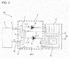
Fig. 2 is a circuit diagram schematically showing an example circuit configuration of arefrigeration cycle apparatus 100 according toEmbodiment 2 of the present invention. Therefrigeration cycle apparatus 100 will be described with reference toFig. 2 . Note that, inEmbodiment 2, an air-conditioning apparatus, serving as an example of therefrigeration cycle apparatus 100, will be described. Furthermore, inFig. 2 , flows of fluid, such as refrigerant and water, are shown by arrows. In the following description, the fluid, such as refrigerant and water, supplied from the heat source unit c to the distributor e will be referred to as fluid without distinction. - The
refrigeration cycle apparatus 100 includes, as one component, the distributor e according to the above-describedEmbodiment 1. More specifically, as shown inFig. 1 , therefrigeration cycle apparatus 100 includes one heat source unit c, a plurality of load-side units A (a load-side unit a and a load-side unit b), and the distributor e. AlthoughFig. 1 shows an example case where one heat source unit c is provided, the number of the heat source units c is not specifically limited, and a plurality of heat source units c may be provided in series or in parallel to be connected to the distributor e. Furthermore, althoughFig. 1 shows an example case where two load-side units A, namely, the load-side unit a and the load-side unit b, are connected, three or more load-side units may be connected in parallel to the distributor e. - The heat source unit c is used as, for example, an outdoor unit, depending on the purpose of the
refrigeration cycle apparatus 100, and supplies heat to the load-side units A via the fluid. This heat source unit c is the fluid supply side described inEmbodiment 1. - The heat source unit c accommodates a compressor, an expansion device, a heat-source-side heat exchanger, a fan, and other components, although they are not illustrated.
- When these components are connected by pipes to load-side heat exchangers accommodated in the load-side units A, these components and the load-side heat exchangers form a refrigerant circuit. In this case, the heat source is stored in the refrigerant, which is the fluid, and is supplied from the heat source unit c to the load-side units A.
- Alternatively, besides the heat-source-side heat exchanger, another heat exchanger may be provided in the heat source unit c to indirectly supply the heat source to the load-side units A. In this case, the heat source is stored in the water or other medium, which is the fluid, and is supplied to the load-side units A. In other words, the heat source stored in the refrigerant in the heat source unit c may be transmitted to another fluid, such as water, via another heat exchanger, and then this fluid may be supplied to the load-side units A.
- Note that, depending on the configuration of the heat-source-side heat exchanger, not the fan, but a pump that circulates water or antifreeze liquid is accommodated, as a heat-medium delivery device, in the heat source unit c.
- Depending on the purpose of the
refrigeration cycle apparatus 100, the load-side units A are used as, for example, indoor units or hot-water supply units, and heat or cool air, water or other load-side target, with the heat source supplied from the heat source unit c via the fluid. These load-side units A are the fluid distribution side described inEmbodiment 1. - The load-side units A accommodate the load-side heat exchangers, fans, and other components.
- Note that, depending on the configuration of the load-side heat exchangers, not the fans, but pumps that circulate water or antifreeze liquid are accommodated, as heat-medium delivery devices, in the load-side units A.
- Furthermore, the load-side heat exchanger accommodated in the load-side unit a will be referred to as a load-side heat exchanger a1, and the load-side heat exchanger accommodated in the load-side unit b will be referred to as a load-side heat exchanger b1.
- Moreover, when the load-side unit a and the load-side unit b do not have to be distinguished from one another, they will be referred to as the load-side units A in the description.
- The distributor e is connected between the heat source unit c and the load-side units A and distributes the fluid supplied from the heat source unit c among the load-side units A to be circulated.
- The configuration of the distributor e has been described in
Embodiment 1. - First, the operation of the
refrigeration cycle apparatus 100 when both the load-side unit a and the load-side unit b are used will be described. - In this case, the fluid supplied from the heat source unit c passes through the second
outgoing pipe 1 b and flows into the outgoing-side header 1 of the distributor e. The fluid flowing into the outgoing-side header 1 is separated into fluid flowing through the firstoutgoing pipe 1a-1 and fluid flowing through the firstoutgoing pipe 1 a-2. - The fluid flowing through the first
outgoing pipe 1a-1 flows into the load-side heat exchanger a1 of the load-side unit a, and, in the load-side heat exchanger a1, heats or cools the load-side target, such as air, water, and other heat medium, through heat exchange. - The fluid flowing through the first
outgoing pipe 1a-2 flows into the load-side heat exchanger b1 of the load-side unit b and, in the load-side heat exchanger b1, heats or cools the load-side target, such as air, water, and other heat medium, through heat exchange. - The fluids that have exchanged heat with the heat medium in the load-side heat exchanger a1 and the load-side heat exchanger b1 flow out from the load-side unit a and the load-side unit b.
- The fluid flowing out from the load-side unit a passes through the
first return pipe 2a-1 and flows into the return-side header 2 of the distributor e. - The fluid flowing out from the load-side unit b passes through the
first return pipe 2a-2 and flows into the return-side header 2 of the distributor e. - The fluids flowing into the return-
side header 2 are merged, pass through thesecond return pipe 2b, and return to the heat source unit c. - When the load-side unit a is used, the fluid returning from the load-side unit a flows through the
first return pipe 2a-1 into the return-side header 2. The fluid flowing into the return-side header 2 is guided to thesecond return pipe 2b, which is located immediately after thefirst return pipe 2a-1, that is, at the opposite side from thefirst return pipe 2a-1. Then, the fluid returns to the heat source unit c. Consequently, with the distributor e, because the fluid flowing into the return-side header 2 via thefirst return pipe 2a-1 returns to the heat source unit c via thesecond return pipe 2b, the fluid smoothly flows in the return-side header 2, and thus, the fluid is not short-cycled in the circuit of the load-side unit a. - Furthermore, also when the load-side unit b is used, the fluid returning from the load-side unit b flows through the
first return pipe 2a-2 into the return-side header 2. The fluid flowing into the return-side header 2 is guided to thesecond return pipe 2b, which is located at the opposite side from thefirst return pipe 2a-2. Then, the fluid returns to the heat source unit c. Consequently, with the distributor e, because the fluid flowing into the return-side header 2 via thefirst return pipe 2a-2 also returns to the heat source unit c via thesecond return pipe 2b, the fluid smoothly flows in the return-side header 2, and thus, the fluid is not short-cycled in the circuit of the load-side unit a. - When both the load-side unit a and the load-side unit b are used, the fluids returning from the load-side unit a and the load-side unit b flow, respectively, through the
first return pipe 2a-1 and thefirst return pipe 2a-2 into the return-side header 2. The fluids flowing into the return-side header 2 are merged and guided to thesecond return pipe 2b, which is located at the opposite side from thefirst return pipe 2a-1 and thefirst return pipe 2a-2. Then, the fluid returns to the heat source unit c. Consequently, with the distributor e, because the fluid merged in the return-side header 2 smoothly returns to the heat source unit c via thesecond return pipe 2b, the fluid is not blocked in the return-side header 2, and thus, the fluid is not short-cycled in the circuit of the load-side unit a. - Next, the operation of the
refrigeration cycle apparatus 100 when only one of the load-side unit a and the load-side unit b is used will be described. Here, an example case where the load-side unit a is used and the load-side unit b is not used will be described. - In this case, the fluid supplied from the heat source unit c passes through the second
outgoing pipe 1 b and flows into the outgoing-side header 1 of the distributor e. The fluid flowing into the outgoing-side header 1 is guided to the firstoutgoing pipe 1a-1. More specifically, in this case, only thepump 5a is driven, and thepump 5b is stopped. Hence, the fluid flowing into the outgoing-side header 1 is guided only to the firstoutgoing pipe 1a-1. - The fluid flowing through the first
outgoing pipe 1a-1 flows into the load-side heat exchanger a1 of the load-side unit a, and, in the load-side heat exchanger a1, heats or cools the load-side target, such as air, water, and other heat medium, through heat exchange. - The fluid that has exchanged heat with the heat medium in the load-side heat exchanger a1 flows out from the load-side unit a.
- The fluid flowing out from the load-side unit a passes through the
first return pipe 2a-1 and flows into the return-side header 2 of the distributor e. - The fluid flowing into the return-
side header 2 returns to the heat source unit c through thesecond return pipe 2b. - When only one of the load-side unit a and the load-side unit b is used, because the connecting position of the
second return pipe 2b is closer to the outgoing-side header 1 than are the connecting positions of thefirst return pipe 2a-1 and thefirst return pipe 2a-2, as viewed from the heat source unit c side, it is possible to prevent backflow of fluid to the load-side unit that is not used. - Now, a case is assumed that a certain load-side unit is frequently used and opening and closing of a circuit are frequently repeated. Herein, an example case where the load-side unit b is such a frequently used load-side unit, in which opening and closing of the circuit are frequently repeated will be described. Note that the frequencies of use of the load-side units A are set when the
refrigeration cycle apparatus 100 is installed. Furthermore, what is meant by "frequently used" is that it is preliminarily assumed that the frequency of use will be high, depending on the purpose of the load-side unit connected. The purposes of the load-side units include air conditioning for habitable rooms, air conditioning for warehouses, air conditioning for shared spaces, floor heating, and hot-water supply. - The
first return pipe 2a-2 connecting the load-side unit b and the return-side header 2 is connected to the return-side header 2, at a position farthest from thesecond return pipe 2b among all of the return pipes connected to the load-side units A. With this configuration, even in the case where the load-side unit b is frequently used, and opening and closing of the circuit are frequently repeated, a fluid flow is not inhibited in the return-side header 2, and thus, the fluid is not short-cycled in the load-side unit b, and backflow of fluid from the heat source unit c side does not occur. - As described above, because the
refrigeration cycle apparatus 100 includes the distributor e as a component, it is possible to prevent the occurrence of short cycling in load-side-unit-side circuits, with a simple pipe configuration that does not require a part such as a check valve. - Furthermore, because the
refrigeration cycle apparatus 100 is configured such that the inside diameter of thebypass pipe 3 is smaller than the inside diameter of each of the outgoing-side header 1 and the return-side header 2, it is possible to prevent short cycling of fluid from occurring in the load-side-unit-side circuits. - Moreover, in the
refrigeration cycle apparatus 100, because thesecond return pipe 2b is connected at a position closest to the heat source unit c side among all of the return pipes, even during an operation in which not all the load-side units are used, backflow of fluid to the load-side-unit-side circuits does not occur. Reference Signs List - 1 outgoing-
side header 1a-1 firstoutgoing pipe 1 a-2 firstoutgoing pipe 1b secondoutgoing pipe 2 return-side header 2a-1first return pipe 2a-2first return pipe 2bsecond return pipe 3bypass 100 refrigeration cycle apparatus A load-side unit a load-side unit a1 load-side heat exchanger b load-side unit b1 load-side heat exchanger c heat source unit e distributorpipe 5apump 5b pump
Claims (8)
- A distributor comprising:an outgoing-side header to which a plurality of outgoing pipes are connected; anda return-side header to which a plurality of return pipes are connected,the plurality of outgoing pipes including at least two first outgoing pipes connected to a fluid distribution side and a second outgoing pipe connected to a fluid supply side,the plurality of return pipes including at least two first return pipes connected to the fluid distribution side and a second return pipe connected to the fluid supply side,the second return pipe being connected to the return-side header, on a downstream side in a direction in which fluid returning from the at least two first return pipes flows, and at an opposite side, across a longitudinal direction of the return-side header, from connecting positions of the at least two first return pipes to the return-side header.
- The distributor of claim 1, wherein
the outgoing-side header and the return-side header are disposed to be parallel to each other in the longitudinal direction, and
the second return pipe is connected at a position closer to the outgoing-side header than are the connecting positions of the at least two first return pipes to the return-side header. - The distributor of claim 1 or 2, wherein the second outgoing pipe is connected to the outgoing-side header between connecting positions of the at least two first outgoing pipes in the longitudinal direction of the outgoing-side header.
- The distributor of claim 3, wherein the at least two first outgoing pipes are connected in parallel to each other to the outgoing-side header, at an opposite side from a connecting position of the second outgoing pipe to the outgoing-side header.
- The distributor of any one of claims 1 to 4, wherein the at least two first return pipes are connected in parallel to each other to the return-side header, at an opposite side from a connecting position of the second return pipe to the return-side header.
- The distributor of any one of claims 1 to 5, further comprising a bypass pipe connecting the outgoing-side header and the return-side header, wherein an inside diameter of the bypass pipe is smaller than an inside diameter of each of the at least two first outgoing pipes, the second outgoing pipe, the at least two first return pipes, and the second return pipe.
- A refrigeration cycle apparatus comprising:a heat source unit;a plurality of load-side units; andthe distributor of any one of claims 1 to 6 that is connected between the heat source unit and the plurality of load-side units.
- The refrigeration cycle apparatus of claim 7, wherein one of the at least two first return pipes connected to one of the plurality of load-side units that is preset to be frequently used is connected to the return-side header at a position farthest from the second return pipe among all of the at least two first return pipes.
Applications Claiming Priority (1)
| Application Number | Priority Date | Filing Date | Title |
|---|---|---|---|
| PCT/JP2016/071766 WO2018020557A1 (en) | 2016-07-25 | 2016-07-25 | Distributor and refrigeration cycle apparatus |
Publications (3)
| Publication Number | Publication Date |
|---|---|
| EP3309476A1 true EP3309476A1 (en) | 2018-04-18 |
| EP3309476A4 EP3309476A4 (en) | 2018-06-13 |
| EP3309476B1 EP3309476B1 (en) | 2019-08-28 |
Family
ID=61016937
Family Applications (1)
| Application Number | Title | Priority Date | Filing Date |
|---|---|---|---|
| EP16904240.5A Active EP3309476B1 (en) | 2016-07-25 | 2016-07-25 | Distributor and refrigeration cycle apparatus |
Country Status (4)
| Country | Link |
|---|---|
| EP (1) | EP3309476B1 (en) |
| JP (1) | JP6599010B2 (en) |
| CN (1) | CN207797467U (en) |
| WO (1) | WO2018020557A1 (en) |
Families Citing this family (1)
| Publication number | Priority date | Publication date | Assignee | Title |
|---|---|---|---|---|
| KR102185948B1 (en) * | 2019-05-29 | 2020-12-03 | 한국에너지기술연구원 | Bi-directional thermal energy control system |
Family Cites Families (10)
| Publication number | Priority date | Publication date | Assignee | Title |
|---|---|---|---|---|
| JPS581711Y2 (en) * | 1978-07-06 | 1983-01-12 | 三菱電機株式会社 | Header device for cooling or heating |
| JPS5716708U (en) | 1980-07-04 | 1982-01-28 | ||
| JPH03274327A (en) * | 1990-03-22 | 1991-12-05 | Matsushita Electric Ind Co Ltd | Hot water space heating device |
| US6092734A (en) * | 1995-08-29 | 2000-07-25 | Monard (Research & Development) Limited | Manifold for connecting circuits of a central heating system |
| JP2002250526A (en) * | 2001-02-23 | 2002-09-06 | Corona Corp | Device for detecting pressure abnormality of warm water system |
| JP2005069368A (en) * | 2003-08-25 | 2005-03-17 | Rinnai Corp | Warm water piping structure |
| JP4249591B2 (en) * | 2003-10-23 | 2009-04-02 | 株式会社山武 | Primary pump type heat source variable flow rate control system and primary pump minimum flow rate securing method |
| NL1025535C2 (en) * | 2004-02-20 | 2004-12-28 | J K Beheer B V | Distributor for underfloor heating system, has cross flow restricting device in opening in compartment wall |
| EP2014992A1 (en) * | 2007-07-13 | 2009-01-14 | Helmut Burtscher | Tempering facility distributor |
| WO2016075676A1 (en) * | 2014-11-12 | 2016-05-19 | Rea David Patrick | A manifold, a buffer tank comprising the manifold, and a method for operating a heat exchange system |
-
2016
- 2016-07-25 WO PCT/JP2016/071766 patent/WO2018020557A1/en unknown
- 2016-07-25 EP EP16904240.5A patent/EP3309476B1/en active Active
- 2016-07-25 CN CN201690000890.9U patent/CN207797467U/en active Active
- 2016-07-25 JP JP2018530218A patent/JP6599010B2/en active Active
Also Published As
| Publication number | Publication date |
|---|---|
| WO2018020557A1 (en) | 2018-02-01 |
| JPWO2018020557A1 (en) | 2019-03-14 |
| JP6599010B2 (en) | 2019-10-30 |
| EP3309476B1 (en) | 2019-08-28 |
| EP3309476A4 (en) | 2018-06-13 |
| CN207797467U (en) | 2018-08-31 |
Similar Documents
| Publication | Publication Date | Title |
|---|---|---|
| AU2005258416B2 (en) | Hot water supply system | |
| US9593872B2 (en) | Heat pump | |
| EP2833072B1 (en) | Heating and hot water supply system | |
| EP3325898B1 (en) | Hydronic system for combining free cooling and mechanical cooling | |
| CN104813757A (en) | Heat exchanger for cooling a switch cabinet and corresponding cooling arrangement | |
| EP3217135A1 (en) | Layered header, heat exchanger, and air-conditioning device | |
| EP3306215B1 (en) | Air-conditioning device | |
| US11448429B2 (en) | Air and water cooled chiller for free cooling applications | |
| EP2597400A2 (en) | Heat pump system | |
| US11578898B2 (en) | Air conditioning apparatus | |
| EP3401609B1 (en) | Air-conditioning device | |
| US11499727B2 (en) | Air conditioning apparatus | |
| EP3309476B1 (en) | Distributor and refrigeration cycle apparatus | |
| CA3028624C (en) | Central air conditioning and heat pump system with energy efficient arrangement | |
| CN208653007U (en) | Refrigeration equipment | |
| CN104344595B (en) | Air conditioning system | |
| JP6118065B2 (en) | Water-cooled air conditioning system and operation control method thereof | |
| US11359842B2 (en) | Air conditioning apparatus | |
| CN209416099U (en) | Cooling equipment | |
| CN109405583B (en) | Cooling apparatus | |
| CN112050305A (en) | Multi-zone air conditioning system and operation method thereof | |
| KR101171915B1 (en) | an air conditioning system with all in one | |
| KR101283252B1 (en) | Thermal media equal distribution type air conditioning unit | |
| CN104949195A (en) | Multi-connected air conditioning unit | |
| US20200326092A1 (en) | Air conditioning apparatus |
Legal Events
| Date | Code | Title | Description |
|---|---|---|---|
| STAA | Information on the status of an ep patent application or granted ep patent |
Free format text: STATUS: UNKNOWN |
|
| STAA | Information on the status of an ep patent application or granted ep patent |
Free format text: STATUS: THE INTERNATIONAL PUBLICATION HAS BEEN MADE |
|
| PUAI | Public reference made under article 153(3) epc to a published international application that has entered the european phase |
Free format text: ORIGINAL CODE: 0009012 |
|
| STAA | Information on the status of an ep patent application or granted ep patent |
Free format text: STATUS: REQUEST FOR EXAMINATION WAS MADE |
|
| 17P | Request for examination filed |
Effective date: 20171211 |
|
| AK | Designated contracting states |
Kind code of ref document: A1 Designated state(s): AL AT BE BG CH CY CZ DE DK EE ES FI FR GB GR HR HU IE IS IT LI LT LU LV MC MK MT NL NO PL PT RO RS SE SI SK SM TR |
|
| AX | Request for extension of the european patent |
Extension state: BA ME |
|
| A4 | Supplementary search report drawn up and despatched |
Effective date: 20180515 |
|
| RIC1 | Information provided on ipc code assigned before grant |
Ipc: F15D 1/02 20060101ALI20180508BHEP Ipc: F24D 3/10 20060101ALI20180508BHEP Ipc: F25B 41/00 20060101AFI20180508BHEP Ipc: F24D 3/18 20060101ALI20180508BHEP |
|
| GRAP | Despatch of communication of intention to grant a patent |
Free format text: ORIGINAL CODE: EPIDOSNIGR1 |
|
| STAA | Information on the status of an ep patent application or granted ep patent |
Free format text: STATUS: GRANT OF PATENT IS INTENDED |
|
| RIC1 | Information provided on ipc code assigned before grant |
Ipc: F24D 3/18 20060101ALI20190206BHEP Ipc: F24D 3/10 20060101ALI20190206BHEP Ipc: F15D 1/02 20060101ALI20190206BHEP Ipc: F25B 41/00 20060101AFI20190206BHEP |
|
| DAX | Request for extension of the european patent (deleted) | ||
| INTG | Intention to grant announced |
Effective date: 20190304 |
|
| RIN1 | Information on inventor provided before grant (corrected) |
Inventor name: KAWAMURA, TAKESHI Inventor name: HASEGAWA, YUKI |
|
| GRAS | Grant fee paid |
Free format text: ORIGINAL CODE: EPIDOSNIGR3 |
|
| GRAA | (expected) grant |
Free format text: ORIGINAL CODE: 0009210 |
|
| STAA | Information on the status of an ep patent application or granted ep patent |
Free format text: STATUS: THE PATENT HAS BEEN GRANTED |
|
| DAV | Request for validation of the european patent (deleted) | ||
| AK | Designated contracting states |
Kind code of ref document: B1 Designated state(s): AL AT BE BG CH CY CZ DE DK EE ES FI FR GB GR HR HU IE IS IT LI LT LU LV MC MK MT NL NO PL PT RO RS SE SI SK SM TR |
|
| REG | Reference to a national code |
Ref country code: GB Ref legal event code: FG4D |
|
| REG | Reference to a national code |
Ref country code: CH Ref legal event code: EP |
|
| REG | Reference to a national code |
Ref country code: DE Ref legal event code: R096 Ref document number: 602016019686 Country of ref document: DE |
|
| REG | Reference to a national code |
Ref country code: AT Ref legal event code: REF Ref document number: 1172911 Country of ref document: AT Kind code of ref document: T Effective date: 20190915 |
|
| REG | Reference to a national code |
Ref country code: IE Ref legal event code: FG4D |
|
| REG | Reference to a national code |
Ref country code: NL Ref legal event code: MP Effective date: 20190828 |
|
| REG | Reference to a national code |
Ref country code: LT Ref legal event code: MG4D |
|
| PG25 | Lapsed in a contracting state [announced via postgrant information from national office to epo] |
Ref country code: SE Free format text: LAPSE BECAUSE OF FAILURE TO SUBMIT A TRANSLATION OF THE DESCRIPTION OR TO PAY THE FEE WITHIN THE PRESCRIBED TIME-LIMIT Effective date: 20190828 Ref country code: HR Free format text: LAPSE BECAUSE OF FAILURE TO SUBMIT A TRANSLATION OF THE DESCRIPTION OR TO PAY THE FEE WITHIN THE PRESCRIBED TIME-LIMIT Effective date: 20190828 Ref country code: LT Free format text: LAPSE BECAUSE OF FAILURE TO SUBMIT A TRANSLATION OF THE DESCRIPTION OR TO PAY THE FEE WITHIN THE PRESCRIBED TIME-LIMIT Effective date: 20190828 Ref country code: PT Free format text: LAPSE BECAUSE OF FAILURE TO SUBMIT A TRANSLATION OF THE DESCRIPTION OR TO PAY THE FEE WITHIN THE PRESCRIBED TIME-LIMIT Effective date: 20191230 Ref country code: NL Free format text: LAPSE BECAUSE OF FAILURE TO SUBMIT A TRANSLATION OF THE DESCRIPTION OR TO PAY THE FEE WITHIN THE PRESCRIBED TIME-LIMIT Effective date: 20190828 Ref country code: BG Free format text: LAPSE BECAUSE OF FAILURE TO SUBMIT A TRANSLATION OF THE DESCRIPTION OR TO PAY THE FEE WITHIN THE PRESCRIBED TIME-LIMIT Effective date: 20191128 Ref country code: FI Free format text: LAPSE BECAUSE OF FAILURE TO SUBMIT A TRANSLATION OF THE DESCRIPTION OR TO PAY THE FEE WITHIN THE PRESCRIBED TIME-LIMIT Effective date: 20190828 Ref country code: NO Free format text: LAPSE BECAUSE OF FAILURE TO SUBMIT A TRANSLATION OF THE DESCRIPTION OR TO PAY THE FEE WITHIN THE PRESCRIBED TIME-LIMIT Effective date: 20191128 |
|
| PG25 | Lapsed in a contracting state [announced via postgrant information from national office to epo] |
Ref country code: ES Free format text: LAPSE BECAUSE OF FAILURE TO SUBMIT A TRANSLATION OF THE DESCRIPTION OR TO PAY THE FEE WITHIN THE PRESCRIBED TIME-LIMIT Effective date: 20190828 Ref country code: RS Free format text: LAPSE BECAUSE OF FAILURE TO SUBMIT A TRANSLATION OF THE DESCRIPTION OR TO PAY THE FEE WITHIN THE PRESCRIBED TIME-LIMIT Effective date: 20190828 Ref country code: IS Free format text: LAPSE BECAUSE OF FAILURE TO SUBMIT A TRANSLATION OF THE DESCRIPTION OR TO PAY THE FEE WITHIN THE PRESCRIBED TIME-LIMIT Effective date: 20191228 Ref country code: LV Free format text: LAPSE BECAUSE OF FAILURE TO SUBMIT A TRANSLATION OF THE DESCRIPTION OR TO PAY THE FEE WITHIN THE PRESCRIBED TIME-LIMIT Effective date: 20190828 Ref country code: AL Free format text: LAPSE BECAUSE OF FAILURE TO SUBMIT A TRANSLATION OF THE DESCRIPTION OR TO PAY THE FEE WITHIN THE PRESCRIBED TIME-LIMIT Effective date: 20190828 Ref country code: GR Free format text: LAPSE BECAUSE OF FAILURE TO SUBMIT A TRANSLATION OF THE DESCRIPTION OR TO PAY THE FEE WITHIN THE PRESCRIBED TIME-LIMIT Effective date: 20191129 |
|
| REG | Reference to a national code |
Ref country code: AT Ref legal event code: MK05 Ref document number: 1172911 Country of ref document: AT Kind code of ref document: T Effective date: 20190828 |
|
| PG25 | Lapsed in a contracting state [announced via postgrant information from national office to epo] |
Ref country code: TR Free format text: LAPSE BECAUSE OF FAILURE TO SUBMIT A TRANSLATION OF THE DESCRIPTION OR TO PAY THE FEE WITHIN THE PRESCRIBED TIME-LIMIT Effective date: 20190828 |
|
| PG25 | Lapsed in a contracting state [announced via postgrant information from national office to epo] |
Ref country code: IT Free format text: LAPSE BECAUSE OF FAILURE TO SUBMIT A TRANSLATION OF THE DESCRIPTION OR TO PAY THE FEE WITHIN THE PRESCRIBED TIME-LIMIT Effective date: 20190828 Ref country code: RO Free format text: LAPSE BECAUSE OF FAILURE TO SUBMIT A TRANSLATION OF THE DESCRIPTION OR TO PAY THE FEE WITHIN THE PRESCRIBED TIME-LIMIT Effective date: 20190828 Ref country code: AT Free format text: LAPSE BECAUSE OF FAILURE TO SUBMIT A TRANSLATION OF THE DESCRIPTION OR TO PAY THE FEE WITHIN THE PRESCRIBED TIME-LIMIT Effective date: 20190828 Ref country code: DK Free format text: LAPSE BECAUSE OF FAILURE TO SUBMIT A TRANSLATION OF THE DESCRIPTION OR TO PAY THE FEE WITHIN THE PRESCRIBED TIME-LIMIT Effective date: 20190828 Ref country code: EE Free format text: LAPSE BECAUSE OF FAILURE TO SUBMIT A TRANSLATION OF THE DESCRIPTION OR TO PAY THE FEE WITHIN THE PRESCRIBED TIME-LIMIT Effective date: 20190828 Ref country code: PL Free format text: LAPSE BECAUSE OF FAILURE TO SUBMIT A TRANSLATION OF THE DESCRIPTION OR TO PAY THE FEE WITHIN THE PRESCRIBED TIME-LIMIT Effective date: 20190828 |
|
| PG25 | Lapsed in a contracting state [announced via postgrant information from national office to epo] |
Ref country code: CZ Free format text: LAPSE BECAUSE OF FAILURE TO SUBMIT A TRANSLATION OF THE DESCRIPTION OR TO PAY THE FEE WITHIN THE PRESCRIBED TIME-LIMIT Effective date: 20190828 Ref country code: SK Free format text: LAPSE BECAUSE OF FAILURE TO SUBMIT A TRANSLATION OF THE DESCRIPTION OR TO PAY THE FEE WITHIN THE PRESCRIBED TIME-LIMIT Effective date: 20190828 Ref country code: IS Free format text: LAPSE BECAUSE OF FAILURE TO SUBMIT A TRANSLATION OF THE DESCRIPTION OR TO PAY THE FEE WITHIN THE PRESCRIBED TIME-LIMIT Effective date: 20200224 Ref country code: SM Free format text: LAPSE BECAUSE OF FAILURE TO SUBMIT A TRANSLATION OF THE DESCRIPTION OR TO PAY THE FEE WITHIN THE PRESCRIBED TIME-LIMIT Effective date: 20190828 |
|
| REG | Reference to a national code |
Ref country code: DE Ref legal event code: R097 Ref document number: 602016019686 Country of ref document: DE |
|
| PLBE | No opposition filed within time limit |
Free format text: ORIGINAL CODE: 0009261 |
|
| STAA | Information on the status of an ep patent application or granted ep patent |
Free format text: STATUS: NO OPPOSITION FILED WITHIN TIME LIMIT |
|
| PG2D | Information on lapse in contracting state deleted |
Ref country code: IS |
|
| 26N | No opposition filed |
Effective date: 20200603 |
|
| PG25 | Lapsed in a contracting state [announced via postgrant information from national office to epo] |
Ref country code: SI Free format text: LAPSE BECAUSE OF FAILURE TO SUBMIT A TRANSLATION OF THE DESCRIPTION OR TO PAY THE FEE WITHIN THE PRESCRIBED TIME-LIMIT Effective date: 20190828 |
|
| PG25 | Lapsed in a contracting state [announced via postgrant information from national office to epo] |
Ref country code: MC Free format text: LAPSE BECAUSE OF FAILURE TO SUBMIT A TRANSLATION OF THE DESCRIPTION OR TO PAY THE FEE WITHIN THE PRESCRIBED TIME-LIMIT Effective date: 20190828 |
|
| REG | Reference to a national code |
Ref country code: CH Ref legal event code: PL |
|
| REG | Reference to a national code |
Ref country code: BE Ref legal event code: MM Effective date: 20200731 |
|
| PG25 | Lapsed in a contracting state [announced via postgrant information from national office to epo] |
Ref country code: FR Free format text: LAPSE BECAUSE OF NON-PAYMENT OF DUE FEES Effective date: 20200731 Ref country code: CH Free format text: LAPSE BECAUSE OF NON-PAYMENT OF DUE FEES Effective date: 20200731 Ref country code: LU Free format text: LAPSE BECAUSE OF NON-PAYMENT OF DUE FEES Effective date: 20200725 Ref country code: LI Free format text: LAPSE BECAUSE OF NON-PAYMENT OF DUE FEES Effective date: 20200731 |
|
| PG25 | Lapsed in a contracting state [announced via postgrant information from national office to epo] |
Ref country code: BE Free format text: LAPSE BECAUSE OF NON-PAYMENT OF DUE FEES Effective date: 20200731 |
|
| PG25 | Lapsed in a contracting state [announced via postgrant information from national office to epo] |
Ref country code: IE Free format text: LAPSE BECAUSE OF NON-PAYMENT OF DUE FEES Effective date: 20200725 |
|
| PG25 | Lapsed in a contracting state [announced via postgrant information from national office to epo] |
Ref country code: MT Free format text: LAPSE BECAUSE OF FAILURE TO SUBMIT A TRANSLATION OF THE DESCRIPTION OR TO PAY THE FEE WITHIN THE PRESCRIBED TIME-LIMIT Effective date: 20190828 Ref country code: CY Free format text: LAPSE BECAUSE OF FAILURE TO SUBMIT A TRANSLATION OF THE DESCRIPTION OR TO PAY THE FEE WITHIN THE PRESCRIBED TIME-LIMIT Effective date: 20190828 |
|
| PG25 | Lapsed in a contracting state [announced via postgrant information from national office to epo] |
Ref country code: MK Free format text: LAPSE BECAUSE OF FAILURE TO SUBMIT A TRANSLATION OF THE DESCRIPTION OR TO PAY THE FEE WITHIN THE PRESCRIBED TIME-LIMIT Effective date: 20190828 |
|
| P01 | Opt-out of the competence of the unified patent court (upc) registered |
Effective date: 20230512 |
|
| PGFP | Annual fee paid to national office [announced via postgrant information from national office to epo] |
Ref country code: GB Payment date: 20230601 Year of fee payment: 8 |
|
| PGFP | Annual fee paid to national office [announced via postgrant information from national office to epo] |
Ref country code: DE Payment date: 20230531 Year of fee payment: 8 |