WO2018020557A1 - Distributeur et appareil à cycle frigorifique - Google Patents
Distributeur et appareil à cycle frigorifique Download PDFInfo
- Publication number
- WO2018020557A1 WO2018020557A1 PCT/JP2016/071766 JP2016071766W WO2018020557A1 WO 2018020557 A1 WO2018020557 A1 WO 2018020557A1 JP 2016071766 W JP2016071766 W JP 2016071766W WO 2018020557 A1 WO2018020557 A1 WO 2018020557A1
- Authority
- WO
- WIPO (PCT)
- Prior art keywords
- return
- header
- pipe
- fluid
- distributor
- Prior art date
Links
- 238000005057 refrigeration Methods 0.000 title claims description 26
- 239000012530 fluid Substances 0.000 claims abstract description 107
- XLYOFNOQVPJJNP-UHFFFAOYSA-N water Substances O XLYOFNOQVPJJNP-UHFFFAOYSA-N 0.000 description 32
- 239000003507 refrigerant Substances 0.000 description 5
- 238000010438 heat treatment Methods 0.000 description 4
- 238000004378 air conditioning Methods 0.000 description 3
- 230000002528 anti-freeze Effects 0.000 description 2
- 238000010586 diagram Methods 0.000 description 2
- 239000000470 constituent Substances 0.000 description 1
- 238000009434 installation Methods 0.000 description 1
- 239000007788 liquid Substances 0.000 description 1
Images

Classifications
-
- F—MECHANICAL ENGINEERING; LIGHTING; HEATING; WEAPONS; BLASTING
- F24—HEATING; RANGES; VENTILATING
- F24D—DOMESTIC- OR SPACE-HEATING SYSTEMS, e.g. CENTRAL HEATING SYSTEMS; DOMESTIC HOT-WATER SUPPLY SYSTEMS; ELEMENTS OR COMPONENTS THEREFOR
- F24D3/00—Hot-water central heating systems
- F24D3/18—Hot-water central heating systems using heat pumps
-
- F—MECHANICAL ENGINEERING; LIGHTING; HEATING; WEAPONS; BLASTING
- F24—HEATING; RANGES; VENTILATING
- F24D—DOMESTIC- OR SPACE-HEATING SYSTEMS, e.g. CENTRAL HEATING SYSTEMS; DOMESTIC HOT-WATER SUPPLY SYSTEMS; ELEMENTS OR COMPONENTS THEREFOR
- F24D3/00—Hot-water central heating systems
- F24D3/10—Feed-line arrangements, e.g. providing for heat-accumulator tanks, expansion tanks ; Hydraulic components of a central heating system
- F24D3/1058—Feed-line arrangements, e.g. providing for heat-accumulator tanks, expansion tanks ; Hydraulic components of a central heating system disposition of pipes and pipe connections
- F24D3/1066—Distributors for heating liquids
-
- F—MECHANICAL ENGINEERING; LIGHTING; HEATING; WEAPONS; BLASTING
- F25—REFRIGERATION OR COOLING; COMBINED HEATING AND REFRIGERATION SYSTEMS; HEAT PUMP SYSTEMS; MANUFACTURE OR STORAGE OF ICE; LIQUEFACTION SOLIDIFICATION OF GASES
- F25B—REFRIGERATION MACHINES, PLANTS OR SYSTEMS; COMBINED HEATING AND REFRIGERATION SYSTEMS; HEAT PUMP SYSTEMS
- F25B41/00—Fluid-circulation arrangements
-
- Y—GENERAL TAGGING OF NEW TECHNOLOGICAL DEVELOPMENTS; GENERAL TAGGING OF CROSS-SECTIONAL TECHNOLOGIES SPANNING OVER SEVERAL SECTIONS OF THE IPC; TECHNICAL SUBJECTS COVERED BY FORMER USPC CROSS-REFERENCE ART COLLECTIONS [XRACs] AND DIGESTS
- Y02—TECHNOLOGIES OR APPLICATIONS FOR MITIGATION OR ADAPTATION AGAINST CLIMATE CHANGE
- Y02B—CLIMATE CHANGE MITIGATION TECHNOLOGIES RELATED TO BUILDINGS, e.g. HOUSING, HOUSE APPLIANCES OR RELATED END-USER APPLICATIONS
- Y02B30/00—Energy efficient heating, ventilation or air conditioning [HVAC]
- Y02B30/12—Hot water central heating systems using heat pumps
Definitions
- the present invention relates to a distributor that distributes a fluid to a plurality of units, and a refrigeration cycle apparatus including the distributor.
- Such a refrigeration cycle apparatus is used as an air conditioner or a water heater.
- a plurality of indoor units are connected to one outdoor unit, and a distributor (header) for distributing and circulating a fluid from the outdoor unit side to the indoor unit side is provided.
- a hot water heating header as described in Patent Document 1 has been proposed.
- the header for hot water heating described in Patent Document 1 includes a hot water supply pipe header to which a hot water supply pipe (outward piping) for supplying hot water to a load equipment (indoor unit) is connected, and hot water used in the load equipment. And a hot water return header to which a hot water return pipe (return pipe) returning to the heat source machine (hot water storage tank) is connected.
- a hot water supply pipe header to which a hot water supply pipe (outward piping) for supplying hot water to a load equipment (indoor unit) is connected, and hot water used in the load equipment.
- a hot water return header to which a hot water return pipe (return pipe) returning to the heat source machine (hot water storage tank) is connected.
- the warm water heating header described in Patent Document 1 has a double-pipe structure of a warm water supply header and a warm water return header, and has a circuit configuration that bypasses each other by forming a bypass hole in the warm water supply header. ing.
- Patent Document 1 when the inner diameter of the bypass hole is equal to or larger than the diameter of the outlet, the fluid may short cycle even on the heat source side.
- Patent Document 1 since the warm water supply header and the warm water return header have a double pipe structure, the fluid flowing through the warm water supply header and the fluid flowing through the warm water return header exchange heat. As a result, the heat exchange efficiency is also reduced.
- the present invention has been made against the background of the above problems, and an object of the present invention is to provide a distributor in which a short cycle of fluid does not occur, and a refrigeration cycle apparatus including the distributor. .
- the distributor according to the present invention has a forward header to which a plurality of forward pipes are connected, and a return header to which a plurality of return pipes are connected. Including at least two first forward pipes connected to the fluid distribution side and one second forward pipe connected to the fluid supply side, wherein the plurality of return pipes are connected to the fluid distribution side. At least two first return pipes connected to the fluid supply side, and one second return pipe connected to the fluid supply side, wherein the second return pipe includes at least two of the first return pipes.
- the downstream side of the flow direction of the fluid returning from the return pipe, and the connection position of the return side header of at least two of the first return pipes is connected to the opposite side in the longitudinal direction of the return side header Is.
- a refrigeration cycle apparatus includes a heat source unit, a plurality of load side units, and the distributor connected between the heat source unit and the plurality of load side units. .
- the second return pipe is downstream in the flow direction of the fluid returning from the at least two first return pipes, and the return header of the at least two first return pipes Since the connection position is connected to the opposite side of the longitudinal direction of the return header, the flow of fluid is not hindered in the return header, and a short cycle of fluid does not occur in the circuit on the fluid distribution side.
- the refrigeration cycle apparatus uses the distributor described above, there is no occurrence of a fluid short cycle in the circuit on the fluid distribution side, and there is no reduction in efficiency due to the fluid short cycle. .
- FIG. 1 is a perspective view showing a configuration example of a distributor e according to Embodiment 1 of the present invention.
- the distributor e will be described with reference to FIG.
- the distributor e is connected between at least one outdoor unit constituting a refrigeration cycle apparatus such as an air conditioner and a plurality of indoor units, and distributes the fluid to each of the plurality of indoor units. It is.
- the outdoor unit side that is a heat source unit is referred to as a fluid supply side
- the indoor unit side that is a load device is referred to as a fluid distribution side.
- the distributor e has a forward header 1 for distributing the fluid and a return header 2 for joining the fluid.
- the forward header 1 and the return header 2 are arranged so that, for example, the fluid flow direction, that is, the longitudinal direction is parallel.
- the forward header 1 and the return header 2 are connected by a bypass pipe 3.
- the bypass pipe 3 connects one end side of the outgoing header 1 and one end side of the return header 2. That is, the bypass pipe 3 connects the forward header 1 and the return header 2 on the side surface on the right end side of the drawing.
- the bypass pipe 3 extends linearly and connects the facing positions of the forward header 1 and the return header 2.
- the bypass pipe 3 is configured so that the inner diameter is smaller than both the forward pipe connected to the forward header 1 and the inner diameter of the return pipe connected to the return header 2. By doing so, the flow of fluid in the bypass pipe 3 can be made harder than the flow of fluid in the forward pipe. By doing so, it is possible to reduce the short cycle of the fluid on the fluid supply side and the reverse flow of the fluid on the fluid distribution side.
- a plurality of outgoing pipes are connected to the outgoing header 1.
- at least two forward pipes connected to the fluid distribution side are referred to as a first forward pipe 1a-1 and a first forward pipe 1a-2.
- at least one forward pipe connected to the fluid supply side is referred to as a second forward pipe 1b.
- the first forward pipe 1 a-1 and the first forward pipe 1 a-2 are arranged in parallel with the forward header 1.
- the second forward pipe 1b is on the side facing the first forward pipe 1a-1 and the first forward pipe 1a-2, and the connection position of the first forward pipe 1a-1 and the first forward pipe 1a-2. It is connected between the connection position.
- connection position of the second forward pipe 1b is the first forward pipe 1a-1 and the side where the second forward pipe 1b faces the first forward pipe 1a-1 and the first forward pipe 1a-2. It means that it is located on the opposite side to the connection position of the first forward pipe 1a-2.
- a pump 5a for circulating a fluid is installed in the first forward pipe 1a-1.
- a pump 5b for circulating a fluid is installed in the first forward pipe 1a-2.
- a plurality of return pipes are connected to the return side header 2.
- at least two return pipes connected to the fluid distribution side are referred to as a first return pipe 2a-1 and a first return pipe 2a-2.
- at least one return pipe connected to the fluid supply side is referred to as a second return pipe 2b.
- the first return pipe 2 a-1 and the first return pipe 2 a-2 are arranged in parallel to the return side header 2.
- the second return pipe 2b is connected to a position facing the first return pipe 2a-1 and the first return pipe 2a-2 on the side facing the first return pipe 2a-1 and the first return pipe 2a-2.
- connection position of the second return pipe 2b and the side where the second return pipe 2b faces the first return pipe 2a-1 and the first return pipe 2a-2 are the first return pipe 2a-1 and the first return pipe 2a-1. It means that it is located on the opposite side to the connection position of the first return pipe 2a-2.
- the pump 5a may be installed in the first return pipe 2a-1 instead of the first forward pipe 1a-1
- the pump 5b is installed in the first return pipe 2a-2 instead of the first forward pipe 1a-2. May be installed.
- the distributor e branches the fluid into two is shown as an example, but the number of branches of the fluid is not particularly limited.
- the second return pipe 2b is positioned closest to the forward header 1 relative to the connection position of the other return pipe, that is, the fluid returning from the first return pipe. What is necessary is just to connect with the connection position of the return side header 2 of the 1st return piping to the other side of the longitudinal direction of the return side header 2 downstream in the flow direction. By doing so, the flow of fluid in the return header 2 is not hindered.
- connection position of the return pipe (second return pipe 2b) connected to the fluid supply side at the return header 2 is the return pipe (first pipe connected to the fluid distribution side).
- 1 return pipe 2a-1, first return pipe 2a-2) is closer to the forward header 1 than the connection position at the return header 2 of the first return pipe 2a-2). No short fluid cycle occurs in the circuit.
- the distance between the forward header 1 and the return header 2 can be shortened, which contributes to the miniaturization of the distributor e. Further, by configuring the distributor e as described above, parts such as a check valve are not necessary, and a simple circuit configuration can be realized. Therefore, according to the divider
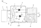
- FIG. FIG. 2 is a circuit configuration diagram schematically showing an example of the circuit configuration of the refrigeration cycle apparatus 100 according to Embodiment 2 of the present invention.
- the refrigeration cycle apparatus 100 will be described with reference to FIG.
- an air conditioner will be described as an example of the refrigeration cycle apparatus 100.
- the flow of a fluid such as a refrigerant or water is indicated by an arrow.
- fluid such as refrigerant or water supplied from the heat source device c to the distributor e is collectively referred to as fluid.
- the refrigeration cycle apparatus 100 includes the distributor e according to Embodiment 1 described above as one of its components. Specifically, as shown in FIG. 1, the refrigeration cycle apparatus 100 includes one heat source machine c, a plurality of load side machines A (load side machine a and load side machine b), a distributor e, ,have.
- FIG. 1 shows an example in which the number of heat source devices c is one, but the number of heat source devices c is not particularly limited, and a plurality of heat source devices c are connected in series or in parallel to the distributor e. You may make it provide.
- FIG. 1 shows an example in which the load side machine A and the load side machine b are connected as the load side machine A, but three or more load side machines are connected to the distributor e. May be connected in parallel.
- the heat source unit c is used as, for example, an outdoor unit or an outdoor unit according to the use of the refrigeration cycle apparatus 100, and supplies a heat source to the load side unit A via a fluid.
- This heat source device c is the fluid supply side described in the first embodiment.
- the heat source device c houses a compressor, an expansion device, a heat source side heat exchanger, a blower, and the like.
- the heat source is stored in a refrigerant that is a fluid and is supplied from the heat source unit c to the load side unit A.
- another heat exchanger may be provided in the heat source machine c in addition to the heat source side heat exchanger, and the heat source may be indirectly supplied to the load side machine A.
- the heat source is stored in water as a fluid and supplied to the load side machine A. That is, the heat source stored in the refrigerant by the heat source device c may be transmitted to another fluid such as water via another heat exchanger, and this fluid may be supplied to the load side device A.
- a pump that circulates water or antifreeze liquid is accommodated in the heat source device c as a heat medium transport device instead of a blower.
- the load-side unit A is used as, for example, an indoor unit, an indoor unit, or a hot water supply unit according to the use of the refrigeration cycle apparatus 100, and is air or a load-side target by a heat source supplied from the heat source unit c via a fluid. Water or the like is heated or cooled.
- the load side machine A is the fluid distribution side described in the first embodiment.
- the load side machine A accommodates a load side heat exchanger, a blower, and the like. Depending on the mode of the load side heat exchanger, a pump that circulates water or antifreeze instead of a blower is accommodated in the load side machine A as a heat transfer device.
- the load-side heat exchanger accommodated in the load-side machine a is referred to as a load-side heat exchanger a1
- the load-side heat exchanger accommodated in the load-side machine b is referred to as a load-side heat exchanger b1.
- the load side machine A will be referred to as a load side machine A.
- the distributor e is connected between the heat source machine c and the load side machine A, and distributes and circulates the fluid supplied from the heat source machine c to each of the load side machines A.
- the configuration of the distributor e is as described in the first embodiment.
- the fluid flowing through the first forward pipe 1a-1 flows into the load-side heat exchanger a1 of the load-side machine a, and the heat medium such as air or water that is the load-side target is exchanged in the load-side heat exchanger a1 by heat exchange. Warm or cool.
- the fluid flowing through the first forward pipe 1a-2 flows into the load-side heat exchanger b1 of the load-side machine b, and in the load-side heat exchanger b1, the heat medium such as air or water that is the load-side target is exchanged by heat exchange. Warm or cool.
- the fluid that exchanges heat with the heat medium in the load side heat exchanger a1 and the load side heat exchanger b1 flows out of the load side machine a and the load side machine b.
- the fluid flowing out from the load side machine a flows through the first return pipe 2a-1 and into the return side header 2 of the distributor e.
- the fluid flowing out from the load side machine b passes through the first return pipe 2a-2 and flows into the return side header 2 of the distributor e.
- the fluids that flow into the return header 2 are merged and returned to the heat source machine c through the second return pipe 2b.
- the fluid returning from the load side machine a flows through the first return pipe 2a-1 and flows into the return side header 2.
- the fluid flowing into the return header 2 is guided to the second return pipe 2b located immediately after the first return pipe 2a-1, that is, on the opposite side of the first return pipe 2a-1. And it will be returned to the heat source machine c. That is, according to the distributor e, the fluid that has flowed into the return header 2 via the first return pipe 2a-1 returns to the heat source unit c via the second return pipe 2b.
- the fluid flows smoothly at, and the fluid does not short cycle in the circuit of the load side machine a.
- the fluid returning from the load side machine b flows through the first return pipe 2a-2 and flows into the return side header 2.
- the fluid flowing into the return header 2 is guided to the second return pipe 2b located on the opposite side of the first return pipe 2a-2. And it will be returned to the heat source machine c. That is, according to the distributor e, the fluid flowing into the return header 2 via the first return pipe 2a-2 also returns to the heat source device c via the second return pipe 2b.
- the fluid flows smoothly at, and the fluid does not short cycle in the circuit of the load side machine a.
- the fluid returning from the load side machine a and the load side machine b flows through the first return pipe 2a-1 and the first return pipe 2a-2, respectively.
- the fluid that has flowed into the return header 2 is merged and guided to the second return pipe 2b located on the opposite side of the first return pipe 2a-1 and the first return pipe 2a-2. And it will be returned to the heat source machine c. Therefore, according to the distributor e, the fluid merged in the return side header 2 smoothly returns to the heat source unit c through the second return pipe 2b, so that the fluid is not hindered in the return side header 2, and the load The fluid does not short cycle in the circuit of the side machine a.
- the fluid supplied from the heat source device c flows into the forward header 1 of the distributor e through the second forward pipe 1b.
- the fluid flowing into the outgoing header 1 is guided to the first outgoing pipe 1a-1. That is, in this case, only the pump 5a is driven and the pump 5b is stopped. Therefore, the fluid flowing into the forward header 1 is guided only to the first forward pipe 1a-1.
- the fluid flowing through the first forward pipe 1a-1 flows into the load-side heat exchanger a1 of the load-side machine a, and the heat medium such as air or water that is the load-side target is exchanged in the load-side heat exchanger a1 by heat exchange. Warm or cool.
- the fluid exchanged with the heat medium in the load side heat exchanger a1 flows out of the load side machine a.
- the fluid flowing out from the load side machine a flows through the first return pipe 2a-1 and into the return side header 2 of the distributor e.
- the fluid flowing into the return header 2 is returned to the heat source machine c through the second return pipe 2b.
- connection position of the second return pipe 2b is the first return pipe 2a-1 and the first return pipe 2a. Since the position is closer to the forward header 1 than the connection position of -2, it is possible to prevent the backflow of fluid to the unused load side machine.
- the load side machine b is a load side machine which is frequently used and frequently opens and closes the circuit
- the usage frequency of the load side machine A is set when the refrigeration cycle apparatus 100 is installed.
- the high usage frequency means that it is assumed in advance that the usage frequency increases according to the use of each connected load-side unit.
- the usage of the load side machine includes air conditioning in a living room, air conditioning in a warehouse, air conditioning in a common space, floor heating, hot water supply and the like.
- the first return pipe 2 a-2 connecting the load side machine “b” and the return side header 2 is connected to a position farthest from the second return pipe 2 b in the return side header 2.
- the distributor e since the distributor e is provided as a configuration, a short cycle can be performed in a circuit on the load side unit with a simple piping configuration that does not require components such as a check valve. It can be prevented from generating. Further, according to the refrigeration cycle apparatus 100, since the inner diameter of the bypass pipe 3 is smaller than the inner diameter of the forward header 1 and the return header 2, a short cycle of fluid is generated in the circuit on the load side. You can avoid it. Furthermore, according to the refrigeration cycle apparatus 100, since the second return pipe 2b is connected to the position closest to the heat source device c side, the load side device side can be connected even during operation when the entire load side device is not used. There is no fluid backflow into the circuit.
Landscapes
- Engineering & Computer Science (AREA)
- Physics & Mathematics (AREA)
- Thermal Sciences (AREA)
- Mechanical Engineering (AREA)
- General Engineering & Computer Science (AREA)
- Chemical & Material Sciences (AREA)
- Combustion & Propulsion (AREA)
- Other Air-Conditioning Systems (AREA)
- Steam Or Hot-Water Central Heating Systems (AREA)
Abstract
Le distributeur selon la présente invention comporte un collecteur de côté sortant auquel une pluralité de tuyaux de sortie sont connectés, et un collecteur de côté de retour auquel une pluralité de tuyaux de retour sont connectés. La pluralité de tuyaux de sortie comprend au moins deux premiers tuyaux de sortie reliés à un côté de distribution de fluide, et un second tuyau de sortie relié à un côté d'alimentation en fluide. La pluralité de tuyaux de retour comprend au moins deux premiers tuyaux de retour reliés au côté de distribution de fluide, et un second tuyau de retour relié au côté d'alimentation en fluide. Le second tuyau de retour est relié à un côté qui est situé en aval dans le sens d'écoulement du fluide revenant au moins des deux premiers tuyaux de retour, et qui est opposée dans le sens longitudinale du collecteur côté retour à partir des positions où au moins les deux premiers tuyaux de retour sont connectés au collecteur côté retour.
Priority Applications (4)
| Application Number | Priority Date | Filing Date | Title |
|---|---|---|---|
| JP2018530218A JP6599010B2 (ja) | 2016-07-25 | 2016-07-25 | 分配器及び冷凍サイクル装置 |
| EP16904240.5A EP3309476B1 (fr) | 2016-07-25 | 2016-07-25 | Distributeur et appareil à cycle frigorifique |
| PCT/JP2016/071766 WO2018020557A1 (fr) | 2016-07-25 | 2016-07-25 | Distributeur et appareil à cycle frigorifique |
| CN201690000890.9U CN207797467U (zh) | 2016-07-25 | 2016-07-25 | 分配器以及制冷循环装置 |
Applications Claiming Priority (1)
| Application Number | Priority Date | Filing Date | Title |
|---|---|---|---|
| PCT/JP2016/071766 WO2018020557A1 (fr) | 2016-07-25 | 2016-07-25 | Distributeur et appareil à cycle frigorifique |
Publications (1)
| Publication Number | Publication Date |
|---|---|
| WO2018020557A1 true WO2018020557A1 (fr) | 2018-02-01 |
Family
ID=61016937
Family Applications (1)
| Application Number | Title | Priority Date | Filing Date |
|---|---|---|---|
| PCT/JP2016/071766 WO2018020557A1 (fr) | 2016-07-25 | 2016-07-25 | Distributeur et appareil à cycle frigorifique |
Country Status (4)
| Country | Link |
|---|---|
| EP (1) | EP3309476B1 (fr) |
| JP (1) | JP6599010B2 (fr) |
| CN (1) | CN207797467U (fr) |
| WO (1) | WO2018020557A1 (fr) |
Cited By (1)
| Publication number | Priority date | Publication date | Assignee | Title |
|---|---|---|---|---|
| KR102185948B1 (ko) * | 2019-05-29 | 2020-12-03 | 한국에너지기술연구원 | 양방향 열에너지 제어 시스템 |
Citations (6)
| Publication number | Priority date | Publication date | Assignee | Title |
|---|---|---|---|---|
| JPS5510946U (fr) * | 1978-07-06 | 1980-01-24 | ||
| JPS5716708U (fr) | 1980-07-04 | 1982-01-28 | ||
| JPH03274327A (ja) * | 1990-03-22 | 1991-12-05 | Matsushita Electric Ind Co Ltd | 温水暖房装置 |
| JP2002250526A (ja) * | 2001-02-23 | 2002-09-06 | Corona Corp | 温水システムの圧力異常検知装置 |
| JP2005069368A (ja) * | 2003-08-25 | 2005-03-17 | Rinnai Corp | 温水配管構造 |
| JP2005127586A (ja) * | 2003-10-23 | 2005-05-19 | Yamatake Corp | 1次ポンプ方式熱源変流量制御システムおよび1次ポンプ最低流量確保方法 |
Family Cites Families (4)
| Publication number | Priority date | Publication date | Assignee | Title |
|---|---|---|---|---|
| US6092734A (en) * | 1995-08-29 | 2000-07-25 | Monard (Research & Development) Limited | Manifold for connecting circuits of a central heating system |
| NL1025535C2 (nl) * | 2004-02-20 | 2004-12-28 | J K Beheer B V | Verdeler in een vloerverwarmingssysteem. |
| EP2014992A1 (fr) * | 2007-07-13 | 2009-01-14 | Helmut Burtscher | Répartiteur d'installations de température |
| EP3218652A1 (fr) * | 2014-11-12 | 2017-09-20 | Rea, David Patrick | Collecteur, bac tampon comprenant le collecteur et procédé pour faire fonctionner un système d'échange de chaleur |
-
2016
- 2016-07-25 CN CN201690000890.9U patent/CN207797467U/zh active Active
- 2016-07-25 JP JP2018530218A patent/JP6599010B2/ja active Active
- 2016-07-25 WO PCT/JP2016/071766 patent/WO2018020557A1/fr unknown
- 2016-07-25 EP EP16904240.5A patent/EP3309476B1/fr active Active
Patent Citations (6)
| Publication number | Priority date | Publication date | Assignee | Title |
|---|---|---|---|---|
| JPS5510946U (fr) * | 1978-07-06 | 1980-01-24 | ||
| JPS5716708U (fr) | 1980-07-04 | 1982-01-28 | ||
| JPH03274327A (ja) * | 1990-03-22 | 1991-12-05 | Matsushita Electric Ind Co Ltd | 温水暖房装置 |
| JP2002250526A (ja) * | 2001-02-23 | 2002-09-06 | Corona Corp | 温水システムの圧力異常検知装置 |
| JP2005069368A (ja) * | 2003-08-25 | 2005-03-17 | Rinnai Corp | 温水配管構造 |
| JP2005127586A (ja) * | 2003-10-23 | 2005-05-19 | Yamatake Corp | 1次ポンプ方式熱源変流量制御システムおよび1次ポンプ最低流量確保方法 |
Cited By (1)
| Publication number | Priority date | Publication date | Assignee | Title |
|---|---|---|---|---|
| KR102185948B1 (ko) * | 2019-05-29 | 2020-12-03 | 한국에너지기술연구원 | 양방향 열에너지 제어 시스템 |
Also Published As
| Publication number | Publication date |
|---|---|
| EP3309476B1 (fr) | 2019-08-28 |
| CN207797467U (zh) | 2018-08-31 |
| EP3309476A4 (fr) | 2018-06-13 |
| JPWO2018020557A1 (ja) | 2019-03-14 |
| JP6599010B2 (ja) | 2019-10-30 |
| EP3309476A1 (fr) | 2018-04-18 |
Similar Documents
| Publication | Publication Date | Title |
|---|---|---|
| AU2005258416B2 (en) | Hot water supply system | |
| JPWO2018116413A1 (ja) | 分配器、熱交換器、及び、冷凍サイクル装置 | |
| CN104813757A (zh) | 用于开关柜冷却的热交换器和相应的冷却装置 | |
| KR101168590B1 (ko) | 지열 냉난방 장치 | |
| JP5817775B2 (ja) | チラー装置 | |
| KR101568847B1 (ko) | 지중 열교환기를 포함하는 히트 펌프 시스템 | |
| KR20130030626A (ko) | 차량용 열교환기 | |
| WO2013180030A1 (fr) | Dispositif de pompe à chaleur | |
| JP6599010B2 (ja) | 分配器及び冷凍サイクル装置 | |
| EP2982924A1 (fr) | Échangeur de chaleur | |
| JP5624443B2 (ja) | 冷房装置 | |
| JP6118065B2 (ja) | 水冷式空調システム及びその運転制御方法 | |
| JP6179750B2 (ja) | ヒートポンプ式熱源機 | |
| KR101483577B1 (ko) | 급수나 급탕을 이용한 천정냉난방장치 | |
| JP6009797B2 (ja) | 暖房システム | |
| JP2020118413A (ja) | 暖房システム | |
| KR101283252B1 (ko) | 열매체 균등분할 공기조화기 | |
| JP5847337B2 (ja) | 複数温度システム | |
| KR102167090B1 (ko) | 대항류로 열교환하는 히트펌프 시스템, 이의 동작 방법 | |
| US20240044556A1 (en) | Air Conditioning, Heat Pump and Water Heating System | |
| JP2019163865A (ja) | 熱交換器及びそれを用いた冷凍システム | |
| JP2014222137A (ja) | 三流体熱交換器 | |
| JP5877324B2 (ja) | ヒートポンプユニット | |
| JP2023010567A (ja) | ヘッダ | |
| WO2016009574A1 (fr) | Système d'alimentation en eau chaude du type réservoir |
Legal Events
| Date | Code | Title | Description |
|---|---|---|---|
| 121 | Ep: the epo has been informed by wipo that ep was designated in this application |
Ref document number: 16904240 Country of ref document: EP Kind code of ref document: A1 |
|
| ENP | Entry into the national phase |
Ref document number: 2018530218 Country of ref document: JP Kind code of ref document: A |
|
| NENP | Non-entry into the national phase |
Ref country code: DE |