WO2018012408A1 - 電流測定装置 - Google Patents
電流測定装置 Download PDFInfo
- Publication number
- WO2018012408A1 WO2018012408A1 PCT/JP2017/024864 JP2017024864W WO2018012408A1 WO 2018012408 A1 WO2018012408 A1 WO 2018012408A1 JP 2017024864 W JP2017024864 W JP 2017024864W WO 2018012408 A1 WO2018012408 A1 WO 2018012408A1
- Authority
- WO
- WIPO (PCT)
- Prior art keywords
- current
- secondary battery
- control unit
- measuring device
- gain
- Prior art date
- Legal status (The legal status is an assumption and is not a legal conclusion. Google has not performed a legal analysis and makes no representation as to the accuracy of the status listed.)
- Ceased
Links
Images

Classifications
-
- G—PHYSICS
- G01—MEASURING; TESTING
- G01R—MEASURING ELECTRIC VARIABLES; MEASURING MAGNETIC VARIABLES
- G01R19/00—Arrangements for measuring currents or voltages or for indicating presence or sign thereof
-
- H—ELECTRICITY
- H01—ELECTRIC ELEMENTS
- H01M—PROCESSES OR MEANS, e.g. BATTERIES, FOR THE DIRECT CONVERSION OF CHEMICAL ENERGY INTO ELECTRICAL ENERGY
- H01M50/00—Constructional details or processes of manufacture of the non-active parts of electrochemical cells other than fuel cells, e.g. hybrid cells
- H01M50/50—Current conducting connections for cells or batteries
-
- G—PHYSICS
- G01—MEASURING; TESTING
- G01R—MEASURING ELECTRIC VARIABLES; MEASURING MAGNETIC VARIABLES
- G01R19/00—Arrangements for measuring currents or voltages or for indicating presence or sign thereof
- G01R19/32—Compensating for temperature change
-
- H—ELECTRICITY
- H01—ELECTRIC ELEMENTS
- H01M—PROCESSES OR MEANS, e.g. BATTERIES, FOR THE DIRECT CONVERSION OF CHEMICAL ENERGY INTO ELECTRICAL ENERGY
- H01M10/00—Secondary cells; Manufacture thereof
- H01M10/42—Methods or arrangements for servicing or maintenance of secondary cells or secondary half-cells
- H01M10/48—Accumulators combined with arrangements for measuring, testing or indicating the condition of cells, e.g. the level or density of the electrolyte
-
- H—ELECTRICITY
- H01—ELECTRIC ELEMENTS
- H01M—PROCESSES OR MEANS, e.g. BATTERIES, FOR THE DIRECT CONVERSION OF CHEMICAL ENERGY INTO ELECTRICAL ENERGY
- H01M50/00—Constructional details or processes of manufacture of the non-active parts of electrochemical cells other than fuel cells, e.g. hybrid cells
- H01M50/50—Current conducting connections for cells or batteries
- H01M50/569—Constructional details of current conducting connections for detecting conditions inside cells or batteries, e.g. details of voltage sensing terminals
-
- Y—GENERAL TAGGING OF NEW TECHNOLOGICAL DEVELOPMENTS; GENERAL TAGGING OF CROSS-SECTIONAL TECHNOLOGIES SPANNING OVER SEVERAL SECTIONS OF THE IPC; TECHNICAL SUBJECTS COVERED BY FORMER USPC CROSS-REFERENCE ART COLLECTIONS [XRACs] AND DIGESTS
- Y02—TECHNOLOGIES OR APPLICATIONS FOR MITIGATION OR ADAPTATION AGAINST CLIMATE CHANGE
- Y02E—REDUCTION OF GREENHOUSE GAS [GHG] EMISSIONS, RELATED TO ENERGY GENERATION, TRANSMISSION OR DISTRIBUTION
- Y02E60/00—Enabling technologies; Technologies with a potential or indirect contribution to GHG emissions mitigation
- Y02E60/10—Energy storage using batteries
Definitions
- the present invention relates to a current measuring device for measuring the current of a secondary battery.
- Patent Document 1 In order to measure the current of a secondary battery such as a lithium ion battery mounted on an electric vehicle or the like, there has been a technique for calculating the current based on the voltage between bus bar terminals of the secondary battery (for example, Patent Document 1).
- a current measurement range (hereinafter, referred to as a measurement current range or a dynamic range) is fixed.
- the measurement current range is set small, the current can be measured with high accuracy, but the current exceeding the measurement current range cannot be measured.
- the measurement current range is set in accordance with the maximum discharge current value and the maximum charge current value, the measurement accuracy when the current value is small is lowered.
- an object of the present invention made in view of the above-described problems is to provide a current measuring apparatus capable of making a measurement current range variable and suppressing a decrease in measurement accuracy of a current value.
- a current measuring device is A current detection amplifier for detecting the current of the secondary battery; A control unit for controlling a gain and a reference voltage of the current detection amplifier; With The control unit may change the measurement current range on the discharge side of the secondary battery by changing the gain and the reference voltage.
- the current measurement device it is possible to change the measurement current range by changing the gain and the reference voltage of the current detection amplifier, thereby suppressing a decrease in measurement accuracy of the current value.
- the storage battery system 10 is mounted on a vehicle such as a hybrid vehicle (HEV vehicle).
- a vehicle such as a hybrid vehicle (HEV vehicle).
- the storage battery system 10 includes an alternator 12, a starter motor 13, a first secondary battery 14, a current measuring device 15, a second secondary battery 16, a load 17, a first switch 18, 2 switch 19, third switch 20, and ECM 21 (Engine (Control Module 21).
- the alternator 12, the starter motor 13, the first secondary battery 14, the second secondary battery 16, and the load 17 are connected in parallel.
- the alternator 12 is a generator and is mechanically connected to a vehicle engine.
- the alternator 12 can generate electric power by driving the engine.
- the power generated by the alternator 12 by driving the engine can be supplied to the first secondary battery 14, the second secondary battery 16, the load 17, and the vehicle auxiliary equipment by adjusting the output voltage with a regulator.
- the alternator 12 can generate power by regeneration when the vehicle is decelerated.
- the electric power regenerated by the alternator 12 can be used to charge the first secondary battery 14 and the second secondary battery 16.
- the starter motor 13 is configured to include a cell motor, for example, and receives power supply from at least one of the first secondary battery 14 and the second secondary battery 16 to start the engine of the vehicle.
- the first secondary battery 14 is a secondary battery other than a lead storage battery, such as a lithium ion battery or a nickel metal hydride battery.
- the output voltage of the first secondary battery 14 is substantially the same as the output voltage of the second secondary battery 16 and is, for example, 12V.
- the output voltage of the first secondary battery 14 may be different from the output voltage of the second secondary battery 16.
- the output voltage of the first secondary battery 14 is adjusted by the DC / DC converter so as to be substantially the same as the output voltage of the second secondary battery 16.
- the first secondary battery 14 can supply electric power to the auxiliary machine including the starter motor 13, the load 17, the ECM, and the like while the engine drive is stopped (when idling is stopped).
- the current measuring device 15 measures the current of the first secondary battery 14. Details of the current measuring device 15 will be described later.
- the second secondary battery 16 is a lead storage battery having an output voltage of a nominal voltage of 12 V, for example, and can supply power to the load 17.
- the load 17 is a load including an audio, an air conditioner, a navigation system, and the like provided in the vehicle, for example, and operates by consuming the supplied power.
- the load 17 operates by receiving power supply from the first secondary battery 14 and the second secondary battery 16 while the engine drive is stopped, and the alternator 12 and the first secondary battery 14 while the engine is driven. And the power supply from the second secondary battery 16 operates.
- the first switch 18 is a switch connected in series with the starter motor 13.
- the first switch 18 connects or disconnects the starter motor 13 in parallel with other components.
- the first switch 18 is configured by, for example, a MOSFET, but is not limited thereto.
- the first switch 18 corresponds to a switch according to the starter motor of the present invention.
- the second switch 19 is a switch connected in series with the first secondary battery 14.
- the second switch 19 connects or disconnects the first secondary battery 14 in parallel with other components.
- the second switch 19 is configured by, for example, a MOSFET, but is not limited thereto.
- the third switch 20 is a switch connected in series with the second secondary battery 16 and the load 17.
- the third switch 20 connects or disconnects the second secondary battery 16 and the load 17 in parallel with other components.
- the 3rd switch 20 is comprised by MOSFET, for example, it is not restricted to this.
- the ECM 21 controls the entire operation of the storage battery system 10.
- the ECM 21 controls the operations of the first switch 18, the second switch 19, and the third switch 20, and uses the alternator 12, the first secondary battery 14, and the second secondary battery 16. Power is supplied, and the first secondary battery 14 and the second secondary battery 16 are charged.
- the ECM 21 turns on the first switch 18.
- the ECM 21 turns on at least one of the second switch 19 and the third switch 20.
- the starter motor 13 receives power supply from at least one of the first secondary battery 14 and the second secondary battery 16 and starts the engine of the vehicle.
- FIG. 2 shows the first secondary battery 14 and the current measuring device 15 to be measured for current.
- the first secondary battery 14 includes a plurality of battery cells 141, a total positive terminal bus bar 142a, an inter-cell bus bar 142b, and a total negative terminal bus bar 142c.
- FIG. 2 shows an example in which the number of battery cells 141 is 5, the present invention is not limited to this.
- the total positive terminal bus bar 142a and the total negative terminal bus bar 142c are connected to the positive electrode and the negative electrode of the battery cells 141 at both ends, respectively.
- the inter-cell bus bar 142b electrically connects the battery cells 141 to each other.
- the current measuring device 15 includes a current detection amplifier 151 and a control unit 152.
- the current detection amplifier 151 detects a potential difference (a potential between bus bar terminals) between the positive electrode and the negative electrode of the inter-cell bus bar 142b of the first secondary battery 14, detects a current value based on the potential between the bus bar terminals, and performs control. Output to the unit 152.
- the inter-bus bar terminal potential of the inter-cell bus bar 142 b connected to the battery cell 141 to which the total positive terminal bus bar 142 a is connected is detected, but the current detection position is not limited to this.
- a potential difference between the positive electrode and the negative electrode in another arbitrary inter-cell bus bar 142b may be detected, and the current may be detected based on the bus bar terminal potential.
- the control unit 152 performs various controls related to the current measuring device 15. For example, the control unit 152 outputs the current value received from the current detection amplifier 151 to the ECM 21. The control unit 152 controls the gain and reference voltage of the current detection amplifier 151. Then, the control unit 152 changes the gain and the reference voltage under a predetermined condition, and changes the measurement current range on the discharge side of the first secondary battery 14.
- the discharge current of the first secondary battery 14 increases when the engine is started, when the engine is restarted, and when torque assist is performed. In order to measure the current in these cases, it is necessary to change the measurement current range on the discharge side of the first secondary battery 14 to be expanded. Therefore, when the start of the starter motor 13 is detected, the control unit 152 changes the gain and the reference voltage, and changes the measurement current range on the discharge side of the first secondary battery 14. On the other hand, the measurement current range on the charging side of the first secondary battery 14 is not changed. That is, the control unit 152 changes only the measurement current range on the discharge side of the first secondary battery 14.
- the control unit 152 detects the start of the starter motor 13 by receiving a signal related to the first switch 18 from the ECM 21. For example, when the first switch 18 is configured by a MOSFET, the control unit 152 receives a signal to the gate of the MOSFET from the ECM 21 to detect the start of the starter motor 13.
- the control unit 152 when the control unit 152 receives the torque assist signal from the ECM 21, the control unit 152 changes the gain and the reference voltage, and expands the measurement current range on the discharge side of the first secondary battery 14. On the other hand, the measurement current range on the charging side of the first secondary battery 14 is not changed. That is, the control unit 152 changes only the measurement current range on the discharge side of the first secondary battery 14.
- the case where the start of the starter motor 13 is detected and the case where the torque assist signal is received are also referred to as a dynamic range expansion state, and a state other than the dynamic range expansion state is also referred to as a normal state.
- the control unit 152 changes the gain and the reference voltage by switching a plurality of resistors connected to a reference power supply. Specifically, the control unit 152 switches the connection of the resistors (R1 to R6) between the reference power supply and the current detection amplifier 151 by switching ON / OFF of the switch SW1 and the switch SW2. In this way, the control unit 152 changes the gain and the reference voltage.
- a resistor R4 and a resistor R5 are connected in series to a reference power supply (here, 5V).
- the resistor R6 is connected in parallel with the resistor R5 via the switch SW2.
- the resistor R2 is connected in parallel with the resistor R5 at the subsequent stage of the resistor R4.
- the resistor R3 is connected via the switch SW1 so as to be in parallel with the resistor R5 at the subsequent stage of the resistor R4.
- the switch SW1 and the switch SW2 are configured by, for example, MOSFETs, but are not limited thereto.
- the control unit 152 turns on the switch SW1 and the switch SW2.
- the gain of the current detection amplifier 151 has the following value. (R2 ⁇ R3 / (R2 + R3)) / R1
- R1, R2, and R3 are resistance values of the respective resistance elements in FIG.
- the reference voltage of the current detection amplifier 151 has the following value.
- R4, R5, and R6 are resistance values of the respective resistance elements in FIG.
- the control unit 152 turns off the switch SW1 and the switch SW2. At this time, the gain of the current detection amplifier 151 has the following value. R2 / R1
- the reference voltage of the current detection amplifier 151 has the following value. 5 [V] ⁇ R5 / (R4 + R5)
- FIG. 3 is a diagram illustrating a measurement current range in a normal state of the current measurement device according to the embodiment of the present invention.
- the vertical axis represents the bus bar terminal potential (V).
- the horizontal axis represents the current value (I) detected by the current detection amplifier 151 and output to the control unit 152.
- the bus bar terminal potential varies between Va and Vb.
- a current value is measured in a one-to-one linear relationship with the potential between the bus bar terminals, and the measurement current range is Ia to Ib.
- the current measuring device 15 detects that the current value is Ia. As shown in FIG. 3, since Ia is a negative value, the first secondary battery 14 is discharged. When the potential between the bus bar terminals is Vb, the current measuring device 15 detects that the current value is Ib. As shown in FIG. 3, since Ib is a positive value, the first secondary battery 14 is charged. When the potential between the bus bar terminals is V 0 , the current measuring device 15 detects that the current value is 0.
- FIG. 4 is a figure which shows the measurement current range of the dynamic range expansion state of the current measurement apparatus which concerns on one Embodiment of this invention. Since the gain is changed from the normal state, the slope of the graph is reduced from that in the normal state. Since the reference voltage is changed from the normal state, the graph is translated in the negative direction of the horizontal axis. Therefore, in the example shown in FIG. 4, the measurement current range on the discharge side of the first secondary battery 14 is Ic to Ib.
- Ic ⁇ Ia. That is, at the time of engine start or torque assist of the current measuring device, the measurement current range on the discharge side of the secondary battery is expanded. Specifically, Ic is about several times (for example, about four times) Ia.
- the current measuring device 15 detects that the current value is Ic.
- the current measuring device 15 detects that the current value is Ib.
- the bus bar terminal potential is V 0 ′, the current measuring device 15 detects that the current value is 0. Since the slopes of the graphs are different between FIGS. 3 and 4, V 0 and V 0 ′ are different.
- the control unit 152 corrects the current value detected by the current detection amplifier 151 based on the temperature detected by the temperature sensor 143. Specifically, it is preferable that the resistance value of the inter-cell bus bar 142b at each temperature is acquired in advance and the current value is corrected based on the resistance value.
- control unit 152 determines whether it is in a normal state by detecting the start of the starter motor or the start of torque assist (step S10). If it is in the normal state, the process proceeds to step S20.
- control unit 152 turns on the switch SW1 and the switch SW2 (step S20).
- control unit 152 measures the current flowing through the first secondary battery 14 (step S30). That is, the control unit 152 receives the current value detected by the current detection amplifier 151 in the measurement current range in the normal state, and outputs the current value to the ECM 21.
- Step S10 when it is not the normal state in Step S10 (that is, when the dynamic range is expanded), the control unit 152 turns off the switch SW1 and the switch SW2 (Step S40). And it progresses to step S30 and the electric current which flows into the 1st secondary battery 14 is measured. That is, the control unit 152 receives the current value detected by the current detection amplifier 151 in the measurement current range in the dynamic range expansion state, and outputs the current value to the ECM 21.
- the measurement current range is made variable by changing the gain and the reference voltage of the current detection amplifier 151, thereby suppressing the decrease in the measurement accuracy of the current value. be able to.
- the discharge current of the first secondary battery 14 increases when the engine is started, when the engine is restarted, and when torque assist is performed.
- the current measuring device 15 expands only the measurement current range on the discharge side, it is possible to expand the measurement current range as much as necessary and suppress a decrease in measurement accuracy of the current value. Since the current value obtained in this manner is highly accurate, charge / discharge control of the first secondary battery 14 and prevention of overcharge and overdischarge can be appropriately performed.
Landscapes
- Chemical & Material Sciences (AREA)
- Chemical Kinetics & Catalysis (AREA)
- Electrochemistry (AREA)
- General Chemical & Material Sciences (AREA)
- Engineering & Computer Science (AREA)
- Manufacturing & Machinery (AREA)
- Physics & Mathematics (AREA)
- General Physics & Mathematics (AREA)
- Secondary Cells (AREA)
- Tests Of Electric Status Of Batteries (AREA)
- Measurement Of Current Or Voltage (AREA)
- Connection Of Batteries Or Terminals (AREA)
Abstract
測定電流範囲を可変として、電流値の測定精度の低下を抑制することができる電流測定装置を提供する。二次電池(14)のバスバー端子間電位に基づき電流を検出する電流検出アンプ(151)と、電流検出アンプ(151)のゲイン及びリファレンス電圧を制御する制御部(152)と、を備え、制御部(152)は、ゲイン及びリファレンス電圧を変更し、二次電池(14)の放電側の測定電流範囲を変更する。
Description
本出願は、日本国特許出願2016-136899号(2016年7月11日出願)の優先権を主張するものであり、当該出願の開示全体を、ここに参照のために取り込む。
本発明は、二次電池の電流を測定する電流測定装置に関する。
電気自動車等に搭載されるリチウムイオン電池等の二次電池の電流を測定するために、二次電池のバスバー端子間の電圧に基づき電流を算出する技術があった(例えば特許文献1)。
しかしながら、従来の技術では、電流を測定する範囲(以下、測定電流範囲、又はダイナミックレンジという)が固定されていた。測定電流範囲を小さく設定した場合は高精度で電流が測定できるものの、測定電流範囲を超える電流を測定することはできない。一方、最大の放電電流値及び最大の充電電流値に合わせて測定電流範囲を設定した場合、電流値が小さい場合の測定精度が低下してしまっていた。
従って、上記のような問題点に鑑みてなされた本発明の目的は、測定電流範囲を可変として、電流値の測定精度の低下を抑制することができる電流測定装置を提供することにある。
上記課題を解決するために本発明の一実施形態に係る電流測定装置は、
二次電池の電流を検出する電流検出アンプと、
前記電流検出アンプのゲイン及びリファレンス電圧を制御する制御部と、
を備え、
前記制御部は、前記ゲイン及び前記リファレンス電圧を変更し、前記二次電池の放電側の測定電流範囲を変更することを特徴とする。
二次電池の電流を検出する電流検出アンプと、
前記電流検出アンプのゲイン及びリファレンス電圧を制御する制御部と、
を備え、
前記制御部は、前記ゲイン及び前記リファレンス電圧を変更し、前記二次電池の放電側の測定電流範囲を変更することを特徴とする。
本発明の一実施形態に係る電流測定装置によれば、電流検出アンプのゲイン及びリファレンス電圧を変更することにより測定電流範囲を可変として、電流値の測定精度の低下を抑制することができる。
以下、本発明の実施の形態について説明する。
(実施の形態)
はじめに図1を参照して、本発明の実施の形態に係る電流測定装置を含む蓄電池システム10の概略構成について説明する。蓄電池システム10は、例えばハイブリッド車(HEV車)等の車両に搭載される。
はじめに図1を参照して、本発明の実施の形態に係る電流測定装置を含む蓄電池システム10の概略構成について説明する。蓄電池システム10は、例えばハイブリッド車(HEV車)等の車両に搭載される。
蓄電池システム10は、オルタネータ12と、スタータモータ13と、第1の二次電池14と、電流測定装置15と、第2の二次電池16と、負荷17と、第1のスイッチ18と、第2のスイッチ19と、第3のスイッチ20と、ECM21(Engine Control Module21)と、を備える。オルタネータ12、スタータモータ13、第1の二次電池14、第2の二次電池16、及び負荷17は、並列に接続される。
オルタネータ12は、発電機であって、車両のエンジンに機械的に接続される。オルタネータ12は、エンジンの駆動によって発電可能である。オルタネータ12がエンジンの駆動によって発電した電力は、レギュレータで出力電圧を調整されて、第1の二次電池14、第2の二次電池16、負荷17、及び車両の補機に供給され得る。またオルタネータ12は、車両の減速時等に回生によって発電可能である。オルタネータ12が回生発電した電力は、第1の二次電池14及び第2の二次電池16の充電に使用され得る。
スタータモータ13は、例えばセルモータを含んで構成され、第1の二次電池14及び第2の二次電池16の少なくとも一方からの電力供給を受けて、車両のエンジンを始動させる。
第1の二次電池14は、例えばリチウムイオン電池やニッケル水素電池等、鉛蓄電池以外の二次電池である。本実施形態において、第1の二次電池14の出力電圧は、第2の二次電池16の出力電圧と略同一であって、例えば12Vである。或いは、第1の二次電池14の出力電圧は、第2の二次電池16の出力電圧と異なってもよい。かかる場合、第1の二次電池14の出力電圧は、DC/DCコンバータによって、第2の二次電池16の出力電圧と略同一となるように調整される。また第1の二次電池14は、エンジン駆動の停止中(アイドリングの停止中)に、スタータモータ13を含む補機、負荷17、及びECM等に対して電力を供給可能である。
電流測定装置15は、第1の二次電池14の電流を測定する。電流測定装置15の詳細については後述する。
第2の二次電池16は、例えば公称電圧12Vの出力電圧を有する鉛蓄電池であって、負荷17に対して電力を供給可能である。
負荷17は、例えば車両に備えられたオーディオ、エアコン、及びナビゲーションシステム等を含む負荷であって、供給された電力を消費して動作する。負荷17は、エンジン駆動の停止中に第1の二次電池14、及び第2の二次電池16からの電力供給を受けて動作し、エンジン駆動中にオルタネータ12、第1の二次電池14、及び第2の二次電池16からの電力供給を受けて動作する。
第1のスイッチ18は、スタータモータ13と直列に接続されるスイッチである。第1のスイッチ18は、スタータモータ13を他の構成要素と並列に接続し又は切り離す。第1のスイッチ18は、例えばMOSFETにより構成するがこれに限られない。なお第1のスイッチ18は本発明のスタータモータに係るスイッチに対応する。
第2のスイッチ19は、第1の二次電池14と直列に接続されるスイッチである。第2のスイッチ19は、第1の二次電池14を他の構成要素と並列に接続し又は切り離す。第2のスイッチ19は、例えばMOSFETにより構成するがこれに限られない。
第3のスイッチ20は、第2の二次電池16及び負荷17と直列に接続されるスイッチである。第3のスイッチ20は、第2の二次電池16及び負荷17を他の構成要素と並列に接続し又は切り離す。第3のスイッチ20は、例えばMOSFETにより構成するがこれに限られない。
ECM21は、蓄電池システム10の動作全体を制御する。例えばECM21は、第1のスイッチ18、第2のスイッチ19、及び第3のスイッチ20の動作をそれぞれ制御して、オルタネータ12、第1の二次電池14、及び第2の二次電池16による電力供給、並びに第1の二次電池14及び第2の二次電池16の充電を行なう。例えば蓄電池システム10が搭載された車両の運転者エンジンを始動しようとする場合、ECM21は、第1のスイッチ18をON状態とする。またECM21は、第2のスイッチ19、及び第3のスイッチ20の少なくとも一方をON状態とする。これによりスタータモータ13は、第1の二次電池14及び第2の二次電池16の少なくとも一方からの電力供給を受けて、車両のエンジンを始動させる。
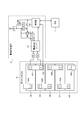
次に図2を参照して、電流測定装置15について詳細に説明する。図2は、電流を測定する対象の第1の二次電池14及び電流測定装置15を示している。
第1の二次電池14は、複数の電池セル141、総プラス端子バスバー142a、セル間バスバー142b、総マイナス端子バスバー142cを備える。図2では、電池セル141の個数は5である例を示しているがこれに限定されない。総プラス端子バスバー142a及び総マイナス端子バスバー142cは、それぞれ両端の電池セル141の正極及び負極に接続される。セル間バスバー142bは、電池セル141同士を電気的に接続する。
電流測定装置15は、電流検出アンプ151と、制御部152とを備える。電流検出アンプ151は、第1の二次電池14のセル間バスバー142bの正極及び負極の間の電位差(バスバー端子間電位)を検出し、当該バスバー端子間電位に基づき電流値を検出し、制御部152に出力する。なお図2では、総プラス端子バスバー142aが接続された電池セル141に接続されたセル間バスバー142bのバスバー端子間電位を検出しているが、電流の検出位置はこれに限られない。他の任意のセル間バスバー142bにおける正極及び負極の間の電位差を検出して、当該バスバー端子間電位に基づき電流を検出するようにしてもよい。
制御部152は、電流測定装置15に係る各種制御を行なう。例えば制御部152は、電流検出アンプ151から受けた電流値を、ECM21に出力する。また制御部152は、電流検出アンプ151のゲイン及びリファレンス電圧を制御する。そして制御部152は、所定条件下、ゲイン及びリファレンス電圧を変更し、第1の二次電池14の放電側の測定電流範囲を変更する。
具体的には、エンジンの始動時、エンジンの再始動時、及びトルクアシスト時において、第1の二次電池14の放電電流が増大する。これらの場合において電流を測定するためには、第1の二次電池14の放電側の測定電流範囲を拡大するように変更する必要がある。そこで制御部152は、スタータモータ13の始動を検出した場合、ゲイン及びリファレンス電圧を変更し、第1の二次電池14の放電側の測定電流範囲を変更する。一方で第1の二次電池14の充電側の測定電流範囲を変更しない。すなわち、制御部152は、第1の二次電池14の放電側の測定電流範囲のみを変更する。制御部152は、ECM21から第1のスイッチ18に係る信号を受信することにより、スタータモータ13の始動を検出する。例えば第1のスイッチ18をMOSFETにより構成する場合、MOSFETのゲートへの信号を制御部152がECM21から受信することにより、スタータモータ13の始動を検出する。
また制御部152は、ECM21からトルクアシスト信号を受信した場合、前記ゲイン及びリファレンス電圧を変更し、第1の二次電池14の放電側の測定電流範囲を拡大する。一方、第1の二次電池14の充電側の測定電流範囲を変更しない。すなわち、制御部152は、第1の二次電池14の放電側の測定電流範囲のみを変更する。以下、スタータモータ13の始動を検出した場合、及びトルクアシスト信号を受信した場合を、ダイナミックレンジ拡大状態ともいい、ダイナミックレンジ拡大状態以外を、通常状態ともいう。
ここで制御部152は、リファレンス電源に接続された複数の抵抗を切り替えることにより、前記ゲイン及び前記リファレンス電圧を変更する。具体的には制御部152は、スイッチSW1及びスイッチSW2のON/OFFを切り替えることにより、リファレンス電源と電流検出アンプ151との間の抵抗(R1~R6)の接続を切り替える。このようにして制御部152は、ゲイン及びリファレンス電圧を変更する。図2に示すように、リファレンス電源(ここでは5V)には抵抗R4及び抵抗R5が直列に接続される。また抵抗R6は、スイッチSW2を介して抵抗R5と並列に接続される。抵抗R2は抵抗R4の後段において抵抗R5と並列になるように接続される。抵抗R3は抵抗R4の後段において抵抗R5と並列になるように、スイッチSW1を介して接続される。スイッチSW1及びスイッチSW2は、例えばMOSFETにより構成するがこれに限られない。
通常状態では、制御部152は、スイッチSW1及びスイッチSW2をそれぞれON状態にする。このとき電流検出アンプ151のゲインは、以下の値となる。
(R2×R3/(R2+R3))/R1
なお、R1、R2、及びR3は、それぞれ図2における各抵抗素子の抵抗値である。
(R2×R3/(R2+R3))/R1
なお、R1、R2、及びR3は、それぞれ図2における各抵抗素子の抵抗値である。
また、通常状態において電流検出アンプ151のリファレンス電圧は、以下の値となる。
5[V]×(R5×R6/(R5+R6))/(R4+R5×R6/(R5+R6))
なお、R4、R5、及びR6は、それぞれ図2における各抵抗素子の抵抗値である。
5[V]×(R5×R6/(R5+R6))/(R4+R5×R6/(R5+R6))
なお、R4、R5、及びR6は、それぞれ図2における各抵抗素子の抵抗値である。
一方、ダイナミックレンジ拡大状態では、制御部152は、スイッチSW1及びスイッチSW2をそれぞれOFF状態にする。このとき、電流検出アンプ151のゲインは、以下の値となる。
R2/R1
R2/R1
また、ダイナミックレンジ拡大状態において電流検出アンプ151のリファレンス電圧は、以下の値となる。
5[V]×R5/(R4+R5)
5[V]×R5/(R4+R5)
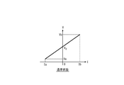
このようにして、制御部152は、スイッチSW1及びスイッチSW2により電流検出アンプ151のゲイン及びリファレンス電圧を変更し、第1の二次電池14の放電側の測定電流範囲を変更する。図3は、本発明の一実施形態に係る電流測定装置の通常状態の測定電流範囲を示す図である。縦軸はバスバー端子間電位(V)である。横軸は、電流検出アンプ151が検出して制御部152に出力する電流値(I)である。バスバー端子間電位はVa~Vbの間で変動する。当該バスバー端子間電位に一対一に線形に対応付けて電流値が測定され、測定電流範囲はIa~Ibである。バスバー端子間電位がVaである場合、電流測定装置15は、電流値がIaであると検出する。図3に示すようにIaは負の値であるため、第1の二次電池14は放電している。また、バスバー端子間電位がVbである場合、電流測定装置15は、電流値がIbであると検出する。図3に示すようにIbは正の値であるため、第1の二次電池14は充電されている。バスバー端子間電位がV0である場合、電流測定装置15は、電流値が0であると検出する。
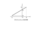
一方で図4は、本発明の一実施形態に係る電流測定装置のダイナミックレンジ拡大状態の測定電流範囲を示す図である。ゲインが通常状態から変更されるため、グラフの傾きが通常状態よりも減少する。またリファレンス電圧が通常状態から変更されるため、グラフが横軸の負の方向に平行移動する。そのため図4に示す例では第1の二次電池14の放電側の測定電流範囲は、Ic~Ibとなる。ここでIc<Iaである。すなわち、電流測定装置のエンジン始動時又はトルクアシスト時においては、二次電池の放電側の測定電流範囲を拡大させている。具体的にはIcはIaの数倍程度(例えば4倍程度)である。バスバー端子間電位がVaである場合、電流測定装置15は、電流値がIcであると検出する。また、バスバー端子間電位がVbである場合、電流測定装置15は、電流値がIbであると検出する。バスバー端子間電位がV0’である場合、電流測定装置15は、電流値が0であると検出する。グラフの傾きが図3及び図4で異なるため、V0とV0’とは相違する。
好適には、図2に示すように、バスバー端子間電位を検出する対象のセル間バスバー142bに、温度センサ143を設けることが好ましい。セル間バスバー142bは温度変化によって抵抗値が変化する。そのため制御部152は、温度センサ143が検出した温度に基づき、電流検出アンプ151が検出した電流値を補正する。具体的には各温度におけるセル間バスバー142bの抵抗値を予め取得し、当該抵抗値に基づき電流値を補正することが好ましい。
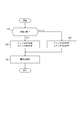
次に、本発明の一実施形態に係る電流測定装置15について、図5に示すフローチャートによりその動作を説明する。
はじめに制御部152は、スタータモータの始動、又はトルクアシストの始動を検出することにより、通常状態か否かを判定する(ステップS10)。通常状態である場合、ステップS20に進む。
次に制御部152は、スイッチSW1及びスイッチSW2をそれぞれON状態にする(ステップS20)。
続いて制御部152は、第1の二次電池14に流れる電流を測定する(ステップS30)。すなわち、制御部152は、通常状態の測定電流範囲で電流検出アンプ151が検出した電流値を受け取り、当該電流値をECM21に出力する。
一方、ステップS10において通常状態で無い場合(すなわち、ダイナミックレンジ拡大状態である場合)、制御部152は、スイッチSW1及びスイッチSW2をそれぞれOFF状態にする(ステップS40)。そしてステップS30に進み、第1の二次電池14に流れる電流を測定する。すなわち、制御部152は、ダイナミックレンジ拡大状態の測定電流範囲で電流検出アンプ151が検出した電流値を受け取り、当該電流値をECM21に出力する。
このように本発明の一実施形態に係る電流測定装置15によれば、電流検出アンプ151のゲイン及びリファレンス電圧を変更することにより測定電流範囲を可変として、電流値の測定精度の低下を抑制することができる。特に、エンジンの始動時、エンジンの再始動時、及びトルクアシスト時において、第1の二次電池14の放電電流が増大する。この場合において電流測定装置15は、放電側の測定電流範囲のみを拡大しているため、必要なだけ測定電流範囲を拡大し、電流値の測定精度の低下を抑制することが可能となる。このようにして得られた電流値は高精度であるため、第1の二次電池14の充放電制御や、過充電、過放電の防止を適切に行なうことができる。
本発明を諸図面や実施例に基づき説明してきたが、当業者であれば本開示に基づき種々の変形や修正を行うことが容易であることに注意されたい。従って、これらの変形や修正は本発明の範囲に含まれることに留意されたい。例えば、各手段、各ステップ等に含まれる機能等は論理的に矛盾しないように再配置可能であり、複数の手段やステップ等を1つに組み合わせたり、或いは分割したりすることが可能である。
10 蓄電池システム
12 オルタネータ
13 スタータモータ
14 第1の二次電池
15 電流測定装置
16 第2の二次電池
17 負荷
18 第1のスイッチ
19 第2のスイッチ
20 第3のスイッチ
21 ECM
141 電池セル
142a 総プラス端子バスバー
142b セル間バスバー
142c 総マイナス端子バスバー
143 温度センサ
151 電流検出アンプ
152 制御部
12 オルタネータ
13 スタータモータ
14 第1の二次電池
15 電流測定装置
16 第2の二次電池
17 負荷
18 第1のスイッチ
19 第2のスイッチ
20 第3のスイッチ
21 ECM
141 電池セル
142a 総プラス端子バスバー
142b セル間バスバー
142c 総マイナス端子バスバー
143 温度センサ
151 電流検出アンプ
152 制御部
Claims (15)
- 二次電池の電流を検出する電流検出アンプと、
前記電流検出アンプのゲイン及びリファレンス電圧を制御する制御部と、
を備え、
前記制御部は、前記ゲイン及び前記リファレンス電圧を変更し、前記二次電池の放電側の測定電流範囲を変更する、電流測定装置。 - 前記制御部は、スタータモータの始動を検出した場合、前記ゲイン及び前記リファレンス電圧を変更し、前記二次電池の放電側の測定電流範囲を拡大する、請求項1に記載の電流測定装置。
- 前記制御部は、前記スタータモータに係るスイッチの信号を受信することによりスタータモータの始動を検出する、請求項2に記載の電流測定装置。
- 前記制御部は、トルクアシスト信号を受信した場合、前記ゲイン及び前記リファレンス電圧を変更し、前記二次電池の放電側の測定電流範囲を拡大する、請求項1に記載の電流測定装置。
- 前記制御部は、トルクアシスト信号を受信した場合、前記ゲイン及び前記リファレンス電圧を変更し、前記二次電池の放電側の測定電流範囲を拡大する、請求項2に記載の電流測定装置。
- 前記制御部は、トルクアシスト信号を受信した場合、前記ゲイン及び前記リファレンス電圧を変更し、前記二次電池の放電側の測定電流範囲を拡大する、請求項3に記載の電流測定装置。
- 前記制御部は、リファレンス電源に接続された複数の抵抗を切り替えることにより、前記ゲイン及び前記リファレンス電圧を変更することを特徴とする、請求項1に記載の電流測定装置。
- 前記制御部は、リファレンス電源に接続された複数の抵抗を切り替えることにより、前記ゲイン及び前記リファレンス電圧を変更することを特徴とする、請求項2に記載の電流測定装置。
- 前記制御部は、リファレンス電源に接続された複数の抵抗を切り替えることにより、前記ゲイン及び前記リファレンス電圧を変更することを特徴とする、請求項3に記載の電流測定装置。
- 前記制御部は、リファレンス電源に接続された複数の抵抗を切り替えることにより、前記ゲイン及び前記リファレンス電圧を変更することを特徴とする、請求項4に記載の電流測定装置。
- 前記二次電池のバスバーの温度を検出する温度センサを備え、
前記制御部は、前記温度に基づき前記電流検出アンプにより検出した前記電流を補正することを特徴とする、請求項1に記載の電流測定装置。 - 前記二次電池のバスバーの温度を検出する温度センサを備え、
前記制御部は、前記温度に基づき前記電流検出アンプにより検出した前記電流を補正することを特徴とする、請求項2に記載の電流測定装置。 - 前記二次電池のバスバーの温度を検出する温度センサを備え、
前記制御部は、前記温度に基づき前記電流検出アンプにより検出した前記電流を補正することを特徴とする、請求項3に記載の電流測定装置。 - 前記二次電池のバスバーの温度を検出する温度センサを備え、
前記制御部は、前記温度に基づき前記電流検出アンプにより検出した前記電流を補正することを特徴とする、請求項4に記載の電流測定装置。 - 前記二次電池のバスバーの温度を検出する温度センサを備え、
前記制御部は、前記温度に基づき前記電流検出アンプにより検出した前記電流を補正することを特徴とする、請求項5に記載の電流測定装置。
Applications Claiming Priority (2)
| Application Number | Priority Date | Filing Date | Title |
|---|---|---|---|
| JP2016-136899 | 2016-07-11 | ||
| JP2016136899A JP2018009808A (ja) | 2016-07-11 | 2016-07-11 | 電流測定装置 |
Publications (1)
| Publication Number | Publication Date |
|---|---|
| WO2018012408A1 true WO2018012408A1 (ja) | 2018-01-18 |
Family
ID=60951782
Family Applications (1)
| Application Number | Title | Priority Date | Filing Date |
|---|---|---|---|
| PCT/JP2017/024864 Ceased WO2018012408A1 (ja) | 2016-07-11 | 2017-07-06 | 電流測定装置 |
Country Status (2)
| Country | Link |
|---|---|
| JP (1) | JP2018009808A (ja) |
| WO (1) | WO2018012408A1 (ja) |
Citations (6)
| Publication number | Priority date | Publication date | Assignee | Title |
|---|---|---|---|---|
| JP2003188724A (ja) * | 2001-12-14 | 2003-07-04 | Sankyo Seiki Mfg Co Ltd | アナログ信号をデジタル信号に変換する方法および信号検出装置 |
| JP2005037323A (ja) * | 2003-07-18 | 2005-02-10 | Denso Corp | 電流検出器 |
| JP2007327823A (ja) * | 2006-06-07 | 2007-12-20 | Denso Corp | 車載バッテリの電流測定方法および電流測定装置 |
| WO2011010341A1 (ja) * | 2009-07-21 | 2011-01-27 | トヨタ自動車株式会社 | 電流切替装置、及び当該装置で用いられる方法 |
| JP2012078328A (ja) * | 2010-10-06 | 2012-04-19 | Yazaki Corp | バスバー温度を正確に測定できる電流検出装置 |
| JP2015194113A (ja) * | 2014-03-31 | 2015-11-05 | スズキ株式会社 | 内燃機関の制御装置 |
-
2016
- 2016-07-11 JP JP2016136899A patent/JP2018009808A/ja active Pending
-
2017
- 2017-07-06 WO PCT/JP2017/024864 patent/WO2018012408A1/ja not_active Ceased
Patent Citations (6)
| Publication number | Priority date | Publication date | Assignee | Title |
|---|---|---|---|---|
| JP2003188724A (ja) * | 2001-12-14 | 2003-07-04 | Sankyo Seiki Mfg Co Ltd | アナログ信号をデジタル信号に変換する方法および信号検出装置 |
| JP2005037323A (ja) * | 2003-07-18 | 2005-02-10 | Denso Corp | 電流検出器 |
| JP2007327823A (ja) * | 2006-06-07 | 2007-12-20 | Denso Corp | 車載バッテリの電流測定方法および電流測定装置 |
| WO2011010341A1 (ja) * | 2009-07-21 | 2011-01-27 | トヨタ自動車株式会社 | 電流切替装置、及び当該装置で用いられる方法 |
| JP2012078328A (ja) * | 2010-10-06 | 2012-04-19 | Yazaki Corp | バスバー温度を正確に測定できる電流検出装置 |
| JP2015194113A (ja) * | 2014-03-31 | 2015-11-05 | スズキ株式会社 | 内燃機関の制御装置 |
Also Published As
| Publication number | Publication date |
|---|---|
| JP2018009808A (ja) | 2018-01-18 |
Similar Documents
| Publication | Publication Date | Title |
|---|---|---|
| US11796600B2 (en) | Chargeable battery abnormality detection apparatus and chargeable battery abnormality detection method | |
| JP4457626B2 (ja) | 組電池の異常判定装置および組電池の異常判定方法 | |
| JP5050325B2 (ja) | 組電池用制御装置 | |
| US7573238B2 (en) | Voltage detection device and electric vehicle including voltage detection device | |
| EP3792639A1 (en) | Ground fault detection apparatus | |
| US20180093581A1 (en) | Power supply device for vehicle | |
| JP4843921B2 (ja) | 組電池の容量調整装置及び組電池の容量調整方法 | |
| CN112787367B (zh) | 电池控制装置和异常感测方法 | |
| JP2019100878A (ja) | 計測装置、蓄電装置、計測システム、オフセット誤差の計測方法 | |
| KR20030070812A (ko) | 전기 자동차용 전원 장치 | |
| JP2009216447A (ja) | 組電池の監視装置および故障診断方法 | |
| JP4821363B2 (ja) | 組電池制御装置および組電池制御方法 | |
| CN111077472A (zh) | 漏电判断系统 | |
| JP6577981B2 (ja) | 電源システム | |
| CN110361669A (zh) | 电池劣化判定装置 | |
| CN107615563A (zh) | 辅机用电池的状态判定装置和辅机用电池的状态判定方法 | |
| CN115397694B (zh) | 电池电压均衡装置 | |
| US20240235214A9 (en) | Equalization control device for battery | |
| JP2016213025A (ja) | 蓄電池システム | |
| JP2006049198A (ja) | 組電池の容量調整装置 | |
| WO2018012408A1 (ja) | 電流測定装置 | |
| JP2002277520A (ja) | モーター駆動電気機器の電流検出方法 | |
| JP2016162729A (ja) | バッテリ種別判定装置およびバッテリ種別判定方法 | |
| JP5724866B2 (ja) | 監視システムおよび監視方法 | |
| JP2012244826A (ja) | 蓄電装置 |
Legal Events
| Date | Code | Title | Description |
|---|---|---|---|
| DPE1 | Request for preliminary examination filed after expiration of 19th month from priority date (pct application filed from 20040101) | ||
| 121 | Ep: the epo has been informed by wipo that ep was designated in this application |
Ref document number: 17827536 Country of ref document: EP Kind code of ref document: A1 |
|
| NENP | Non-entry into the national phase |
Ref country code: DE |
|
| 122 | Ep: pct application non-entry in european phase |
Ref document number: 17827536 Country of ref document: EP Kind code of ref document: A1 |