WO2018008348A1 - 報知装置 - Google Patents
報知装置 Download PDFInfo
- Publication number
- WO2018008348A1 WO2018008348A1 PCT/JP2017/022062 JP2017022062W WO2018008348A1 WO 2018008348 A1 WO2018008348 A1 WO 2018008348A1 JP 2017022062 W JP2017022062 W JP 2017022062W WO 2018008348 A1 WO2018008348 A1 WO 2018008348A1
- Authority
- WO
- WIPO (PCT)
- Prior art keywords
- vehicle
- door
- state
- open
- closed state
- Prior art date
- Legal status (The legal status is an assumption and is not a legal conclusion. Google has not performed a legal analysis and makes no representation as to the accuracy of the status listed.)
- Ceased
Links
Images


Classifications
-
- B—PERFORMING OPERATIONS; TRANSPORTING
- B60—VEHICLES IN GENERAL
- B60Q—ARRANGEMENT OF SIGNALLING OR LIGHTING DEVICES, THE MOUNTING OR SUPPORTING THEREOF OR CIRCUITS THEREFOR, FOR VEHICLES IN GENERAL
- B60Q1/00—Arrangement of optical signalling or lighting devices, the mounting or supporting thereof or circuits therefor
- B60Q1/26—Arrangement of optical signalling or lighting devices, the mounting or supporting thereof or circuits therefor the devices being primarily intended to indicate the vehicle, or parts thereof, or to give signals, to other traffic
- B60Q1/32—Arrangement of optical signalling or lighting devices, the mounting or supporting thereof or circuits therefor the devices being primarily intended to indicate the vehicle, or parts thereof, or to give signals, to other traffic for indicating vehicle sides, e.g. clearance lights
- B60Q1/323—Arrangement of optical signalling or lighting devices, the mounting or supporting thereof or circuits therefor the devices being primarily intended to indicate the vehicle, or parts thereof, or to give signals, to other traffic for indicating vehicle sides, e.g. clearance lights on or for doors
- B60Q1/324—Arrangement of optical signalling or lighting devices, the mounting or supporting thereof or circuits therefor the devices being primarily intended to indicate the vehicle, or parts thereof, or to give signals, to other traffic for indicating vehicle sides, e.g. clearance lights on or for doors for signalling that a door is open or intended to be opened
-
- B—PERFORMING OPERATIONS; TRANSPORTING
- B60—VEHICLES IN GENERAL
- B60Q—ARRANGEMENT OF SIGNALLING OR LIGHTING DEVICES, THE MOUNTING OR SUPPORTING THEREOF OR CIRCUITS THEREFOR, FOR VEHICLES IN GENERAL
- B60Q1/00—Arrangement of optical signalling or lighting devices, the mounting or supporting thereof or circuits therefor
-
- B—PERFORMING OPERATIONS; TRANSPORTING
- B60—VEHICLES IN GENERAL
- B60Q—ARRANGEMENT OF SIGNALLING OR LIGHTING DEVICES, THE MOUNTING OR SUPPORTING THEREOF OR CIRCUITS THEREFOR, FOR VEHICLES IN GENERAL
- B60Q3/00—Arrangement of lighting devices for vehicle interiors; Lighting devices specially adapted for vehicle interiors
- B60Q3/50—Mounting arrangements
-
- B—PERFORMING OPERATIONS; TRANSPORTING
- B60—VEHICLES IN GENERAL
- B60Q—ARRANGEMENT OF SIGNALLING OR LIGHTING DEVICES, THE MOUNTING OR SUPPORTING THEREOF OR CIRCUITS THEREFOR, FOR VEHICLES IN GENERAL
- B60Q9/00—Arrangement or adaptation of signal devices not provided for in one of main groups B60Q1/00 - B60Q7/00, e.g. haptic signalling
-
- B—PERFORMING OPERATIONS; TRANSPORTING
- B60—VEHICLES IN GENERAL
- B60R—VEHICLES, VEHICLE FITTINGS, OR VEHICLE PARTS, NOT OTHERWISE PROVIDED FOR
- B60R25/00—Fittings or systems for preventing or indicating unauthorised use or theft of vehicles
- B60R25/30—Detection related to theft or to other events relevant to anti-theft systems
- B60R25/34—Detection related to theft or to other events relevant to anti-theft systems of conditions of vehicle components, e.g. of windows, door locks or gear selectors
-
- B—PERFORMING OPERATIONS; TRANSPORTING
- B60—VEHICLES IN GENERAL
- B60Q—ARRANGEMENT OF SIGNALLING OR LIGHTING DEVICES, THE MOUNTING OR SUPPORTING THEREOF OR CIRCUITS THEREFOR, FOR VEHICLES IN GENERAL
- B60Q3/00—Arrangement of lighting devices for vehicle interiors; Lighting devices specially adapted for vehicle interiors
- B60Q3/20—Arrangement of lighting devices for vehicle interiors; Lighting devices specially adapted for vehicle interiors for lighting specific fittings of passenger or driving compartments; mounted on specific fittings of passenger or driving compartments
- B60Q3/217—Doors, e.g. door sills; Steps
Definitions
- the present invention relates to a notification device.
- This application claims priority based on Japanese Patent Application No. 2016-133559 filed on July 5, 2016, and incorporates all the description content described in the above Japanese application.
- Patent Document 1 a light emitting diode is provided on the rear end surface of a saddle plate portion of an automobile door visor, and the light emitting diode is turned on to inform an occupant who gets off the automobile that the door is a half door, An automobile door visor for notifying a subsequent vehicle that the vehicle has opened is disclosed.
- the automobile door visor disclosed in Patent Document 1 is configured to notify an occupant outside the vehicle of the open / closed state of the vehicle door by turning on a light emitting diode provided on the rear end surface of the saddle plate portion. Since the light-emitting diode cannot be seen from the passengers in the vehicle, the passengers who have already boarded the vehicle have a problem that the open / closed state of the vehicle door cannot be confirmed. Also, passengers who get off from the driver's seat (the driver's seat and the rear seat of the driver's seat) cannot see the light emitting diodes provided on the door visor on the side opposite to the driver's seat (passenger seat). There is a problem that it is impossible to confirm the open / closed state of the vehicle door on the passenger seat side.
- This invention is made in view of such a situation, and it aims at providing the alerting
- a notification device is a notification device provided in a vehicle, and includes an interior lamp configured to allow a part of emitted light to pass through a window of the vehicle, and a door included in the vehicle.
- a detection unit that detects an open / closed state; and a control unit that controls lighting of the interior lamp in a lighting manner according to a detection result of the detection unit, and the open / closed state of the door by light emitted from the interior lamp To the inside and outside of the vehicle.
- the open / closed state of the vehicle door can be notified from both inside and outside the vehicle.
- FIG. 3 is a block diagram illustrating a configuration of a control system of the notification system according to Embodiment 1.
- FIG. 3 is a flowchart illustrating a procedure of processing executed by a body ECU in the first embodiment. It is explanatory drawing explaining the lighting example when a vehicle door opens and closes normally in the state where the driver has boarded. It is explanatory drawing explaining the lighting example when a vehicle door does not close normally.
- Embodiments of the present invention will be listed and described. Moreover, you may combine arbitrarily at least one part of embodiment described below.
- An alarm device is an alarm device provided in a vehicle, and an interior lamp configured to allow part of emitted light to pass through a window of the vehicle, and opening and closing of a door provided in the vehicle.
- a detection unit that detects a state, and a control unit that controls lighting of the interior lamp in a lighting manner according to a detection result of the detection unit, and the opening / closing state of the door is determined by light emitted from the interior lamp Notify inside and outside the car.
- the open / closed state of the door detected by the detection unit includes an open state in which the door is open and a closed state in which the door is closed
- the control unit includes the detection unit
- the lighting state of the interior lamp is made different between the open state and the closed state of the door detected by.
- the occupant can determine whether the door is open or closed by checking the lighting state of the interior lamp.
- the open / closed state of the door detected by the detection unit includes an open state in which the door is open, a closed state in which the door is completely closed, and an open state and the closed state.
- the control unit changes the lighting state of the interior lamp between the open state, the closed state, and the half door state of the door detected by the detection unit.
- the occupant can determine whether the door is open, closed, or half-door by checking the lighting state of the interior lamp. .
- the notification device is provided with the interior lamp corresponding to each of the plurality of doors provided in the vehicle, and the control unit is turned on according to a detection result relating to an open / closed state of each door. Then, lighting control of each interior lamp is performed.
- the open / closed state of each door can be determined by checking the lighting state of each interior light.
- the interior lamp is arranged so that the emitted light passes through a plurality of windows opposed in the vehicle width direction.
- the open / close state of the door provided on the opposite side of the exited door can be confirmed by the interior lamp.
- the interior lamp is disposed at a lower end portion on the vehicle interior side of a window opening provided in the door.
- the window has a first light-transmitting region provided at a lower end portion of the window, and has a light transmittance lower than that of the first light-transmitting region. And a second translucent area provided on the upper side of the translucent area.
- the interior lamp is arranged so as to face the first translucent area.
- the first light-transmitting region provided at the lower end portion of the light-transmitting member is provided.
- the light that passes through can inform the occupant who gets off the vehicle of the open / closed state of the door.
- the lighting mode includes lighting color, brightness, timing of turning on and off.
- the opening / closing state of the door can be notified to the occupant by changing the lighting mode according to the lighting color, brightness, lighting and extinguishing timing of the interior lamp.
- FIG. 1 is a schematic diagram illustrating a schematic configuration of a notification system according to the first embodiment.
- the notification system according to Embodiment 1 is a system for reporting the open / closed state of vehicle doors D1 to D4 provided in the vehicle C to both inside and outside the vehicle, and a body ECU (Electronic Control) provided inside the vehicle C Unit) 100 and interior lamps 21 to 24 controlled to be turned on by body ECU 100.
- body ECU Electronic Control
- the vehicle door D1 for the driver seat the vehicle door D2 for the right rear seat (driver seat rear seat), the vehicle door D3 for the passenger seat, and the left rear seat (rear seat of the passenger seat)
- the number of vehicle doors provided in the vehicle C is not limited to four.
- the body ECU 100 acquires the detection result from a detection unit (vehicle door opening / closing sensors 11 to 14 described later: see FIG. 4) that detects the opening / closing states of the vehicle doors D1 to D4, and responds to the opening / closing states of the vehicle doors D1 to D4.
- the lighting control of the interior lamps 21 to 24 is performed in the lighting mode.
- the interior lights 21 to 24 are, for example, light emitting devices including LEDs (Light Emitting Diodes), and are configured to be turned on and off by lighting control from the body ECU 100.
- the interior lamps 21 to 24 may be configured such that a plurality of LEDs are juxtaposed on a belt-like substrate that is long in one direction and emits light in a linear shape, and light emitted from the LEDs is diffused by a light guide plate. It may be configured to emit light in a strip shape. Further, the interior lamps 21 to 24 may be configured to emit light in a dot shape or an arbitrary shape using one or a plurality of LEDs.
- the interior lamps 21 to 24 are disposed, for example, at the lower end portion on the vehicle interior side of the window openings in the vehicle doors D1 to D4.
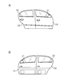
- 2 and 3 are explanatory views for explaining an arrangement example of the interior lamps 21 to 24.
- FIG. 2A shows a front view of the vehicle doors D1 and D2 viewed from the outside of the vehicle
- FIG. 2B shows a rear view of the vehicle doors D1 and D2 viewed from the inside of the vehicle
- FIG. 3 shows a partially enlarged view of the vehicle door D1 (D2) as viewed in the thickness direction.
- the interior lamps 21 and 22 are, for example, rod-shaped or strip-shaped light sources, and are arranged along the lower ends of the window openings provided in the vehicle doors D1 and D2, respectively. Therefore, when the interior lights 21 and 22 are lit, the occupant can visually recognize the lit state from outside the vehicle. Moreover, the interior lamp 21 (22) is arrange
- the interior lamps 21 and 22 are arranged as described above, the light emitted from the interior lamps 21 and 22 is transmitted through the windows of the vehicle doors D3 and D4 facing in the vehicle width direction. Even when the vehicle exits from the vehicle doors D3 and D4 on the side, the lighting state of the interior lights 21 and 22 can be visually confirmed.
- FIG. 4 is a block diagram illustrating the configuration of the control system of the notification system according to the first embodiment.
- the body ECU 100 includes a control unit 101, a storage unit 102, an input unit 103, an output unit 104, a communication unit 105, and the like.
- the control unit 101 includes, for example, a CPU (Central Processing Unit), a ROM (Read Only Memory), a RAM (Random Access Memory), and the like.
- the CPU in the control unit 101 controls the operation of the hardware included in the body ECU 100 by executing a control program stored in the ROM, and the interior of the vehicle in a lighting manner according to the open / closed state of the vehicle doors D1 to D4. A function for controlling lighting of the lamps 21 to 24 is realized.
- the RAM in the control unit 101 temporarily stores data generated during execution of the control program.
- the control unit 101 may have functions such as a timer that measures an elapsed time from when a measurement start instruction is given to when a measurement end instruction is given, and a counter that counts the number.
- the storage unit 102 is configured by a non-volatile memory such as an EEPROM (Electronically-Erasable-Programmable-Read-Only Memory), and stores information related to lighting control of the interior lights 21 to 24, for example.
- EEPROM Electrically-Erasable-Programmable-Read-Only Memory
- the input unit 103 includes interfaces for connecting the vehicle door opening / closing sensors 11 to 14, an ignition switch 15 (hereinafter referred to as IG switch 15), a seating sensor 16, and the like.
- IG switch 15 an ignition switch 15
- the input unit 103 acquires the detection result output from the vehicle door opening / closing sensors 11 to 14, the switch state output from the IG switch 15, the detection result output from the seating sensor 16, the acquired detection result Information is output to the control unit 101.
- Vehicle door open / close sensors 11 to 14 are sensors for detecting the open / closed state of the vehicle doors D1 to D4.
- the vehicle door open / close sensors 11 to 14 are provided corresponding to the vehicle doors D1 to D4, respectively, and individually detect the open / closed state of the vehicle doors D1 to D4 and output signals indicating the detection results.
- the vehicle door open / close sensors 11 to 14 may be switches that are turned on or off depending on whether the vehicle doors D1 to D4 are opened (open state) or closed (closed state), for example. It may be a sensor that detects the open state, the closed state, and the half door state between the open state and the closed state of the vehicle doors D1 to D4 by detecting the opening degree (opening degree) of D1 to D4. .
- the IG switch 15 is a push button type switch that starts a drive source (for example, an engine) of the vehicle C when the driver presses the button.
- the IG switch 15 is switched in a stepwise manner to an off position, an accessory position (ACC position), an on position, and an engine start position by an occupant pressing operation.
- a lamp control device such as a headlight, a locking mechanism for the vehicle doors D1 to D4, and the like can be operated.
- the ACC position an audio output device not shown in the figure.
- the display device and the like can be operated. In this way, only some in-vehicle devices with low power consumption can operate at the off position and the ACC position.
- many in-vehicle devices such as an air conditioner, a turn hazard, a wiper, and a meter device can operate. Further, the engine is started by igniting the spark plug at the engine start position, and returns to the on position after the engine is started.
- the seating sensor 16 is a sensor for detecting the seating state of the occupant.
- the seating sensor 16 is provided in a seat of each seat such as a driver seat, a passenger seat, and a rear seat provided in the vehicle C, for example, and the seating state of the occupant is determined for each seat based on the weight or pressure applied to the seat. Detect and output a signal indicating the detection result.
- the output unit 104 includes an interface for connecting the interior lights 21 to 24 and the like. When the output unit 104 acquires the control signal output from the control unit 101, the output unit 104 outputs the control signal to the interior lamps 21 to 24, thereby turning on or off the interior lamps 21 to 24.
- the interior lights 21 to 24 are light sources provided corresponding to the vehicle doors D1 to D4 as described above.
- the interior lights 21 to 24 are lighted in a lighting manner according to the open / closed state of the vehicle doors D1 to D4 by the lighting control from the control unit 101, and then get off the passengers seated in the vehicle and the vehicle C. The occupant is notified of the open / closed state of the vehicle doors D1 to D4.
- the communication unit 105 includes a CAN (Controller Area Network) communication interface, for example, and is connected to another ECU (not shown) via a communication network such as CAN.
- the communication unit 105 transmits / receives various data to / from other ECUs according to a protocol such as a CAN protocol.
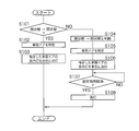
- FIG. 5 is a flowchart illustrating a procedure of processes executed by body ECU 100 in the first embodiment.
- the control unit 101 of the body ECU 100 acquires the detection signals output from the vehicle door opening / closing sensors 11 to 14 through the input unit 103, the control unit 101 executes the following processing.
- the control unit 101 first determines whether or not the acquired detection signal is a signal indicating a transition from the closed state to the open state of the vehicle doors D1 to D4 (step S101).
- the control unit 101 identifies the vehicle doors D1 to D4 that have transitioned from the closed state to the open state (step S102).
- the control unit 101 specifies that the vehicle door that has transitioned from the closed state to the open state is the vehicle door D1 (D2 to D4). can do.
- the control unit 101 outputs from the output unit 104 a control signal for lighting the interior lamps 21 (22 to 24) of the specified vehicle doors D1 (D2 to D4) in red, so that the interior lamps 21 (22 to 24) are output. ) In red (step S103).
- the control unit 101 is a signal indicating the transition from the open state to the closed state.
- the vehicle doors D1 to D4 that have transitioned from the open state to the closed state are identified (step S105).
- the control unit 101 specifies that the vehicle door that has transitioned from the open state to the closed state is the vehicle door D1 (D2 to D4). can do.
- control unit 101 outputs a control signal for turning on the interior lamps 21 (22 to 24) of the specified vehicle door D1 (D2 to D4) in blue from the output unit 104, whereby the interior lamps 21 (22 to 24) are output. ) Is lit blue (step S106).
- control unit 101 refers to the built-in timer and determines whether or not a set time (for example, 5 seconds) has elapsed since the control signal for lighting the interior lamp 21 (22 to 24) in blue is output ( Step S107).
- a set time for example, 5 seconds
- the control unit 101 waits until the set time elapses.
- control unit 101 When it is determined that the set time has elapsed (S107: YES), the control unit 101 outputs a control signal for turning off the interior lamps 21 (22 to 24) from the output unit 104, thereby causing the interior lamps 21 (22 to 24). ) Is turned off (step S108).
- the control unit 101 determines whether or not the signal indicates a transition from the closed state to the open state. Although it is configured, it may be configured to determine whether or not the signal indicates a transition from the open state to the closed state. In this case, when it is determined that the signal indicates a transition from the open state to the closed state, the above-described processing of steps S105 to S108 is performed, and it is determined that the signal is not a signal indicating the transition from the open state to the closed state. Then, it is determined that the acquired detection signal is a signal indicating a transition from the closed state to the open state, and the above-described processing of steps S102 to S103 is executed.
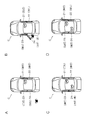
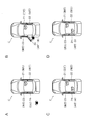
- FIG. 6 is an explanatory diagram for explaining an example of lighting when the vehicle door D4 is normally opened and closed in a state where the driver has already boarded.
- FIG. 6A shows a state where the driver has already boarded and all the vehicle doors D1 to D4 are normally closed. At this time, all the interior lights 21 to 24 are turned off.
- FIG. 6B shows a state in which the vehicle door D4 is opened in order for the occupant to sit on the left rear seat.
- the control unit 101 acquires a detection result indicating that the vehicle door D4 has transitioned from the closed state to the open state, and lights the interior lamp 24 in red.
- 6C and 6D show a state in which the vehicle door D4 is normally closed.
- the control unit 101 acquires a detection result indicating that the vehicle door D4 has transitioned from the open state to the closed state, turns on the interior lamp 24 in blue (FIG. 6C), and then turns off the light (FIG. 6D). .
- the driver can determine that the vehicle door D4 has been normally closed by confirming that the interior light 24 has changed from red to blue and then turned off.
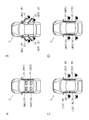
- FIG. 7 is an explanatory diagram illustrating an example of lighting when the vehicle door D4 is not normally closed.
- FIG. 7A shows a state where the driver has already boarded and all the vehicle doors D1 to D4 are normally closed. At this time, all the interior lights 21 to 24 are turned off.
- FIG. 7B shows a state in which the vehicle door D4 is opened in order for the occupant to sit on the left rear seat. The control unit 101 acquires a detection result indicating that the vehicle door D4 has transitioned from the closed state to the open state, and lights the interior lamp 24 in red.
- 7C and 7D show a state where the vehicle door D4 is not normally closed (half door state).
- the control unit 101 since the control unit 101 does not acquire a detection result indicating that the vehicle door D4 has transitioned from the open state to the closed state, the lighting color of the interior lamp 24 is not switched to blue, and the red lighting color is maintained. .
- the driver can determine that the vehicle door D4 has not been closed normally (that is, a half-door state) by confirming that the interior lamp 24 remains red.
- FIG. 8 is an explanatory diagram for explaining an example of lighting when the vehicle doors D1 to D4 are normally opened and closed when getting off.
- FIG. 8A shows a state in which an occupant is seated in each seat and all the vehicle doors D1 to D4 are normally closed. At this time, all the interior lights 21 to 24 are turned off.
- FIG. 8B shows a state in which the vehicle doors D1 to D4 are opened in order for each passenger to get off.
- the control unit 101 acquires a detection result indicating that the vehicle doors D1 to D4 have transitioned from the closed state to the open state, and lights the interior lights 21 to 24 in red.
- 8C and 8D show a state where the vehicle doors D1 to D4 are normally closed.
- the control unit 101 acquires a detection result indicating that the vehicle doors D1 to D4 have transitioned from the open state to the closed state, turns on the interior lights 21 to 24 in blue (FIG. 8C), and then turns off the lights. (FIG. 8D).
- the driver can determine that the vehicle doors D1 to D4 are normally closed by confirming that the interior lights 21 to 24 have changed from red to blue and then turned off.
- FIG. 9 is an explanatory diagram for explaining an example of lighting when the vehicle door D4 is not normally closed.
- FIG. 9A shows a state in which an occupant is seated in each seat and all the vehicle doors D1 to D4 are normally closed. At this time, all the interior lights 21 to 24 are turned off.
- FIG. 9B shows a state in which the vehicle doors D1 to D4 are opened in order for each passenger to get off.
- the control unit 101 acquires a detection result indicating that the vehicle doors D1 to D4 have transitioned from the closed state to the open state, and lights the interior lights 21 to 24 in red.
- 9C and 9D show a state where the vehicle door D4 is not normally closed (half door state).
- the control unit 101 acquires a detection result indicating that the vehicle doors D1 to D3 have transitioned from the open state to the closed state, turns on the interior lights 21 to 23 in blue (FIG. 9C), and then turns off the lights. (FIG. 9D).
- the control unit 101 since the control unit 101 does not acquire a detection result indicating that the vehicle door D4 has transitioned from the open state to the closed state, the lighting color of the interior lamp 24 is not switched to blue, and the red lighting color is maintained.
- the driver can determine that the vehicle door D4 has not been closed normally (that is, a half-door state) by confirming that the interior lamp 24 remains red.
- the interior lights 21 to 24 are provided at the lower end of the vehicle doors at the window openings of the vehicle doors D1 to D4, so that the passenger is seated in any seat in the vehicle. In addition, even when the passenger gets off the vehicle C, the lighting state of the interior lights 21 to 24 can be confirmed, and the open / closed state of the vehicle doors D1 to D4 can be grasped. Furthermore, since it is not necessary for the occupant to look up in order to confirm the lighting state of the interior lights 21 to 24, it is possible to reduce the situation that it is difficult to confirm because of overlapping with sunlight.
- the interior lights 21 to 24 are lit in red, and the vehicle doors D1 to D4 transition from the open state to the closed state.
- the lighting mode in which the interior lamps 21 to 24 are turned on in blue and then turned off has been described.
- the lighting mode is not limited to this.
- the interior lights 21 to 24 may be turned on using other lighting colors, and the brightness of the interior lights 21 to 24 and the timing of turning on and off according to the open / closed state of the vehicle doors D1 to D4. It is good also as a structure made to differ.
- the vehicle doors D1 to D4 are detected by distinguishing the open state, the closed state, and the half-door state, and when the half-door is detected, the interior lights 21 to 24 may be turned on with other light colors. Control to blink 21 to 24 may be performed.
- the lighting mode may be varied according to the detection result of the seating sensor 16. For example, when the vehicle C includes another display panel for notifying the open / closed state of the vehicle doors D1 to D4, and the driver can check the open / closed state of the vehicle doors D1 to D4 using the display panel, When the seating of the driver is detected by the seating sensor 16, the lighting control of the interior lights 21 to 24 may be omitted.
- Embodiment 2 demonstrates the application example in case the translucent member with low translucency, such as privacy glass, is used for the window glass of the vehicle C.
- FIG. 1 the translucent member with low translucency, such as privacy glass
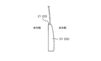
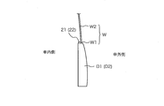
- FIG. 10 is an explanatory diagram for explaining an arrangement example of the interior lamp 21.
- FIG. 10 shows a partially enlarged view of the vehicle door D1 as viewed in the thickness direction.
- the interior lamp 21 is disposed at the lower end portion on the vehicle inner side of the window opening of the vehicle door D1.
- the window glass W that partitions the vehicle interior space and the vehicle exterior space at the window opening of the vehicle door D1 is positioned above the first light transmission region W1 and the second light transmission region provided at the lower end of the window opening. And a second light transmitting region W2.
- the second light transmitting region W2 is formed of a light transmitting member having a low light transmitting property
- the first light transmitting region W1 has a light transmitting property higher than that of the second light transmitting region W2. It is formed by.
- the interior lamp 21 is disposed so as to face the first light transmission region W1.
- the lighting state of the interior lamp 21 can be visually confirmed. Furthermore, even when the occupant gets off the vehicle C, the light emitted from the interior lamp 21 passes through the first light-transmitting region W1, so that it can be viewed from outside the vehicle.
Landscapes
- Engineering & Computer Science (AREA)
- Mechanical Engineering (AREA)
- Human Computer Interaction (AREA)
- Arrangements Of Lighting Devices For Vehicle Interiors, Mounting And Supporting Thereof, Circuits Therefore (AREA)
- Lighting Device Outwards From Vehicle And Optical Signal (AREA)
Priority Applications (2)
| Application Number | Priority Date | Filing Date | Title |
|---|---|---|---|
| CN201780037892.4A CN109415014A (zh) | 2016-07-05 | 2017-06-15 | 报知装置 |
| US16/314,810 US20190225144A1 (en) | 2016-07-05 | 2017-06-15 | Notification apparatus |
Applications Claiming Priority (2)
| Application Number | Priority Date | Filing Date | Title |
|---|---|---|---|
| JP2016-133559 | 2016-07-05 | ||
| JP2016133559A JP6638581B2 (ja) | 2016-07-05 | 2016-07-05 | 報知装置 |
Publications (1)
| Publication Number | Publication Date |
|---|---|
| WO2018008348A1 true WO2018008348A1 (ja) | 2018-01-11 |
Family
ID=60912124
Family Applications (1)
| Application Number | Title | Priority Date | Filing Date |
|---|---|---|---|
| PCT/JP2017/022062 Ceased WO2018008348A1 (ja) | 2016-07-05 | 2017-06-15 | 報知装置 |
Country Status (4)
| Country | Link |
|---|---|
| US (1) | US20190225144A1 (enExample) |
| JP (1) | JP6638581B2 (enExample) |
| CN (1) | CN109415014A (enExample) |
| WO (1) | WO2018008348A1 (enExample) |
Families Citing this family (8)
| Publication number | Priority date | Publication date | Assignee | Title |
|---|---|---|---|---|
| US10388085B2 (en) | 2017-07-14 | 2019-08-20 | Allstate Insurance Company | Distributed data processing system for processing remotely captured sensor data |
| US10820473B2 (en) * | 2017-11-20 | 2020-11-03 | Cnh Industrial America Llc | Work vehicle control system |
| JP6674484B2 (ja) * | 2018-01-18 | 2020-04-01 | 矢崎総業株式会社 | アシストグリップ用照明装置 |
| JP2019155969A (ja) * | 2018-03-07 | 2019-09-19 | 三菱自動車工業株式会社 | 車両用光報知機構 |
| JP7256104B2 (ja) * | 2019-10-23 | 2023-04-11 | 本田技研工業株式会社 | 車両制御装置、車両、車両制御装置の動作方法およびプログラム |
| JP7294219B2 (ja) * | 2020-04-06 | 2023-06-20 | トヨタ自動車株式会社 | 車両用ドア開閉制御システム及びドア開閉プログラム |
| JP2023056698A (ja) | 2021-10-08 | 2023-04-20 | マツダ株式会社 | 車両のドアハンドル制御装置 |
| JP7556375B2 (ja) * | 2022-04-20 | 2024-09-26 | トヨタ自動車株式会社 | 車室内照明装置 |
Citations (4)
| Publication number | Priority date | Publication date | Assignee | Title |
|---|---|---|---|---|
| JPH0581473U (ja) * | 1992-03-31 | 1993-11-05 | ナイルス部品株式会社 | ドアロックモニタ装置 |
| JP2002240625A (ja) * | 2001-02-20 | 2002-08-28 | Kyoichi Murata | 自動車用ドアバイザー |
| JP2004216990A (ja) * | 2003-01-10 | 2004-08-05 | Murakami Corp | 車輌用ドアノブ照明装置 |
| JP2015229414A (ja) * | 2014-06-05 | 2015-12-21 | アイシン精機株式会社 | 車両用開閉体照明装置 |
Family Cites Families (4)
| Publication number | Priority date | Publication date | Assignee | Title |
|---|---|---|---|---|
| US6536928B1 (en) * | 2000-03-03 | 2003-03-25 | Lear Corporation | Multi-colored vehicle interior lighting |
| JP2011105163A (ja) * | 2009-11-18 | 2011-06-02 | Faltec Co Ltd | 車両用照明装置 |
| US8547017B2 (en) * | 2011-05-13 | 2013-10-01 | Ford Global Technologies, Llc | Vehicle dome and reading light |
| US10363867B2 (en) * | 2013-11-21 | 2019-07-30 | Ford Global Technologies, Llc | Printed LED trim panel lamp |
-
2016
- 2016-07-05 JP JP2016133559A patent/JP6638581B2/ja active Active
-
2017
- 2017-06-15 US US16/314,810 patent/US20190225144A1/en not_active Abandoned
- 2017-06-15 CN CN201780037892.4A patent/CN109415014A/zh active Pending
- 2017-06-15 WO PCT/JP2017/022062 patent/WO2018008348A1/ja not_active Ceased
Patent Citations (4)
| Publication number | Priority date | Publication date | Assignee | Title |
|---|---|---|---|---|
| JPH0581473U (ja) * | 1992-03-31 | 1993-11-05 | ナイルス部品株式会社 | ドアロックモニタ装置 |
| JP2002240625A (ja) * | 2001-02-20 | 2002-08-28 | Kyoichi Murata | 自動車用ドアバイザー |
| JP2004216990A (ja) * | 2003-01-10 | 2004-08-05 | Murakami Corp | 車輌用ドアノブ照明装置 |
| JP2015229414A (ja) * | 2014-06-05 | 2015-12-21 | アイシン精機株式会社 | 車両用開閉体照明装置 |
Also Published As
| Publication number | Publication date |
|---|---|
| JP2018002027A (ja) | 2018-01-11 |
| US20190225144A1 (en) | 2019-07-25 |
| CN109415014A (zh) | 2019-03-01 |
| JP6638581B2 (ja) | 2020-01-29 |
Similar Documents
| Publication | Publication Date | Title |
|---|---|---|
| JP6638581B2 (ja) | 報知装置 | |
| US10160380B1 (en) | Enhanced informational vehicle puddle lamp assemblies | |
| JP6750523B2 (ja) | 車載装置 | |
| JP6444614B2 (ja) | 車両用室内灯装置 | |
| US9376055B2 (en) | Illuminated emblem | |
| US20170106836A1 (en) | Vehicle function control system using sensing and icon display module | |
| JP6078032B2 (ja) | 車載用警告装置 | |
| US10549718B2 (en) | Vehicle warning device | |
| JP5237894B2 (ja) | 車両用照明装置 | |
| US11014496B2 (en) | Lighting device for grab handle in vehicle | |
| JP2009126313A (ja) | 車両用モール | |
| US20150241015A1 (en) | Illuminated Emblem | |
| JP2005048578A (ja) | 自動車用ドアハンドルモジュール | |
| JP6411014B2 (ja) | 車輌ドア開報知照明装置 | |
| US20150239390A1 (en) | Illuminated Emblem | |
| JP2018058539A (ja) | 車室内照明装置 | |
| EP3048010B1 (en) | Vehicle interior illumination device | |
| JPH11105547A (ja) | 車室側ドアハンドル表示照明装置 | |
| CN113022436A (zh) | 基于氛围灯的预警提醒方法、预警提醒装置及车辆 | |
| JP2011042308A (ja) | 自動車用ウインドガラスの閉忘れ防止装置 | |
| EP3170705B1 (en) | Selective signalling method for a starter system of an engine of a vehicle | |
| KR101636168B1 (ko) | 자동차의 클러스터를 이용한 도어 열림 알림장치 및 그 방법 | |
| US20250346115A1 (en) | Vehicle switch device | |
| KR0126060Y1 (ko) | 자동차의 실내등 점등회로 | |
| JP2016135631A (ja) | 車内照明装置 |
Legal Events
| Date | Code | Title | Description |
|---|---|---|---|
| 121 | Ep: the epo has been informed by wipo that ep was designated in this application |
Ref document number: 17823955 Country of ref document: EP Kind code of ref document: A1 |
|
| NENP | Non-entry into the national phase |
Ref country code: DE |
|
| 122 | Ep: pct application non-entry in european phase |
Ref document number: 17823955 Country of ref document: EP Kind code of ref document: A1 |