WO2018008348A1 - 報知装置 - Google Patents
報知装置 Download PDFInfo
- Publication number
- WO2018008348A1 WO2018008348A1 PCT/JP2017/022062 JP2017022062W WO2018008348A1 WO 2018008348 A1 WO2018008348 A1 WO 2018008348A1 JP 2017022062 W JP2017022062 W JP 2017022062W WO 2018008348 A1 WO2018008348 A1 WO 2018008348A1
- Authority
- WO
- WIPO (PCT)
- Prior art keywords
- vehicle
- door
- state
- open
- closed state
- Prior art date
- Legal status (The legal status is an assumption and is not a legal conclusion. Google has not performed a legal analysis and makes no representation as to the accuracy of the status listed.)
- Ceased
Links
Images



Classifications
-
- B—PERFORMING OPERATIONS; TRANSPORTING
- B60—VEHICLES IN GENERAL
- B60Q—ARRANGEMENT OF SIGNALLING OR LIGHTING DEVICES, THE MOUNTING OR SUPPORTING THEREOF OR CIRCUITS THEREFOR, FOR VEHICLES IN GENERAL
- B60Q1/00—Arrangement of optical signalling or lighting devices, the mounting or supporting thereof or circuits therefor
- B60Q1/26—Arrangement of optical signalling or lighting devices, the mounting or supporting thereof or circuits therefor the devices being primarily intended to indicate the vehicle, or parts thereof, or to give signals, to other traffic
- B60Q1/32—Arrangement of optical signalling or lighting devices, the mounting or supporting thereof or circuits therefor the devices being primarily intended to indicate the vehicle, or parts thereof, or to give signals, to other traffic for indicating vehicle sides, e.g. clearance lights
- B60Q1/323—Arrangement of optical signalling or lighting devices, the mounting or supporting thereof or circuits therefor the devices being primarily intended to indicate the vehicle, or parts thereof, or to give signals, to other traffic for indicating vehicle sides, e.g. clearance lights on or for doors
- B60Q1/324—Arrangement of optical signalling or lighting devices, the mounting or supporting thereof or circuits therefor the devices being primarily intended to indicate the vehicle, or parts thereof, or to give signals, to other traffic for indicating vehicle sides, e.g. clearance lights on or for doors for signalling that a door is open or intended to be opened
-
- B—PERFORMING OPERATIONS; TRANSPORTING
- B60—VEHICLES IN GENERAL
- B60Q—ARRANGEMENT OF SIGNALLING OR LIGHTING DEVICES, THE MOUNTING OR SUPPORTING THEREOF OR CIRCUITS THEREFOR, FOR VEHICLES IN GENERAL
- B60Q1/00—Arrangement of optical signalling or lighting devices, the mounting or supporting thereof or circuits therefor
-
- B—PERFORMING OPERATIONS; TRANSPORTING
- B60—VEHICLES IN GENERAL
- B60Q—ARRANGEMENT OF SIGNALLING OR LIGHTING DEVICES, THE MOUNTING OR SUPPORTING THEREOF OR CIRCUITS THEREFOR, FOR VEHICLES IN GENERAL
- B60Q3/00—Arrangement of lighting devices for vehicle interiors; Lighting devices specially adapted for vehicle interiors
- B60Q3/50—Mounting arrangements
-
- B—PERFORMING OPERATIONS; TRANSPORTING
- B60—VEHICLES IN GENERAL
- B60Q—ARRANGEMENT OF SIGNALLING OR LIGHTING DEVICES, THE MOUNTING OR SUPPORTING THEREOF OR CIRCUITS THEREFOR, FOR VEHICLES IN GENERAL
- B60Q9/00—Arrangement or adaptation of signal devices not provided for in one of main groups B60Q1/00 - B60Q7/00, e.g. haptic signalling
-
- B—PERFORMING OPERATIONS; TRANSPORTING
- B60—VEHICLES IN GENERAL
- B60R—VEHICLES, VEHICLE FITTINGS, OR VEHICLE PARTS, NOT OTHERWISE PROVIDED FOR
- B60R25/00—Fittings or systems for preventing or indicating unauthorised use or theft of vehicles
- B60R25/30—Detection related to theft or to other events relevant to anti-theft systems
- B60R25/34—Detection related to theft or to other events relevant to anti-theft systems of conditions of vehicle components, e.g. of windows, door locks or gear selectors
-
- B—PERFORMING OPERATIONS; TRANSPORTING
- B60—VEHICLES IN GENERAL
- B60Q—ARRANGEMENT OF SIGNALLING OR LIGHTING DEVICES, THE MOUNTING OR SUPPORTING THEREOF OR CIRCUITS THEREFOR, FOR VEHICLES IN GENERAL
- B60Q3/00—Arrangement of lighting devices for vehicle interiors; Lighting devices specially adapted for vehicle interiors
- B60Q3/20—Arrangement of lighting devices for vehicle interiors; Lighting devices specially adapted for vehicle interiors for lighting specific fittings of passenger or driving compartments; mounted on specific fittings of passenger or driving compartments
- B60Q3/217—Doors, e.g. door sills; Steps
Definitions
- the present invention relates to a notification device.
- This application claims priority based on Japanese Patent Application No. 2016-133559 filed on July 5, 2016, and incorporates all the description content described in the above Japanese application.
- Patent Document 1 a light emitting diode is provided on the rear end surface of a saddle plate portion of an automobile door visor, and the light emitting diode is turned on to inform an occupant who gets off the automobile that the door is a half door, An automobile door visor for notifying a subsequent vehicle that the vehicle has opened is disclosed.
- the automobile door visor disclosed in Patent Document 1 is configured to notify an occupant outside the vehicle of the open / closed state of the vehicle door by turning on a light emitting diode provided on the rear end surface of the saddle plate portion. Since the light-emitting diode cannot be seen from the passengers in the vehicle, the passengers who have already boarded the vehicle have a problem that the open / closed state of the vehicle door cannot be confirmed. Also, passengers who get off from the driver's seat (the driver's seat and the rear seat of the driver's seat) cannot see the light emitting diodes provided on the door visor on the side opposite to the driver's seat (passenger seat). There is a problem that it is impossible to confirm the open / closed state of the vehicle door on the passenger seat side.
- This invention is made in view of such a situation, and it aims at providing the alerting
- a notification device is a notification device provided in a vehicle, and includes an interior lamp configured to allow a part of emitted light to pass through a window of the vehicle, and a door included in the vehicle.
- a detection unit that detects an open / closed state; and a control unit that controls lighting of the interior lamp in a lighting manner according to a detection result of the detection unit, and the open / closed state of the door by light emitted from the interior lamp To the inside and outside of the vehicle.
- the open / closed state of the vehicle door can be notified from both inside and outside the vehicle.
- FIG. 3 is a block diagram illustrating a configuration of a control system of the notification system according to Embodiment 1.
- FIG. 3 is a flowchart illustrating a procedure of processing executed by a body ECU in the first embodiment. It is explanatory drawing explaining the lighting example when a vehicle door opens and closes normally in the state where the driver has boarded. It is explanatory drawing explaining the lighting example when a vehicle door does not close normally.
- Embodiments of the present invention will be listed and described. Moreover, you may combine arbitrarily at least one part of embodiment described below.
- An alarm device is an alarm device provided in a vehicle, and an interior lamp configured to allow part of emitted light to pass through a window of the vehicle, and opening and closing of a door provided in the vehicle.
- a detection unit that detects a state, and a control unit that controls lighting of the interior lamp in a lighting manner according to a detection result of the detection unit, and the opening / closing state of the door is determined by light emitted from the interior lamp Notify inside and outside the car.
- the open / closed state of the door detected by the detection unit includes an open state in which the door is open and a closed state in which the door is closed
- the control unit includes the detection unit
- the lighting state of the interior lamp is made different between the open state and the closed state of the door detected by.
- the occupant can determine whether the door is open or closed by checking the lighting state of the interior lamp.
- the open / closed state of the door detected by the detection unit includes an open state in which the door is open, a closed state in which the door is completely closed, and an open state and the closed state.
- the control unit changes the lighting state of the interior lamp between the open state, the closed state, and the half door state of the door detected by the detection unit.
- the occupant can determine whether the door is open, closed, or half-door by checking the lighting state of the interior lamp. .
- the notification device is provided with the interior lamp corresponding to each of the plurality of doors provided in the vehicle, and the control unit is turned on according to a detection result relating to an open / closed state of each door. Then, lighting control of each interior lamp is performed.
- the open / closed state of each door can be determined by checking the lighting state of each interior light.
- the interior lamp is arranged so that the emitted light passes through a plurality of windows opposed in the vehicle width direction.
- the open / close state of the door provided on the opposite side of the exited door can be confirmed by the interior lamp.
- the interior lamp is disposed at a lower end portion on the vehicle interior side of a window opening provided in the door.
- the window has a first light-transmitting region provided at a lower end portion of the window, and has a light transmittance lower than that of the first light-transmitting region. And a second translucent area provided on the upper side of the translucent area.
- the interior lamp is arranged so as to face the first translucent area.
- the first light-transmitting region provided at the lower end portion of the light-transmitting member is provided.
- the light that passes through can inform the occupant who gets off the vehicle of the open / closed state of the door.
- the lighting mode includes lighting color, brightness, timing of turning on and off.
- the opening / closing state of the door can be notified to the occupant by changing the lighting mode according to the lighting color, brightness, lighting and extinguishing timing of the interior lamp.
- FIG. 1 is a schematic diagram illustrating a schematic configuration of a notification system according to the first embodiment.
- the notification system according to Embodiment 1 is a system for reporting the open / closed state of vehicle doors D1 to D4 provided in the vehicle C to both inside and outside the vehicle, and a body ECU (Electronic Control) provided inside the vehicle C Unit) 100 and interior lamps 21 to 24 controlled to be turned on by body ECU 100.
- body ECU Electronic Control
- the vehicle door D1 for the driver seat the vehicle door D2 for the right rear seat (driver seat rear seat), the vehicle door D3 for the passenger seat, and the left rear seat (rear seat of the passenger seat)
- the number of vehicle doors provided in the vehicle C is not limited to four.
- the body ECU 100 acquires the detection result from a detection unit (vehicle door opening / closing sensors 11 to 14 described later: see FIG. 4) that detects the opening / closing states of the vehicle doors D1 to D4, and responds to the opening / closing states of the vehicle doors D1 to D4.
- the lighting control of the interior lamps 21 to 24 is performed in the lighting mode.
- the interior lights 21 to 24 are, for example, light emitting devices including LEDs (Light Emitting Diodes), and are configured to be turned on and off by lighting control from the body ECU 100.
- the interior lamps 21 to 24 may be configured such that a plurality of LEDs are juxtaposed on a belt-like substrate that is long in one direction and emits light in a linear shape, and light emitted from the LEDs is diffused by a light guide plate. It may be configured to emit light in a strip shape. Further, the interior lamps 21 to 24 may be configured to emit light in a dot shape or an arbitrary shape using one or a plurality of LEDs.
- the interior lamps 21 to 24 are disposed, for example, at the lower end portion on the vehicle interior side of the window openings in the vehicle doors D1 to D4.
- 2 and 3 are explanatory views for explaining an arrangement example of the interior lamps 21 to 24.
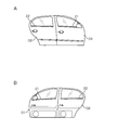
- FIG. 2A shows a front view of the vehicle doors D1 and D2 viewed from the outside of the vehicle
- FIG. 2B shows a rear view of the vehicle doors D1 and D2 viewed from the inside of the vehicle
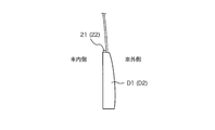
- FIG. 3 shows a partially enlarged view of the vehicle door D1 (D2) as viewed in the thickness direction.
- the interior lamps 21 and 22 are, for example, rod-shaped or strip-shaped light sources, and are arranged along the lower ends of the window openings provided in the vehicle doors D1 and D2, respectively. Therefore, when the interior lights 21 and 22 are lit, the occupant can visually recognize the lit state from outside the vehicle. Moreover, the interior lamp 21 (22) is arrange
- the interior lamps 21 and 22 are arranged as described above, the light emitted from the interior lamps 21 and 22 is transmitted through the windows of the vehicle doors D3 and D4 facing in the vehicle width direction. Even when the vehicle exits from the vehicle doors D3 and D4 on the side, the lighting state of the interior lights 21 and 22 can be visually confirmed.
- FIG. 4 is a block diagram illustrating the configuration of the control system of the notification system according to the first embodiment.
- the body ECU 100 includes a control unit 101, a storage unit 102, an input unit 103, an output unit 104, a communication unit 105, and the like.
- the control unit 101 includes, for example, a CPU (Central Processing Unit), a ROM (Read Only Memory), a RAM (Random Access Memory), and the like.
- the CPU in the control unit 101 controls the operation of the hardware included in the body ECU 100 by executing a control program stored in the ROM, and the interior of the vehicle in a lighting manner according to the open / closed state of the vehicle doors D1 to D4. A function for controlling lighting of the lamps 21 to 24 is realized.
- the RAM in the control unit 101 temporarily stores data generated during execution of the control program.
- the control unit 101 may have functions such as a timer that measures an elapsed time from when a measurement start instruction is given to when a measurement end instruction is given, and a counter that counts the number.
- the storage unit 102 is configured by a non-volatile memory such as an EEPROM (Electronically-Erasable-Programmable-Read-Only Memory), and stores information related to lighting control of the interior lights 21 to 24, for example.
- EEPROM Electrically-Erasable-Programmable-Read-Only Memory
- the input unit 103 includes interfaces for connecting the vehicle door opening / closing sensors 11 to 14, an ignition switch 15 (hereinafter referred to as IG switch 15), a seating sensor 16, and the like.
- IG switch 15 an ignition switch 15
- the input unit 103 acquires the detection result output from the vehicle door opening / closing sensors 11 to 14, the switch state output from the IG switch 15, the detection result output from the seating sensor 16, the acquired detection result Information is output to the control unit 101.
- Vehicle door open / close sensors 11 to 14 are sensors for detecting the open / closed state of the vehicle doors D1 to D4.
- the vehicle door open / close sensors 11 to 14 are provided corresponding to the vehicle doors D1 to D4, respectively, and individually detect the open / closed state of the vehicle doors D1 to D4 and output signals indicating the detection results.
- the vehicle door open / close sensors 11 to 14 may be switches that are turned on or off depending on whether the vehicle doors D1 to D4 are opened (open state) or closed (closed state), for example. It may be a sensor that detects the open state, the closed state, and the half door state between the open state and the closed state of the vehicle doors D1 to D4 by detecting the opening degree (opening degree) of D1 to D4. .
- the IG switch 15 is a push button type switch that starts a drive source (for example, an engine) of the vehicle C when the driver presses the button.
- the IG switch 15 is switched in a stepwise manner to an off position, an accessory position (ACC position), an on position, and an engine start position by an occupant pressing operation.
- a lamp control device such as a headlight, a locking mechanism for the vehicle doors D1 to D4, and the like can be operated.
- the ACC position an audio output device not shown in the figure.
- the display device and the like can be operated. In this way, only some in-vehicle devices with low power consumption can operate at the off position and the ACC position.
- many in-vehicle devices such as an air conditioner, a turn hazard, a wiper, and a meter device can operate. Further, the engine is started by igniting the spark plug at the engine start position, and returns to the on position after the engine is started.
- the seating sensor 16 is a sensor for detecting the seating state of the occupant.
- the seating sensor 16 is provided in a seat of each seat such as a driver seat, a passenger seat, and a rear seat provided in the vehicle C, for example, and the seating state of the occupant is determined for each seat based on the weight or pressure applied to the seat. Detect and output a signal indicating the detection result.
- the output unit 104 includes an interface for connecting the interior lights 21 to 24 and the like. When the output unit 104 acquires the control signal output from the control unit 101, the output unit 104 outputs the control signal to the interior lamps 21 to 24, thereby turning on or off the interior lamps 21 to 24.
- the interior lights 21 to 24 are light sources provided corresponding to the vehicle doors D1 to D4 as described above.
- the interior lights 21 to 24 are lighted in a lighting manner according to the open / closed state of the vehicle doors D1 to D4 by the lighting control from the control unit 101, and then get off the passengers seated in the vehicle and the vehicle C. The occupant is notified of the open / closed state of the vehicle doors D1 to D4.
- the communication unit 105 includes a CAN (Controller Area Network) communication interface, for example, and is connected to another ECU (not shown) via a communication network such as CAN.
- the communication unit 105 transmits / receives various data to / from other ECUs according to a protocol such as a CAN protocol.
- FIG. 5 is a flowchart illustrating a procedure of processes executed by body ECU 100 in the first embodiment.
- the control unit 101 of the body ECU 100 acquires the detection signals output from the vehicle door opening / closing sensors 11 to 14 through the input unit 103, the control unit 101 executes the following processing.
- the control unit 101 first determines whether or not the acquired detection signal is a signal indicating a transition from the closed state to the open state of the vehicle doors D1 to D4 (step S101).
- the control unit 101 identifies the vehicle doors D1 to D4 that have transitioned from the closed state to the open state (step S102).
- the control unit 101 specifies that the vehicle door that has transitioned from the closed state to the open state is the vehicle door D1 (D2 to D4). can do.
- the control unit 101 outputs from the output unit 104 a control signal for lighting the interior lamps 21 (22 to 24) of the specified vehicle doors D1 (D2 to D4) in red, so that the interior lamps 21 (22 to 24) are output. ) In red (step S103).
- the control unit 101 is a signal indicating the transition from the open state to the closed state.
- the vehicle doors D1 to D4 that have transitioned from the open state to the closed state are identified (step S105).
- the control unit 101 specifies that the vehicle door that has transitioned from the open state to the closed state is the vehicle door D1 (D2 to D4). can do.
- control unit 101 outputs a control signal for turning on the interior lamps 21 (22 to 24) of the specified vehicle door D1 (D2 to D4) in blue from the output unit 104, whereby the interior lamps 21 (22 to 24) are output. ) Is lit blue (step S106).
- control unit 101 refers to the built-in timer and determines whether or not a set time (for example, 5 seconds) has elapsed since the control signal for lighting the interior lamp 21 (22 to 24) in blue is output ( Step S107).
- a set time for example, 5 seconds
- the control unit 101 waits until the set time elapses.
- control unit 101 When it is determined that the set time has elapsed (S107: YES), the control unit 101 outputs a control signal for turning off the interior lamps 21 (22 to 24) from the output unit 104, thereby causing the interior lamps 21 (22 to 24). ) Is turned off (step S108).
- the control unit 101 determines whether or not the signal indicates a transition from the closed state to the open state. Although it is configured, it may be configured to determine whether or not the signal indicates a transition from the open state to the closed state. In this case, when it is determined that the signal indicates a transition from the open state to the closed state, the above-described processing of steps S105 to S108 is performed, and it is determined that the signal is not a signal indicating the transition from the open state to the closed state. Then, it is determined that the acquired detection signal is a signal indicating a transition from the closed state to the open state, and the above-described processing of steps S102 to S103 is executed.
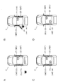
- FIG. 6 is an explanatory diagram for explaining an example of lighting when the vehicle door D4 is normally opened and closed in a state where the driver has already boarded.
- FIG. 6A shows a state where the driver has already boarded and all the vehicle doors D1 to D4 are normally closed. At this time, all the interior lights 21 to 24 are turned off.
- FIG. 6B shows a state in which the vehicle door D4 is opened in order for the occupant to sit on the left rear seat.
- the control unit 101 acquires a detection result indicating that the vehicle door D4 has transitioned from the closed state to the open state, and lights the interior lamp 24 in red.
- 6C and 6D show a state in which the vehicle door D4 is normally closed.
- the control unit 101 acquires a detection result indicating that the vehicle door D4 has transitioned from the open state to the closed state, turns on the interior lamp 24 in blue (FIG. 6C), and then turns off the light (FIG. 6D). .
- the driver can determine that the vehicle door D4 has been normally closed by confirming that the interior light 24 has changed from red to blue and then turned off.
- FIG. 7 is an explanatory diagram illustrating an example of lighting when the vehicle door D4 is not normally closed.
- FIG. 7A shows a state where the driver has already boarded and all the vehicle doors D1 to D4 are normally closed. At this time, all the interior lights 21 to 24 are turned off.
- FIG. 7B shows a state in which the vehicle door D4 is opened in order for the occupant to sit on the left rear seat. The control unit 101 acquires a detection result indicating that the vehicle door D4 has transitioned from the closed state to the open state, and lights the interior lamp 24 in red.
- 7C and 7D show a state where the vehicle door D4 is not normally closed (half door state).
- the control unit 101 since the control unit 101 does not acquire a detection result indicating that the vehicle door D4 has transitioned from the open state to the closed state, the lighting color of the interior lamp 24 is not switched to blue, and the red lighting color is maintained. .
- the driver can determine that the vehicle door D4 has not been closed normally (that is, a half-door state) by confirming that the interior lamp 24 remains red.
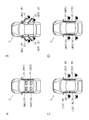
- FIG. 8 is an explanatory diagram for explaining an example of lighting when the vehicle doors D1 to D4 are normally opened and closed when getting off.
- FIG. 8A shows a state in which an occupant is seated in each seat and all the vehicle doors D1 to D4 are normally closed. At this time, all the interior lights 21 to 24 are turned off.
- FIG. 8B shows a state in which the vehicle doors D1 to D4 are opened in order for each passenger to get off.
- the control unit 101 acquires a detection result indicating that the vehicle doors D1 to D4 have transitioned from the closed state to the open state, and lights the interior lights 21 to 24 in red.
- 8C and 8D show a state where the vehicle doors D1 to D4 are normally closed.
- the control unit 101 acquires a detection result indicating that the vehicle doors D1 to D4 have transitioned from the open state to the closed state, turns on the interior lights 21 to 24 in blue (FIG. 8C), and then turns off the lights. (FIG. 8D).
- the driver can determine that the vehicle doors D1 to D4 are normally closed by confirming that the interior lights 21 to 24 have changed from red to blue and then turned off.
- FIG. 9 is an explanatory diagram for explaining an example of lighting when the vehicle door D4 is not normally closed.
- FIG. 9A shows a state in which an occupant is seated in each seat and all the vehicle doors D1 to D4 are normally closed. At this time, all the interior lights 21 to 24 are turned off.
- FIG. 9B shows a state in which the vehicle doors D1 to D4 are opened in order for each passenger to get off.
- the control unit 101 acquires a detection result indicating that the vehicle doors D1 to D4 have transitioned from the closed state to the open state, and lights the interior lights 21 to 24 in red.
- 9C and 9D show a state where the vehicle door D4 is not normally closed (half door state).
- the control unit 101 acquires a detection result indicating that the vehicle doors D1 to D3 have transitioned from the open state to the closed state, turns on the interior lights 21 to 23 in blue (FIG. 9C), and then turns off the lights. (FIG. 9D).
- the control unit 101 since the control unit 101 does not acquire a detection result indicating that the vehicle door D4 has transitioned from the open state to the closed state, the lighting color of the interior lamp 24 is not switched to blue, and the red lighting color is maintained.
- the driver can determine that the vehicle door D4 has not been closed normally (that is, a half-door state) by confirming that the interior lamp 24 remains red.
- the interior lights 21 to 24 are provided at the lower end of the vehicle doors at the window openings of the vehicle doors D1 to D4, so that the passenger is seated in any seat in the vehicle. In addition, even when the passenger gets off the vehicle C, the lighting state of the interior lights 21 to 24 can be confirmed, and the open / closed state of the vehicle doors D1 to D4 can be grasped. Furthermore, since it is not necessary for the occupant to look up in order to confirm the lighting state of the interior lights 21 to 24, it is possible to reduce the situation that it is difficult to confirm because of overlapping with sunlight.
- the interior lights 21 to 24 are lit in red, and the vehicle doors D1 to D4 transition from the open state to the closed state.
- the lighting mode in which the interior lamps 21 to 24 are turned on in blue and then turned off has been described.
- the lighting mode is not limited to this.
- the interior lights 21 to 24 may be turned on using other lighting colors, and the brightness of the interior lights 21 to 24 and the timing of turning on and off according to the open / closed state of the vehicle doors D1 to D4. It is good also as a structure made to differ.
- the vehicle doors D1 to D4 are detected by distinguishing the open state, the closed state, and the half-door state, and when the half-door is detected, the interior lights 21 to 24 may be turned on with other light colors. Control to blink 21 to 24 may be performed.
- the lighting mode may be varied according to the detection result of the seating sensor 16. For example, when the vehicle C includes another display panel for notifying the open / closed state of the vehicle doors D1 to D4, and the driver can check the open / closed state of the vehicle doors D1 to D4 using the display panel, When the seating of the driver is detected by the seating sensor 16, the lighting control of the interior lights 21 to 24 may be omitted.
- Embodiment 2 demonstrates the application example in case the translucent member with low translucency, such as privacy glass, is used for the window glass of the vehicle C.
- FIG. 1 the translucent member with low translucency, such as privacy glass
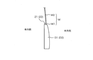
- FIG. 10 is an explanatory diagram for explaining an arrangement example of the interior lamp 21.
- FIG. 10 shows a partially enlarged view of the vehicle door D1 as viewed in the thickness direction.
- the interior lamp 21 is disposed at the lower end portion on the vehicle inner side of the window opening of the vehicle door D1.
- the window glass W that partitions the vehicle interior space and the vehicle exterior space at the window opening of the vehicle door D1 is positioned above the first light transmission region W1 and the second light transmission region provided at the lower end of the window opening. And a second light transmitting region W2.
- the second light transmitting region W2 is formed of a light transmitting member having a low light transmitting property
- the first light transmitting region W1 has a light transmitting property higher than that of the second light transmitting region W2. It is formed by.
- the interior lamp 21 is disposed so as to face the first light transmission region W1.
- the lighting state of the interior lamp 21 can be visually confirmed. Furthermore, even when the occupant gets off the vehicle C, the light emitted from the interior lamp 21 passes through the first light-transmitting region W1, so that it can be viewed from outside the vehicle.
Landscapes
- Engineering & Computer Science (AREA)
- Mechanical Engineering (AREA)
- Human Computer Interaction (AREA)
- Arrangements Of Lighting Devices For Vehicle Interiors, Mounting And Supporting Thereof, Circuits Therefore (AREA)
- Lighting Device Outwards From Vehicle And Optical Signal (AREA)
Abstract
車内及び車外の双方から車両ドアの開閉状態を報知することができる報知装置の提供。 車両に設けられた報知装置であって、出射光の一部が車両の窓を透過するように構成された車内灯と、車両が備えるドアの開閉状態を検知する検知部と、検知部の検知結果に応じた点灯態様にて、車内灯を点灯制御する制御部とを備え、車内灯からの出射光により、ドアの開閉状態を車内及び車外へ報知する。
Description
本発明は、報知装置に関する。
本出願は、2016年7月5日出願の日本出願第2016-133559号に基づく優先権を主張し、前記日本出願に記載された全ての記載内容を援用するものである。
本出願は、2016年7月5日出願の日本出願第2016-133559号に基づく優先権を主張し、前記日本出願に記載された全ての記載内容を援用するものである。
従来、車両が備えるドアの開閉状態を検知し、検知結果を報知するシステムが存在する。例えば、特許文献1には、自動車用ドアバイザーの庇板部の後端面に発光ダイオードを設け、当該発光ダイオードを点灯させることにより、自動車から降りた乗員に半ドアであることを知らせたり、ドアが開いたことを後続車に知らせたりする自動車用ドアバイザーが開示されている。
しかしながら、特許文献1に開示された自動車用ドアバイザーは、庇板部の後端面に設けた発光ダイオードを点灯することにより、車外の乗員に車両ドアの開閉状態を報知する構成としたものであり、車両内の乗員からは発光ダイオードを視認できないため、乗車済みの乗員は車両ドアの開閉状態を確認することができないという問題点を有している。また、運転席側の座席(運転席及び運転席の後部座席)から降車した乗員は、運転席とは反対側(助手席側)のドアバイザーに設けられた発光ダイオードを視認することができないため、助手席側の車両ドアの開閉状態を確認することができないという問題点を有している。
本発明は、斯かる事情に鑑みてなされたものであり、車内及び車外の双方から車両ドアの開閉状態を報知することができる報知装置を提供することを目的とする。
本発明の一態様に係る報知装置は、車両に設けられた報知装置であって、出射光の一部が前記車両の窓を透過するように構成された車内灯と、前記車両が備えるドアの開閉状態を検知する検知部と、該検知部の検知結果に応じた点灯態様にて、前記車内灯を点灯制御する制御部とを備え、前記車内灯からの出射光により、前記ドアの開閉状態を車内及び車外へ報知する。
本願によれば、車内及び車外の双方から車両ドアの開閉状態を報知することができる。
本発明の実施態様を列記して説明する。また、以下に記載する実施形態の少なくとも一部を任意に組み合わせてもよい。
本願の一態様に係る報知装置は、車両に設けられた報知装置であって、出射光の一部が前記車両の窓を透過するように構成された車内灯と、前記車両が備えるドアの開閉状態を検知する検知部と、該検知部の検知結果に応じた点灯態様にて、前記車内灯を点灯制御する制御部とを備え、前記車内灯からの出射光により、前記ドアの開閉状態を車内及び車外へ報知する。
上記一態様にあっては、乗員が車内で着座している場合、及び乗員が車両から降車した場合の双方において、車内灯の点灯状態を確認することにより、ドアの開閉状態を確認することができる。
本願の一態様に係る報知装置は、前記検知部が検知する前記ドアの開閉状態は、前記ドアが開いた開状態、及び前記ドアが閉じた閉状態を含み、前記制御部は、前記検知部により検知される前記ドアの開状態と閉状態との間で、前記車内灯の点灯態様を異ならせる。
上記一態様にあっては、乗員は車内灯の点灯状態を確認することで、ドアが開いた状態であるのか、閉じた状態であるのかを判別することができる。
本願の一態様に係る報知装置は、前記検知部が検知する前記ドアの開閉状態は、前記ドアが開いた開状態、前記ドアが完全に閉じた閉状態、及び前記開状態と前記閉状態との間の半ドア状態を含み、前記制御部は、前記検知部により検知される前記ドアの開状態、閉状態、及び半ドア状態の間で、前記車内灯の点灯態様を異ならせる。
上記一態様にあっては、乗員は車内灯の点灯状態を確認することで、ドアが開いた状態であるのか、閉じた状態であるのか、半ドアの状態であるのかを判別することができる。
本願の一態様に係る報知装置は、前記車両が備える複数のドアの夫々に対応させて前記車内灯を設けてあり、前記制御部は、各ドアの開閉状態に係る検知結果に応じた点灯態様にて、各車内灯を点灯制御する。
上記一態様にあっては、各ドアの開閉状態を各車内灯の点灯状態を確認することにより判別することができる。
本願の一態様に係る報知装置は、前記出射光が車幅方向に対向する複数の窓を透過するように前記車内灯を配置してある。
上記一態様にあっては、降車したドアの反対側に設けられているドアの開閉状態を車内灯により確認することができる。
本願の一態様に係る報知装置は、前記車内灯は前記ドアが備える窓開口部の車内側の下端部に配置してある。
上記一態様にあっては、乗員は車内灯を確認する際に見上げる必要がないので、視線方向が太陽光と重なる可能性が低くなり、車内灯を良好に確認することが可能となる。
本願の一態様に係る報知装置は、前記窓は、該窓の下端部に設けた第1の透光領域と、該第1の透光領域より低い光透過性を有し、前記第1の透光領域の上側に設けた第2の透光領域とを備えた透光性部材により構成されており、前記車内灯を前記第1の透光領域に対向するように配置してある。
上記一態様にあっては、プライバシーガラスのような透光性が低い透光性部材が用いられている場合であっても、透光性部材の下端部に設けた第1の透光領域を透過する光により、降車した乗員にドアの開閉状態を報知することができる。
本願の一態様に係る報知装置は、前記点灯態様は、点灯色、明るさ、点灯及び消灯のタイミングを含む。
上記一態様にあっては、車内灯の点灯色、明るさ、点灯及び消灯のタイミングにより点灯態様を異ならせることにより、ドアの開閉状態を乗員に報知することができる。
以下、本発明をその実施の形態を示す図面に基づいて具体的に説明する。
(実施の形態1)
図1は実施の形態1に係る報知システムの概略構成を説明する模式図である。実施の形態1に係る報知システムは、車両Cが備える車両ドアD1~D4の開閉状態を車内及び車外の双方へ報知するためのシステムであり、車両Cの内部に設けられたボディECU(Electronic Control Unit)100と、ボディECU100により点灯制御される車内灯21~24とを備える。
(実施の形態1)
図1は実施の形態1に係る報知システムの概略構成を説明する模式図である。実施の形態1に係る報知システムは、車両Cが備える車両ドアD1~D4の開閉状態を車内及び車外の双方へ報知するためのシステムであり、車両Cの内部に設けられたボディECU(Electronic Control Unit)100と、ボディECU100により点灯制御される車内灯21~24とを備える。
なお、本実施の形態では、運転席用の車両ドアD1、右後部座席(運転席の後部座席)用の車両ドアD2、助手席用の車両ドアD3、及び左後部座席(助手席の後部座席)用の車両ドアD4の4つを車両Cが備えた構成について説明を行うが、車両Cが備える車両ドアの数は4つに限定されるものではない。
ボディECU100は、車両ドアD1~D4の開閉状態を検知する検知部(後述する車両ドア開閉センサ11~14:図4を参照)から検知結果を取得し、車両ドアD1~D4の開閉状態に応じた点灯態様にて、車内灯21~24の点灯制御を行う。
車内灯21~24は、例えばLED(Light Emitting Diode)を備えた発光装置であり、ボディECU100からの点灯制御により点灯及び消灯するように構成されている。なお、車内灯21~24は、一方向に長い帯状の基板に複数のLEDを並置して線状に光を発するように構成してもよく、LEDから出射される光を導光板により拡散して帯状に光を発するように構成してもよい。また、車内灯21~24は、1又は複数のLEDを用いて点状又は任意形状で光を発するように構成してもよい。
車内灯21~24は、例えば、各車両ドアD1~D4における窓開口部の車内側の下端部に配置される。図2及び図3は車内灯21~24の配置例を説明する説明図である。図2Aは車外から眺めた車両ドアD1,D2の正面図を示し、図2Bは車内から眺めた車両ドアD1,D2の背面図を示している。また、図3は車両ドアD1(D2)を厚み方向に眺めた部分拡大図を示している。
図2Aに示されているように、車内灯21,22は、例えば棒状又は帯状の光源であり、それぞれ車両ドアD1,D2が備える窓開口部の下端に沿って配置されている。よって、車内灯21,22が点灯した場合、乗員は車外から点灯状態を視認することが可能である。また、車内灯21(22)は、図3に示されているように、車両ドアD1(D2)の窓開口部の車内側の下端部に配置されている。よって、乗員は車内に着座している場合であっても、車内灯21(22)の点灯状態を視認することができる。更に、上記のように車内灯21,22を配置することにより、車内灯21,22から発せられる光は、車幅方向に対向する車両ドアD3,D4の窓を透過するので、乗員が助手席側の車両ドアD3,D4から降車した場合であっても、車内灯21,22の点灯状態を視認することが可能となる。
なお、図2及び図3では、車両Cの右側面に配置される車内灯21,22について説明したが、車両Cの左側面に配置される車内灯23,24についても同様である。
図4は実施の形態1に係る報知システムの制御系の構成を説明するブロック図である。ボディECU100は、制御部101、記憶部102、入力部103、出力部104、通信部105などを備える。
制御部101は、例えば、CPU(Central Processing Unit)、ROM(Read Only Memory)、RAM(Random Access Memory)などを備える。制御部101内のCPUは、ROMに格納された制御プログラムを実行することにより、ボディECU100が備える上記ハードウェアの動作を制御し、車両ドアD1~D4の開閉状態に応じた点灯態様にて車内灯21~24を点灯制御する機能等を実現する。制御部101内のRAMには、制御プログラムの実行中に生成されるデータ等が一時的に記憶される。なお、制御部101は、計測開始指示を与えてから計測終了指示を与えるまでの経過時間を計測するタイマ、数をカウントするカウンタ等の機能を備えていてもよい。
記憶部102は、例えば、EEPROM(Electronically Erasable Programmable Read Only Memory)などの不揮発性メモリにより構成されており、例えば車内灯21~24の点灯制御に関する情報等を記憶する。
入力部103は、車両ドア開閉センサ11~14、イグニッションスイッチ15(以下、IGスイッチ15と記載)、着座センサ16などを接続するためのインタフェースを備える。入力部103は、車両ドア開閉センサ11~14から出力される検知結果、IGスイッチ15から出力されるスイッチ状態、着座センサ16から出力される検知結果等を取得した場合、取得した検知結果等の情報を制御部101へ出力する。
車両ドア開閉センサ11~14は、車両ドアD1~D4の開閉状態を検知するためのセンサである。車両ドア開閉センサ11~14は、それぞれ車両ドアD1~D4に対応して設けられており、車両ドアD1~D4の開閉状態を個別に検知し、検知結果を示す信号を出力する。なお、車両ドア開閉センサ11~14は、例えば車両ドアD1~D4が開いた状態(開状態)か閉じた状態(閉状態)かに応じてオン又はオフするスイッチであってもよく、車両ドアD1~D4の開き具合(開度)を検出することにより、車両ドアD1~D4の開状態、閉状態、及び開状態と閉状態との間の半ドア状態を検知するセンサであってもよい。
IGスイッチ15は、運転者がボタンを押下することによって車両Cの駆動源(例えばエンジン)を始動させる押しボタン式のスイッチ等である。IGスイッチ15は、乗員の押下操作によって、オフ位置、アクセサリ位置(ACC位置)、オン位置、及びエンジン始動位置に段階的に切り替えられる。
一般的にIGスイッチ15がオフ位置にある場合には、ヘッドライト等のランプ制御装置、車両ドアD1~D4の施錠機構等が動作可能であり、ACC位置では、図に示していない音声出力装置、表示装置等が動作可能となる。このように、オフ位置及びACC位置では電力消費量が小さい一部の車載機器のみが動作可能である。一方、IGスイッチ15がオン位置にある場合には、空気調和装置、ターンハザード、ワイパー、メータ機器等の多くの車載機器が動作可能となる。さらにエンジン始動位置では点火プラグに点火してエンジンが始動し、エンジン始動後はオン位置に戻るように構成されている。
着座センサ16は、乗員の着座状態を検知するためのセンサである。着座センサ16は、例えば車両Cが備える運転席、助手席、後部座席などの各座席のシート内に設けられており、シートに加わる重量又は圧力等に基づいて、乗員の着座状態を座席毎に検知し、検知結果を示す信号を出力する。
出力部104は、車内灯21~24などを接続するためのインタフェースを備える。出力部104は、制御部101から出力される制御信号を取得した場合、当該制御信号を車内灯21~24へ出力することにより、車内灯21~24を点灯又は消灯させる。
車内灯21~24は、前述したように、車両ドアD1~D4に対応して設けられた光源である。車内灯21~24は、制御部101からの点灯制御により、車両ドアD1~D4の開閉状態に応じた点灯態様にて点灯することにより、車内に着座している乗員、及び車両Cから降車した乗員に対して、車両ドアD1~D4の開閉状態を報知する。
通信部105は、例えばCAN(Controller Area Network)通信インタフェースを備えており、CANなどの通信ネットワークを介して他のECU(不図示)に接続されている。通信部105は、CANプロトコルなどのプロトコルに従って他のECUと各種データの送受信を行う。
以下、実施の形態1に係る報知システムの動作について説明する。
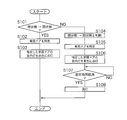
図5は実施の形態1におけるボディECU100が実行する処理の手順を説明するフローチャートである。ボディECU100の制御部101は、車両ドア開閉センサ11~14から出力される検知信号を入力部103を通じて取得した場合、以下の処理を実行する。
図5は実施の形態1におけるボディECU100が実行する処理の手順を説明するフローチャートである。ボディECU100の制御部101は、車両ドア開閉センサ11~14から出力される検知信号を入力部103を通じて取得した場合、以下の処理を実行する。
制御部101は、まず、取得した検知信号が車両ドアD1~D4の閉状態から開状態への遷移を示す信号であるか否かを判断する(ステップS101)。
閉状態から開状態の遷移を示す信号であると判断した場合(S101:YES)、制御部101は、閉状態から開状態に遷移した車両ドアD1~D4を特定する(ステップS102)。取得した検知信号の出力元が車両ドア開閉センサ11(12~14)である場合、制御部101は、閉状態から開状態に遷移した車両ドアが車両ドアD1(D2~D4)であると特定することができる。次いで、制御部101は、特定した車両ドアD1(D2~D4)の車内灯21(22~24)を赤色に点灯させる制御信号を出力部104から出力することにより、車内灯21(22~24)を赤色に点灯させる(ステップS103)。
一方、取得した検知信号が閉状態から開状態の遷移を示す信号でないと判断した場合(S101:NO)、制御部101は、取得した検知信号が開状態から閉状態の遷移を示す信号であると判断し(ステップS104)、開状態から閉状態に遷移した車両ドアD1~D4を特定する(ステップS105)。取得した検知信号の出力元が車両ドア開閉センサ11(12~14)である場合、制御部101は、開状態から閉状態に遷移した車両ドアが車両ドアD1(D2~D4)であると特定することができる。次いで、制御部101は、特定した車両ドアD1(D2~D4)の車内灯21(22~24)を青色に点灯させる制御信号を出力部104から出力することにより、車内灯21(22~24)を青に点灯させる(ステップS106)。
次いで、制御部101は、内蔵タイマを参照し、車内灯21(22~24)を青色に点灯させる制御信号を出力してから設定時間(例えば5秒)が経過したか否かを判断する(ステップS107)。設定時間が経過していない場合(S107:NO)、制御部101は、設定時間が経過するまで待機する。
設定時間が経過したと判断した場合(S107:YES)、制御部101は、車内灯21(22~24)を消灯させる制御信号を出力部104から出力することにより、車内灯21(22~24)を消灯させる(ステップS108)。
以上のように、本実施の形態では、車両ドアD1~D4毎に開閉状態を検知し、その検知結果に応じて、車内灯21~24の点灯態様を異ならせて点灯させることができる。
なお、本実施の形態では、車両ドア開閉センサ11~14から出力される検知信号を取得した場合、制御部101は、閉状態から開状態への遷移を示す信号であるか否かを判断する構成としたが、開状態から閉状態への遷移を示す信号であるか否かを判断する構成としてもよい。この場合、開状態から閉状態への遷移を示す信号であると判断したときに、上述したステップS105~S108の処理を実行し、開状態から閉状態への遷移を示す信号でないと判断したとき、取得した検知信号が閉状態から開状態への遷移を示す信号であると判断し、上述したステップS102~S103の処理を実行する。
以下、車内灯21~24の点灯例を説明する。
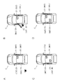
図6は運転者が乗車済みの状態にて車両ドアD4が正常に開閉した場合の点灯例を説明する説明図である。図6Aは、運転者が既に乗車済みであり、全ての車両ドアD1~D4が正常に閉じた状態を示している。このとき、車内灯21~24はすべて消灯した状態となる。図6Bは、乗員が左後部座席に着座するために、車両ドアD4を開けた状態を示している。制御部101は、車両ドアD4が閉状態から開状態に遷移したことを示す検知結果を取得して、車内灯24を赤色に点灯させる。図6C及び6Dは、車両ドアD4が正常に閉じた状態を示している。このとき、制御部101は、車両ドアD4が開状態から閉状態に遷移したことを示す検知結果を取得して、車内灯24を青色に点灯させ(図6C)、その後消灯させる(図6D)。運転者は、車内灯24が赤色から青色に灯色が変化し、その後消灯したことを確認することにより、車両ドアD4が正常に閉じたと判断することができる。
図6は運転者が乗車済みの状態にて車両ドアD4が正常に開閉した場合の点灯例を説明する説明図である。図6Aは、運転者が既に乗車済みであり、全ての車両ドアD1~D4が正常に閉じた状態を示している。このとき、車内灯21~24はすべて消灯した状態となる。図6Bは、乗員が左後部座席に着座するために、車両ドアD4を開けた状態を示している。制御部101は、車両ドアD4が閉状態から開状態に遷移したことを示す検知結果を取得して、車内灯24を赤色に点灯させる。図6C及び6Dは、車両ドアD4が正常に閉じた状態を示している。このとき、制御部101は、車両ドアD4が開状態から閉状態に遷移したことを示す検知結果を取得して、車内灯24を青色に点灯させ(図6C)、その後消灯させる(図6D)。運転者は、車内灯24が赤色から青色に灯色が変化し、その後消灯したことを確認することにより、車両ドアD4が正常に閉じたと判断することができる。
図7は車両ドアD4が正常に閉じなかった場合の点灯例を説明する説明図である。図7Aは、運転者が既に乗車済みであり、全ての車両ドアD1~D4が正常に閉じた状態を示している。このとき、車内灯21~24はすべて消灯した状態となる。図7Bは、乗員が左後部座席に着座するために、車両ドアD4を開けた状態を示している。制御部101は、車両ドアD4が閉状態から開状態に遷移したことを示す検知結果を取得して、車内灯24を赤色に点灯させる。図7C及び図7Dは、車両ドアD4が正常に閉じなかった状態(半ドアの状態)を示している。このとき、制御部101は、車両ドアD4が開状態から閉状態に遷移したことを示す検知結果を取得しないので、車内灯24の点灯色は青色に切り替わらず、赤色の点灯色が維持される。運転者は、車内灯24が赤色のままであることを確認することにより、車両ドアD4が正常に閉じなかった(すなわち、半ドアの状態である)と判断することができる。
図8は降車時に車両ドアD1~D4が正常に開閉した場合の点灯例を説明する説明図である。図8Aは、各座席に乗員が着座し、全ての車両ドアD1~D4が正常に閉じた状態を示している。このとき、車内灯21~24はすべて消灯した状態となる。図8Bは、各乗員が降車するために、車両ドアD1~D4を開けた状態を示している。制御部101は、車両ドアD1~D4が閉状態から開状態に遷移したことを示す検知結果を取得して、車内灯21~24を赤色に点灯させる。図8C及び8Dは、車両ドアD1~D4が正常に閉じた状態を示している。このとき、制御部101は、車両ドアD1~D4が開状態から閉状態に遷移したことを示す検知結果を取得して、車内灯21~24を青色に点灯させ(図8C)、その後消灯させる(図8D)。運転者は、車内灯21~24が赤色から青色に灯色が変化し、その後消灯したことを確認することにより、車両ドアD1~D4が正常に閉じたと判断することができる。
図9は車両ドアD4が正常に閉じなかった場合の点灯例を説明する説明図である。図9Aは、各座席に乗員が着座し、全ての車両ドアD1~D4が正常に閉じた状態を示している。このとき、車内灯21~24はすべて消灯した状態となる。図9Bは、各乗員が降車するために、車両ドアD1~D4を開けた状態を示している。制御部101は、車両ドアD1~D4が閉状態から開状態に遷移したことを示す検知結果を取得して、車内灯21~24を赤色に点灯させる。図9C及び図9Dは、車両ドアD4が正常に閉じなかった状態(半ドアの状態)を示している。このとき、制御部101は、車両ドアD1~D3が開状態から閉状態に遷移したことを示す検知結果を取得して、車内灯21~23を青色に点灯させ(図9C)、その後消灯させる(図9D)。一方、制御部101は、車両ドアD4が開状態から閉状態に遷移したことを示す検知結果を取得しないので、車内灯24の点灯色は青色に切り替わらず、赤色の点灯色が維持される。運転者は、車内灯24が赤色のままであることを確認することにより、車両ドアD4が正常に閉じなかった(すなわち、半ドアの状態である)と判断することができる。
本実施の形態では、車内灯21~24を各車両ドアD1~D4の窓開口部における車内側の下端部に設けているため、乗員が車両内のどの座席に着座している場合であっても、また乗員が車両Cから降車した場合であっても、車内灯21~24の点灯状態を確認することができ、車両ドアD1~D4の開閉状態を把握することができる。更に、乗員は、車内灯21~24の点灯状態を確認するために見上げる必要がないため、太陽光と重なって確認しづらいという状況を少なくすることができる。
なお、本実施の形態では、車両ドアD1~D4が閉状態から開状態に遷移した場合に、車内灯21~24を赤色に点灯させ、車両ドアD1~D4が開状態から閉状態に遷移した場合に、車内灯21~24を青色に点灯させ、その後消灯させる点灯態様について説明したが、点灯態様はこの限りではない。例えば、他の点灯色を用いて車内灯21~24を点灯させる構成であってもよく、車内灯21~24の明るさ、点灯及び消灯のタイミングを車両ドアD1~D4の開閉状態に応じて異ならせる構成としてもよい。
また、車両ドアD1~D4の開状態、閉状態、及び半ドア状態を区別して検知し、半ドアを検知した場合、他の灯色で車内灯21~24を点灯させてもよく、車内灯21~24を点滅させる制御を行ってもよい。
更に、着座センサ16の検知結果に応じて点灯態様を異ならせてもよい。例えば、車両Cが車両ドアD1~D4の開閉状態を報知するための他の表示パネルを備えており、運転者がその表示パネルにより車両ドアD1~D4の開閉状態を確認することができる場合、運転者の着座を着座センサ16により検知したとき、車内灯21~24の点灯制御を省略してもよい。
(実施の形態2)
実施の形態2では、車両Cの窓ガラスにプライバシーガラスなどの透光性が低い透光性部材が用いられている場合の適用例について説明する。
実施の形態2では、車両Cの窓ガラスにプライバシーガラスなどの透光性が低い透光性部材が用いられている場合の適用例について説明する。
図10は車内灯21の配置例を説明する説明図である。図10は車両ドアD1を厚み方向に眺めた部分拡大図を示している。車内灯21は、実施の形態1と同様に、車両ドアD1の窓開口部の車内側の下端部に配置される。一方、車両ドアD1の窓開口部にて車内空間と車外空間とを仕切る窓ガラスWは、窓開口部の下端部に設けた第1透光領域W1と、第2透光領域の上側に位置する第2透光領域W2とを有する。ここで、第2透光領域W2は、透光性が低い透光性部材により形成されており、第1透光領域W1は、第2透光領域W2より透光性が高い透光性部材により形成されている。なお、車内灯21は、第1透光領域W1に対向させて配置されている。
よって、乗員は車内に着座している場合、車内灯21の点灯状態を視認することができる。更に、乗員が車両Cから降車した場合であっても、車内灯21から発せられる光は第1透光領域W1を透過するので、車外から視認することが可能となる。
なお、図10では、車内灯21について説明したが、車内灯22~24及び車両ドアD2~D4が備える窓ガラスについても同様である。
今回開示された実施の形態は、全ての点で例示であって、制限的なものではないと考えられるべきである。本発明の範囲は、上述した意味ではなく、請求の範囲によって示され、請求の範囲と均等の意味及び範囲内での全ての変更が含まれることが意図される。
C 車両
D1~D4 車両ドア
11~14 車両ドア開閉センサ
15 IGスイッチ
16 着座センサ
21~24 車内灯
100 ボディECU
101 制御部
102 記憶部
103 入力部
104 出力部
105 通信部
D1~D4 車両ドア
11~14 車両ドア開閉センサ
15 IGスイッチ
16 着座センサ
21~24 車内灯
100 ボディECU
101 制御部
102 記憶部
103 入力部
104 出力部
105 通信部
Claims (8)
- 車両に設けられた報知装置であって、
出射光の一部が前記車両の窓を透過するように構成された車内灯と、
前記車両が備えるドアの開閉状態を検知する検知部と、
該検知部の検知結果に応じた点灯態様にて、前記車内灯を点灯制御する制御部と
を備え、
前記車内灯からの出射光により、前記ドアの開閉状態を車内及び車外へ報知する
報知装置。 - 前記検知部が検知する前記ドアの開閉状態は、前記ドアが開いた開状態、及び前記ドアが閉じた閉状態を含み、
前記制御部は、前記検知部により検知される前記ドアの開状態と閉状態との間で、前記車内灯の点灯態様を異ならせる
請求項1に記載の報知装置。 - 前記検知部が検知する前記ドアの開閉状態は、前記ドアが開いた開状態、前記ドアが完全に閉じた閉状態、及び前記開状態と前記閉状態との間の半ドア状態を含み、
前記制御部は、前記検知部により検知される前記ドアの開状態、閉状態、及び半ドア状態の間で、前記車内灯の点灯態様を異ならせる
請求項1に記載の報知装置。 - 前記車両が備える複数のドアの夫々に対応させて前記車内灯を設けてあり、
前記制御部は、各ドアの開閉状態に係る検知結果に応じた点灯態様にて、各車内灯を点灯制御する
請求項1から請求項3の何れか1つに記載の報知装置。 - 前記出射光が車幅方向に対向する複数の窓を透過するように前記車内灯を配置してある
請求項1から請求項4の何れか1つに記載の報知装置。 - 前記車内灯は前記ドアが備える窓開口部の車内側の下端部に配置してある
請求項1から請求項5の何れか1つに記載の報知装置。 - 前記窓は、該窓の下端部に設けた第1の透光領域と、該第1の透光領域より低い光透過性を有し、前記第1の透光領域の上側に設けた第2の透光領域とを備えた透光性部材により構成されており、
前記車内灯を前記第1の透光領域に対向するように配置してある
請求項1から請求項6の何れか1つに記載の報知装置。 - 前記点灯態様は、点灯色、明るさ、点灯及び消灯のタイミングを含む
請求項1から請求項7の何れか1つに記載の報知装置。
Priority Applications (2)
| Application Number | Priority Date | Filing Date | Title |
|---|---|---|---|
| CN201780037892.4A CN109415014A (zh) | 2016-07-05 | 2017-06-15 | 报知装置 |
| US16/314,810 US20190225144A1 (en) | 2016-07-05 | 2017-06-15 | Notification apparatus |
Applications Claiming Priority (2)
| Application Number | Priority Date | Filing Date | Title |
|---|---|---|---|
| JP2016-133559 | 2016-07-05 | ||
| JP2016133559A JP6638581B2 (ja) | 2016-07-05 | 2016-07-05 | 報知装置 |
Publications (1)
| Publication Number | Publication Date |
|---|---|
| WO2018008348A1 true WO2018008348A1 (ja) | 2018-01-11 |
Family
ID=60912124
Family Applications (1)
| Application Number | Title | Priority Date | Filing Date |
|---|---|---|---|
| PCT/JP2017/022062 Ceased WO2018008348A1 (ja) | 2016-07-05 | 2017-06-15 | 報知装置 |
Country Status (4)
| Country | Link |
|---|---|
| US (1) | US20190225144A1 (ja) |
| JP (1) | JP6638581B2 (ja) |
| CN (1) | CN109415014A (ja) |
| WO (1) | WO2018008348A1 (ja) |
Families Citing this family (9)
| Publication number | Priority date | Publication date | Assignee | Title |
|---|---|---|---|---|
| US10976173B2 (en) | 2017-07-14 | 2021-04-13 | Allstate Insurance Company | Distributed data processing systems for processing remotely captured sensor data |
| US10820473B2 (en) * | 2017-11-20 | 2020-11-03 | Cnh Industrial America Llc | Work vehicle control system |
| JP6674484B2 (ja) * | 2018-01-18 | 2020-04-01 | 矢崎総業株式会社 | アシストグリップ用照明装置 |
| JP2019155969A (ja) * | 2018-03-07 | 2019-09-19 | 三菱自動車工業株式会社 | 車両用光報知機構 |
| JP7256104B2 (ja) * | 2019-10-23 | 2023-04-11 | 本田技研工業株式会社 | 車両制御装置、車両、車両制御装置の動作方法およびプログラム |
| JP7294219B2 (ja) * | 2020-04-06 | 2023-06-20 | トヨタ自動車株式会社 | 車両用ドア開閉制御システム及びドア開閉プログラム |
| JP7825126B2 (ja) | 2021-10-08 | 2026-03-06 | マツダ株式会社 | 車両のドアハンドル制御装置 |
| JP7741763B2 (ja) * | 2022-04-20 | 2025-09-18 | トヨタ自動車株式会社 | 車室内照明装置 |
| JP7556375B2 (ja) * | 2022-04-20 | 2024-09-26 | トヨタ自動車株式会社 | 車室内照明装置 |
Citations (4)
| Publication number | Priority date | Publication date | Assignee | Title |
|---|---|---|---|---|
| JPH0581473U (ja) * | 1992-03-31 | 1993-11-05 | ナイルス部品株式会社 | ドアロックモニタ装置 |
| JP2002240625A (ja) * | 2001-02-20 | 2002-08-28 | Kyoichi Murata | 自動車用ドアバイザー |
| JP2004216990A (ja) * | 2003-01-10 | 2004-08-05 | Murakami Corp | 車輌用ドアノブ照明装置 |
| JP2015229414A (ja) * | 2014-06-05 | 2015-12-21 | アイシン精機株式会社 | 車両用開閉体照明装置 |
Family Cites Families (4)
| Publication number | Priority date | Publication date | Assignee | Title |
|---|---|---|---|---|
| US6536928B1 (en) * | 2000-03-03 | 2003-03-25 | Lear Corporation | Multi-colored vehicle interior lighting |
| JP2011105163A (ja) * | 2009-11-18 | 2011-06-02 | Faltec Co Ltd | 車両用照明装置 |
| US8547017B2 (en) * | 2011-05-13 | 2013-10-01 | Ford Global Technologies, Llc | Vehicle dome and reading light |
| US10363867B2 (en) * | 2013-11-21 | 2019-07-30 | Ford Global Technologies, Llc | Printed LED trim panel lamp |
-
2016
- 2016-07-05 JP JP2016133559A patent/JP6638581B2/ja active Active
-
2017
- 2017-06-15 WO PCT/JP2017/022062 patent/WO2018008348A1/ja not_active Ceased
- 2017-06-15 US US16/314,810 patent/US20190225144A1/en not_active Abandoned
- 2017-06-15 CN CN201780037892.4A patent/CN109415014A/zh active Pending
Patent Citations (4)
| Publication number | Priority date | Publication date | Assignee | Title |
|---|---|---|---|---|
| JPH0581473U (ja) * | 1992-03-31 | 1993-11-05 | ナイルス部品株式会社 | ドアロックモニタ装置 |
| JP2002240625A (ja) * | 2001-02-20 | 2002-08-28 | Kyoichi Murata | 自動車用ドアバイザー |
| JP2004216990A (ja) * | 2003-01-10 | 2004-08-05 | Murakami Corp | 車輌用ドアノブ照明装置 |
| JP2015229414A (ja) * | 2014-06-05 | 2015-12-21 | アイシン精機株式会社 | 車両用開閉体照明装置 |
Also Published As
| Publication number | Publication date |
|---|---|
| CN109415014A (zh) | 2019-03-01 |
| US20190225144A1 (en) | 2019-07-25 |
| JP6638581B2 (ja) | 2020-01-29 |
| JP2018002027A (ja) | 2018-01-11 |
Similar Documents
| Publication | Publication Date | Title |
|---|---|---|
| JP6638581B2 (ja) | 報知装置 | |
| US10160380B1 (en) | Enhanced informational vehicle puddle lamp assemblies | |
| JP6444614B2 (ja) | 車両用室内灯装置 | |
| US9376055B2 (en) | Illuminated emblem | |
| US20170106836A1 (en) | Vehicle function control system using sensing and icon display module | |
| JP6078032B2 (ja) | 車載用警告装置 | |
| JP5237894B2 (ja) | 車両用照明装置 | |
| US10549718B2 (en) | Vehicle warning device | |
| US11014496B2 (en) | Lighting device for grab handle in vehicle | |
| JP2009126313A (ja) | 車両用モール | |
| US20150241015A1 (en) | Illuminated Emblem | |
| JP2005048578A (ja) | 自動車用ドアハンドルモジュール | |
| JP6411014B2 (ja) | 車輌ドア開報知照明装置 | |
| JP2018058539A (ja) | 車室内照明装置 | |
| JP6220356B2 (ja) | 車室内照明装置 | |
| JPH11105547A (ja) | 車室側ドアハンドル表示照明装置 | |
| CN113022436A (zh) | 基于氛围灯的预警提醒方法、预警提醒装置及车辆 | |
| JP2011042308A (ja) | 自動車用ウインドガラスの閉忘れ防止装置 | |
| EP3170705B1 (en) | Selective signalling method for a starter system of an engine of a vehicle | |
| JP2018034605A (ja) | 報知システム、報知装置及びコンピュータプログラム | |
| KR101636168B1 (ko) | 자동차의 클러스터를 이용한 도어 열림 알림장치 및 그 방법 | |
| US20250346115A1 (en) | Vehicle switch device | |
| KR0126060Y1 (ko) | 자동차의 실내등 점등회로 | |
| KR200337313Y1 (ko) | 자동차등 원격작동장치 | |
| CN119459509A (zh) | 致动系统、车辆和控制车辆的方法 |
Legal Events
| Date | Code | Title | Description |
|---|---|---|---|
| 121 | Ep: the epo has been informed by wipo that ep was designated in this application |
Ref document number: 17823955 Country of ref document: EP Kind code of ref document: A1 |
|
| NENP | Non-entry into the national phase |
Ref country code: DE |
|
| 122 | Ep: pct application non-entry in european phase |
Ref document number: 17823955 Country of ref document: EP Kind code of ref document: A1 |