WO2018003868A1 - アシスト器具 - Google Patents
アシスト器具 Download PDFInfo
- Publication number
- WO2018003868A1 WO2018003868A1 PCT/JP2017/023773 JP2017023773W WO2018003868A1 WO 2018003868 A1 WO2018003868 A1 WO 2018003868A1 JP 2017023773 W JP2017023773 W JP 2017023773W WO 2018003868 A1 WO2018003868 A1 WO 2018003868A1
- Authority
- WO
- WIPO (PCT)
- Prior art keywords
- hand
- wire
- holding
- holding arms
- load
- Prior art date
- Legal status (The legal status is an assumption and is not a legal conclusion. Google has not performed a legal analysis and makes no representation as to the accuracy of the status listed.)
- Ceased
Links
Images










Classifications
-
- B—PERFORMING OPERATIONS; TRANSPORTING
- B25—HAND TOOLS; PORTABLE POWER-DRIVEN TOOLS; MANIPULATORS
- B25J—MANIPULATORS; CHAMBERS PROVIDED WITH MANIPULATION DEVICES
- B25J11/00—Manipulators not otherwise provided for
-
- B—PERFORMING OPERATIONS; TRANSPORTING
- B66—HOISTING; LIFTING; HAULING
- B66C—CRANES; LOAD-ENGAGING ELEMENTS OR DEVICES FOR CRANES, CAPSTANS, WINCHES, OR TACKLES
- B66C1/00—Load-engaging elements or devices attached to lifting or lowering gear of cranes or adapted for connection therewith for transmitting lifting forces to articles or groups of articles
- B66C1/10—Load-engaging elements or devices attached to lifting or lowering gear of cranes or adapted for connection therewith for transmitting lifting forces to articles or groups of articles by mechanical means
- B66C1/22—Rigid members, e.g. L-shaped members, with parts engaging the under surface of the loads; Crane hooks
- B66C1/28—Duplicate, e.g. pivoted, members engaging the loads from two sides
-
- B—PERFORMING OPERATIONS; TRANSPORTING
- B66—HOISTING; LIFTING; HAULING
- B66C—CRANES; LOAD-ENGAGING ELEMENTS OR DEVICES FOR CRANES, CAPSTANS, WINCHES, OR TACKLES
- B66C1/00—Load-engaging elements or devices attached to lifting or lowering gear of cranes or adapted for connection therewith for transmitting lifting forces to articles or groups of articles
- B66C1/10—Load-engaging elements or devices attached to lifting or lowering gear of cranes or adapted for connection therewith for transmitting lifting forces to articles or groups of articles by mechanical means
- B66C1/62—Load-engaging elements or devices attached to lifting or lowering gear of cranes or adapted for connection therewith for transmitting lifting forces to articles or groups of articles by mechanical means comprising article-engaging members of a shape complementary to that of the articles to be handled
- B66C1/66—Load-engaging elements or devices attached to lifting or lowering gear of cranes or adapted for connection therewith for transmitting lifting forces to articles or groups of articles by mechanical means comprising article-engaging members of a shape complementary to that of the articles to be handled for engaging holes, recesses, or abutments on articles specially provided for facilitating handling thereof
-
- B—PERFORMING OPERATIONS; TRANSPORTING
- B66—HOISTING; LIFTING; HAULING
- B66F—HOISTING, LIFTING, HAULING OR PUSHING, NOT OTHERWISE PROVIDED FOR, e.g. DEVICES WHICH APPLY A LIFTING OR PUSHING FORCE DIRECTLY TO THE SURFACE OF A LOAD
- B66F19/00—Hoisting, lifting, hauling or pushing, not otherwise provided for
Definitions
- the present invention relates to an assist device that is worn and used by an operator and assists the operator's work.
- Patent Document 1 As an assist device for lifting and carrying a load, there is one disclosed in Patent Document 1.
- the lifting and lowering device that raises the hand portion by winding the wire and lowers the hand portion by feeding the wire, and the manually operated manual operation portion (22 and 23 in FIGS. 5 and 6 of Patent Document 1).
- a control device for operating the lifting device to the winding side and the feeding side based on the operation signal of the manual operation unit.
- Patent Document 1 a baggage in which an opening (see FIGS. 5, 6, 8, and 9 of Patent Document 1) is provided in a lateral wall portion of the baggage is assumed, such as a beer case. Thereby, the lower part of the hand part (20c in FIG. 5 of Patent Document 1) is inserted into the opening of the lateral wall part of the luggage, so that the lower part of the hand part does not come off from the lateral wall part of the luggage. A protruding portion (20d in FIG. 5 of Patent Document 1) bent upward is provided on the lower side portion of the hand portion.
- An object of the present invention is to provide a hand unit capable of appropriately holding a load even when the side wall of the load is not provided with an opening in an assist device worn by an operator. .
- An object of the present invention is to provide a hand unit that can appropriately hold a load even in a load having various sizes and shapes in an assist device worn by an operator.
- An object of the present invention is to obtain a hand unit that can appropriately hold a load even in a bag-shaped load whose shape is easily changed, for example, in an assist device worn by an operator.
- the feature of the present invention resides in the following configuration of the assist device.
- a main body portion attached to the operator, an arm portion extending forward from the main body portion, A wire extending downward from the arm portion, and a hand portion connected to the wire by which an operator holds a load by holding the hand,
- An elevating device that raises the hand part by winding the wire and lowers the hand part by paying out the wire;
- a manual operation unit that is artificially operated, and a control device that operates the lifting device on the winding side and the feeding side based on an operation signal of the manual operation unit,
- a lateral side portion arranged in the vertical direction along the outside of the lateral wall portion of the luggage;
- a lower side part protruding from the lower part of the lateral side part to the lateral wall part side of the luggage and entering the lateral wall part of the luggage;
- An upper part that protrudes from the upper part of the lateral side part to the lateral wall part side of the luggage and is located above the lateral wall part of the luggage;
- the lateral side portion of the hand portion is placed along the outside of the lateral wall portion of the load, and the lower side portion of the hand portion is inserted into the lateral wall portion of the luggage.
- the upper part of the hand part is positioned above the lateral wall part of the luggage, and the inner part of the hand part is placed along the inner side of the lateral wall part of the luggage.
- the weight of the load is applied to the hand portion, the weight of the load is supported by the lower portion of the hand portion, and even if the lower portion of the hand portion is about to come out of the lateral wall portion of the load (hand portion).
- the inner part of the hand part hits the inner side of the lateral wall part of the luggage, and the lower part of the hand part tries to come out of the lateral wall part of the luggage (the hand part is In a state where they are about to come off from the lateral wall portion of. This state is the same regardless of whether there is an opening or no opening in the lateral wall of the luggage.
- the luggage can be appropriately held by the hand portion, and the workability of the assist device is improved. Can do.
- the wire is connected to a portion closer to the inner portion in the hand portion than a central portion in the lateral width direction between the lateral side portion and the inner portion.
- the wire is connected to one or the other end side portion of the upper portion in the longitudinal direction of the hand portion, rather than the longitudinal central portion of the upper portion intersecting the lateral width direction. is there.
- the lower side portion of the hand portion is The state of trying to get out of the bag (the state in which the hand portion is about to come off the lateral wall portion of the luggage) is suppressed.
- the inner part and the lower part are along the longitudinal direction of the upper part so that a gap is generated between the inner part and the lower part. It is preferable that they are provided apart from each other.
- the inner portion and the lower portion of the hand portion are separated from each other along the longitudinal direction of the upper portion of the hand portion, so that the diagonal portion between the inner portion and the lower portion of the hand portion.
- the direction spacing is wide.
- the lower part of the hand part (a part of the lower part) is pressed upward against the lateral wall part of the luggage, and the upper part (a part of the upper part) of the hand part is the lateral wall part of the luggage.
- a frictional force is generated between the lower part of the hand part (part of the lower part) and the lateral wall part of the luggage, and the upper part of the hand part (the upper part of the upper part). Frictional force is generated between the part) and the lateral wall of the load.
- the lower side portion of the hand portion is The state of trying to get out of the bag (the state in which the hand portion is about to come off the lateral wall portion of the luggage) is suppressed.
- the feature of the present invention resides in the following configuration of the assist device.
- a main body portion attached to the operator, an arm portion extending forward from the main body portion, A wire extending downward from the arm portion, and a right and left hand portion connected to the wire for holding a load,
- An elevating device that raises the right and left hand portions by winding the wire and lowers the right and left hand portions by paying out the wire;
- Manual operation parts for raising and lowering which are artificially operated;
- a control device that operates the lifting device on a winding side based on an operation signal of the manual operation unit for raising, and operates the lifting device on a feeding side based on an operation signal of the manual operation unit for lowering.
- the right and left hand portions are gloves, the right and left glove finger portions are provided with the raising manual operation portion, and the right and left other glove finger portions are for lowering.
- the manual operation unit is provided.
- the right and left hand portions are gloves
- the worker wears the right and left hand portions (gloves) on the right hand and left hand
- the worker has the right hand (hand portion) (gloves).
- the left hand (hand part) (gloves) can be moved freely. Thereby, even if it is a load provided with various sizes and various shapes, an operator can hold a load appropriately with a right hand (hand part) (gloves) and a left hand (hand part) (gloves).
- the luggage can be raised and lowered.
- the manual operation parts for raising and lowering that operate the lifting device to the winding side and the feeding side are provided on the finger parts of the right and left hand parts (gloves).
- the manual operation parts for ascending and descending can be operated without difficulty by the fingers of the right hand and the left hand.
- the finger part of one of the right and left hand parts is provided with a manual operation part for ascending
- the finger part of the other hand part (gloves) on the right and left is manually operated for lowering.
- An operation unit is provided.
- the operator operates the manual operation unit for raising (for lowering) with the finger of the right hand, and operates the manual operation unit for lowering (for raising) with the finger of the left hand.
- the manual operation unit is operated with fingers of separate hands, and therefore, for example, the operator may operate both the ascending and descending manual operation units simultaneously with the finger of the right hand. Absent.
- Specific finger portions of the right and left gloves are provided with manual operation portions for raising and lowering, It is preferable that finger portions other than the specific finger portions of the right and left gloves are provided with openings for exposing the operator's fingers.
- the right and left hand parts are provided with openings in the finger parts other than the specific finger parts provided with the manual operation parts for raising and lowering, so that the operator can With the right and left hand portions (gloves) attached to the left hand, the operator's finger is exposed from the opening.
- the position can be changed to a position where the operator can easily perform work, such as the position of the thumb and the position of the middle finger.
- connection part to which the wire is connected is provided in a part on the back side of the hand in the main body part of the right and left gloves.
- an operator holds a load with the right hand (hand part) (gloves) and the left hand (hand part) (gloves) in a state where the right and left hand parts (gloves) are attached to the right hand and the left hand. Is the palm side of the right hand (hand part) (gloves) and left hand (hand part) (gloves).
- the feature of the present invention resides in the following configuration of the assist device.
- a main body portion attached to the operator, an arm portion extending forward from the main body portion, A wire extending downward from the arm portion, and a hand portion connected to the wire by which an operator holds a load by holding the hand,
- An elevating device that raises the hand part by winding the wire and lowers the hand part by paying out the wire;
- a manual operation unit that is artificially operated, and a control device that operates the lifting device on the winding side and the feeding side based on an operation signal of the manual operation unit
- the hand portion is provided with a first holding arm and a second holding arm that are movable toward and away from each other and hold the load in between by approaching each other, When the weight of the load is applied to the first and second holding arms in a state where the first and second holding arms hold the load, at least one of the first and second holding arms is moved according to the weight of the load.
- the load when a load is held by the hand portion, the load is held between the first and second holding arms of the hand portion.
- the weight of the load when the weight of the load is applied to the hand portion and tension is generated in the wire, at least one of the first and second holding arms of the hand portion is connected to at least one of the first and second holding arms of the hand portion from the wire. Since an operating force is applied to the approaching side, the load is held between the first and second holding arms of the hand portion.
- the operation means includes A first guide for guiding the wire toward the second holding arm;
- the wire guides the wire toward the first holding arm while allowing the wire to move along the longitudinal direction of the wire, and includes a second guide portion provided in the second holding arm.
- the wire passes from the first guide portion through the second guide portion, and an end portion of the front wire is connected to the first holding arm,
- an operating force for operating the first and second holding arms to the close side is obtained. It is preferable to hang from the wire to the first and second holding arms.
- the wire passes from the first guide part through the second guide part of the second holding arm of the hand part and is connected to the first holding arm of the hand part.
- the operation means can be configured by the simple arrangement of the wires, which is advantageous in terms of simplifying the structure of the assist device.
- the first guide portion guides the wire toward the second holding arm while allowing the movement of the wire along the longitudinal direction of the wire, and is provided in the first holding arm. It is preferable that the manual operation unit is provided in the first holding arm.
- the first guide part is provided. Is for guiding the wire toward the second holding arm of the hand portion while allowing movement of the wire along the longitudinal direction of the wire, and is provided in the first holding arm of the hand portion.
- the wire extending downward from the arm portion passes through the first guide portion of the first holding arm of the hand portion and extends downward, and the second guide portion of the second holding arm of the hand portion causes the wire to extend downward.
- the direction is changed to the upper side, and the first holding arm of the hand unit is connected to the first holding arm.
- the first holding arm of the hand unit is positioned on the upper side, and the second holding arm of the hand unit is positioned on the lower side. It becomes a state. Therefore, by providing the manual operation unit in the first holding arm of the hand unit, the manual operation unit of the first holding arm of the hand unit located on the upper side can be easily operated, Workability can be improved.
- an operation arm for artificially separating the first and second holding arms extends from the first and second holding arms.
- the hand portion is provided with a support portion for supporting the first and second holding arms, At least one of the first and second holding arms is swingably supported by the support portion so that the first and second holding arms approach and separate from each other;
- the operation means includes The wire is connected to an operating portion provided on a swinging one of the first and second holding arms, and the weight of the load is reduced with the first and second holding arms holding the load. When it is applied to the first and second holding arms, an operating force for operating the swinging one of the first and second holding arms to the approaching side by the weight of the load is passed from the wire through the operating portion. It is preferable that the first holding arm and the second holding arm swing.
- the wire is connected to the operating portion of the swinging one of the first and second holding arms of the hand portion.
- the swinging one of the first and second holding arms of the hand portion is operated to the approach side by the wire.
- the load is held between the first and second holding arms.
- the operation means can be configured by the simple arrangement of the wires, which is advantageous in terms of simplifying the structure of the assist device.
- the support part is swingably supported so that both the first and second holding arms approach and separate from each other,
- a common linking member is connected across the operation portion of the first holding arm and the operation portion of the second holding arm, It is preferable that the first and second holding arms are swung by the linking member so that the first and second holding arms approach and separate from each other.
- the wire is connected to the linkage member;
- the first and second holding arms are moved closer to the approaching side by the weight of the load.
- an operating force to be applied is applied to the first and second holding arms from the wire via the linkage member and the operating portion.
- the first and second holding arms of the hand unit are linked by the linkage member, and the first and second holding arms of the hand unit are operated to the close side in the same manner, and are similarly operated to the separated side.
- the wire is connected to the linkage member.
- the operation means can be configured to operate the first and second holding arms of the hand part to the approach side via the linkage member by a simple structure of connecting the wire to the linkage member, This is advantageous in terms of simplifying the structure of the assist device.
- the supporting portion is provided with a fixed handle portion.
- the worker wearing the assist device can move the first holding arm and the second holding arm of the hand portion to the position of the luggage without difficulty by moving the hand portion while holding the handle portion,
- the hand portion holding the load can be moved to a desired position without difficulty, and the workability of the assist device can be improved.
- the support unit is provided with the manual operation unit.
- the manual operation unit can be operated with the hand having the handle portion.
- the workability can be improved.
- an approach side positioning portion for determining a limit position on the approach side of the first and second holding arms to be operated on the approach side is provided.
- the approach side positioning portion that is determined determines that the load is more than necessary between the first and second holding arms of the hand portion. It is possible to prevent a state in which the load is damaged between the first and second holding arms of the hand portion.
- a separation-side positioning portion for determining a limit position on the separation side of the first and second holding arms, which is operated on the separation side, is provided.
- the present invention in a state where a load is held between the first and second holding arms of the hand unit, the first and second holding arms of the hand unit are separated more than necessary by the separation side positioning unit. The state can be prevented, and thus the load can be smoothly separated from the hand portion.
- a holding portion whose posture can be freely changed so as to be adapted to the load is provided in the first and second holding arms, and the load is held by the holding portion.
- the first and second holding arms of the hand portion are provided with holding portions whose postures can be changed so as to become familiar with the load. ing.
- the posture of the holding portion changes according to the shape of the load, thereby The load is easily held between the first and second holding arms by the holding portion.
- 1st another form of 1st Embodiment it is a perspective view of a hand part.
- 1st another form of 1st Embodiment it is a side view of a hand part.
- 1st another form of 1st Embodiment it is a vertical front view which shows the state which attached the hand part to the horizontal wall part of the case.
- 1st another form of 1st Embodiment it is a side view which shows the state which attached the hand part to the horizontal wall part of the case.
- the 2nd another form of 1st Embodiment it is a perspective view of a hand part.
- it is a side view of a hand part.
- 2nd Embodiment it is a side view (back side of a hand) of a hand part. It is a side view which shows the state which the operator of 3rd Embodiment mounted
- 3rd Embodiment it is a perspective view which shows the state which is not hold
- 3rd Embodiment it is a perspective view which shows the state which hold
- it is a vertical side view of a support part.
- it is a cross-sectional top view of a support part.
- it is a vertical front view of a support part.
- the front-rear direction and the left-right direction in the embodiment of the present invention are described as follows unless otherwise specified.
- the front side is “front”
- the rear side is “rear”
- the right side is “right”
- the left side is “left” when viewed from the operator.
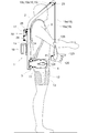
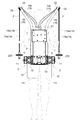
- FIGS. 1, 2, and 3 The overall configuration of the assist device and the main body 1 will be described. As shown in FIGS. 1, 2, and 3, the main body 1 is attached to the operator's back, the right and left arm 2 extending upward from the upper portion of the main body 1, and the lower portion of the main body 1.
- the right and left leg action portions 3 are provided, and an attachment belt 4 for attachment to an operator and right and left shoulder belts 5 are provided to constitute an assist device.
- the main body 1 includes a right and left vertical frame 6, support plates 7 and 8 connected across the upper and middle portions of the right and left vertical frames 6, right and left A horizontal frame 9 and the like connected to the lower part of the left vertical frame 6 are provided and configured in a frame shape.
- An attachment belt 4 is attached to the leg action part 3, and a shoulder belt 5 is attached to the vertical frame 6.
- a control device 14 is connected to the rear surface of the support plate 8, and a battery 16 is attached to the support plate 15 connected to the support plate 8 so as to cover the rear side of the control device 14.
- the operator's back (the shoulder) is placed on the shoulder belt 5 and the attachment belt 4 is wrapped around the waist of the worker and fixed.
- the body part 1 is attached to the part.
- the weight of the assist device and the luggage is mainly applied to the operator's waist through the attachment belt 4, and the weight of the assist device and the luggage depends on the waist of the operator. It is supported stably.
- the right and left shoulder belts 5 mainly exhibit a function of stopping the state in which the main body 1 is about to move backward from the back of the operator.
- the leg action unit 3 includes a base 10, a transmission case 11, an operation arm 12, a leg belt 13, and the like.
- a base 10 is supported by the horizontal frame 9 so as to be slidable in the left-right direction, and a transmission case 11 is connected to the outer end of the base 10 in a forward direction.
- an operation arm 12 is swingably supported around a horizontal axis P ⁇ b> 1 in the left-right direction at the front portion of the transmission case 11, and a wide belt-like leg belt 13 is formed.
- the end of the operation arm 12 is connected.
- a transmission mechanism (not shown) constituted by a plurality of spur gears is provided inside the transmission case 11, and an electric motor (not shown) is built in the left and right direction in the base 10, and the transmission mechanism is provided by the electric motor.
- the operating arm 12 is driven to swing around the horizontal axis P1.
- the right and left The leg action part 3 (base part 10) is movable in the left-right direction along the horizontal frame 9.
- the distance between the right and left leg action portions 3 is determined so as to match the physique of the operator, depending on how the attachment belt 4 is wrapped around the waist, and the right and left leg action portions 3 are determined by the attachment belt 4. The position is determined.
- the operator winds the leg belt 13 around the thigh and uses a hook and loop fastener (not shown) (trade name: Velcro (registered trademark)) to form the leg belt. Attach 13 to the thigh.
- a hook and loop fastener (trade name: Velcro (registered trademark)
- Velcro registered trademark
- the right and left arm portions 2 will be described. As shown in FIGS. 1, 2, and 3, the upper portions of the right and left vertical frames 6 extend diagonally upward on the diagonally front side beyond the right and left shoulders of the operator, and the right and left arms The portion 2 is configured, and a guide pulley 25 is rotatably supported on the upper end portion of the arm portion 2.
- a lifting device 17 is connected to the rear surface of the support plate 7, and the right two wires 18 and 19 and the two left wires 18 and 19 are connected from the lifting device 17.
- the receiving member 21 is connected to the upper part of the support plate 7, the receiving member 22 is connected to the upper part of the arm portion 2, and the outer 18 b and 19 b of the wires 18 and 19 are connected to the receiving members 21 and 22, , 19 are connected to the lifting device 17.
- the inner wires 18a and 19a of the right two wires 18 and 19 are hung on the guide pulley 25 and extended downward, and the right two wires 18 and 19,
- the right hand unit 20 is connected to the 19 inners 18a, 19a.
- Inner portions 18a and 19a of the left two wires 18 and 19 are hung on the guide pulley 25 and extended downward, and the left hand 18 and the inner portions 18a and 19a of the left two wires 18 and 19 are connected to the left hand.
- the unit 20 is connected.
- the elevating device 17 is connected to the support plate 7, and is connected horizontally to a vertically extending transmission case 30 that houses a transmission mechanism (not shown) and a lower portion of the transmission case 30.
- an electric motor 29 a support case 26 connected horizontally to the upper portion of the transmission case 30, and four rotating bodies (not shown) that are rotatable around a horizontal axis inside the support case 26 are provided. .
- the outer 18 b and 19 b of the wires 18 and 19 are connected to the receiving member 21, and the inner 18 a and 19 a of the wires 18 and 19 are the four rotating bodies inside the support case 26. Connected to each.
- the power of the electric motor 29 is transmitted to the rotating body inside the support case 26 via the transmission mechanism inside the transmission case 30, and the rotating body is wound. It is rotationally driven to the take-out side (upward side of the hand part 20) and the feeding side (downward side of the hand part 20).
- the electric motor 29 is provided with an electromagnetic brake (not shown). When the electric motor 29 is operated, the electromagnetic brake is released, and when the electric motor 29 is stopped or not energized, the electromagnetic brake is in a braking state.
- the right and left hand units 20 will be described. 4 to 7, the right hand unit 20 is shown, and the left hand unit 20 has a symmetrical shape with respect to the right hand unit 20.
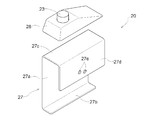
- the hand unit 20 includes a support member 27 formed by bending a metal plate and a cover 28 made of synthetic resin. The cover 28 is attached to the support member 27. ing.
- the cover 28 is provided with a raising operation switch 23 (corresponding to a manual operation unit), and in the left hand unit 20, the lowering operation switch 24 ( Equivalent to a manual operation unit).
- the raising and lowering operation switches 23 and 24 are connected to the control device 14 via a harness (not shown).
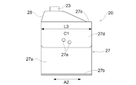
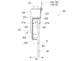
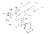
- a vertical wall-shaped lateral side portion 27 a As shown in FIGS. 4 and 5, in the support member 27, a vertical wall-shaped lateral side portion 27 a, a lower side portion 27 b that protrudes laterally from the lower portion of the lateral side portion 27 a, and an upper side of the lateral side portion 27 a And an inner portion 27d protruding downward from the upper portion 27c.
- a cover 28 is attached to the upper portion 27 c of the support member 27, and inner holes 27 d of the wires 18 and 19 are opened in the inner portion 27 d of the support member 27.
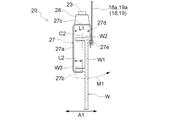
- the lower side protrudes laterally from the lower portion of the lateral side portion 27 a of the support member 27 with respect to the distance L1 in the lateral width direction A1 between the lateral side portion 27 a and the inner side portion 27 d of the support member 27.
- the protrusion length L2 of the part 27b is short.
- connection hole 27e of the support member 27 is provided in the lower portion of the inner portion 27d of the support member 27, and the longitudinal direction A2 (horizontal width) of the support member 27 (inner portion 27d and lower portion 27b). It is located in the central part C1 of the length L3 in the longitudinal direction A2) intersecting the direction A1.
- the lateral side portion 27a and the inner portion 27d of the support member 27 are connected.
- the wires 18 and 19 are connected to a portion closer to the inner portion 27d in the hand portion 20 than the central portion C2 in the horizontal width direction A1 (interval L1) therebetween.
- the operator pushes the up and down operation switches 23 and 24 with the thumbs of the right hand and the left hand.
- the ascending and descending operation switches 23 and 24 are configured to be returnable, and when the operator pushes the ascending and descending operation switches 23 and 24, the operation signals are received from the ascending and descending operation switches 23 and 24.
- the operation signals of the up / down operation switches 23, 24 are stopped.
- the lateral wall portion W1 of the case W is inserted between the lateral side portion 27a and the inner side portion 27d of the support member 27, and the lower side portion 2b of the support member 27 is placed in the case. It is allowed to enter the lower side of the protrusion W3 of W.
- the lateral side portion 27 a of the support member 27 is arranged in the vertical direction along the outside of the lateral wall portion W ⁇ b> 1 of the case W, and the lower side portion 2 b of the support member 27 is supported by the support member 27. It protrudes from the lower portion of the lateral side portion 27a to the lateral wall portion W1 side of the case W, and enters the lower side of the protruding portion W3 of the case W.
- the upper portion 27c of the support member 27 protrudes from the upper portion of the lateral side portion 27a of the support member 27 to the lateral wall portion W1 side of the case W, and is disposed above the protruding portion W2 of the case W.
- the inner portion 27d of the member 27 protrudes downward from the upper portion 27c of the support member 27 and is arranged in the vertical direction along the inner side of the lateral wall portion W1 of the case W.
- the lateral width of the protruding portion W3 of the case W is narrow in the lateral width direction A1.
- it protrudes laterally from the lower part of the lateral side portion 27a of the support member 27 with respect to the distance L1 in the lateral width direction A1 between the lateral side portion 27a and the inner side portion 27d of the support member 27. Since the protruding length L2 of the lower side portion 27b is short, the lower side portion 27b of the support member 27 easily enters the lower side of the protruding portion W3 of the case W.
- the support member 27 when the inner side 27d of the case 27 comes into contact with the inner side of the lateral wall part W1 of the case W, the lower side part 27b of the support member 27 tends to come out from the lower side of the protruding part W3 of the case W (the hand part 20 is The state of being detached from the lateral wall portion W1). This state is the same whether the lateral wall W1 of the case W has an opening or no opening.
- the support member 27 is caused by the moment M1.
- the state in which the lower side portion 27b of 27 is about to come out from the lower side of the protruding portion W3 of the case W is suppressed.
- the electromagnetic brake is released when the electric motor 29 is operated, and the electromagnetic brake is braked when the electric motor 29 is stopped and de-energized. It becomes a state.
- the electric motor 29 is stopped, the inner portions 18a and 19a of the wires 18 and 19 are not drawn out from the lifting device 17, and the weight of the case W is applied to the right and left hand portions 20 as will be described later. However, the right and left hand portions 20 do not descend.
- the operator lifts the case W from the floor by standing up with the right and left hand portions 20 attached to the lateral wall portion W1 of the case W.
- the right and left leg action portions 3 operation arms 12
- the operator's thighs are operated downward.
- the person's standing up is assisted.
- the right and left hand portions 20 (case W) are not lowered by the brake function of the electric motor 29 described above.
- the lifting / lowering device 17 operates to the winding side, the inners 18a and 19a of the wires 18 and 19 are wound, and the right and left hand portions 20 (case W) are raised.
- the lifting device 17 is stopped by stopping the pushing operation of the raising operation switch 23, and the right and left hand portions 20 (case W) are moved. Stop.
- the worker walks to a high shelf on which the case W is to be placed, a truck bed, or the like.
- the lifting device 17 operates to the feeding side, and the inners 18a, 19a of the wires 18, 19 are fed out.
- the right and left hand portions 20 (case W) are lowered.
- the case W is placed on a high shelf, a truck bed, or the like, and the right and left hand portions 20 are removed from the case W.
- the initial state is restored, and the same operation is performed on the next case W.
- the right and left hand units 20 will be described. 8 to 11, the right hand unit 20 is shown, and the left hand unit 20 has a symmetrical shape with respect to the right hand unit 20.
- the hand unit 20 includes a support member 27 formed by bending a metal plate and a cover 28 made of synthetic resin.
- the cover 28 is attached to the support member 27. ing.
- the cover 28 is provided with the raising operation switch 23, and in the left hand unit 20, the cover 28 is provided with the lowering operation switch 24 (see FIGS. 2 and 3).
- the raising and lowering operation switches 23 and 24 are connected to the control device 14 via a harness (not shown).
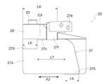
- the vertical wall-shaped lateral side portion 27a, the lower side portion 27b projecting laterally from the lower portion of the lateral side portion 27a, and the upper portion of the lateral side portion 27a As shown in FIGS. 8 and 9, in the support member 27, the vertical wall-shaped lateral side portion 27a, the lower side portion 27b projecting laterally from the lower portion of the lateral side portion 27a, and the upper portion of the lateral side portion 27a.
- An upper portion 27c that protrudes laterally from the front portion and an inner portion 27d that protrudes downward from the upper portion 27c are provided.
- the lower side protrudes laterally from the lower portion of the lateral side portion 27a of the support member 27 with respect to the distance L1 in the lateral width direction A1 between the lateral side portion 27a and the inner side portion 27d of the support member 27.
- the protrusion length L2 of the part 27b is short.
- the inner side of the support member 27 is located on the upper portion 27c of the front support member 27 with respect to the center portion C3 of the length L4 in the longitudinal direction A2 of the upper portion 27c of the support member 27.
- a portion 27d is provided.
- the inner portion 27d of the support member 27 has a length L5 that is shorter than the length L4 of the upper portion 27c of the support member 27 in the longitudinal direction A2.
- the support member 27 is located closer to the lateral side portion 27 a of the support member 27 on the rear side than the center portion C3 of the longitudinal direction A2 length L4 of the upper portion 27 c of the support member 27.
- a lower side portion 27b is provided.
- the lower side portion 27b of the support member 27 has a length L6 that is shorter than the length L4 in the longitudinal direction A2 of the upper side portion 27c of the support member 27.
- L6 is set to a short one. Accordingly, the inner side 27d of the support member 27 (the end on the lower side 27b side of the inner side 27d of the support member 27) and the lower side 27b of the support member 27 (the inner side of the lower side 27b of the support member 27). 27d side end), an interval L7 along the longitudinal direction A2 of the upper portion 27c of the support member 27 is generated.
- connection portion 27 f protrudes upward at the rear portion of the upper portion 27 c of the support member 27 and on the inner portion 27 d side of the support member 27, and the connection portion 27 f has a connection hole. 27e is opened, and the inners 18a and 19a of the wires 18 and 19 are connected to the connection hole 27e. Thereby, the connection part 27f and the connection hole 27e of the support member 27 are located substantially right above the lower part 27b of the support member 27 in a side view (see FIG. 9).
- the inner sides 18 a and 19 a of the wires 18 and 19 are connected to the connection portion 27 f (connection hole 27 e) of the support member 27, whereby the lateral side portion 27 a and the inner portion 27 d of the support member 27 are connected.
- the wires 18 and 19 are connected to a portion closer to the inner portion 27d in the hand portion 20 (support member 27) than the central portion C2 in the width direction A1 (interval L1) therebetween. ing.
- the center portion C3 in the longitudinal direction A2 of the upper portion 27c of the support member 27 intersecting the lateral width direction A1 is closer to one or the other end portion in the longitudinal direction A2 of the upper portion 27c of the support member 27 in the hand portion 20.
- the wires 18 and 19 are connected to the portion.
- the end on the lower side 27b side of the inner side 27d of the support member 27 and the end on the inner side 27d side of the lower side 27b of the support member 27 are connected by a straight line.
- the distance L8 (the diagonal distance L8 between the end on the lower side 27b side of the inner side 27d of the support member 27 and the end on the inner side 27d side of the lower side 27b of the support member 27) is wide. It has become. Accordingly, the posture of the hand unit 20 is set obliquely so that the interval L8 is in a state along the vertical direction, and the hand unit 20 is set to the oblique posture similar to that in FIG. 7 (see the previous item [6]). Thus, the hand portion 20 can be attached to the lateral wall portion W1 of the case W without difficulty.
- the lateral side portion 27 a of the support member 27 is arranged vertically along the outside of the lateral wall portion W ⁇ b> 1 of the case W, and the lower side portion 2 b of the support member 27 is supported by the support member 27. It protrudes from the lower portion of the lateral side portion 27a to the lateral wall portion W1 side of the case W, and enters the lower side of the protruding portion W3 of the case W.
- the upper portion 27c of the support member 27 protrudes from the upper portion of the lateral side portion 27a of the support member 27 toward the lateral wall portion W1 of the case W, and is disposed above the protruding portion W2 of the case W.
- the inner portion 27d of the member 27 protrudes downward from the upper portion 27c of the support member 27 and is arranged in the vertical direction along the inner side of the lateral wall portion W1 of the case W.
- the support member 27 when the inner side 27d of the case 27 comes into contact with the inner side of the lateral wall part W1 of the case W, the lower side part 27b of the support member 27 tends to come out from the lower side of the protruding part W3 of the case W (the hand part 20 is The state of being detached from the lateral wall portion W1). This state is the same whether the lateral wall W1 of the case W has an opening or no opening.
- the support member 27 is caused by the moment M1.
- the state in which the lower side portion 27b of 27 is about to come out from the lower side of the protruding portion W3 of the case W is suppressed.
- the support member 27 is located closer to the upper portion 27 c of the support member 27 on the rear side than the central portion C3 of the length L4 in the longitudinal direction A2 of the upper portion 27 c of the support member 27.
- An inner portion 27d is provided.
- the inner portion 27d of the support member 27 has a length L5 that is shorter than the length L4 of the upper portion 27c of the support member 27 in the longitudinal direction A2.
- the support member 27 is a portion of the upper portion 27 c of the front support member 27 with respect to the center portion C3 of the length L4 in the longitudinal direction A2 of the upper portion 27 c of the support member 27.
- a connecting portion 27f and a connecting hole 27e of the support member 27 are provided on the inner portion 27d side.
- connection portion 27 f connection hole 27 e
- Wires 18 and 19 are closer to the inner part 27d in the hand part 20 (supporting member 27) than the center part C2 (see FIG. 10) in the lateral width direction A1 (interval L1) between them and 27d. ) Is connected.
- the center portion C3 in the longitudinal direction A2 of the upper portion 27c of the support member 27 intersecting the lateral width direction A1 is closer to one or the other end portion in the longitudinal direction A2 of the upper portion 27c of the support member 27 in the hand portion 20.
- the wires 18 and 19 are connected to the portion.
- the lower side of the support member 27 is placed on the side portion 27a of the front support member 27.
- a side portion 27b is provided.
- the lower side portion 27b of the support member 27 has a length L6 that is shorter than the length L4 in the longitudinal direction A2 of the upper side portion 27c of the support member 27.
- connection portion 27 f and the connection hole 27 e of the support member 27, and the inner portion 27 d of the support member 27 in the longitudinal direction A2 of the upper portion 27 c of the support member 27 In this state, the lower portion 27b of the support member 27 is located. In this case, the lower side portion 27b of the support member 27 is provided at a position slightly forward (or slightly rearward) of the central portion C3 of the length L4 in the longitudinal direction A2 of the upper portion 27c of the support member 27. It may be configured.
- the lower portion 27 b of the support member 27 (the front portion of the lower portion 27 b) is pressed upward against the lower surface of the protruding portion W ⁇ b> 3 of the case W, and the upper portion 27 c ( The rear portion of the upper portion 27c is pressed downward against the upper surface of the protruding portion W2 of the case W.
- a frictional force is generated between the lower side portion 27b of the support member 27 (the front portion of the lower side portion 27b) and the lower surface of the protruding portion W3 of the case W, and the upper side portion 27c (upper side portion 27c) of the support member 27 is generated.
- the rear portion) and the upper surface of the protrusion W2 of the case W are in a state where a frictional force is generated.
- the lower side portion 27b of the support member 27 is configured as a separate member with respect to the lateral side portion 27a of the support member 27.
- Two bolts 27 g are connected to the lower side portion 27 b of the support member 27, and a plurality of connection holes 27 h are arranged in the vertical direction on the lateral side portion 27 a of the support member 27.
- the bolt 27 g of the lower side portion 27 b of the support member 27 is inserted into the connection hole 27 h of the lateral side portion 27 a of the support member 27, and the nut 31 is used to The lower side portion 27 b is connected to the lateral side portion 27 a of the support member 27.
- the connection hole 27h into which the bolt 27g of the lower side portion 27b of the support member 27 is inserted, the connection position of the lower side portion 27b in the lateral side portion 27a of the support member 27 can be changed up and down.
- the wires 18 and 19 are connected to the front part or the rear part of the inner part 27d of the support member 27 (the front side or the center part C1 of the length L3 in the longitudinal direction A2). You may comprise so that it may connect to a rear side.
- a moment M2 is generated to rotate the hand portion 20 around the lateral axis that intersects the lateral wall portion W1 of the case W (see FIG. 13).
- the wires 18 and 19 are connected to the portion on the inner side 27d side of the support member 27 in the upper side portion 27c of the support member 27 rather than the central portion C2. Also good.
- the center portion C1 of the length L3 in the longitudinal direction A2 of the support member 27 (the inner portion 27d and the lower portion 27b) the position in front of the center portion C1, the center portion C1. What is necessary is just to connect the wires 18 and 19 (inner 18a, 19a) to the position of the back rather than.
- the lower portion 27b is provided at the front portion of the lower portion of the lateral side portion 27a of the support member 27, and the upper portion is disposed at the rear portion of the upper portion of the lateral side portion 27a of the support member 27.
- the support member 27 in the portion of the upper portion 27c of the support member 27 on the front side of the center portion C3 of the length L4 in the longitudinal direction A2 of the upper portion 27c of the support member 27, includes an inner portion 27d, and is a portion of the upper portion 27c of the support member 27 on the rear side of the central portion C3 of the length L4 in the longitudinal direction A2 of the upper portion 27c of the support member 27, and the support member 27 may be provided with a connection portion 27f and a connection hole 27e of the support member 27 on the inner side portion 27d side.
- the lower portion 27b and the inner portion 27d of the support member 27 are formed in a quadrangular shape in plan view (side view). Instead of configuring, it may be configured in a semicircular shape or a trapezoidal shape.
- the lower side portion 27b and the inner side portion 27d of the support member 27 are completely separated along the longitudinal direction A2 of the upper side portion 27c of the support member 27 as shown in FIGS. Instead, a part of the base of the lower part 27b of the support member 27 (the part connected to the lateral part 27a of the support member 27) and the base of the inner part 27d of the support member 27 (the lateral side of the support member 27)
- the lower portion 27b and the inner portion 27d of the support member 27 may be separated so that a part of the portion connected to the portion 27a overlaps in plan view.
- the ascending operation switch 23 may be provided in the left hand unit 20 and the descending operation switch 24 may be provided in the right hand unit 20. Both the ascending and descending operation switches 23 and 24 may be provided in the right (left) hand unit 20.
- the right hand unit 20 shown in FIGS. 1, 2, and 3 may be provided with one wire 18, and the left hand unit 20 may be provided with one wire 18.
- the right and left arm portions 2 may be eliminated and one arm portion 2 may be provided.
- the two wires 18 are extended from one arm portion 2, the right hand portion 20 is provided on one of the two wires 18, and the left hand is placed on the other of the two wires 18.
- a hand unit 20 is provided.
- one wire 18 is extended from one arm portion 2, the end of one wire 18 is bifurcated, and a right hand portion 20 is provided on one of the branch portions.
- the left hand unit 20 is provided on the other side.
- the right and left hand portions 20 are provided.
- the right and left hand portions 20 can be attached to the case W by allowing the lower portion 27b of the support member 27 to enter the recesses of the lateral wall portion W1 of the case W.
- FIG. 14, FIG. 15 and FIG. 16 show an assist device including the hand unit 120 of the second embodiment. 17 and 18, the right hand unit 120 is shown, and the left hand unit 120 has a symmetrical shape with respect to the right hand unit 120.
- the right and left hand portions 120 are made of cloth gloves.
- the right and left hand portions 120 (gloves) are provided with a main body portion 127 into which an operator's palm (back of the hand) enters, and a belt-like (loop-like) connection portion 128 is provided at a portion of the main body portion 127 on the back side of the hand. It has been.
- the ends of the inners 18 a and 19 a of the right (left) wires 18 and 19 are passed through the connection part 128 of the right (left) hand part 120 (gloves), It is connected to the upper part of the inners 18a, 19a of the right (left) wires 18, 19 by a fixing bracket 138 (at the end of the inners 18a, 19a of the right (left) wires 18, 19 by the fixing bracket 138).
- a loop portion is formed, and the connection portion 128 of the right (left) hand portion 120 (gloves) is passed through the loop portion).
- the inner portions 18a and 19a of the right wires 18 and 19 are connected to the connecting portion 128 of the right hand portion 120 (gloves), and the left hand portion 120 (gloves) is connected to the left connecting portion 128 of the left hand portion 120 (gloves). Inners 18a and 19a of the wires 18 and 19 are connected.
- the right and left hand parts 120 are connected to the main body part 127 and are connected to the first finger part 131 into which the operator's thumb enters and the main body part 127.
- the second finger part 132 into which the operator's index finger enters, the third finger part 133 into which the operator's middle finger enters and the one connected to the main body part 127, and the ring finger of the operator into the body part 127.
- a fifth finger part 135 is provided which is connected to the fourth finger part 134 and the main body part 127 and into which an operator's little finger enters.
- the second finger portion 132 (corresponding to a specific finger portion of the right and left gloves) holds all the index fingers of the operator. It is configured to cover a bag.
- a rising operation switch 123 (corresponding to a manual operation unit) is provided in the second finger unit 132
- a lowering operation switch is provided in the second finger unit 132.
- 124 (corresponding to a manual operation unit) (see FIGS. 15 and 16).
- the raising and lowering operation switches 123 and 124 are connected to the control device 14 via a harness (not shown). In this case, the raising operation switch 123 (the lowering operation switch 124 (see FIGS. 15 and 16)) can be provided on the outside (outer surface) of the second finger portion 132.
- the first, third, fourth and fifth finger portions 131, 133, 134 and 135 are configured in a cylindrical shape instead of a bag shape, and is provided with openings 131a, 133a, 134a, 135a on the fingertip side.
- a synthetic rubber non-slip portion 136 is affixed to the palm portion of the main body 127 and the ventral side (palm side) of the first to fifth fingers 131 to 135.
- the index finger is covered with the second finger portion 132, and the thumb and middle fingers
- the fingertips of the ring finger and little finger are exposed from the openings 131a, 133a, 134a, and 135a of the first, third, fourth, and fifth finger portions 131, 133, 134, and 135.
- an operator wears right and left hand parts 120 (gloves) on the right hand and left hand, and the right hand (hand part 120) (gloves) and left hand (hand part 120) (gloves). ), The operator pushes the lifting operation switch 123 against the luggage with the right index finger, and pushes the lowering operation switch 124 against the luggage with the left index finger. Manipulate.
- the ascending and descending operation switches 123 and 124 are configured to be a pressure-sensitive type and a return type.
- an operation signal is output from the ascending / descending operation switches 123, 124, and the operator pushes the ascending / descending operation switches 123, 124.
- the operation signals of the up and down operation switches 123 and 124 are stopped.
- the electromagnetic brake is released when the electric motor 29 is operated, and the electromagnetic brake is braked when the electric motor 29 is stopped and de-energized. It becomes a state.
- the inners 18a and 19a of the wires 18 and 19 are not drawn out from the lifting device 17, and as will be described later, the right hand (hand part 120) (gloves) and the left hand (hand part) 120) Even if the weight of the load is applied to the (gloves), the right hand (hand part 120) (gloves) and the left hand (hand part 120) (gloves) do not descend.
- the operator holds the load with the right hand (hand unit 120) (gloves) and the left hand (hand unit 120) (gloves), and lifts the load from the floor by standing up.
- the operator pushes the raising operation switch 123, the right and left leg action portions 3 (operation arms 12) are driven downward, and the operator's thigh is operated downward, The person's standing up is assisted.
- the right hand (hand unit 120) (gloves) and the left hand (hand unit 120) (gloves) are not lowered by the brake function of the electric motor 129 described above.
- the lifting / lowering device 17 is operated to the winding side so that the inners 18a and 19a of the wires 18 and 19 are wound up, and the right hand (hand part 120) (gloves) and the left hand (hand part 120) (gloves) are opened.
- the lifting device 17 is stopped by stopping the pushing operation of the raising operation switch 123, and the right hand (hand unit). 120) (gloves) and the left hand (hand part 120) (gloves) stop.
- the worker walks to a high shelf or a truck bed where the luggage should be placed.
- the lifting device 17 operates to the feeding side, and the inners 18a and 19a of the wires 18 and 19 are fed out.
- the right hand (hand part 120) (gloves) and the left hand (hand part 20) (gloves) are lowered.
- the luggage is placed on a high shelf, a truck bed or the like, and the right hand (hand part 120) (gloves) and the left hand (hand part 120) (gloves) are separated from the luggage.
- the initial state is restored, and the same operation is performed on the next luggage.
- the right and left hand portions 120 (gloves) of the above (second embodiment) may be configured as shown in FIG.
- the second finger portion 132 is formed in a cylindrical shape instead of a bag shape (the opening portion 132a is provided on the fingertip side), and the raising operation switch 123 is provided.
- a fingertip portion 137 (corresponding to a specific finger portion) provided with a (lowering operation switch 124) is used as a separate member, and a second finger is formed by a hook-and-loop fastener (not shown) (trade name: Velcro (registered trademark)).
- the opening 132a of the part 132 is configured to be detachable. In this case, you may comprise so that the raising operation switch 123 (falling operation switch 124) may be provided in the exterior (outer surface) of the fingertip part 137.
- the state shown in FIG. 19 is a state in which the fingertip portion 137 is attached to the second finger portion 132 in the right and left hand portions 120 (gloves).
- the fingertip part 137 is changed to the opening part 131a of the first finger part 131 or the opening part 133a of the third finger part 133.
- it can attach to the opening part 134a of the 4th finger part 134, or the opening part 135a of the 5th finger part 135 with a hook-and-loop fastener (not shown) (brand name: Velcro (registered trademark)).
- the right and left hand portions 120 (gloves) of the above-described (second embodiment) may be configured as shown in FIG.
- the second finger portion 132 is formed in a cylindrical shape instead of a bag shape (the opening portion 132a is provided on the fingertip side).
- a cloth string portion 139 is connected to and extended from an edge portion of the opening 132 a of the second finger portion 132, and a cloth ring portion 140 is connected to the string portion 139.
- a rising operation switch 123 is provided on the inner surface (or outer surface) of the ring unit 140 of the second finger unit 132, and the left hand unit 120 (gloves).
- a lower operation switch 124 is provided on the inner surface (or outer surface) of the ring part 140 of the second finger part 132 (a manual operation part for raising is provided on the finger part of one of the right and left gloves, This corresponds to a state in which the lower and right glove fingers are provided with a manual operation unit for lowering).
- the string part 139 (ring part 40) is connected to the first finger part 131, the third finger part 133, the fourth finger part 134, or the fifth finger part 135 instead of the second finger part 132. You may comprise.
- the string part 139 (ring part 140) is configured to be detachable from the second finger part 132 in the same manner as the above-mentioned [first alternative form of the second embodiment], and the removed string part 139 (ring part) 140) may be configured to be attachable to and detachable from the first finger 131, the third finger 133, the fourth finger 134, or the fifth finger 135.
- the second finger portion 132 is not configured in a bag shape, but the first finger portion 131, the third finger portion 133, or The fourth finger part 134 or the fifth finger part 135 is formed in a bag shape, and the ascending operation switch 123 (the descending operation switch is provided on one of the first, third, fourth, and fifth finger parts 131, 133, 134, and 135. 124).
- one of the first to fifth finger portions 131 to 135 having a cylindrical shape having openings 131a to 135a is provided with a fingertip portion 137 having a lifting operation switch 123 (lowering operation switch 124) (string A portion 139 (ring portion 140) may be attached.
- the ascending operation switch 123 may be provided in the left hand unit 120 (gloves), and the descending operation switch 124 may be provided in the right hand unit 120 (gloves).
- the right hand unit 120 includes one wire 18, and the left hand unit 120 (gloves) includes one wire 18. May be.
- the right and left arm portions 2 may be eliminated and one arm portion 2 may be provided.
- the two wires 18 are extended from one arm portion 2, and the right hand portion 120 (gloves) is provided on one of the two wires 18, and the other of the two wires 18 is provided.
- the left hand part 120 (gloves) is provided.
- one wire 18 is extended from one arm portion 2 and the end of one wire 18 is bifurcated, and a right hand portion 120 (gloves) is provided on one of the branch portions, A left hand portion 120 (gloves) is provided on the other of the branch portions.
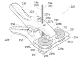
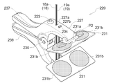
- the hand unit 220 is provided with a first holding arm 227 and a second holding arm 228.
- the first and second holding arms 227 and 228 are swingably connected to each other via a fulcrum pin 235, and the first and second holding arms 227 and 228 approach and separate from each other around the fulcrum pin 235.
- the operation arms 237 and 238 extend from the first and second holding arms 227 and 228 in the direction opposite to the extending direction of the first and second holding arms 227 and 228, respectively.
- a spring 236 that urges the operation arms 237 and 238 in a direction to separate them from each other (a direction in which the first and second holding arms 227 and 228 approach each other) is attached to the fulcrum pin 235 and the operation arms 237 and 238.
- the 1st and 2nd holding arms 227 and 228 (operation arms 237 and 238) are in a state like a clothespin.
- end portions of the first and second holding arms 227 and 228 are provided with holding portions 231 whose posture can be changed within a predetermined range.
- the holding part 231 is formed in a flat plate shape, and the bracket 231a and the pair of rubber bodies 231b are connected to each other.
- the holding portion 231 is supported by the bracket 231a of the holding portion 231 so as to freely swing around the axis P2 at the ends of the first and second holding arms 227 and 228.
- the first holding arm 227 is opened with an opening 227 a (corresponding to the first guide portion) (corresponding to the operating means) and an opening 227 b (corresponding to the operating means). Yes. Openings 228 a and 228 b are opened in the second holding arm 228.
- a U-shaped bracket 232 is connected to the openings 228a and 228b of the second holding arm 228, and a roller 233 (corresponding to the second guide portion) around the axis P3 of the bracket 232 (corresponding to the operating means) ) Is rotatably supported.
- the inners 18 a and 19 a of the wires 18 and 19 extend through the opening 227 a of the first holding arm 227 toward the second holding arm 228 (first The inner portion 18a, 19a of the wire 18, 19 is guided toward the second holding arm 228 while movement along the longitudinal direction of the inner portion 18a, 19a of the wire 18, 19 is allowed by the opening 227a of the first holding arm 227.
- the inners 18 a and 19 a of the wires 18 and 19 pass through the opening 228 a of the second holding arm 228, are wound around the roller 233, and pass through the opening 228 b of the second holding arm 228. And extends toward the first holding arm 227 (while the roller 233 of the second holding arm 228 allows movement along the longitudinal direction of the inners 18a, 19a of the wires 18, 19 while the wire 18 , 19 corresponds to a state in which the inners 18a, 19a are guided toward the first holding arm 227).
- the inners 18 a and 19 a of the wires 18 and 19 pass through the opening 228 b from the roller 233 of the second holding arm 228 and face the first holding arm 227, so that the first holding is performed. It passes through the opening 227b of the arm 227.
- a retaining member 234 (corresponding to an operating means) is attached to the ends of the inners 18a and 19a of the wires 18 and 19, and the inners 18a and 19a of the wires 18 and 19 come out of the opening 227b of the first holding arm 227. There is no state (a state connected to the first holding arm 27). As described above, the opening 227a and 227b of the first holding arm 27, the roller 233 of the second holding arm 228, the retaining member 234, and the like constitute the operating means.
- the first holding arm 227 is provided with a raising operation switch 223 (corresponding to a manual operation unit). As shown in FIG. 27, in the left hand unit 220, the first holding arm 227 is provided with a lowering operation switch 224 (corresponding to a manual operation unit).
- the raising and lowering operation switches 223 and 224 are connected to the control device 14 via a harness (not shown).
- the worker in a state where the worker wears the assist device, the worker has the right hand unit 220 with the right hand and the left hand unit 220 with the left hand.
- the ascending and descending operation switches 223 and 224 are pushed by the thumbs of the right hand and the left hand.
- the ascending / descending operation switches 223 and 224 are configured to return, and when the operator pushes the ascending / descending operation switches 223 and 224, operation signals from the ascending and descending operation switches 223 and 224 are displayed.
- the operation signals of the up / down operation switches 223, 224 are stopped.
- the first and second holding arms 227 and 228 are separated from each other by gripping the operating arms 237 and 238 so that the right and left hand portions 220 approach each other. 26 and 27, the first and second holding arms 227 and 228 hold the bag W so that one (the other) edge W1 is sandwiched therebetween.
- the urging force of the spring 236 shown in FIG. 25 holds the first and second holding arms 227 and 228 of the hand portion 220 so as to sandwich the edge portion W1 of the bag W.
- the bag W is held by the holding portion 231 without difficulty between the first and second holding arms 227, 228 of the hand portion 220.
- the first holding arm 227 of the hand unit 220 is extended upward from the opening 227 a of the first holding arm 227 to the inner portions 18 a and 19 a of the wires 18 and 19.
- the first holding arm 227 is located on the upper side
- the second holding arm 228 is located on the lower side
- the hand unit 220 is directed obliquely downward.
- the raising and lowering operation switches 223 and 224 are in a state of being positioned on the upper side.
- the first and second holding arms 227, 228 are changed from the inner portions 18a, 19a of the wires 18, 19 to the first and second holding arms 227, 228. Therefore, the edge W1 of the bag W is strongly held between the first and second holding arms 227 and 228 (holding portion 231).
- the first and second holding arms 227, 228 are moved from the inner portions 18a, 19a of the wires 18, 19 to the first and second holding arms 227, 228.
- the posture of the holding portion 231 changes around the axis P2 according to the shape of the edge W1 of the bag W, whereby the first and second holding arms 227, 228 are obtained.
- the bag W is easily held by the holding portion 231.
- the electromagnetic brake is released when the electric motor 29 is operated, and the electromagnetic brake is braked when the electric motor 29 is stopped and de-energized. It becomes a state.
- the electric motor 29 is stopped, the inner portions 18a and 19a of the wires 18 and 19 are not drawn out from the lifting device 17, and the weight of the bag W is applied to the right and left hand portions 20 as will be described later. Even so, the right and left hand portions 220 do not descend.
- the worker holds the right (left) hand portion 220 with the right hand (left hand), holds the bag W by the right and left hand portions 220, and lifts the bag W from the floor when the worker stands up.
- the operator pushes the raising operation switch 223, the right and left leg action portions 3 (operation arms 12) are driven downward, and the operator's thighs are operated downward.
- the person's standing up is assisted.
- the right and left hand portions 220 (bags W) are not lowered by the brake function of the electric motor 29 described above.
- the lifting / lowering device 17 operates to the winding side, the inners 18a and 19a of the wires 18 and 19 are wound, and the right and left hand portions 220 (bags W) are raised.
- the lifting operation switch 17 is stopped by stopping the pushing operation of the raising operation switch 223, and the right and left hand parts 220 (bags W) are moved. Stop.
- the worker walks to a high shelf on which bags W should be placed or a truck bed.
- the lifting device 17 is operated to the feeding side, and the inners 18a, 19a of the wires 18, 19 are fed out.
- the right and left hand portions 220 are lowered.
- the bag W is placed on a high shelf, a truck bed or the like, and the first and second holding arms 227, 227, 238 are operated by gripping the right and left hand portions 220 so that the operation arms 237, 238 are brought close to each other.
- the right and left hand portions 220 are removed from the bag W by separating the 228.
- the initial state is restored, and the same operation is performed on the next bag W.
- the hand unit 220 may be configured as shown in FIGS.
- the first and second holding arms 227 and 228 are formed by bending a round pipe, and the holding portion 231 is connected to the lower part of the first and second holding arms 227 and 228. (The posture of the holding portion 231 does not change).
- a bracket 239 is coupled to an upper portion of the first holding arm 227, and the first holding arm 227 (bracket 239) and the second holding arm 228 are connected to each other through a fulcrum pin 235 so as to be swingable.
- the first and second holding arms 227 and 228 are moved toward and away from each other around the fulcrum pin 235.
- the operation arm 238 extends from the second holding arm 228 toward the upper side of the first holding arm 227, and the operation arm 237 shown in FIGS.
- the 1 holding arm 227 is not provided. Accordingly, the first and second holding arms 227 and 228 can be separated by performing a grip operation so that the upper portion of the first holding arm 227 and the operation arm 238 are brought close to each other.
- a bracket 241 is connected to the second holding arm 228, and a spring receiving portion 239a is connected to the lower portion of the bracket 239.
- a spring 236 is attached across the fulcrum pin 235, the spring receiving portion 239a of the bracket 239, and the bracket 241, and the first and second holding arms 227 and 228 are urged by the spring 236 in a direction approaching each other.
- a roller 240 (corresponding to the first guide portion) (corresponding to the operation means) is rotatably supported by the bracket 241. 233 is rotatably supported.
- the bracket 242 is connected to the second holding arm 228.
- the second holding arm 228 (bracket 242) is provided with a raising operation switch 223, and in the left hand part 220, the second holding arm 228 (bracket 242) is provided with a lowering operation switch 224. Yes.
- the inners 18 a and 19 a of the wires 18 and 19 are wound around the roller 40 to change the direction and extend toward the second holding arm 228.
- Inners 18 a and 19 a of the wires 18 and 19 are wound around the roller 233 and extend from the second holding arm 228 toward the first holding arm 227.
- a bracket 243 is coupled to the first holding arm 227, and the inners 18a and 19a of the wires 18 and 19 are connected to the first holding arm 227 (bracket 243).
- the bag W is held between the first and second holding arms 227 and 228 so that the first and second holding arms 227 are held. , 228 holds the bag W.
- the hand unit 220 may be configured as shown in FIGS. 31 to 35.
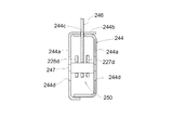
- a box-shaped (square tube-shaped) support portion 244 is configured by bending and connecting two sets of plate members, and extends over the vertical wall portion 244 a of the support portion 244.
- a fulcrum shaft 245 is connected.
- first and second holding arms 227 and 228 are made of a plate material, and a holding portion 231 is connected to the lower part of the first and second holding arms 227 and 228 ( The posture of the holding portion 231 does not change).
- boss portions 227c and 228c connected to the first and second holding arms 227 and 228 are rotatably supported by the fulcrum shaft 245.
- the first and second holding arms 227 and 228 are swingably supported by the support portion 244, and the first and second holding arms 227 and 228 are swung so as to approach and separate from each other. Move.
- arm-like operation portions 227d and 228d are connected to the boss portions 227c and 228c of the first and second holding arms 227 and 228, and the operation portions 227d and 228d are long. Holes 227e and 228e are opened.
- a spring 248 that biases the first and second holding arms 227 and 228 in the approaching direction is attached to the boss portions 227c and 228c and the operation portions 227d and 228d of the first and second holding arms 227 and 228.
- an opening 244 c is provided in the upper wall portion 244 b of the support portion 244, and a plate-like linkage member 246 is inserted into the opening portion 244 c of the support portion 244 so as to be movable up and down.
- a pin-like linking member 247 is connected to the lower part of the linking member 246, and the inners 18 a and 19 a of the wires 18 and 19 are connected to the upper part of the linking member 246.
- a vertical hole 244 d (corresponding to an approach side positioning portion and a separation side positioning portion) is opened in the vertical wall portion 244 a of the support portion 244.
- the linkage member 247 is inserted (connected) into the elongated holes 227e and 228e (operation portions 227d and 228d) of the first and second holding arms 227 and 228, and the linkage member 247 is also inserted into the elongated hole 244d of the support portion 244. Has been inserted.
- the linkage member 247 is inserted into the long holes 227 e and 228 e (operation portions 227 d and 228 d) of the first and second holding arms 227 and 228.
- the two holding arms 227 and 228 are linked to each other, and the first and second holding arms 227 and 228 are similarly operated on the approach side and similarly operated on the separation side.
- the operation means 250 is configured by the wires 18 and 19 (inners 18a and 19a), the linkage members 246 and 247, the operation portions 227d and 228d of the first and second holding arms 227, and the like.
- a fixed handle portion 249 is connected to the upper wall portion 244b of the support portion 244, and the handle portion 249 extends laterally toward the first holding arm 227 side. .
- the upper wall part 244 b of the support part 244 is provided with the raising operation switch 223, and in the left hand part 220, the upper wall part 244 b of the support part 244 is provided with the lowering operation switch 224. Yes.
- the state shown in FIG. 31 is a state in which the bag W is not held in the hand unit 220, and the first and second holding arms 227 and 228 are operated to the approach side by the spring 248.
- the first and second holding arms 227 and 228 are operated to the approach side, they are linked by the operation portions 227d and 228d of the first and second holding arms 227 and 228.
- the member 247 is raised, and the operation of the approaching side of the first and second holding arms 227 and 228 is stopped when the linkage member 247 hits the upper end portion of the long hole 244d of the support portion 244 (first and second). This corresponds to a state where the limit position on the approaching side of the holding arms 227 and 228 is determined on the approaching side).
- the operator can move the right and left hand portions 220 by holding the handle portion 249, and the ascending operation switch with the right hand (left hand) having the handle portion 249. 223 (lowering operation switch 224) can be operated.
- the operator When holding the bag W by the right and left hand portions 220, the operator holds the first holding arm 227 while holding the handle portion 249 so that the first holding arm 227 approaches the handle portion 249.
- the handle portion 249 and the first holding arm 227 are gripped and operated. Accordingly, the first holding arm 227 is operated to the separation side, and the second holding arm 228 is also operated to the separation side by the action of the linkage member 247.
- the first and second holding arms 227 and 228 By operating the first and second holding arms 227 and 228 to the separated side as described above, the first and second holding arms 227 and 228 are operated in the right and left hand portions 220 as shown in FIG. The bag W is held between the first and second holding arms 227 and 228 so that the bag W is held between them.
- the linkage member 247 is positioned at the upper and lower intermediate positions of the long hole 244d of the support portion 244.
- the linkage members 246 and 247 are raised with respect to the support portion 244 (linkage).
- the support portion 244 descends with respect to the members 246 and 247.
- the linkage member 247 causes the operating force to be applied to the first and second holding arms 227 and 228 by moving the first and second holding arms 227 and 228 closer to each other.
- the bag W is strongly held between the first and second holding arms 227 and 228.
- the linkage member 247 hits the upper end of the long hole 244d of the support portion 244, the operation on the approach side of the first and second holding arms 227, 228 is stopped (first and second). This corresponds to a state where the limit position on the approaching side of the holding arms 227 and 228 is determined on the approaching side).
- the second holding arm 228 is connected and fixed to the support portion 244 so as not to swing, and the inner portions 18a and 19a of the wires 18 and 19 are connected to the operation portion 227d of the first holding arm 227. Connect to.
- the ascending operation switch 223 may be provided in the left hand unit 220, and the descending operation switch 224 may be provided in the right hand unit 220. Both the raising and lowering operation switches 223 and 224 may be provided in the right (left) hand unit 220.
- 21 may be configured such that one wire 18 is provided for the right hand unit 220 shown in FIGS. 21, 22, and 23 and one wire 18 is provided for the left hand unit 220.
- the right and left arm portions 2 may be eliminated and one arm portion 2 may be provided.
- the two wires 18 are extended from one arm portion 2, the right hand portion 220 is provided on one of the two wires 18, and the left hand is placed on the other of the two wires 18.
- a hand unit 220 is provided.
- one wire 18 is extended from one arm portion 2 and the end of one wire 18 is bifurcated, and a right hand portion 220 is provided on one of the branch portions.
- the left hand unit 220 is provided on the other side.
- the approach side positioning part (separation side positioning part that determines the limit position on the separation side) that determines the limit position on the approach side of the first and second holding arms 227 and 228 in the above-mentioned [second modification of the third embodiment].
Landscapes
- Engineering & Computer Science (AREA)
- Mechanical Engineering (AREA)
- Life Sciences & Earth Sciences (AREA)
- Geology (AREA)
- Structural Engineering (AREA)
- Robotics (AREA)
- Manipulator (AREA)
Abstract
作業者が装着して使用するアシスト器具において、荷物の横壁部に開口部が備えられていない場合においても、荷物を適切に保持することができるハンド部を得る。 ハンド部20に、荷物の横壁部の外側に沿って上下方向に配置される横側部27aと、横側部27aの下部から荷物の横壁部側に突出して荷物の横壁部に入り込む下側部27bと、横側部27aの上部から荷物の横壁部側に突出して荷物の横壁部の上側に配置される上側部27cと、上側部27cから下側に突出して荷物の横壁部の内側に沿って上下方向に配置される内側部27dとが備えられている。
Description
本発明は、作業者が装着して使用するもので、作業者の作業(動作)を補助するアシスト器具に関する。
荷物を持ち上げて運んだりするアシスト器具として、特許文献1に開示されているものがある。
特許文献1では、作業者に取り付けられる本体部、本体部から前側に延出されたアーム部、アーム部から下側に延出されたワイヤ、作業者が手で持つことにより荷物を保持するものでワイヤに接続されたハンド部(特許文献1の図5,6,8,9の19)が備えられている。
特許文献1では、作業者に取り付けられる本体部、本体部から前側に延出されたアーム部、アーム部から下側に延出されたワイヤ、作業者が手で持つことにより荷物を保持するものでワイヤに接続されたハンド部(特許文献1の図5,6,8,9の19)が備えられている。
さらに、ワイヤを巻き取ることによりハンド部を上昇させ、ワイヤを繰り出すことによりハンド部を下降させる昇降装置、人為的に操作される手動操作部(特許文献1の図5及び図6の22,23)、手動操作部の操作信号に基づいて昇降装置を巻き取り側及び繰り出し側に作動させる制御装置が備えられている。
これにより、ハンド部に荷物を掛けた状態において(特許文献1の図5の(c)及び図6の(c)参照)、手動操作部を操作してハンド部を上昇及び下降させることによって、荷物を楽に持ち上げて運んだりすることができるのであり、作業者は荷物を安定させる為にハンド部を手で持つ状態となる。
特許文献1ではビールケース等のように、荷物の横壁部に開口部(特許文献1の図5,6,8,9参照)が備えられた荷物が想定されている。
これにより、ハンド部の下側部(特許文献1の図5の20c)を荷物の横壁部の開口部に挿入するのであり、ハンド部の下側部が荷物の横壁部から外れないように、上向きに折り曲げられた突出部(特許文献1の図5の20d)が、ハンド部の下側部に備えられている。
これにより、ハンド部の下側部(特許文献1の図5の20c)を荷物の横壁部の開口部に挿入するのであり、ハンド部の下側部が荷物の横壁部から外れないように、上向きに折り曲げられた突出部(特許文献1の図5の20d)が、ハンド部の下側部に備えられている。
荷物においては、前述のように、荷物の横壁部に開口部が備えられた荷物ばかりではなく、荷物の横壁部に開口部が備えられていない荷物もある。
本発明は、作業者が装着して使用するアシスト器具において、荷物の横壁部に開口部が備えられていない場合においても、荷物を適切に保持することができるハンド部を得ることを目的としている。
本発明は、作業者が装着して使用するアシスト器具において、荷物の横壁部に開口部が備えられていない場合においても、荷物を適切に保持することができるハンド部を得ることを目的としている。
また、荷物においては、ビールケース等のように同じ大きさ及び形状を備えた荷物ばかりではなく、各種の大きさや各種の形状を備えた荷物がある。
本発明は、作業者が装着して使用するアシスト器具において、各種の大きさや各種の形状を備えた荷物においても、荷物を適切に保持することができるハンド部を得ることを目的としている。
本発明は、作業者が装着して使用するアシスト器具において、各種の大きさや各種の形状を備えた荷物においても、荷物を適切に保持することができるハンド部を得ることを目的としている。
また、荷物においては、前述のビールケース等のようなハードケースばかりではなく、例えば米袋やセメント袋等のように、粉粒体を入れた布製やビニール製、紙製等の形状が変化し易い袋がある。
本発明は、作業者が装着して使用するアシスト器具において、例えば形状が変化し易い袋状の荷物においても、荷物を適切に保持することができるハンド部を得ることを目的としている。
本発明は、作業者が装着して使用するアシスト器具において、例えば形状が変化し易い袋状の荷物においても、荷物を適切に保持することができるハンド部を得ることを目的としている。
(構成)
本発明の特徴は、アシスト器具において次のように構成することにある。
作業者に取り付けられる本体部と、前記本体部から前側に延出されたアーム部と、
前記アーム部から下側に延出されたワイヤと、作業者が手で持つことにより荷物を保持するもので前記ワイヤに接続されたハンド部とが備えられ、
前記ワイヤを巻き取ることにより前記ハンド部を上昇させ、前記ワイヤを繰り出すことにより前記ハンド部を下降させる昇降装置と、
人為的に操作される手動操作部と、前記手動操作部の操作信号に基づいて前記昇降装置を巻き取り側及び繰り出し側に作動させる制御装置とが備えられており、
前記ハンド部に、
前記荷物の横壁部の外側に沿って上下方向に配置される横側部と、
前記横側部の下部から前記荷物の横壁部側に突出して前記荷物の横壁部に入り込む下側部と、
前記横側部の上部から前記荷物の横壁部側に突出して前記荷物の横壁部の上側に位置する上側部と、
前記上側部から下側に突出して前記荷物の横壁部の内側に沿って上下方向に配置される内側部とが備えられている。
本発明の特徴は、アシスト器具において次のように構成することにある。
作業者に取り付けられる本体部と、前記本体部から前側に延出されたアーム部と、
前記アーム部から下側に延出されたワイヤと、作業者が手で持つことにより荷物を保持するもので前記ワイヤに接続されたハンド部とが備えられ、
前記ワイヤを巻き取ることにより前記ハンド部を上昇させ、前記ワイヤを繰り出すことにより前記ハンド部を下降させる昇降装置と、
人為的に操作される手動操作部と、前記手動操作部の操作信号に基づいて前記昇降装置を巻き取り側及び繰り出し側に作動させる制御装置とが備えられており、
前記ハンド部に、
前記荷物の横壁部の外側に沿って上下方向に配置される横側部と、
前記横側部の下部から前記荷物の横壁部側に突出して前記荷物の横壁部に入り込む下側部と、
前記横側部の上部から前記荷物の横壁部側に突出して前記荷物の横壁部の上側に位置する上側部と、
前記上側部から下側に突出して前記荷物の横壁部の内側に沿って上下方向に配置される内側部とが備えられている。
(作用及び発明の効果)
本発明によると、ハンド部により荷物を保持する場合、ハンド部の横側部を荷物の横壁部の外側に沿わせて、ハンド部の下側部を荷物の横壁部に入り込ませる。この状態において、ハンド部の上側部を荷物の横壁部の上側に位置させ、ハンド部の内側部を荷物の横壁部の内側に沿わせる。
本発明によると、ハンド部により荷物を保持する場合、ハンド部の横側部を荷物の横壁部の外側に沿わせて、ハンド部の下側部を荷物の横壁部に入り込ませる。この状態において、ハンド部の上側部を荷物の横壁部の上側に位置させ、ハンド部の内側部を荷物の横壁部の内側に沿わせる。
これにより、荷物の重量がハンド部に掛かった場合、荷物の重量がハンド部の下側部によって支持されるのであり、ハンド部の下側部が荷物の横壁部から抜け出そうとしても(ハンド部が荷物の横壁部から外れようとしても)、ハンド部の内側部が荷物の横壁部の内側に当たることにより、ハンド部の下側部が荷物の横壁部から抜け出そうとする状態(ハンド部が荷物の横壁部から外れようとする状態)が抑えられる。この状態は、荷物の横壁部に開口部があっても、開口部が無くても同じである。
以上のように、荷物の横壁部に開口部があっても、開口部が無くても、ハンド部により荷物を適切に保持することができるようになって、アシスト器具の作業性を向上させることができる。
(構成)
本発明において、
前記横側部と前記内側部との間の横幅方向の中央部よりも、前記ハンド部における前記内側部に近い部分に、前記ワイヤが接続されていると好適である。
本発明において、
前記横側部と前記内側部との間の横幅方向の中央部よりも、前記ハンド部における前記内側部に近い部分に、前記ワイヤが接続されていると好適である。
(作用及び発明の効果)
本発明によれば、荷物の重量がハンド部の下側部に掛かり、ハンド部からワイヤに掛かると、ワイヤの張力により、ハンド部の下側部を荷物の横壁部に入り込ませようとするモーメントが発生する。
これにより、ハンド部の下側部が荷物の横壁部から抜け出そうとしても(ハンド部が荷物の横壁部から外れようとしても)、前述のモーメントにより、ハンド部の下側部が荷物の横壁部から抜け出そうとする状態(ハンド部が荷物の横壁部から外れようとする状態)が抑えられる。
本発明によれば、荷物の重量がハンド部の下側部に掛かり、ハンド部からワイヤに掛かると、ワイヤの張力により、ハンド部の下側部を荷物の横壁部に入り込ませようとするモーメントが発生する。
これにより、ハンド部の下側部が荷物の横壁部から抜け出そうとしても(ハンド部が荷物の横壁部から外れようとしても)、前述のモーメントにより、ハンド部の下側部が荷物の横壁部から抜け出そうとする状態(ハンド部が荷物の横壁部から外れようとする状態)が抑えられる。
(構成)
本発明において、
前記横幅方向と交差する前記上側部の長手方向の中央部よりも、前記ハンド部における前記上側部の長手方向の一方又は他方の端部側の部分に、前記ワイヤが接続されていると好適である。
本発明において、
前記横幅方向と交差する前記上側部の長手方向の中央部よりも、前記ハンド部における前記上側部の長手方向の一方又は他方の端部側の部分に、前記ワイヤが接続されていると好適である。
(作用及び発明の効果)
本発明によれば、荷物の重量がハンド部の下側部に掛かり、ハンド部からワイヤに掛かると、ワイヤの張力により、荷物の横壁部と交差する横向きの軸芯周りにハンド部を回転させようとするモーメントが発生する。
本発明によれば、荷物の重量がハンド部の下側部に掛かり、ハンド部からワイヤに掛かると、ワイヤの張力により、荷物の横壁部と交差する横向きの軸芯周りにハンド部を回転させようとするモーメントが発生する。
これにより、ハンド部の下側部(下側部の一部)が荷物の横壁部に上向きに押圧され、ハンド部の上側部(上側部の一部)が荷物の横壁部に下向きに押圧される状態となるのであり、ハンド部の下側部(下側部の一部)と荷物の横壁部との間に摩擦力が発生し、ハンド部の上側部(上側部の一部)と荷物の横壁部との間に摩擦力が発生する状態となる。
従って、ハンド部の下側部が荷物の横壁部から抜け出そうとしても(ハンド部が荷物の横壁部から外れようとしても)、前述の摩擦力により、ハンド部の下側部が荷物の横壁部から抜け出そうとする状態(ハンド部が荷物の横壁部から外れようとする状態)が抑えられる。
(構成)
本発明において、
前記横幅方向と交差する前記上側部の長手方向において、前記内側部と前記下側部との間に間隔が生じるように、前記内側部と前記下側部とが前記上側部の長手方向に沿って互いに離れて備えられていると好適である。
本発明において、
前記横幅方向と交差する前記上側部の長手方向において、前記内側部と前記下側部との間に間隔が生じるように、前記内側部と前記下側部とが前記上側部の長手方向に沿って互いに離れて備えられていると好適である。
(作用及び発明の効果)
ハンド部において、ハンド部の上側部から内側部が下側に突出していると、ハンド部の内側部と下側部との間隔が狭くなって、ハンド部を荷物の横壁部に取り付け難くなることが考えられる。
ハンド部において、ハンド部の上側部から内側部が下側に突出していると、ハンド部の内側部と下側部との間隔が狭くなって、ハンド部を荷物の横壁部に取り付け難くなることが考えられる。
本発明によると、ハンド部の内側部と下側部とが、ハンド部の上側部の長手方向に沿って互いに離れた状態となるので、ハンド部の内側部と下側部との間の斜め方向の間隔が広いものとなる。これにより、ハンド部の姿勢を斜めにすることにより(前述の斜め方向の間隔を上下方向に設定することにより)、ハンド部を無理なく荷物の横壁部に取り付けることができる。
(構成)
本発明において、
前記上側部の長手方向において、前記ワイヤが前記ハンド部に接続される部分と前記内側部との間に前記下側部が位置するように、前記ワイヤが前記ハンド部に接続される部分と、前記内側部と、前記下側部とが配置されていると好適である。
本発明において、
前記上側部の長手方向において、前記ワイヤが前記ハンド部に接続される部分と前記内側部との間に前記下側部が位置するように、前記ワイヤが前記ハンド部に接続される部分と、前記内側部と、前記下側部とが配置されていると好適である。
(作用及び発明の効果)
本発明によると、ワイヤがハンド部に接続される部分と内側部との間に下側部が位置しているので、荷物の重量がハンド部の下側部に掛かり、ハンド部からワイヤに掛かると、ワイヤの張力により、荷物の横壁部と交差する横向きの軸芯周りにハンド部を回転させようとするモーメントが発生する。
本発明によると、ワイヤがハンド部に接続される部分と内側部との間に下側部が位置しているので、荷物の重量がハンド部の下側部に掛かり、ハンド部からワイヤに掛かると、ワイヤの張力により、荷物の横壁部と交差する横向きの軸芯周りにハンド部を回転させようとするモーメントが発生する。
これにより、前述と同様に、ハンド部の下側部(下側部の一部)が荷物の横壁部に上向きに押圧され、ハンド部の上側部(上側部の一部)が荷物の横壁部に下向きに押圧される状態となるのであり、ハンド部の下側部(下側部の一部)と荷物の横壁部との間に摩擦力が発生し、ハンド部の上側部(上側部の一部)と荷物の横壁部との間に摩擦力が発生する状態となる。
従って、ハンド部の下側部が荷物の横壁部から抜け出そうとしても(ハンド部が荷物の横壁部から外れようとしても)、前述の摩擦力により、ハンド部の下側部が荷物の横壁部から抜け出そうとする状態(ハンド部が荷物の横壁部から外れようとする状態)が抑えられる。
(構成)
本発明の特徴は、アシスト器具において次のように構成することにある。
作業者に取り付けられる本体部と、前記本体部から前側に延出されたアーム部と、
前記アーム部から下側に延出されたワイヤと、荷物を保持するもので前記ワイヤに接続された右及び左のハンド部とが備えられ、
前記ワイヤを巻き取ることにより前記右及び左のハンド部を上昇させ、前記ワイヤを繰り出すことにより前記右及び左のハンド部を下降させる昇降装置と、
人為的に操作される上昇用及び下降用の手動操作部と、
前記上昇用の手動操作部の操作信号に基づいて前記昇降装置を巻き取り側に作動させ、前記下降用の手動操作部の操作信号に基づいて前記昇降装置を繰り出し側に作動させる制御装置とが備えられており、
前記右及び左のハンド部が手袋であり、前記右及び左の一方の手袋の指部に前記上昇用の手動操作部が備えられ、前記右及び左の他方の手袋の指部に前記下降用の手動操作部が備えられている。
本発明の特徴は、アシスト器具において次のように構成することにある。
作業者に取り付けられる本体部と、前記本体部から前側に延出されたアーム部と、
前記アーム部から下側に延出されたワイヤと、荷物を保持するもので前記ワイヤに接続された右及び左のハンド部とが備えられ、
前記ワイヤを巻き取ることにより前記右及び左のハンド部を上昇させ、前記ワイヤを繰り出すことにより前記右及び左のハンド部を下降させる昇降装置と、
人為的に操作される上昇用及び下降用の手動操作部と、
前記上昇用の手動操作部の操作信号に基づいて前記昇降装置を巻き取り側に作動させ、前記下降用の手動操作部の操作信号に基づいて前記昇降装置を繰り出し側に作動させる制御装置とが備えられており、
前記右及び左のハンド部が手袋であり、前記右及び左の一方の手袋の指部に前記上昇用の手動操作部が備えられ、前記右及び左の他方の手袋の指部に前記下降用の手動操作部が備えられている。
(作用及び発明の効果)
本発明によると、右及び左のハンド部が手袋であるので、作業者が右手及び左手に右及び左のハンド部(手袋)を装着した状態において、作業者は右手(ハンド部)(手袋)及び左手(ハンド部)(手袋)を自由に動かすことができる。これにより、各種の大きさや各種の形状を備えた荷物であっても、作業者は右手(ハンド部)(手袋)及び左手(ハンド部)(手袋)により荷物を適切に保持することができる。
本発明によると、右及び左のハンド部が手袋であるので、作業者が右手及び左手に右及び左のハンド部(手袋)を装着した状態において、作業者は右手(ハンド部)(手袋)及び左手(ハンド部)(手袋)を自由に動かすことができる。これにより、各種の大きさや各種の形状を備えた荷物であっても、作業者は右手(ハンド部)(手袋)及び左手(ハンド部)(手袋)により荷物を適切に保持することができる。
前述のように、作業者が右手(ハンド部)(手袋)及び左手(ハンド部)(手袋)により荷物を保持した状態において、昇降装置を巻き取り側及び繰り出し側に作動させることにより、右手(ハンド部)(手袋)及び左手(ハンド部)(手袋)、荷物を上昇及び下降させることができる。
本発明によると、昇降装置を巻き取り側及び繰り出し側に作動させる上昇用及び下降用の手動操作部が、右及び左のハンド部(手袋)の指部に備えられているので、作業者が右手及び左手に右及び左のハンド部(手袋)を装着した状態において、右手及び左手の指により上昇用及び下降用の手動操作部を無理なく操作することができる。
この場合、右及び左の一方のハンド部(手袋)の指部に、上昇用の手動操作部が備えられて、右及び左の他方のハンド部(手袋)の指部に、下降用の手動操作部が備えられている。
これにより、例えば作業者が右手の指で上昇用(下降用)の手動操作部を操作し、左手の指で下降用(上昇用)の手動操作部を操作する状態となり、上昇用及び下降用の手動操作部を別々の手の指で操作する状態となるので、例えば作業者が右手の指で上昇及び下降用の手動操作部の両方を同時に操作してしまうというような誤操作を伴うことがない。
これにより、例えば作業者が右手の指で上昇用(下降用)の手動操作部を操作し、左手の指で下降用(上昇用)の手動操作部を操作する状態となり、上昇用及び下降用の手動操作部を別々の手の指で操作する状態となるので、例えば作業者が右手の指で上昇及び下降用の手動操作部の両方を同時に操作してしまうというような誤操作を伴うことがない。
(構成)
本発明において、
前記右及び左の手袋の特定の指部に、前記上昇用及び下降用の手動操作部が備えられ、
前記右及び左の手袋の特定の指部以外の指部に、作業者の指が露出する開口部が備えられていると好適である。
本発明において、
前記右及び左の手袋の特定の指部に、前記上昇用及び下降用の手動操作部が備えられ、
前記右及び左の手袋の特定の指部以外の指部に、作業者の指が露出する開口部が備えられていると好適である。
(作用及び発明の効果)
本発明によると、右及び左のハンド部(手袋)において、上昇用及び下降用の手動操作部が備えられた特定の指部以外の指部に開口部が備えられており、作業者が右手及び左手に右及び左のハンド部(手袋)を装着した状態で、作業者の指が開口部から露出する状態となる。
本発明によると、右及び左のハンド部(手袋)において、上昇用及び下降用の手動操作部が備えられた特定の指部以外の指部に開口部が備えられており、作業者が右手及び左手に右及び左のハンド部(手袋)を装着した状態で、作業者の指が開口部から露出する状態となる。
これにより、作業者が右手(ハンド部)(手袋)及び左手(ハンド部)(手袋)により荷物を保持した状態において、作業者は右及び左のハンド部(手袋)の開口部から露出した指で荷物を直接に触れる状態となるので、作業者が右手及び左手に右及び左のハンド部(手袋)を装着した状態において、右手(ハンド部)(手袋)及び左手(ハンド部)(手袋)により荷物をさらに適切に保持することができる。
(構成)
本発明において、
前記右及び左の手袋の特定の指部が、前記右及び左の手袋の本体部から取り外し自在であり、前記右及び左の手袋の特定の指部を、前記右及び左の手袋の本体部において作業者の別の指に対応する部分に取り付け自在であると好適である。
本発明において、
前記右及び左の手袋の特定の指部が、前記右及び左の手袋の本体部から取り外し自在であり、前記右及び左の手袋の特定の指部を、前記右及び左の手袋の本体部において作業者の別の指に対応する部分に取り付け自在であると好適である。
(作用及び発明の効果)
本発明によると、上昇用及び下降用の手動操作部を備えた右及び左のハンド部(手袋)の指部の位置を、例えば右及び左のハンド部(手袋)の本体部の人差し指の位置や親指の位置、中指の位置等のように、作業者にとって作業が行い易い位置に変更することができる。
本発明によると、上昇用及び下降用の手動操作部を備えた右及び左のハンド部(手袋)の指部の位置を、例えば右及び左のハンド部(手袋)の本体部の人差し指の位置や親指の位置、中指の位置等のように、作業者にとって作業が行い易い位置に変更することができる。
(構成)
本発明において、
前記右及び左の手袋の本体部における手の甲側の部分に、前記ワイヤが接続される接続部が備えられていると好適である。
本発明において、
前記右及び左の手袋の本体部における手の甲側の部分に、前記ワイヤが接続される接続部が備えられていると好適である。
(作用及び発明の効果)
本発明によると、作業者が右手及び左手に右及び左のハンド部(手袋)を装着した状態において、右手(ハンド部)(手袋)及び左手(ハンド部)(手袋)により荷物を保持するのは、右手(ハンド部)(手袋)及び左手(ハンド部)(手袋)において手の平側である。
本発明によると、作業者が右手及び左手に右及び左のハンド部(手袋)を装着した状態において、右手(ハンド部)(手袋)及び左手(ハンド部)(手袋)により荷物を保持するのは、右手(ハンド部)(手袋)及び左手(ハンド部)(手袋)において手の平側である。
これにより、作業者が右手(ハンド部)(手袋)及び左手(ハンド部)(手袋)により荷物を保持する際に、ワイヤが手の平側に位置することはなく、作業者が右手(ハンド部)(手袋)及び左手(ハンド部)(手袋)により荷物を保持する際に、ワイヤが邪魔になることはない。
(構成)
本発明の特徴は、アシスト器具において次のように構成することにある。
作業者に取り付けられる本体部と、前記本体部から前側に延出されたアーム部と、
前記アーム部から下側に延出されたワイヤと、作業者が手で持つことにより荷物を保持するもので前記ワイヤに接続されたハンド部とが備えられ、
前記ワイヤを巻き取ることにより前記ハンド部を上昇させ、前記ワイヤを繰り出すことにより前記ハンド部を下降させる昇降装置と、
人為的に操作される手動操作部と、前記手動操作部の操作信号に基づいて前記昇降装置を巻き取り側及び繰り出し側に作動させる制御装置とが備えられており、
前記ハンド部に、互いに接近及び離間自在で、互いに接近することにより間に前記荷物を保持する第1保持アーム及び第2保持アームが備えられ、
前記第1及び第2保持アームが前記荷物を保持した状態で前記荷物の重量が前記第1及び第2保持アームに掛かると、前記荷物の重量により前記第1及び第2保持アームの少なくとも一方を接近側に操作する操作力を、前記ワイヤから前記第1及び第2保持アームの少なくとも一方に掛ける操作手段が備えられている。
本発明の特徴は、アシスト器具において次のように構成することにある。
作業者に取り付けられる本体部と、前記本体部から前側に延出されたアーム部と、
前記アーム部から下側に延出されたワイヤと、作業者が手で持つことにより荷物を保持するもので前記ワイヤに接続されたハンド部とが備えられ、
前記ワイヤを巻き取ることにより前記ハンド部を上昇させ、前記ワイヤを繰り出すことにより前記ハンド部を下降させる昇降装置と、
人為的に操作される手動操作部と、前記手動操作部の操作信号に基づいて前記昇降装置を巻き取り側及び繰り出し側に作動させる制御装置とが備えられており、
前記ハンド部に、互いに接近及び離間自在で、互いに接近することにより間に前記荷物を保持する第1保持アーム及び第2保持アームが備えられ、
前記第1及び第2保持アームが前記荷物を保持した状態で前記荷物の重量が前記第1及び第2保持アームに掛かると、前記荷物の重量により前記第1及び第2保持アームの少なくとも一方を接近側に操作する操作力を、前記ワイヤから前記第1及び第2保持アームの少なくとも一方に掛ける操作手段が備えられている。
(作用及び発明の効果)
本発明によると、ハンド部により荷物を保持する場合、ハンド部の第1及び第2保持アームの間に荷物を保持する。
この場合、荷物の重量がハンド部に掛かり、ワイヤに張力が発生すると、ワイヤからハンド部の第1及び第2保持アームの少なくとも一方に、ハンド部の第1及び第2保持アームの少なくとも一方を接近側に操作する操作力が掛かるのであり、ハンド部の第1及び第2保持アームの間で荷物が保持される。
本発明によると、ハンド部により荷物を保持する場合、ハンド部の第1及び第2保持アームの間に荷物を保持する。
この場合、荷物の重量がハンド部に掛かり、ワイヤに張力が発生すると、ワイヤからハンド部の第1及び第2保持アームの少なくとも一方に、ハンド部の第1及び第2保持アームの少なくとも一方を接近側に操作する操作力が掛かるのであり、ハンド部の第1及び第2保持アームの間で荷物が保持される。
以上のように、ハンド部の第1及び第2保持アームの間に荷物を保持するように構成した場合、荷物の重量を有効に利用することにより、例えば形状が変化し易い袋状の荷物であっても、ハンド部の第1及び第2保持アームの間で荷物が適切に保持されるようになって、アシスト器具の作業性を向上させることができる。
(構成)
本発明において、
前記操作手段は、
前記ワイヤを前記第2保持アームに向けて案内する第1案内部と、
前記ワイヤの長手方向に沿った前記ワイヤの移動を許容しながら前記ワイヤを前記第1保持アームに向けて案内するもので、前記第2保持アームに備えられた第2案内部とが、備えられており、
前記ワイヤが前記第1案内部から前記第2案内部を通り、前ワイヤの端部が前記第1保持アームに接続されて、
前記第1及び第2保持アームが前記荷物を保持した状態で前記荷物の重量が前記第1及び第2保持アームに掛かると、前記第1及び第2保持アームを接近側に操作する操作力が前記ワイヤから前記第1及び第2保持アームに掛かるようにすると好適である。
本発明において、
前記操作手段は、
前記ワイヤを前記第2保持アームに向けて案内する第1案内部と、
前記ワイヤの長手方向に沿った前記ワイヤの移動を許容しながら前記ワイヤを前記第1保持アームに向けて案内するもので、前記第2保持アームに備えられた第2案内部とが、備えられており、
前記ワイヤが前記第1案内部から前記第2案内部を通り、前ワイヤの端部が前記第1保持アームに接続されて、
前記第1及び第2保持アームが前記荷物を保持した状態で前記荷物の重量が前記第1及び第2保持アームに掛かると、前記第1及び第2保持アームを接近側に操作する操作力が前記ワイヤから前記第1及び第2保持アームに掛かるようにすると好適である。
(作用及び発明の効果)
本発明によると、ワイヤが第1案内部からハンド部の第2保持アームの第2案内部を通り、ハンド部の第1保持アームに接続されている。
これにより、荷物の重量がハンド部に掛かり、ワイヤに張力が発生すると、ハンド部において、ワイヤにより第1保持アームが第2保持アーム(第2案内部)に向けて操作されるのであり、ワイヤにより第2保持アーム(第2案内部)が第1保持アームに向けて操作される。
以上のように、ワイヤの簡単な配置により、操作手段を構成することができて、アシスト器具の構造の簡素化の面で有利なものとなる。
本発明によると、ワイヤが第1案内部からハンド部の第2保持アームの第2案内部を通り、ハンド部の第1保持アームに接続されている。
これにより、荷物の重量がハンド部に掛かり、ワイヤに張力が発生すると、ハンド部において、ワイヤにより第1保持アームが第2保持アーム(第2案内部)に向けて操作されるのであり、ワイヤにより第2保持アーム(第2案内部)が第1保持アームに向けて操作される。
以上のように、ワイヤの簡単な配置により、操作手段を構成することができて、アシスト器具の構造の簡素化の面で有利なものとなる。
(構成)
本発明において、
前記第1案内部は、前記ワイヤの長手方向に沿った前記ワイヤの移動を許容しながら前記ワイヤを前記第2保持アームに向けて案内するもので、前記第1保持アームに備えられており、
前記手動操作部が前記第1保持アームに備えられていると好適である。
本発明において、
前記第1案内部は、前記ワイヤの長手方向に沿った前記ワイヤの移動を許容しながら前記ワイヤを前記第2保持アームに向けて案内するもので、前記第1保持アームに備えられており、
前記手動操作部が前記第1保持アームに備えられていると好適である。
(作用及び発明の効果)
前述のように、ワイヤが第1案内部からハンド部の第2保持アームの第2案内部を通って、ハンド部の第1保持アームに接続される場合、本発明によると、第1案内部は、ワイヤの長手方向に沿ったワイヤの移動を許容しながらワイヤをハンド部の第2保持アームに向けて案内するものであり、ハンド部の第1保持アームに備えられている。
前述のように、ワイヤが第1案内部からハンド部の第2保持アームの第2案内部を通って、ハンド部の第1保持アームに接続される場合、本発明によると、第1案内部は、ワイヤの長手方向に沿ったワイヤの移動を許容しながらワイヤをハンド部の第2保持アームに向けて案内するものであり、ハンド部の第1保持アームに備えられている。
これにより、アーム部から下側に延出されたワイヤが、ハンド部の第1保持アームの第1案内部を通り下側に延出され、ハンド部の第2保持アームの第2案内部により上側に向きを変えて、ハンド部の第1保持アームに接続される状態となるのであり、ハンド部の第1保持アームが上側に位置し、ハンド部の第2保持アームが下側に位置する状態となる。
従って、手動操作部をハンド部の第1保持アームに備えることにより、上側に位置するハンド部の第1保持アームの手動操作部を、容易に操作することができるようになって、アシスト器具の作業性を向上させることができる。
従って、手動操作部をハンド部の第1保持アームに備えることにより、上側に位置するハンド部の第1保持アームの手動操作部を、容易に操作することができるようになって、アシスト器具の作業性を向上させることができる。
(構成)
本発明において、
前記第1及び第2保持アームを人為的に離間させる為の操作アームが、前記第1及び第2保持アームから延出されていると好適である。
本発明において、
前記第1及び第2保持アームを人為的に離間させる為の操作アームが、前記第1及び第2保持アームから延出されていると好適である。
(作用及び発明の効果)
ハンド部の第1及び第2保持アームの間に荷物を保持した状態において、ハンド部を荷物から取り外す場合、本発明によると、ハンド部の第1及び第2保持アームから延出される操作アームを操作することにより、ハンド部の第1及び第2保持アームを離間させて、ハンド部の第1及び第2保持アームから荷物を容易に取り外すことができる。
ハンド部の第1及び第2保持アームの間に荷物を保持した状態において、ハンド部を荷物から取り外す場合、本発明によると、ハンド部の第1及び第2保持アームから延出される操作アームを操作することにより、ハンド部の第1及び第2保持アームを離間させて、ハンド部の第1及び第2保持アームから荷物を容易に取り外すことができる。
(構成)
本発明において、
前記ハンド部に、前記第1及び第2保持アームを支持する支持部が備えられて、
前記第1及び第2保持アームが互いに接近及び離間するように、前記第1及び第2保持アームの少なくとも一方が前記支持部に揺動自在に支持されており、
前記操作手段は、
前記第1及び第2保持アームのうちの揺動するものに備えられた操作部に前記ワイヤが接続されて、前記第1及び第2保持アームが前記荷物を保持した状態で前記荷物の重量が前記第1及び第2保持アームに掛かると、前記荷物の重量により前記第1及び第2保持アームのうちの揺動するものを接近側に操作する操作力が、前記ワイヤから前記操作部を介して前記第1及び第2保持アームのうちの揺動するものに掛かるようにすると好適である。
本発明において、
前記ハンド部に、前記第1及び第2保持アームを支持する支持部が備えられて、
前記第1及び第2保持アームが互いに接近及び離間するように、前記第1及び第2保持アームの少なくとも一方が前記支持部に揺動自在に支持されており、
前記操作手段は、
前記第1及び第2保持アームのうちの揺動するものに備えられた操作部に前記ワイヤが接続されて、前記第1及び第2保持アームが前記荷物を保持した状態で前記荷物の重量が前記第1及び第2保持アームに掛かると、前記荷物の重量により前記第1及び第2保持アームのうちの揺動するものを接近側に操作する操作力が、前記ワイヤから前記操作部を介して前記第1及び第2保持アームのうちの揺動するものに掛かるようにすると好適である。
(作用及び発明の効果)
本発明によると、ワイヤがハンド部の第1及び第2保持アームのうちの揺動するものの操作部に接続されている。
これにより、荷物の重量がハンド部に掛かり、ワイヤに張力が発生すると、ワイヤによりハンド部の第1及び第2保持アームのうちの揺動するものが接近側に操作されるのであり、ハンド部の第1及び第2保持アームの間で荷物が保持される。
以上のように、ワイヤの簡単な配置により、操作手段を構成することができて、アシスト器具の構造の簡素化の面で有利なものとなる。
本発明によると、ワイヤがハンド部の第1及び第2保持アームのうちの揺動するものの操作部に接続されている。
これにより、荷物の重量がハンド部に掛かり、ワイヤに張力が発生すると、ワイヤによりハンド部の第1及び第2保持アームのうちの揺動するものが接近側に操作されるのであり、ハンド部の第1及び第2保持アームの間で荷物が保持される。
以上のように、ワイヤの簡単な配置により、操作手段を構成することができて、アシスト器具の構造の簡素化の面で有利なものとなる。
(構成)
本発明において、
前記支持部に、前記第1及び第2保持アームの両方が互いに接近及び離間するように揺動自在に支持され、
前記第1保持アームの前記操作部と前記第2保持アームの前記操作部とに亘って共通の連係部材が接続されて、
前記第1及び第2保持アームが互いに接近及び離間するように、前記連係部材により前記第1及び第2保持アームが揺動すると好適である。
本発明において、
前記支持部に、前記第1及び第2保持アームの両方が互いに接近及び離間するように揺動自在に支持され、
前記第1保持アームの前記操作部と前記第2保持アームの前記操作部とに亘って共通の連係部材が接続されて、
前記第1及び第2保持アームが互いに接近及び離間するように、前記連係部材により前記第1及び第2保持アームが揺動すると好適である。
(作用及び発明の効果)
ハンド部の第1及び第2保持アームの両方を互いに接近及び離間するように揺動自在に支持部に支持した場合、本発明によると、連係部材によりハンド部の第1及び第2保持アームが連係されているので、ハンド部の第1及び第2保持アームが同じように接近側に操作され、同じように離間側に操作されるようになる。
これにより、ハンド部による荷物の保持及び荷物を離すことが円滑に行われるようになって、アシスト器具の作業性を向上させることができる。
ハンド部の第1及び第2保持アームの両方を互いに接近及び離間するように揺動自在に支持部に支持した場合、本発明によると、連係部材によりハンド部の第1及び第2保持アームが連係されているので、ハンド部の第1及び第2保持アームが同じように接近側に操作され、同じように離間側に操作されるようになる。
これにより、ハンド部による荷物の保持及び荷物を離すことが円滑に行われるようになって、アシスト器具の作業性を向上させることができる。
(構成)
本発明において、
前記ワイヤが前記連係部材に接続されており、
前記第1及び第2保持アームが前記荷物を保持した状態で前記荷物の重量が前記第1及び第2保持アームに掛かると、前記荷物の重量により前記第1及び第2保持アームを接近側に操作する操作力が、前記ワイヤから前記連係部材及び前記操作部を介して前記第1及び第2保持アームに掛かるようにすると好適である。
本発明において、
前記ワイヤが前記連係部材に接続されており、
前記第1及び第2保持アームが前記荷物を保持した状態で前記荷物の重量が前記第1及び第2保持アームに掛かると、前記荷物の重量により前記第1及び第2保持アームを接近側に操作する操作力が、前記ワイヤから前記連係部材及び前記操作部を介して前記第1及び第2保持アームに掛かるようにすると好適である。
(作用及び発明の効果)
前述のように、連係部材によりハンド部の第1及び第2保持アームが連係されて、ハンド部の第1及び第2保持アームが同じように接近側に操作され、同じように離間側に操作される状態において、本発明によると、ワイヤが連係部材に接続されている。
これにより、ワイヤを連係部材に接続するという簡単な構造によって、連係部材を介してハンド部の第1及び第2保持アームを接近側に操作するように、操作手段を構成することができて、アシスト器具の構造の簡素化の面で有利なものとなる。
前述のように、連係部材によりハンド部の第1及び第2保持アームが連係されて、ハンド部の第1及び第2保持アームが同じように接近側に操作され、同じように離間側に操作される状態において、本発明によると、ワイヤが連係部材に接続されている。
これにより、ワイヤを連係部材に接続するという簡単な構造によって、連係部材を介してハンド部の第1及び第2保持アームを接近側に操作するように、操作手段を構成することができて、アシスト器具の構造の簡素化の面で有利なものとなる。
(構成)
本発明において、
前記支持部に固定の持ち手部が備えられていると好適である。
本発明において、
前記支持部に固定の持ち手部が備えられていると好適である。
(作用及び発明の効果)
本発明によると、アシスト器具を装着した作業者が持ち手部を持ってハンド部を移動させることにより、ハンド部の第1及び第2保持アームを荷物の位置に無理なく移動させることができ、荷物を保持したハンド部を所望の位置に無理なく移動させることができるようになって、アシスト器具の作業性を向上させることができる。
本発明によると、アシスト器具を装着した作業者が持ち手部を持ってハンド部を移動させることにより、ハンド部の第1及び第2保持アームを荷物の位置に無理なく移動させることができ、荷物を保持したハンド部を所望の位置に無理なく移動させることができるようになって、アシスト器具の作業性を向上させることができる。
(構成)
本発明において、
前記支持部に前記手動操作部が備えられていると好適である。
本発明において、
前記支持部に前記手動操作部が備えられていると好適である。
(作用及び発明の効果)
前述のように、アシスト器具を装着した作業者が持ち手部を持った場合、本発明によると、持ち手部を持った手で手動操作部を操作することができるようになるので、アシスト器具の作業性を向上させることができる。
前述のように、アシスト器具を装着した作業者が持ち手部を持った場合、本発明によると、持ち手部を持った手で手動操作部を操作することができるようになるので、アシスト器具の作業性を向上させることができる。
(構成)
本発明において、
前記第1及び第2保持アームのうちの接近側に操作されるものの接近側の限界位置を決める接近側位置決め部が備えられていると好適である。
本発明において、
前記第1及び第2保持アームのうちの接近側に操作されるものの接近側の限界位置を決める接近側位置決め部が備えられていると好適である。
(作用及び発明の効果)
本発明によると、ハンド部の第1及び第2保持アームの間で荷物が保持された状態において、決める接近側位置決め部により、ハンド部の第1及び第2保持アームの間で荷物を必要以上に締め付けてしまう状態を防止することができるのであり、ハンド部の第1及び第2保持アームの間で荷物が破損するような状態を防止することができる。
本発明によると、ハンド部の第1及び第2保持アームの間で荷物が保持された状態において、決める接近側位置決め部により、ハンド部の第1及び第2保持アームの間で荷物を必要以上に締め付けてしまう状態を防止することができるのであり、ハンド部の第1及び第2保持アームの間で荷物が破損するような状態を防止することができる。
(構成)
本発明において、
前記第1及び第2保持アームのうちの離間側に操作されるものの離間側の限界位置を決める離間側位置決め部が備えられていると好適である。
本発明において、
前記第1及び第2保持アームのうちの離間側に操作されるものの離間側の限界位置を決める離間側位置決め部が備えられていると好適である。
(作用及び発明の効果)
本発明によると、ハンド部の第1及び第2保持アームの間で荷物が保持された状態において、離間側位置決め部により、ハンド部の第1及び第2保持アームを必要以上に離間させてしまう状態を防止することができるのであり、これによってハンド部から荷物を円滑に離すことができる。
本発明によると、ハンド部の第1及び第2保持アームの間で荷物が保持された状態において、離間側位置決め部により、ハンド部の第1及び第2保持アームを必要以上に離間させてしまう状態を防止することができるのであり、これによってハンド部から荷物を円滑に離すことができる。
(構成)
本発明において、
前記荷物に馴染むように姿勢変更自在な保持部が、前記第1及び第2保持アームに備えられて、前記保持部により前記荷物が保持されると好適である。
本発明において、
前記荷物に馴染むように姿勢変更自在な保持部が、前記第1及び第2保持アームに備えられて、前記保持部により前記荷物が保持されると好適である。
(作用及び発明の効果)
ハンド部の第1及び第2保持アームの間に荷物を保持する場合、本発明によると、荷物に馴染むように姿勢変更自在な保持部が、ハンド部の第1及び第2保持アームに備えられている。
これにより、ハンド部の第1及び第2保持アームの少なくとも一方を接近側に操作する操作力が掛かった場合に、荷物の形状に応じて保持部の姿勢が変化することによって、ハンド部の第1及び第2保持アームの間で保持部により荷物が無理なく保持されるようになる。
ハンド部の第1及び第2保持アームの間に荷物を保持する場合、本発明によると、荷物に馴染むように姿勢変更自在な保持部が、ハンド部の第1及び第2保持アームに備えられている。
これにより、ハンド部の第1及び第2保持アームの少なくとも一方を接近側に操作する操作力が掛かった場合に、荷物の形状に応じて保持部の姿勢が変化することによって、ハンド部の第1及び第2保持アームの間で保持部により荷物が無理なく保持されるようになる。
(第1実施形態)
本発明の実施形態における前後方向及び左右方向は、特段の説明がない限り、以下のように記載している。作業者がアシスト器具を装着した状態において、作業者から視て前側が「前」であり、後側が「後」であり、右側が「右」であり、左側が「左」である。
本発明の実施形態における前後方向及び左右方向は、特段の説明がない限り、以下のように記載している。作業者がアシスト器具を装着した状態において、作業者から視て前側が「前」であり、後側が「後」であり、右側が「右」であり、左側が「左」である。
[1]
アシスト器具の全体構成及び本体部1について説明する。
図1,2,3に示すように、作業者の背中部に取り付けられる本体部1、本体部1の上部から上側に延出された右及び左のアーム部2、本体部1の下部に備えられた右及び左の脚作用部3が備えられており、作業者への装着用の取付ベルト4、右及び左の肩ベルト5が備えられて、アシスト器具が構成されている。
アシスト器具の全体構成及び本体部1について説明する。
図1,2,3に示すように、作業者の背中部に取り付けられる本体部1、本体部1の上部から上側に延出された右及び左のアーム部2、本体部1の下部に備えられた右及び左の脚作用部3が備えられており、作業者への装着用の取付ベルト4、右及び左の肩ベルト5が備えられて、アシスト器具が構成されている。
図1,2,3に示すように、本体部1は、右及び左の縦フレーム6、右及び左の縦フレーム6の上部及び中間部に亘って連結された支持板7,8、右及び左の縦フレーム6の下部に亘って連結された横フレーム9等を備えて、枠状に構成されている。脚作用部3に取付ベルト4が取り付けられており、縦フレーム6に肩ベルト5が取り付けられている。支持板8の後面に制御装置14が連結されており、制御装置14の後側を覆うように支持板8に連結された支持板15に、バッテリー16が取り付けられている。
これにより、図1,2,3に示すように、肩ベルト5に作業者の腕部(肩部)を入れ、取付ベルト4を作業者の腰部に巻き付けて固定することにより、作業者の背中部に本体部1が取り付けられる。
図1,2,3に示すように、アシスト器具及び荷物の重量が取付ベルト4を介して主に作業者の腰部に掛かることになるのであり、アシスト器具及び荷物の重量が作業者の腰部により安定して支持される。右及び左の肩ベルト5は、主に本体部1が作業者の背中部から後方に離れようとする状態を止める機能を発揮する。
[2]
次に、右及び左の脚作用部3について説明する。
図1,2,3に示すように、脚作用部3は、基部10、伝動ケース11、操作アーム12及び脚ベルト13等を備えている。横フレーム9に左右方向にスライド自在に基部10が支持されており、基部10の外端部に伝動ケース11が前向きに連結されている。
次に、右及び左の脚作用部3について説明する。
図1,2,3に示すように、脚作用部3は、基部10、伝動ケース11、操作アーム12及び脚ベルト13等を備えている。横フレーム9に左右方向にスライド自在に基部10が支持されており、基部10の外端部に伝動ケース11が前向きに連結されている。
図1,2,3に示すように、伝動ケース11の前部の左右方向の横軸芯P1周りに、操作アーム12が揺動自在に支持されており、幅広のベルト状の脚ベルト13が操作アーム12の端部に連結されている。複数の平ギヤにより構成された伝動機構(図示せず)が伝動ケース11の内部に備えられ、電動モータ(図示せず)が基部10に左右方向に内装されており、電動モータにより伝動機構を介して操作アーム12が横軸芯P1周りに揺動駆動される。
前項[1]に記載のように、作業者の背中部に本体部1を取り付ける場合において、作業者が取付ベルト4を腰部に巻き付けて固定する際、取付ベルト4と一緒に、右及び左の脚作用部3(基部10)が横フレーム9に沿って左右方向に移動可能である。
これにより、取付ベルト4の腰部への巻き付け具合により、作業者の体格に合わせるように右及び左の脚作用部3の間隔が決まるのであり、取付ベルト4により右及び左の脚作用部3の位置が決められた状態となる。
これにより、取付ベルト4の腰部への巻き付け具合により、作業者の体格に合わせるように右及び左の脚作用部3の間隔が決まるのであり、取付ベルト4により右及び左の脚作用部3の位置が決められた状態となる。
この後、図1,2,3に示すように、作業者は脚ベルト13を太腿部に巻き付けて、面ファスナ(図示せず)(商品名:マジックテープ(登録商標))により、脚ベルト13を太腿部に取り付ける。
作業者がアシスト器具を装着した状態において、作業者の腰部の右側に右の脚作用部3(伝動ケース11)が位置し、作業者の腰部の左側に左の脚作用部3(伝動ケース11)が位置する。
作業者がアシスト器具を装着した状態において、作業者の腰部の右側に右の脚作用部3(伝動ケース11)が位置し、作業者の腰部の左側に左の脚作用部3(伝動ケース11)が位置する。
[3]
次に、右及び左のアーム部2について説明する。
図1,2,3に示すように、右及び左の縦フレーム6の上部が、作業者の右及び左の肩部を越えて斜め前側の斜め上側に延出されて、右及び左のアーム部2が構成されており、アーム部2の上端部に案内プーリー25が回転自在に支持されている。
次に、右及び左のアーム部2について説明する。
図1,2,3に示すように、右及び左の縦フレーム6の上部が、作業者の右及び左の肩部を越えて斜め前側の斜め上側に延出されて、右及び左のアーム部2が構成されており、アーム部2の上端部に案内プーリー25が回転自在に支持されている。
図1,2,3に示すように、支持板7の後面に昇降装置17が連結されており、昇降装置17から、右の2本のワイヤ18,19及び左の2本のワイヤ18,19が延出されている。支持板7の上部に受け部材21が連結され、アーム部2の上部に受け部材22が連結されており、ワイヤ18,19のアウター18b,19bが受け部材21,22に接続されて、ワイヤ18,19のインナー18a,19aが昇降装置17に接続されている。
図1,2,3に示すように、右の2本のワイヤ18,19のインナー18a,19aが案内プーリー25に掛けられて下側に延出されており、右の2本のワイヤ18,19のインナー18a,19aに、右のハンド部20が接続されている。左の2本のワイヤ18,19のインナー18a,19aが案内プーリー25に掛けられて下側に延出されており、左の2本のワイヤ18,19のインナー18a,19aに、左のハンド部20が接続されている。
[4]
次に、昇降装置17について説明する。
図1及び図2に示すように、昇降装置17は支持板7に連結されており、伝動機構(図示せず)を内装する上下向きの伝動ケース30、伝動ケース30の下部に横向きに連結された電動モータ29、伝動ケース30の上部に横向きに連結された支持ケース26、支持ケース26の内部で横向きの軸芯周りに回転自在な4個の回転体(図示せず)が備えられている。
次に、昇降装置17について説明する。
図1及び図2に示すように、昇降装置17は支持板7に連結されており、伝動機構(図示せず)を内装する上下向きの伝動ケース30、伝動ケース30の下部に横向きに連結された電動モータ29、伝動ケース30の上部に横向きに連結された支持ケース26、支持ケース26の内部で横向きの軸芯周りに回転自在な4個の回転体(図示せず)が備えられている。
図1及び図2に示すように、ワイヤ18,19のアウター18b,19bが受け部材21に接続され、ワイヤ18,19のインナー18a,19aが、支持ケース26の内部の4個の回転体の各々に接続されている。
以上の構造により、図1及び図2に示すように、電動モータ29の動力が伝動ケース30の内部の伝動機構を介して、支持ケース26の内部の回転体に伝達されて、回転体が巻き取り側(ハンド部20の上昇側)及び繰り出し側(ハンド部20の下降側)に回転駆動される。電動モータ29に電磁ブレーキ(図示せず)が備えられている。電動モータ29の作動時に電磁ブレーキは解除状態となり、電動モータ29の停止時及び非通電時に電磁ブレーキは制動状態となる。
[5]
次に、右及び左のハンド部20について説明する。
図4~図7において、右のハンド部20を示しており、左のハンド部20は右のハンド部20の左右対称の形状となっている。
図4及び図5に示すように、ハンド部20において、金属製の板材を折り曲げて構成された支持部材27、合成樹脂製のカバー28が備えられており、支持部材27にカバー28が取り付けられている。
次に、右及び左のハンド部20について説明する。
図4~図7において、右のハンド部20を示しており、左のハンド部20は右のハンド部20の左右対称の形状となっている。
図4及び図5に示すように、ハンド部20において、金属製の板材を折り曲げて構成された支持部材27、合成樹脂製のカバー28が備えられており、支持部材27にカバー28が取り付けられている。
図1~図5に示すように、右のハンド部20において、カバー28に上昇操作スイッチ23(手動操作部に相当)が備えられ、左のハンド部20において、カバー28に下降操作スイッチ24(手動操作部に相当)が備えられている。上昇及び下降操作スイッチ23,24は、ハーネス(図示せず)を介して制御装置14に接続されている。
図4及び図5に示すように、支持部材27において、縦壁状の横側部27a、横側部27aの下部から横側に突出する下側部27b、横側部27aの上部から横側に突出する上側部27c、上側部27cから下側に突出する内側部27dが備えられている。支持部材27の上側部27cにカバー28が取り付けられて、支持部材27の内側部27dに、ワイヤ18,19のインナー18a,19aの接続孔27eが開口されている。
図6に示すように、支持部材27の横側部27aと内側部27dとの間の横幅方向A1の間隔L1よりも、支持部材27の横側部27aの下部から横側に突出する下側部27bの突出長さL2が短いものとなっている。
図4及び図5に示すように、支持部材27の接続孔27eは支持部材27の内側部27dの下部に備えられ、支持部材27(内側部27d及び下側部27b)の長手方向A2(横幅方向A1と交差する長手方向A2)の長さL3の中央部C1に位置している。
図6に示すように、支持部材27の内側部27d(接続孔27e)にワイヤ18,19のインナー18a,19aが接続されることにより、支持部材27の横側部27aと内側部27dとの間の横幅方向A1(間隔L1)の中央部C2よりも、ハンド部20における内側部27dに近い部分に、ワイヤ18,19(インナー18a,19a)が接続された状態となっている。
図1,2,3に示すように、作業者がアシスト器具を装着した状態において、作業者が右手で右のハンド部20を握るようにして持ち、左手で左のハンド部20を握るようにして持つ。
前述の状態において、作業者は右手及び左手の親指により上昇及び下降操作スイッチ23,24を押し操作する。この場合、上昇及び下降操作スイッチ23,24は復帰型に構成されており、作業者が上昇及び下降操作スイッチ23,24を押し操作していると、上昇及び下降操作スイッチ23,24から操作信号が出力されるのであり、作業者が上昇及び下降操作スイッチ23,24の押し操作を止めると、上昇及び下降操作スイッチ23,24の操作信号は停止する。
[6]
次に、右及び左のハンド部20のケースW(荷物に相当)への取り付けについて説明する。
図6及び図7に示すように、例えばリンゴやミカン等の果物を入れる為のケースW(荷物に相当)において、ケースWの右及び左の横壁部W1に、上側の突出部W2及び下側の突出部W3が備えられている(ケースWの横壁部W1を貫通する開口部は無い)。突出部W2,W3は横側に突出する平板状で、ケースWの右及び左の横壁部W1を含めたケースWの上部の全周に亘って備えられている。
次に、右及び左のハンド部20のケースW(荷物に相当)への取り付けについて説明する。
図6及び図7に示すように、例えばリンゴやミカン等の果物を入れる為のケースW(荷物に相当)において、ケースWの右及び左の横壁部W1に、上側の突出部W2及び下側の突出部W3が備えられている(ケースWの横壁部W1を貫通する開口部は無い)。突出部W2,W3は横側に突出する平板状で、ケースWの右及び左の横壁部W1を含めたケースWの上部の全周に亘って備えられている。
図6及び図7に示すケースWにおいて、ケースWの横壁部W1にハンド部20を取り付ける場合、図7に示すように、ハンド部20を少し斜めにしながら(支持部材27の上側部27c及び内側部27dをケースWの内側方向A3に少し移動させ、支持部材27の下側部27bをケースWの外側方向A4に少し移動させた状態)、支持部材27の下側部27bの端部と内側部27dの端部との間に、ケースWの横壁部W1を入り込ませる。
次に、図7から図6に示すように、支持部材27の横側部27aと内側部27dとの間に、ケースWの横壁部W1を入り込ませ、支持部材27の下側部2bをケースWの突出部W3の下側に入り込ませる。
これにより、図6に示すように、支持部材27の横側部27aが、ケースWの横壁部W1の外側に沿って上下方向に配置され、支持部材27の下側部2bが、支持部材27の横側部27aの下部からケースWの横壁部W1側に突出して、ケースWの突出部W3の下側に入り込む状態となる。
図6に示すように、支持部材27の上側部27cが、支持部材27の横側部27aの上部からケースWの横壁部W1側に突出してケースWの突出部W2の上側に配置され、支持部材27の内側部27dが、支持部材27の上側部27cから下側に突出して、ケースWの横壁部W1の内側に沿って上下方向に配置される状態となる。
図6に示すように、ケースWの横壁部W1を貫通する開口部が無いと、横幅方向A1において、ケースWの突出部W3の横幅が狭いものとなる。
この場合、図6に示すように、支持部材27の横側部27aと内側部27dとの間の横幅方向A1の間隔L1よりも、支持部材27の横側部27aの下部から横側に突出する下側部27bの突出長さL2が短いものとなっていることにより、支持部材27の下側部27bがケースWの突出部W3の下側に無理なく入り込む。
この場合、図6に示すように、支持部材27の横側部27aと内側部27dとの間の横幅方向A1の間隔L1よりも、支持部材27の横側部27aの下部から横側に突出する下側部27bの突出長さL2が短いものとなっていることにより、支持部材27の下側部27bがケースWの突出部W3の下側に無理なく入り込む。
[7]
次に、右及び左のハンド部20によるケースWの支持状態について説明する。
図6に示す状態において後述する[8]に記載のように、ケースWの重量がハンド部20に掛かった場合、ケースWの重量が支持部材27の下側部27bによって支持される。
次に、右及び左のハンド部20によるケースWの支持状態について説明する。
図6に示す状態において後述する[8]に記載のように、ケースWの重量がハンド部20に掛かった場合、ケースWの重量が支持部材27の下側部27bによって支持される。
図6に示すように、支持部材27の下側部27bがケースWの突出部W3の下側から抜け出そうとしても(ハンド部20がケースWの横壁部W1から外れようとしても)、支持部材27の内側部27dがケースWの横壁部W1の内側に当たることにより、支持部材27の下側部27bがケースWの突出部W3の下側から抜け出そうとする状態(ハンド部20がケースWの横壁部W1から外れようとする状態)が抑えられる。この状態は、ケースWの横壁部W1に開口部があっても、開口部が無くても同じである。
図6に示す状態において、後述する[8]に記載のように、ケースWの重量がハンド部20に掛かり、ハンド部20からワイヤ18,19に掛かると、ワイヤ18,19の張力により、支持部材27の下側部27bをケースWの突出部W3の下側に入り込ませようとするモーメントM1が発生する。
これにより、支持部材27の下側部27bがケースWの突出部W3の下側から抜け出そうとしても(ハンド部20がケースWの横壁部W1から外れようとしても)、モーメントM1により、支持部材27の下側部27bがケースWの突出部W3の下側から抜け出そうとする状態(ハンド部20がケースWの横壁部W1から外れようとする状態)が抑えられる。
[8]
例えば、床に置かれたケースWを高い棚やトラックの荷台に置くような場合、作業者がしゃがんで床のケースWを手で持ち、次に手を下に延ばした状態でケースWを持ちながら立ち上がり、次に手でケースWを持ち上げて、ケースWを高い棚やトラックの荷台に置くような状態が想定される。
前述の状態において上昇及び下降操作スイッチ23,24の押し操作に基づいて、制御装置14により右及び左の脚作用部3、昇降装置17が作動する状態について説明する。
例えば、床に置かれたケースWを高い棚やトラックの荷台に置くような場合、作業者がしゃがんで床のケースWを手で持ち、次に手を下に延ばした状態でケースWを持ちながら立ち上がり、次に手でケースWを持ち上げて、ケースWを高い棚やトラックの荷台に置くような状態が想定される。
前述の状態において上昇及び下降操作スイッチ23,24の押し操作に基づいて、制御装置14により右及び左の脚作用部3、昇降装置17が作動する状態について説明する。
図1,2,3に示すように、作業者がアシスト器具を装着した状態において、作業者が上昇及び下降操作スイッチ23,24の両方を押し操作していないと、昇降装置17は停止し、右及び左の脚作用部3の電動モータは停止状態(自由回転状態)となる。
これにより、作業者が歩行する場合や、作業者が膝部を曲げて腰部を落とす場合(しゃがむ場合)、作業者の太腿部に追従するように操作アーム12が揺動するのであり、作業者の動作が妨げられることはない。
これにより、作業者が歩行する場合や、作業者が膝部を曲げて腰部を落とす場合(しゃがむ場合)、作業者の太腿部に追従するように操作アーム12が揺動するのであり、作業者の動作が妨げられることはない。
次に作業者がしゃがんで床のケースWを手で持つ場合、作業者が下降操作スイッチ24を押し操作すると、昇降装置17が繰り出し側に作動して、ワイヤ18,19のインナー18a,19aが繰り出されて、右及び左のハンド部20が下降する。下降操作スイッチ24の押し操作を止めると、昇降装置17が停止して、右及び左のハンド部20が停止する。これにより、前項[6]に記載のように、右及び左のハンド部20をケースWの横壁部W1に取り付ける。
昇降装置17において、電動モータ29に電磁ブレーキ(図示せず)が備えられているので、電動モータ29の作動時に電磁ブレーキは解除状態となり、電動モータ29の停止時及び非通電時に電磁ブレーキは制動状態となる。
これにより、電動モータ29が停止した状態において、昇降装置17からワイヤ18,19のインナー18a,19aが繰り出されることはなく、後述するように右及び左のハンド部20にケースWの重量が掛かっても、右及び左のハンド部20が下降することはない。
これにより、電動モータ29が停止した状態において、昇降装置17からワイヤ18,19のインナー18a,19aが繰り出されることはなく、後述するように右及び左のハンド部20にケースWの重量が掛かっても、右及び左のハンド部20が下降することはない。
次に作業者は、右及び左のハンド部20をケースWの横壁部W1に取り付けた状態で、立ち上がることによりケースWを床から持ち上げる。この状態において作業者が上昇操作スイッチ23を押し操作すると、右及び左の脚作用部3(操作アーム12)が下側に駆動され、作業者の太腿部が下側に操作されて、作業者の立ち上がりが補助される。
前述のように作業者が立ち上がる際において、前述の電動モータ29のブレーキ機能により、右及び左のハンド部20(ケースW)が下降することはない。
前述のように作業者が立ち上がる際において、前述の電動モータ29のブレーキ機能により、右及び左のハンド部20(ケースW)が下降することはない。
前述のように、作業者が上昇操作スイッチ23を押し操作した状態で立ち上がった後、右及び左の脚作用部3(操作アーム12)が略真下に向く位置に達したことが検出されると、作業者が完全に立ち上がったと判断されて、右及び左の脚作用部3の電動モータは停止状態(自由回転状態)となる。
次に昇降装置17が巻き取り側に作動して、ワイヤ18,19のインナー18a,19aが巻き取られて、右及び左のハンド部20(ケースW)が上昇する。所望の位置まで右及び左のハンド部20(ケースW)が上昇すると、上昇操作スイッチ23の押し操作を止めることにより、昇降装置17が停止して右及び左のハンド部20(ケースW)が停止する。
次に作業者はケースWを置くべき高い棚やトラックの荷台等へ歩いて移動する。作業者が高い棚やトラックの荷台等に到着して、作業者が下降操作スイッチ24を押し操作すると、昇降装置17が繰り出し側に作動して、ワイヤ18,19のインナー18a,19aが繰り出されて、右及び左のハンド部20(ケースW)が下降する。これにより、ケースWを高い棚やトラックの荷台等に置いて、右及び左のハンド部20をケースWから取り外す。
以上のようにして、ケースWを高い棚やトラックの荷台等に置くと、最初の状態に戻るのであり、次のケースWに対して同様な操作を行う。
以上のようにして、ケースWを高い棚やトラックの荷台等に置くと、最初の状態に戻るのであり、次のケースWに対して同様な操作を行う。
[第1実施形態の第1別形態]
前述の(第1実施形態)において、図4~図7に示す右及び左のハンド部20に代えて、右及び左のハンド部20を、以下の[9][10][11]の説明及び図8~図11に示すように構成してもよい。
前述の(第1実施形態)において、図4~図7に示す右及び左のハンド部20に代えて、右及び左のハンド部20を、以下の[9][10][11]の説明及び図8~図11に示すように構成してもよい。
[9]
右及び左のハンド部20について説明する。
図8~図11において、右のハンド部20を示しており、左のハンド部20は右のハンド部20の左右対称の形状となっている。
右及び左のハンド部20について説明する。
図8~図11において、右のハンド部20を示しており、左のハンド部20は右のハンド部20の左右対称の形状となっている。
図8及び図9に示すように、ハンド部20において、金属製の板材を折り曲げて構成された支持部材27、合成樹脂製のカバー28が備えられており、支持部材27にカバー28が取り付けられている。右のハンド部20において、カバー28に上昇操作スイッチ23が備えられ、左のハンド部20において、カバー28に下降操作スイッチ24が備えられている(図2及び図3参照)。上昇及び下降操作スイッチ23,24は、ハーネス(図示せず)を介して制御装置14に接続されている。
図8及び図9に示すように、支持部材27において、縦壁状の横側部27a、横側部27aの下部の後部から横側に突出する下側部27b、横側部27aの上部の前部から横側に突出する上側部27c、上側部27cから下側に突出する内側部27dが備えられている。
図10に示すように、支持部材27の横側部27aと内側部27dとの間の横幅方向A1の間隔L1よりも、支持部材27の横側部27aの下部から横側に突出する下側部27bの突出長さL2が短いものとなっている。
図8及び図9に示すように、支持部材27の上側部27cの長手方向A2の長さL4の中央部C3よりも、前側の支持部材27の上側部27cの部分に、支持部材27の内側部27dが備えられている。支持部材27の内側部27dは、支持部材27の上側部27cの長手方向A2の長さL4よりも、短い長さL5を備えている。
図8及び図9に示すように、支持部材27の上側部27cの長手方向A2長さL4の中央部C3よりも、後側の支持部材27の横側部27aの部分に、支持部材27の下側部27bが備えられている。支持部材27の下側部27bは、支持部材27の上側部27cの長手方向A2の長さL4よりも短い長さL6を備えている。
図8及び図9に示すように、支持部材27の内側部27dにおける上側部27cの長手方向A2の長さL5と、支持部材27の下側部27bにおける上側部27cの長手方向A2の長さL6とが、短いものに設定されている。
これにより、支持部材27の内側部27d(支持部材27の内側部27dにおける下側部27b側の端部)と、支持部材27の下側部27b(支持部材27の下側部27bにおける内側部27d側の端部)との間に、支持部材27の上側部27cの長手方向A2に沿った間隔L7が生じている。
これにより、支持部材27の内側部27d(支持部材27の内側部27dにおける下側部27b側の端部)と、支持部材27の下側部27b(支持部材27の下側部27bにおける内側部27d側の端部)との間に、支持部材27の上側部27cの長手方向A2に沿った間隔L7が生じている。
図8及び図9に示すように、支持部材27の上側部27cの後部で、且つ、支持部材27の内側部27d側の部分に、接続部27fが上側に突出して、接続部27fに接続孔27eが開口されており、接続孔27eにワイヤ18,19のインナー18a,19aが接続されている。これにより、側面視で(図9参照)、支持部材27の下側部27bの略真上に、支持部材27の接続部27f及び接続孔27eが位置している。
図10に示すように、支持部材27の接続部27f(接続孔27e)にワイヤ18,19のインナー18a,19aが接続されることにより、支持部材27の横側部27aと内側部27dとの間の横幅方向A1(間隔L1)の中央部C2よりも、ハンド部20(支持部材27)における内側部27dに近い部分に、ワイヤ18,19(インナー18a,19a)が接続された状態となっている。
同時に、横幅方向A1と交差する支持部材27の上側部27cの長手方向A2の中央部C3よりも、ハンド部20における支持部材27の上側部27cの長手方向A2の一方又は他方の端部側の部分に、ワイヤ18,19が接続された状態となっている。
同時に、横幅方向A1と交差する支持部材27の上側部27cの長手方向A2の中央部C3よりも、ハンド部20における支持部材27の上側部27cの長手方向A2の一方又は他方の端部側の部分に、ワイヤ18,19が接続された状態となっている。
[10]
次に、右及び左のハンド部20のケースWへの取り付けについて説明する。
図8及び図9に示すように、支持部材27の内側部27dにおける上側部27cの長手方向A2の長さL5と、支持部材27の下側部27bにおける上側部27cの長手方向A2の長さL6とが、短いものに設定されている。
次に、右及び左のハンド部20のケースWへの取り付けについて説明する。
図8及び図9に示すように、支持部材27の内側部27dにおける上側部27cの長手方向A2の長さL5と、支持部材27の下側部27bにおける上側部27cの長手方向A2の長さL6とが、短いものに設定されている。
これにより、図11に示すように、支持部材27の内側部27dにおける下側部27b側の端部と、支持部材27の下側部27bにおける内側部27d側の端部とを直線で結んだ間隔L8(支持部材27の内側部27dにおける下側部27b側の端部と、支持部材27の下側部27bにおける内側部27d側の端部との間の斜め方向の間隔L8)が広いものとなっている。
従って、間隔L8が上下方向に沿った状態となるようにハンド部20の姿勢を斜めに設定し、且つ、ハンド部20を図7と同様な斜めの姿勢(前項[6]参照)とすることにより、ハンド部20を無理なくケースWの横壁部W1に取り付けることができる。
従って、間隔L8が上下方向に沿った状態となるようにハンド部20の姿勢を斜めに設定し、且つ、ハンド部20を図7と同様な斜めの姿勢(前項[6]参照)とすることにより、ハンド部20を無理なくケースWの横壁部W1に取り付けることができる。
図10及び図11に示すように、支持部材27の横側部27aが、ケースWの横壁部W1の外側に沿って上下方向に配置され、支持部材27の下側部2bが、支持部材27の横側部27aの下部からケースWの横壁部W1側に突出して、ケースWの突出部W3の下側に入り込む状態となる。
図10に示すように、支持部材27の上側部27cが、支持部材27の横側部27aの上部からケースWの横壁部W1側に突出してケースWの突出部W2の上側に配置され、支持部材27の内側部27dが、支持部材27の上側部27cから下側に突出してケースWの横壁部W1の内側に沿って上下方向に配置される状態となる。
[11]
次に、右及び左のハンド部20によるケースWの支持状態について説明する。
図10に示す状態において、前項[8]に記載のように、ケースWの重量がハンド部20に掛かった場合、ケースWの重量が支持部材27の下側部27bによって支持される。
次に、右及び左のハンド部20によるケースWの支持状態について説明する。
図10に示す状態において、前項[8]に記載のように、ケースWの重量がハンド部20に掛かった場合、ケースWの重量が支持部材27の下側部27bによって支持される。
図10に示すように、支持部材27の下側部27bがケースWの突出部W3の下側から抜け出そうとしても(ハンド部20がケースWの横壁部W1から外れようとしても)、支持部材27の内側部27dがケースWの横壁部W1の内側に当たることにより、支持部材27の下側部27bがケースWの突出部W3の下側から抜け出そうとする状態(ハンド部20がケースWの横壁部W1から外れようとする状態)が抑えられる。この状態は、ケースWの横壁部W1に開口部があっても、開口部が無くても同じである。
図10に示す状態において、前項[8]に記載のように、ケースWの重量がハンド部20に掛かり、ハンド部20からワイヤ18,19に掛かると、ワイヤ18,19の張力により、支持部材27の下側部27bをケースWの突出部W3の下側に入り込ませようとするモーメントM1が発生する。
これにより、支持部材27の下側部27bがケースWの突出部W3の下側から抜け出そうとしても(ハンド部20がケースWの横壁部W1から外れようとしても)、モーメントM1により、支持部材27の下側部27bがケースWの突出部W3の下側から抜け出そうとする状態(ハンド部20がケースWの横壁部W1から外れようとする状態)が抑えられる。
[第1実施形態の第2別形態]
前述の[第1実施形態の第1別形態]において、図8~図11に示す右及び左のハンド部20における支持部材27の横側部27a、下側部27b及び内側部27dの配置を、図12及び図13に示すように変更して、右及び左のハンド部20を構成してもよい。
前述の[第1実施形態の第1別形態]において、図8~図11に示す右及び左のハンド部20における支持部材27の横側部27a、下側部27b及び内側部27dの配置を、図12及び図13に示すように変更して、右及び左のハンド部20を構成してもよい。
図12及び図13に示すように、支持部材27の上側部27cの長手方向A2の長さL4の中央部C3よりも、後側の支持部材27の上側部27cの部分に、支持部材27の内側部27dが備えられている。支持部材27の内側部27dは、支持部材27の上側部27cの長手方向A2の長さL4よりも短い長さL5を備えている。
図12及び図13に示すように、支持部材27の上側部27cの長手方向A2の長さL4の中央部C3よりも、前側の支持部材27の上側部27cの部分で、且つ、支持部材27の内側部27d側の部分に、支持部材27の接続部27f及び接続孔27eが備えられている。
図12及び図13に示すように、支持部材27の接続部27f(接続孔27e)にワイヤ18,19のインナー18a,19aが接続されることにより、支持部材27の横側部27aと内側部27dとの間の横幅方向A1(間隔L1)の中央部C2(図10参照)よりも、ハンド部20(支持部材27)における内側部27dに近い部分に、ワイヤ18,19(インナー18a,19a)が接続された状態となっている。
同時に、横幅方向A1と交差する支持部材27の上側部27cの長手方向A2の中央部C3よりも、ハンド部20における支持部材27の上側部27cの長手方向A2の一方又は他方の端部側の部分に、ワイヤ18,19が接続された状態となっている。
同時に、横幅方向A1と交差する支持部材27の上側部27cの長手方向A2の中央部C3よりも、ハンド部20における支持部材27の上側部27cの長手方向A2の一方又は他方の端部側の部分に、ワイヤ18,19が接続された状態となっている。
図12及び図13に示すように、支持部材27の上側部27cの長手方向A2の長さL4の中央部C3において、前側の支持部材27の横側部27aの部分に、支持部材27の下側部27bが備えられている。支持部材27の下側部27bは、支持部材27の上側部27cの長手方向A2の長さL4よりも短い長さL6を備えている。
これにより、図12及び図13に示すように、支持部材27の上側部27cの長手方向A2において平面視で、支持部材27の接続部27f及び接続孔27eと、支持部材27の内側部27dとの間に、支持部材27の下側部27bが位置する状態となっている。
この場合、支持部材27の上側部27cの長手方向A2の長さL4の中央部C3の少し前側の位置(又は少し後側の位置)に、支持部材27の下側部27bが備えられるように構成してもよい。
この場合、支持部材27の上側部27cの長手方向A2の長さL4の中央部C3の少し前側の位置(又は少し後側の位置)に、支持部材27の下側部27bが備えられるように構成してもよい。
図13に示す状態において、前項[8]に記載のように、ケースWの重量がハンド部20に掛かり、ハンド部20からワイヤ18,19に掛かると、ワイヤ18,19の張力により、ケースWの横壁部W1と交差する横向きの軸芯周りにハンド部20を回転させようとするモーメントM2が発生する。
これにより、図13に示すように、支持部材27の下側部27b(下側部27bの前部)がケースWの突出部W3の下面に上向きに押圧され、支持部材27の上側部27c(上側部27cの後部)がケースWの突出部W2の上面に下向きに押圧される状態となる。
これにより、支持部材27の下側部27b(下側部27bの前部)とケースWの突出部W3の下面との間に摩擦力が発生し、支持部材27の上側部27c(上側部27cの後部)とケースWの突出部W2の上面との間に摩擦力が発生する状態となる。
これにより、支持部材27の下側部27b(下側部27bの前部)とケースWの突出部W3の下面との間に摩擦力が発生し、支持部材27の上側部27c(上側部27cの後部)とケースWの突出部W2の上面との間に摩擦力が発生する状態となる。
従って、支持部材27の下側部27bがケースWの突出部W3の下側から抜け出そうとしても(ハンド部20がケースWの横壁部W1から外れようとしても)、前述の摩擦力により、支持部材27の下側部27bがケースWの突出部W3の下側から抜け出そうとする状態(ハンド部20がケースWの横壁部W1から外れようとする状態)が抑えられる。
図12及び図13に示すように、支持部材27の横側部27aに対して、支持部材27の下側部27bは別部材に構成されている。支持部材27の下側部27bに、2本のボルト27gが連結されており、支持部材27の横側部27aに、複数の連結孔27hが上下方向に配置されている。
これにより、図12及び図13に示すように、支持部材27の下側部27bのボルト27gを、支持部材27の横側部27aの連結孔27hに挿入して、ナット31により支持部材27の下側部27bを支持部材27の横側部27aに連結する。支持部材27の下側部27bのボルト27gが挿入される連結孔27hを変更することにより、支持部材27の横側部27aにおける下側部27bの連結位置を上下に変更することができる。
[第1実施形態の第3別形態]
前述の(第1実施形態)において、ワイヤ18,19(インナー18a,19a)を、支持部材27の内側部27dの前部又は後部(長手方向A2の長さL3の中央部C1よりも前側又は後側)に接続するように構成してもよい。
このように構成すると、支持部材27の下側部27bをケースWの突出部W3の下側に入り込ませようとするモーメントM1が発生するのに加えて、前述の[発明の実施の第2別形態]と同様に、ケースWの横壁部W1と交差する横向きの軸芯周りにハンド部20を回転させようとするモーメントM2が発生する(図13参照)。
前述の(第1実施形態)において、ワイヤ18,19(インナー18a,19a)を、支持部材27の内側部27dの前部又は後部(長手方向A2の長さL3の中央部C1よりも前側又は後側)に接続するように構成してもよい。
このように構成すると、支持部材27の下側部27bをケースWの突出部W3の下側に入り込ませようとするモーメントM1が発生するのに加えて、前述の[発明の実施の第2別形態]と同様に、ケースWの横壁部W1と交差する横向きの軸芯周りにハンド部20を回転させようとするモーメントM2が発生する(図13参照)。
前述の(第1実施形態)において、ワイヤ18,19(インナー18a,19a)を、支持部材27の上側部27cにおいて、中央部C2よりも支持部材27の内側部27d側の部分に接続してもよい。
この場合、支持部材27の上側部27cにおいて、支持部材27(内側部27d及び下側部27b)の長手方向A2の長さL3の中央部C1、中央部C1よりも前側の位置、中央部C1よりも後側の位置に、ワイヤ18,19(インナー18a,19a)を接続すればよい。
この場合、支持部材27の上側部27cにおいて、支持部材27(内側部27d及び下側部27b)の長手方向A2の長さL3の中央部C1、中央部C1よりも前側の位置、中央部C1よりも後側の位置に、ワイヤ18,19(インナー18a,19a)を接続すればよい。
[第1実施形態の第4別形態]
前述の[第1実施形態の第1別形態]において、支持部材27の横側部27aの下部の前部に下側部27bを備え、支持部材27の横側部27aの上部の後部に上側部27cを備えるように構成してもよい。
このように構成すると、支持部材27の横側部27aの上部の前部に、支持部材27の接続部27fを備えればよい。
前述の[第1実施形態の第1別形態]において、支持部材27の横側部27aの下部の前部に下側部27bを備え、支持部材27の横側部27aの上部の後部に上側部27cを備えるように構成してもよい。
このように構成すると、支持部材27の横側部27aの上部の前部に、支持部材27の接続部27fを備えればよい。
前述の[第1実施形態の第2別形態]において、支持部材27の上側部27cの長手方向A2の長さL4の中央部C3よりも、前側の支持部材27の上側部27cの部分に、支持部材27の内側部27dを備え、支持部材27の上側部27cの長手方向A2の長さL4の中央部C3よりも、後側の支持部材27の上側部27cの部分で、且つ、支持部材27の内側部27d側の部分に、支持部材27の接続部27f及び接続孔27eを備えてもよい。
[第1実施形態の第5別形態]
前述の[第1実施形態の第1別形態][第1実施形態の第2別形態]において、支持部材27の下側部27b及び内側部27dを平面視(側面視)で、四角形状に構成するのではなく、半円形状や台形形状に構成してもよい。
前述の[第1実施形態の第1別形態][第1実施形態の第2別形態]において、支持部材27の下側部27b及び内側部27dを平面視(側面視)で、四角形状に構成するのではなく、半円形状や台形形状に構成してもよい。
前述のように構成した場合、支持部材27の下側部27b及び内側部27dを、図9及び図13に示すように、支持部材27の上側部27cの長手方向A2に沿って完全に離間させるのではなく、支持部材27の下側部27bの基部(支持部材27の横側部27aに接続される部分)の一部と、支持部材27の内側部27dの基部(支持部材27の横側部27aに接続される部分)の一部とが、平面視で重複する程度に、支持部材27の下側部27b及び内側部27dを離間させてもよい。
[第1実施形態の第6別形態]
前述の(第1実施形態)、[第1実施形態の第1別形態]~[第1実施形態の第5別形態]において、以下の説明のように構成してもよい。
前述の(第1実施形態)、[第1実施形態の第1別形態]~[第1実施形態の第5別形態]において、以下の説明のように構成してもよい。
上昇操作スイッチ23を左のハンド部20に備え、下降操作スイッチ24を右のハンド部20に備えてもよい。上昇及び下降操作スイッチ23,24の両方を、右(左)のハンド部20に備えてもよい。
図1,2,3に示す右のハンド部20に対して、1本のワイヤ18を備え、左のハンド部20に対して、1本のワイヤ18を備えるように構成してもよい。
右及び左のアーム部2を廃止して、1本のアーム部2を備えてもよい。このように構成した場合、1本のアーム部2から2本のワイヤ18を延出して、2本のワイヤ18の一方に右のハンド部20を備え、2本のワイヤ18の他方に左のハンド部20を備える。
又は、1本のアーム部2から1本のワイヤ18を延出し、1本のワイヤ18の端部を二股状に分岐させて、分岐部分の一方に右のハンド部20を備え、分岐部分の他方に左のハンド部20を備える。
又は、1本のアーム部2から1本のワイヤ18を延出し、1本のワイヤ18の端部を二股状に分岐させて、分岐部分の一方に右のハンド部20を備え、分岐部分の他方に左のハンド部20を備える。
ケースWにおいて、ケースWの突出部W2,W3が備えられず、ケースWの右及び左の横壁部W1に横向きの凹部(図示せず)が備えられている場合、右及び左のハンド部20において、支持部材27の下側部27bをケースWの横壁部W1の凹部に入り込ませることにより、右及び左のハンド部20をケースWに取り付けることができる。
[第1実施形態の第7別形態]
前述の(第1実施形態)、[第1実施形態の第1別形態]~[第1実施形態の第6別形態]において、右及び左の脚作用部3を備えないように構成してもよい。
前述の(第1実施形態)、[第1実施形態の第1別形態]~[第1実施形態の第6別形態]において、右及び左の脚作用部3を備えないように構成してもよい。
(第2実施形態)
次に、第2実施形態の右及び左のハンド部20について説明する。
図14、図15、及び、図16に、第2実施形態のハンド部120を備えたアシスト器具を示す。
図17及び図18において、右のハンド部120を示しており、左のハンド部120は右のハンド部120の左右対称の形状となっている。
次に、第2実施形態の右及び左のハンド部20について説明する。
図14、図15、及び、図16に、第2実施形態のハンド部120を備えたアシスト器具を示す。
図17及び図18において、右のハンド部120を示しており、左のハンド部120は右のハンド部120の左右対称の形状となっている。
図17及び図18に示すように、右及び左のハンド部120は、布製の手袋により構成されている。右及び左のハンド部120(手袋)において、作業者の手の平(手の甲)が入る本体部127が備えられ、本体部127における手の甲側の部分に、ベルト状(ループ状)の接続部128が備えられている。
図14,15,16に示すように、右(左)のワイヤ18,19のインナー18a,19aの端部が、右(左)のハンド部120(手袋)の接続部128に通されて、右(左)のワイヤ18,19のインナー18a,19aの上部に、固定金具138によって連結されている(右(左)のワイヤ18,19のインナー18a,19aの端部に、固定金具138によってループ部分が形成され、このループ部分に右(左)のハンド部120(手袋)の接続部128が通された状態)。
以上の構造により、右のハンド部120(手袋)の接続部128に、右のワイヤ18,19のインナー18a,19aが接続され、左のハンド部120(手袋)の接続部128に、左のワイヤ18,19のインナー18a,19aが接続されている。
図17及び図18に示すように、右及び左のハンド部120(手袋)において、本体部127に接続されたもので作業者の親指が入る第1指部131、本体部127に接続されたもので作業者の人差し指が入る第2指部132、本体部127に接続されたもので作業者の中指が入る第3指部133、本体部127に接続されたもので作業者の薬指が入る第4指部134、本体部127に接続されたもので作業者の小指が入る第5指部135が備えられている。
図17及び図18に示すように、右及び左のハンド部120(手袋)において、第2指部132(右及び左の手袋の特定の指部に相当)は、作業者の人差し指の全てを覆う袋状に構成されている。右のハンド部120において、第2指部132の内部に、上昇操作スイッチ123(手動操作部に相当)が備えられ、左のハンド部120において、第2指部132の内部に、下降操作スイッチ124(手動操作部に相当)(図15及び図16参照)が備えられている。上昇及び下降操作スイッチ123,124は、ハーネス(図示せず)を介して制御装置14に接続されている。
この場合、第2指部132の外部(外面)に、上昇操作スイッチ123(下降操作スイッチ124(図15及び図16参照))を備えることも可能である。
この場合、第2指部132の外部(外面)に、上昇操作スイッチ123(下降操作スイッチ124(図15及び図16参照))を備えることも可能である。
図17及び図18に示すように、右及び左のハンド部120(手袋)において、第1,3,4,5指部131,133,134,135(右及び左の手袋の特定の指部以外の指部に相当)は、袋状ではなく筒状に構成されており、指先側に開口部131a,133a,134a,135aが備えられている。本体部127の手の平側の部分、第1~5指部131~135の腹側(手の平側)の部分に、合成ゴム製の滑り止め部136が貼り付けられている。
図17及び図18に示すように、作業者が右手及び左手に右及び左のハンド部120(手袋)を装着した状態において、人差し指は第2指部132により覆われた状態となり、親指、中指、薬指及び小指の指先(第1関節から指先側)が、第1,3,4,5指部131,133,134,135の開口部131a,133a,134a,135aから露出した状態となる。
図17及び図18に示すように、作業者が右手及び左手に右及び左のハンド部120(手袋)を装着して、右手(ハンド部120)(手袋)及び左手(ハンド部120)(手袋)で荷物を保持した状態において、作業者は、右手の人差し指で上昇操作スイッチ123を荷物に押し付けるようにして押し操作するのであり、左手の人差し指で下降操作スイッチ124を荷物に押し付けるようにして押し操作する。
この場合、上昇及び下降操作スイッチ123,124は、感圧型式で復帰型に構成されている。作業者が上昇及び下降操作スイッチ123,124を押し操作していると、上昇及び下降操作スイッチ123,124から操作信号が出力されるのであり、作業者が上昇及び下降操作スイッチ123,124の押し操作を止めると、上昇及び下降操作スイッチ123,124の操作信号は停止する。
例えば、床に置かれた荷物を高い棚やトラックの荷台に置くような場合、作業者がしゃがんで床の荷物を手で持ち、次に手を下に延ばした状態で荷物を持ちながら立ち上がり、次に手で荷物を持ち上げて、荷物を高い棚やトラックの荷台に置くような状態が想定される。
前述の状態において上昇及び下降操作スイッチ123,124の押し操作に基づいて、制御装置14により右及び左の脚作用部3、昇降装置17が作動する状態について説明する。
前述の状態において上昇及び下降操作スイッチ123,124の押し操作に基づいて、制御装置14により右及び左の脚作用部3、昇降装置17が作動する状態について説明する。
図14,15,16に示すように、作業者がアシスト器具を装着した状態において、作業者が上昇及び下降操作スイッチ123,124の両方を押し操作していないと、昇降装置17は停止し、右及び左の脚作用部3の電動モータは停止状態(自由回転状態)となる。
これにより、作業者が歩行する場合や、作業者が膝部を曲げて腰部を落とす場合(しゃがむ場合)、作業者の太腿部に追従するように操作アーム12が揺動するのであり、作業者の動作が妨げられることはない。
これにより、作業者が歩行する場合や、作業者が膝部を曲げて腰部を落とす場合(しゃがむ場合)、作業者の太腿部に追従するように操作アーム12が揺動するのであり、作業者の動作が妨げられることはない。
次に作業者がしゃがんで床の荷物を右手(ハンド部120)(手袋)及び左手(ハンド部120)(手袋)で保持する場合、作業者が下降操作スイッチ124を押し操作すると、昇降装置17が繰り出し側に作動して、ワイヤ18,19のインナー18a,19aが繰り出されて、右及び左のハンド部120(手袋)が下降する。下降操作スイッチ124の押し操作を止めると、昇降装置17が停止して、右及び左のハンド部120(手袋)が停止する。これにより、右手(ハンド部120)(手袋)及び左手(ハンド部120)(手袋)で荷物を保持する。
昇降装置17において、電動モータ29に電磁ブレーキ(図示せず)が備えられているので、電動モータ29の作動時に電磁ブレーキは解除状態となり、電動モータ29の停止時及び非通電時に電磁ブレーキは制動状態となる。
これにより、電動モータ29が停止した状態において、昇降装置17からワイヤ18,19のインナー18a,19aが繰り出されることはなく、後述するように右手(ハンド部120)(手袋)及び左手(ハンド部120)(手袋)に荷物の重量が掛かっても、右手(ハンド部120)(手袋)及び左手(ハンド部120)(手袋)が下降することはない。
これにより、電動モータ29が停止した状態において、昇降装置17からワイヤ18,19のインナー18a,19aが繰り出されることはなく、後述するように右手(ハンド部120)(手袋)及び左手(ハンド部120)(手袋)に荷物の重量が掛かっても、右手(ハンド部120)(手袋)及び左手(ハンド部120)(手袋)が下降することはない。
次に、作業者は右手(ハンド部120)(手袋)及び左手(ハンド部120)(手袋)で荷物を保持して、立ち上がることにより荷物を床から持ち上げる。
この状態において作業者が上昇操作スイッチ123を押し操作すると、右及び左の脚作用部3(操作アーム12)が下側に駆動され、作業者の太腿部が下側に操作されて、作業者の立ち上がりが補助される。このように作業者が立ち上がる際において、前述の電動モータ129のブレーキ機能により、右手(ハンド部120)(手袋)及び左手(ハンド部120)(手袋)が下降することはない。
この状態において作業者が上昇操作スイッチ123を押し操作すると、右及び左の脚作用部3(操作アーム12)が下側に駆動され、作業者の太腿部が下側に操作されて、作業者の立ち上がりが補助される。このように作業者が立ち上がる際において、前述の電動モータ129のブレーキ機能により、右手(ハンド部120)(手袋)及び左手(ハンド部120)(手袋)が下降することはない。
前述のように、作業者が上昇操作スイッチ123を押し操作した状態で立ち上がった後、右及び左の脚作用部3(操作アーム12)が略真下に向く位置に達したことが検出されると、作業者が完全に立ち上がったと判断されて、右及び左の脚作用部3の電動モータは停止状態(自由回転状態)となる。
次に、昇降装置17が巻き取り側に作動して、ワイヤ18,19のインナー18a,19aが巻き取られて、右手(ハンド部120)(手袋)及び左手(ハンド部120)(手袋)が上昇する。所望の位置まで右手(ハンド部120)(手袋)及び左手(ハンド部120)(手袋)が上昇すると、上昇操作スイッチ123の押し操作を止めることにより、昇降装置17が停止して右手(ハンド部120)(手袋)及び左手(ハンド部120)(手袋)が停止する。
次に作業者は荷物を置くべき高い棚やトラックの荷台等へ歩いて移動する。作業者が高い棚やトラックの荷台等に到着して、作業者が下降操作スイッチ124を押し操作すると、昇降装置17が繰り出し側に作動して、ワイヤ18,19のインナー18a,19aが繰り出されて、右手(ハンド部120)(手袋)及び左手(ハンド部20)(手袋)が下降する。
これにより、荷物を高い棚やトラックの荷台等に置き、右手(ハンド部120)(手袋)及び左手(ハンド部120)(手袋)を荷物から離す。
以上のようにして、荷物を高い棚やトラックの荷台等に置くと、最初の状態に戻るのであり、次の荷物に対して同様な操作を行う。
以上のようにして、荷物を高い棚やトラックの荷台等に置くと、最初の状態に戻るのであり、次の荷物に対して同様な操作を行う。
[第2実施形態の第1別形態]
前述の(第2実施形態)の右及び左のハンド部120(手袋)において、図19に示すように構成してもよい。
前述の(第2実施形態)の右及び左のハンド部120(手袋)において、図19に示すように構成してもよい。
図19に示すように、右及び左のハンド部120(手袋)において、第2指部132を袋状ではなく筒状に構成し(指先側に開口部132aが備えられる)、上昇操作スイッチ123(下降操作スイッチ124)を内部に備えた指先部137(特定の指部に相当)を別部材とし、面ファスナ(図示せず)(商品名:マジックテープ(登録商標))により、第2指部132の開口部132aに着脱自在に構成する。
この場合、上昇操作スイッチ123(下降操作スイッチ124)を、指先部137の外部(外面)に備えるように構成してもよい。
この場合、上昇操作スイッチ123(下降操作スイッチ124)を、指先部137の外部(外面)に備えるように構成してもよい。
図19に示す状態は、右及び左のハンド部120(手袋)において、第2指部132に指先部137を取り付ける状態である。
図19に示すように、第2指部132の開口部132aから指先部137を取り外すことによって、指先部137を第1指部131の開口部131a、又は第3指部133の開口部133a、又は第4指部134の開口部134a、又は第5指部135の開口部135aに、面ファスナ(図示せず)(商品名:マジックテープ(登録商標))によって取り付けることができる。
図19に示すように、第2指部132の開口部132aから指先部137を取り外すことによって、指先部137を第1指部131の開口部131a、又は第3指部133の開口部133a、又は第4指部134の開口部134a、又は第5指部135の開口部135aに、面ファスナ(図示せず)(商品名:マジックテープ(登録商標))によって取り付けることができる。
[第2実施形態の第2別形態]
前述の(第2実施形態)の右及び左のハンド部120(手袋)において、図20に示すように構成してもよい。
図20に示すように、右及び左のハンド部120(手袋)において、第2指部132を袋状ではなく筒状に構成する(指先側に開口部132aが備えられる)。第2指部132の開口部132aの縁部分に、布製の紐部139が接続されて延出され、紐部139に布製のリング部140が接続されている。
前述の(第2実施形態)の右及び左のハンド部120(手袋)において、図20に示すように構成してもよい。
図20に示すように、右及び左のハンド部120(手袋)において、第2指部132を袋状ではなく筒状に構成する(指先側に開口部132aが備えられる)。第2指部132の開口部132aの縁部分に、布製の紐部139が接続されて延出され、紐部139に布製のリング部140が接続されている。
図20に示すように、右のハンド部120(手袋)において、第2指部132のリング部140の内面(又は外面)に、上昇操作スイッチ123が備えられ、左のハンド部120(手袋)において、第2指部132のリング部140の内面(又は外面)に、下降操作スイッチ124が備えられている(右及び左の一方の手袋の指部に上昇用の手動操作部が備えられ、右及び左の他方の手袋の指部に下降用の手動操作部が備えられた状態に相当)。
図20において、紐部139(リング部40)を、第2指部132ではなく、第1指部131、又は第3指部133、又は第4指部134、又は第5指部135に接続するように構成してもよい。
図20において、前述の[第2実施形態の第1別形態]と同様に、第2指部132から紐部139(リング部140)を取り外し自在に構成し、取り外した紐部139(リング部140)を、第1指部131、又は第3指部133、又は第4指部134、又は第5指部135に、取り付け及び取り外し自在に構成してもよい。
[第2実施形態の第3別形態]
前述の(第2実施形態)の右及び左のハンド部120(手袋)において、第2指部132を袋状に構成するのではなく、第1指部131、又は第3指部133、又は第4指部134、又は第5指部135を袋状に構成して、第1,3,4,5指部131,133,134,135の一つに、上昇操作スイッチ123(下降操作スイッチ124)を備えるように構成してもよい。
前述の(第2実施形態)の右及び左のハンド部120(手袋)において、第2指部132を袋状に構成するのではなく、第1指部131、又は第3指部133、又は第4指部134、又は第5指部135を袋状に構成して、第1,3,4,5指部131,133,134,135の一つに、上昇操作スイッチ123(下降操作スイッチ124)を備えるように構成してもよい。
[第2実施形態の第4別形態]
前述の(発明を実施するための形態)、[第2実施形態の第2別形態]、[第2実施形態の第3別形態]の右及び左のハンド部120(手袋)において、第1~5指部131~135のうちの一つに上昇操作スイッチ123(下降操作スイッチ124)を備えた場合、第1~5指部131~135のうちの残りの一部を、開口部131a~135aを備えた筒状に構成し、第1~5指部131~135の残りのうちの一部を、開口部131a~135aを備えない袋状に構成してもよく、第1~5指部131~135の残りの全てを、開口部131a~135aを備えない袋状に構成してもよい。
前述の(発明を実施するための形態)、[第2実施形態の第2別形態]、[第2実施形態の第3別形態]の右及び左のハンド部120(手袋)において、第1~5指部131~135のうちの一つに上昇操作スイッチ123(下降操作スイッチ124)を備えた場合、第1~5指部131~135のうちの残りの一部を、開口部131a~135aを備えた筒状に構成し、第1~5指部131~135の残りのうちの一部を、開口部131a~135aを備えない袋状に構成してもよく、第1~5指部131~135の残りの全てを、開口部131a~135aを備えない袋状に構成してもよい。
[第2実施形態の第5別形態]
前述の[第2実施形態の第1別形態][第2実施形態の第2別形態]の右及び左のハンド部120(手袋)において、第1~5指部131~135の全てを、開口部131a~135aを備えた筒状に構成するのではなく、第1~5指部131~135の一部を、開口部131a~135aを備えた筒状に構成し、第1~5指部131~135の一部を、開口部131a~135aを備えない袋状に構成してもよい。
この構成において、第1~5指部131~135のうちの開口部131a~135aを備えた筒状のものの一つに、上昇操作スイッチ123(下降操作スイッチ124)を備えた指先部137(紐部139(リング部140))を取り付けることができるように構成してもよい。
前述の[第2実施形態の第1別形態][第2実施形態の第2別形態]の右及び左のハンド部120(手袋)において、第1~5指部131~135の全てを、開口部131a~135aを備えた筒状に構成するのではなく、第1~5指部131~135の一部を、開口部131a~135aを備えた筒状に構成し、第1~5指部131~135の一部を、開口部131a~135aを備えない袋状に構成してもよい。
この構成において、第1~5指部131~135のうちの開口部131a~135aを備えた筒状のものの一つに、上昇操作スイッチ123(下降操作スイッチ124)を備えた指先部137(紐部139(リング部140))を取り付けることができるように構成してもよい。
[第2実施形態の第6形態]
前述の[第2実施形態の第1別形態]の右及び左のハンド部120(手袋)において、第1~5指部131~135の全てを、開口部131a~135aを備えた筒状に構成し、第1~5指部131~135の全てに、指先部137を着脱自在(取付位置の入れ換え自在)に構成してもよい。
この構成において、第1~5指部131~135の指先部137の一つに、上昇操作スイッチ123(下降操作スイッチ124)を備えるように構成してもよい。
前述の[第2実施形態の第1別形態]の右及び左のハンド部120(手袋)において、第1~5指部131~135の全てを、開口部131a~135aを備えた筒状に構成し、第1~5指部131~135の全てに、指先部137を着脱自在(取付位置の入れ換え自在)に構成してもよい。
この構成において、第1~5指部131~135の指先部137の一つに、上昇操作スイッチ123(下降操作スイッチ124)を備えるように構成してもよい。
[第2実施形態の第7別形態]
前述の(第2実施形態)、[第2実施形態の第1別形態]~[第2実施形態の第6別形態]において、以下の説明のように構成してもよい。
前述の(第2実施形態)、[第2実施形態の第1別形態]~[第2実施形態の第6別形態]において、以下の説明のように構成してもよい。
上昇操作スイッチ123を左のハンド部120(手袋)に備え、下降操作スイッチ124を右のハンド部120(手袋)に備えてもよい。
図14,15,16に示す右のハンド部120(手袋)に対して、1本のワイヤ18を備え、左のハンド部120(手袋)に対して、1本のワイヤ18を備えるように構成してもよい。
右及び左のアーム部2を廃止して、1本のアーム部2を備えてもよい。このように構成した場合、1本のアーム部2から2本のワイヤ18を延出して、2本のワイヤ18の一方に右のハンド部120(手袋)を備え、2本のワイヤ18の他方に左のハンド部120(手袋)を備える。
又は、1本のアーム部2から1本のワイヤ18を延出し、1本のワイヤ18の端部を二股状に分岐させて、分岐部分の一方に右のハンド部120(手袋)を備え、分岐部分の他方に左のハンド部120(手袋)を備える。
又は、1本のアーム部2から1本のワイヤ18を延出し、1本のワイヤ18の端部を二股状に分岐させて、分岐部分の一方に右のハンド部120(手袋)を備え、分岐部分の他方に左のハンド部120(手袋)を備える。
[第2実施形態の第8別形態]
前述の(第2実施形態)、[第2実施形態の第1別形態]~[第2実施形態の第7別形態]において、右及び左の脚作用部3を備えないように構成してもよい。
前述の(第2実施形態)、[第2実施形態の第1別形態]~[第2実施形態の第7別形態]において、右及び左の脚作用部3を備えないように構成してもよい。
(第3実施形態)
次に、第3実施形態の右及び左のハンド部220について説明する。
図21、図22、及び、図23に、第2実施形態のハンド部220を備えたアシスト器具を示す。
図24,25,26において、右のハンド部220を示しており、左のハンド部220は右のハンド部220の左右対称の形状となっている。
次に、第3実施形態の右及び左のハンド部220について説明する。
図21、図22、及び、図23に、第2実施形態のハンド部220を備えたアシスト器具を示す。
図24,25,26において、右のハンド部220を示しており、左のハンド部220は右のハンド部220の左右対称の形状となっている。
図24,25,26に示すように、ハンド部220において、第1保持アーム227及び第2保持アーム228が備えられている。第1及び第2保持アーム227,228が支点ピン235を介して互いに揺動自在に接続されており、第1及び第2保持アーム227,228が支点ピン235周りに互いに接近及び離間する。
図24,25,26に示すように、第1及び第2保持アーム227,228から、操作アーム237,238が、第1及び第2保持アーム227,228の延出方向とは逆向きに延出されている。操作アーム237,238を互いに離間する方向(第1及び第2保持アーム227,228を互いに接近させる方向)に付勢するバネ236が、支点ピン235及び操作アーム237,238に取り付けられている。これにより、第1及び第2保持アーム227,228(操作アーム237,238)が、洗濯バサミのような状態となっている。
図24,25,26に示すように、第1及び第2保持アーム227,228の端部に、所定範囲で姿勢変更自在な保持部231が備えられている。保持部231は平板状に構成されて、ブラケット231a及び一対のゴム体231bが連結されている。保持部231が、保持部231のブラケット231aにより、第1及び第2保持アーム227,228の端部の軸芯P2周りに自由揺動自在に支持されている。
図24,25,26に示すように、第1保持アーム227に、開口部227a(第1案内部に相当)(操作手段に相当)、及び開口部227b(操作手段に相当)が開口されている。第2保持アーム228に、開口部228a,228bが開口されている。第2保持アーム228の開口部228a,228bの部分に、コ字状のブラケット232が連結されており、ブラケット232の軸芯P3周りにローラー233(第2案内部に相当)(操作手段に相当)が回転自在に支持されている。
図24,25,26に示すように、ワイヤ18,19のインナー18a,19aが、第1保持アーム227の開口部227aを通って、第2保持アーム228に向けて延出されている(第1保持アーム227の開口部227aにより、ワイヤ18,19のインナー18a,19aの長手方向に沿った移動が許容されながら、ワイヤ18,19のインナー18a,19aが第2保持アーム228に向けて案内された状態に相当)。
図24,25,26に示すように、ワイヤ18,19のインナー18a,19aが、第2保持アーム228の開口部228aを通り、ローラー233に巻き付けられ、第2保持アーム228の開口部228bを通って、第1保持アーム227に向けて延出されている(第2保持アーム228のローラー233により、ワイヤ18,19のインナー18a,19aの長手方向に沿った移動が許容されながら、ワイヤ18,19のインナー18a,19aが第1保持アーム227に向けて案内された状態に相当)。
図24,25,26に示すように、ワイヤ18,19のインナー18a,19aが、第2保持アーム228のローラー233から開口部228bを通り、第1保持アーム227に向いており、第1保持アーム227の開口部227bを通っている。ワイヤ18,19のインナー18a,19aの端部に抜け止め部材234(操作手段に相当)が取り付けられて、ワイヤ18,19のインナー18a,19aが、第1保持アーム227の開口部227bから抜けない状態(第1保持アーム27に接続された状態)となっている。
以上のように、第1保持アーム27の開口部227a,227b、第2保持アーム228のローラー233、抜け止め部材234等により、操作手段が構成されている。
以上のように、第1保持アーム27の開口部227a,227b、第2保持アーム228のローラー233、抜け止め部材234等により、操作手段が構成されている。
図24,25,26に示すように、右のハンド部220において、第1保持アーム227に、上昇操作スイッチ223(手動操作部に相当)が備えられている。図27に示すように、左のハンド部220において、第1保持アーム227に、下降操作スイッチ224(手動操作部に相当)が備えられている。上昇及び下降操作スイッチ223,224は、ハーネス(図示せず)を介して制御装置14に接続されている。
図24,25,26に示すように、作業者がアシスト器具を装着した状態において、作業者が右手で右のハンド部220を持ち、左手で左のハンド部220を持つのであり、作業者は右手及び左手の親指により上昇及び下降操作スイッチ223,224を押し操作する。
この場合、上昇及び下降操作スイッチ223,224は復帰型に構成されており、作業者が上昇及び下降操作スイッチ223,224を押し操作していると、上昇及び下降操作スイッチ223,224から操作信号が出力されるのであり、作業者が上昇及び下降操作スイッチ223,224の押し操作を止めると、上昇及び下降操作スイッチ223,224の操作信号は停止する。
次に、右及び左のハンド部220の袋W(荷物に相当)の保持について説明する。
図27に示すように、例えば米袋やセメント袋等のように、粉粒体を入れた布製やビニール製、紙製等の袋Wがあったとする。
図27に示すように、例えば米袋やセメント袋等のように、粉粒体を入れた布製やビニール製、紙製等の袋Wがあったとする。
図25に示すように、右及び左のハンド部220において、操作アーム237,238を接近させるように握り操作することにより、第1及び第2保持アーム227,228を離間させて、図24,26,27に示すように、第1及び第2保持アーム227,228により、袋Wの一方(他方)の縁部W1を挟むようにして保持する。
この場合、図25に示すバネ236の付勢力により、ハンド部220の第1及び第2保持アーム227,228が袋Wの縁部W1を挟むようにして保持するのであり、袋Wの縁部W1の形状に応じて保持部231の姿勢が軸芯P2周りに変化することによって、ハンド部220の第1及び第2保持アーム227,228の間で保持部231により袋Wが無理なく保持される。
図27に示すように、作業者が立ち上がったり、ハンド部220を上昇させたりして、袋Wの重量がハンド部220に掛かると、ワイヤ18,19のインナー18a,19aに張力が発生する。
図26及び図27に示すように、ハンド部220の第1保持アーム227の開口部227aから上側に、ワイヤ18,19のインナー18a,19aに延出されていることにより、ハンド部220において第1保持アーム227が上側に位置し、第2保持アーム228が下側に位置する状態となり、ハンド部220が斜め下側に向く状態となる。これにより、ハンド部220において、上昇及び下降操作スイッチ223,224が上側に位置する状態となる。
図26及び図27に示す状態において、ワイヤ18,19のインナー18a,19aに張力が発生すると、ハンド部220において、ワイヤ18,19のインナー18a,19aにより、抜け止め部材234を第2保持アーム228のローラー233に向けて接近させようとする操作力が発生するのであり、第2保持アーム228のローラー233を抜け止め部材234に向けて接近させようとする操作力が発生する。
これにより、図26及び図27に示すように、ハンド部220において、ワイヤ18,19のインナー18a,19aから第1及び第2保持アーム227,228に、第1及び第2保持アーム227,228を接近側に操作する操作力が掛かるのであり、第1及び第2保持アーム227,228(保持部231)の間で袋Wの縁部W1が強く保持される。
この場合、図26及び図27に示すように、ハンド部220において、ワイヤ18,19のインナー18a,19aから第1及び第2保持アーム227,228に、第1及び第2保持アーム227,228を接近側に操作する操作力が掛かった場合、袋Wの縁部W1の形状に応じて保持部231の姿勢が軸芯P2周りに変化することによって、第1及び第2保持アーム227,228の間で保持部231により袋Wが無理なく保持されるようになる。
例えば、床に置かれた袋Wを高い棚やトラックの荷台に置くような場合、作業者がしゃがんで床の袋Wを手で持ち、次に手を下に延ばした状態で袋Wを持ちながら立ち上がり、次に手で袋Wを持ち上げて、袋Wを高い棚やトラックの荷台に置くような状態が想定される。
前述の状態において上昇及び下降操作スイッチ223,224の押し操作に基づいて、制御装置14により右及び左の脚作用部3、昇降装置17が作動する状態について説明する。
前述の状態において上昇及び下降操作スイッチ223,224の押し操作に基づいて、制御装置14により右及び左の脚作用部3、昇降装置17が作動する状態について説明する。
図21,22,23に示すように、作業者がアシスト器具を装着した状態において、作業者が上昇及び下降操作スイッチ223,224の両方を押し操作していないと、昇降装置17は停止し、右及び左の脚作用部3の電動モータは停止状態(自由回転状態)となる。
これにより、作業者が歩行する場合や、作業者が膝部を曲げて腰部を落とす場合(しゃがむ場合)、作業者の太腿部に追従するように操作アーム12が揺動するのであり、作業者の動作が妨げられることはない。
これにより、作業者が歩行する場合や、作業者が膝部を曲げて腰部を落とす場合(しゃがむ場合)、作業者の太腿部に追従するように操作アーム12が揺動するのであり、作業者の動作が妨げられることはない。
次に作業者がしゃがんで床の袋Wを手で持つ場合、作業者が下降操作スイッチ224を押し操作すると、昇降装置17が繰り出し側に作動して、ワイヤ18,19のインナー18a,19aが繰り出されて、右及び左のハンド部220が下降する。下降操作スイッチ224の押し操作を止めると、昇降装置17が停止して、右及び左のハンド部220が停止する。
昇降装置17において、電動モータ29に電磁ブレーキ(図示せず)が備えられているので、電動モータ29の作動時に電磁ブレーキは解除状態となり、電動モータ29の停止時及び非通電時に電磁ブレーキは制動状態となる。
これにより、電動モータ29が停止した状態において、昇降装置17からワイヤ18,19のインナー18a,19aが繰り出されることはなく、後述するように右及び左のハンド部20に袋Wの重量が掛かっても、右及び左のハンド部220が下降することはない。
これにより、電動モータ29が停止した状態において、昇降装置17からワイヤ18,19のインナー18a,19aが繰り出されることはなく、後述するように右及び左のハンド部20に袋Wの重量が掛かっても、右及び左のハンド部220が下降することはない。
次に、作業者は右手(左手)で右(左)のハンド部220を持ち、右及び左のハンド部220により袋Wを保持して、作業者が立ち上がることにより袋Wを床から持ち上げる。この状態において作業者が上昇操作スイッチ223を押し操作すると、右及び左の脚作用部3(操作アーム12)が下側に駆動され、作業者の太腿部が下側に操作されて、作業者の立ち上がりが補助される。
前述のように作業者が立ち上がる際において、前述の電動モータ29のブレーキ機能により、右及び左のハンド部220(袋W)が下降することはない。
前述のように作業者が立ち上がる際において、前述の電動モータ29のブレーキ機能により、右及び左のハンド部220(袋W)が下降することはない。
前述のように、作業者が上昇操作スイッチ223を押し操作した状態で立ち上がった後、右及び左の脚作用部3(操作アーム12)が略真下に向く位置に達したことが検出されると、作業者が完全に立ち上がったと判断されて、右及び左の脚作用部3の電動モータは停止状態(自由回転状態)となる。
次に昇降装置17が巻き取り側に作動して、ワイヤ18,19のインナー18a,19aが巻き取られて、右及び左のハンド部220(袋W)が上昇する。所望の位置まで右及び左のハンド部220(袋W)が上昇すると、上昇操作スイッチ223の押し操作を止めることにより、昇降装置17が停止して右及び左のハンド部220(袋W)が停止する。
次に作業者は袋Wを置くべき高い棚やトラックの荷台等へ歩いて移動する。作業者が高い棚やトラックの荷台等に到着して、作業者が下降操作スイッチ224を押し操作すると、昇降装置17が繰り出し側に作動して、ワイヤ18,19のインナー18a,19aが繰り出されて、右及び左のハンド部220(袋W)が下降する。
これにより、袋Wを高い棚やトラックの荷台等に置き、右及び左のハンド部220において、操作アーム237,238を接近させるように握り操作することにより、第1及び第2保持アーム227,228を離間させて、右及び左のハンド部220を袋Wから取り外す。
以上のようにして、袋Wを高い棚やトラックの荷台等に置くと、最初の状態に戻るのであり、次の袋Wに対して同様な操作を行う。
以上のようにして、袋Wを高い棚やトラックの荷台等に置くと、最初の状態に戻るのであり、次の袋Wに対して同様な操作を行う。
[第3実施形態の第1別形態]
前述の(第3実施形態)のハンド部220に代えて、ハンド部220を図28,29,30に示すように構成してもよい。
前述の(第3実施形態)のハンド部220に代えて、ハンド部220を図28,29,30に示すように構成してもよい。
図28及び図29に示すように、丸パイプを折り曲げて第1及び第2保持アーム227,228が構成されており、第1及び第2保持アーム227,228の下部に保持部231が連結されている(保持部231の姿勢は変化しない)。第1保持アーム227の上部にブラケット239が連結されて、第1保持アーム227(ブラケット239)と第2保持アーム228とが、支点ピン235を介して互いに揺動自在に接続されており、第1及び第2保持アーム227,228が支点ピン235周りに互いに接近及び離間する。
図28及び図29に示すように、操作アーム238が第2保持アーム228から第1保持アーム227の上側に向けて延出されており、図24,25,26に示す操作アーム237は、第1保持アーム227に備えられていない。これにより、第1保持アーム227の上部と操作アーム238とを接近させるように握り操作することにより、第1及び第2保持アーム227,228を離間させることができる。
図28及び図29に示すように、第2保持アーム228にブラケット241が連結され、ブラケット239の下部にバネ受け部239aが連結されている。バネ236が支点ピン235、ブラケット239のバネ受け部239a及びブラケット241に亘って取り付けられて、バネ236により第1及び第2保持アーム227,228が互いに接近する方向に付勢されている。
図28及び図29に示すように、第2保持アーム228において、ローラー240(第1案内部に相当)(操作手段に相当)が、ブラケット241に回転自在に支持されており、ブラケット232にローラー233が回転自在に支持されている。
図28,29,30に示すように、第2保持アーム228に、ブラケット242が連結されている。右のハンド部220において、第2保持アーム228(ブラケット242)に上昇操作スイッチ223が備えられ、左のハンド部220において、第2保持アーム228(ブラケット242)に下降操作スイッチ224が備えられている。
図28,29,30に示すように、第2保持アーム228に、ブラケット242が連結されている。右のハンド部220において、第2保持アーム228(ブラケット242)に上昇操作スイッチ223が備えられ、左のハンド部220において、第2保持アーム228(ブラケット242)に下降操作スイッチ224が備えられている。
図28及び図29に示すように、ワイヤ18,19のインナー18a,19aが、ローラー40に巻き付けられて向きを変え、第2保持アーム228に向けて延出されている。ワイヤ18,19のインナー18a,19aが、ローラー233に巻き付けられ、第2保持アーム228から第1保持アーム227に向けて延出されている。第1保持アーム227にブラケット243が連結されており、ワイヤ18,19のインナー18a,19aが第1保持アーム227(ブラケット243)に接続されている。
以上の構造により、図30に示すように、右及び左のハンド部220において、第1及び第2保持アーム227,228の間に袋Wを抱え込むようにして、第1及び第2保持アーム227,228の間に袋Wを保持する。
図28,29,30に示す状態において、袋Wの重量がハンド部220に掛かると、ワイヤ18,19のインナー18a,19aに張力が発生する。ハンド部220において、ワイヤ18,19のインナー18a,19aにより、第1保持アーム227を第2保持アーム228のローラー233に向けて接近させようとする操作力が発生するのであり、第2保持アーム228のローラー233を第1保持アーム227に向けて接近させようとする操作力が発生する。これにより、第1及び第2保持アーム227,228を接近側に操作する操作力が、第1及び第2保持アーム227,228に掛かるのであり、第1及び第2保持アーム227,228の間で袋Wが強く保持される。
[第3実施形態の第2別形態]
前述の[発明を実施するための形態]のハンド部220に代えて、ハンド部220を図31~図35に示すように構成してもよい。
図33,34,35に示すように、2組の板材を折り曲げて連結することにより箱状(角筒状)の支持部244が構成されており、支持部244の縦壁部244aに亘って支点軸245が連結されている。
前述の[発明を実施するための形態]のハンド部220に代えて、ハンド部220を図31~図35に示すように構成してもよい。
図33,34,35に示すように、2組の板材を折り曲げて連結することにより箱状(角筒状)の支持部244が構成されており、支持部244の縦壁部244aに亘って支点軸245が連結されている。
図31及び図32に示すように、板材により第1及び第2保持アーム227,228が構成されており、第1及び第2保持アーム227,228の下部に保持部231が連結されている(保持部231の姿勢は変化しない)。図33及び図34に示すように、第1及び第2保持アーム227,228に連結されたボス部227c,228cが、支点軸245に回転自在に支持されている。
これにより、支持部244に第1及び第2保持アーム227,228が揺動自在に支持された状態となっており、第1及び第2保持アーム227,228が互いに接近及び離間するように揺動する。
これにより、支持部244に第1及び第2保持アーム227,228が揺動自在に支持された状態となっており、第1及び第2保持アーム227,228が互いに接近及び離間するように揺動する。
図33,34,35に示すように、第1及び第2保持アーム227,228のボス部227c,228cに、アーム状の操作部227d,228dが連結されており、操作部227d,228dに長孔227e,228eが開口されている。第1及び第2保持アーム227,228を接近する方向に付勢するバネ248が、第1及び第2保持アーム227,228のボス部227c,228c及び操作部227d,228dに取り付けられている。
図33,34,35に示すように、支持部244の上壁部244bに開口部244cが備えられて、板状の連係部材246が上下動自在に支持部244の開口部244cに挿入されている。ピン状の連係部材247が連係部材246の下部に連結されており、ワイヤ18,19のインナー18a,19aが連係部材246の上部に接続されている。
図33,34,35に示すように、支持部244の縦壁部244aに上下向きの長孔244d(接近側位置決め部及び離間側位置決め部に相当)が開口されている。連係部材247が、第1及び第2保持アーム227,228の長孔227e,228e(操作部227d,228d)に挿入(接続)されており、連係部材247は支持部244の長孔244dにも挿入されている。
図33,34,35に示すように、連係部材247が第1及び第2保持アーム227,228の長孔227e,228e(操作部227d,228d)に挿入されていることにより、第1及び第2保持アーム227,228が互いに連係した状態となっており、第1及び第2保持アーム227,228が同じように接近側に操作され、同じように離間側に操作される。
以上のように、ワイヤ18,19(インナー18a,19a)、連係部材246,247、第1及び第2保持アーム227の操作部227d,228d等により、操作手段250が構成されている。
以上のように、ワイヤ18,19(インナー18a,19a)、連係部材246,247、第1及び第2保持アーム227の操作部227d,228d等により、操作手段250が構成されている。
図31及び図33に示すように、支持部244の上壁部244bに、固定の持ち手部249が連結されて、持ち手部249が第1保持アーム227側に横向きに延出されている。
右のハンド部220において、支持部244の上壁部244bに上昇操作スイッチ223が備えられており、左のハンド部220において、支持部244の上壁部244bに下降操作スイッチ224が備えられている。
右のハンド部220において、支持部244の上壁部244bに上昇操作スイッチ223が備えられており、左のハンド部220において、支持部244の上壁部244bに下降操作スイッチ224が備えられている。
図31に示す状態は、ハンド部220に袋Wを保持していない状態であり、バネ248により、第1及び第2保持アーム227,228を接近側に操作されている。
この場合、図33及び図35に示すように、第1及び第2保持アーム227,228が接近側に操作されると、第1及び第2保持アーム227,228の操作部227d,228dにより連係部材247が上昇するのであり、連係部材247が支持部244の長孔244dの上端部に当たることにより、第1及び第2保持アーム227,228の接近側の操作が止められる(第1及び第2保持アーム227,228のうちの接近側に操作されるものの接近側の限界位置が決められた状態に相当)。
この場合、図33及び図35に示すように、第1及び第2保持アーム227,228が接近側に操作されると、第1及び第2保持アーム227,228の操作部227d,228dにより連係部材247が上昇するのであり、連係部材247が支持部244の長孔244dの上端部に当たることにより、第1及び第2保持アーム227,228の接近側の操作が止められる(第1及び第2保持アーム227,228のうちの接近側に操作されるものの接近側の限界位置が決められた状態に相当)。
図31に示すように、作業者は持ち手部249を持つことにより、右及び左のハンド部220を移動させることができるのであり、持ち手部249を持った右手(左手)で上昇操作スイッチ223(下降操作スイッチ224)を操作することができる。
右及び左のハンド部220により袋Wを持つ場合、作業者は持ち手部249を持ちながら、第1保持アーム227を持って、第1保持アーム227を持ち手部249に接近させるように、持ち手部249及び第1保持アーム227を握り操作する。これにより、第1保持アーム227が離間側に操作されるのであり、連係部材247の作用によって、第2保持アーム228も離間側に操作される。
前述のように、第1及び第2保持アーム227,228が離間側に操作されると、図33及び図35に示すように、第1及び第2保持アーム227,228の操作部227d,228dにより連係部材247が下降するのであり、連係部材247が支持部244の長孔244dの下端部に当たることにより、第1及び第2保持アーム227,228の離間側の操作が止められる(第1及び第2保持アーム227,228のうちの離間側に操作されるものの離間側の限界位置が決められた状態に相当)。
以上のようにして第1及び第2保持アーム227,228を離間側に操作することにより、図32に示すように、右及び左のハンド部220において、第1及び第2保持アーム227,228の間に袋Wを抱え込むようにして、第1及び第2保持アーム227,228の間に袋Wを保持する。
図31及び図33に示すように、第1及び第2保持アーム227,228の間に袋Wを保持した状態において、連係部材247が支持部244の長孔244dの上下中間位置に位置していたとする。
この状態で、袋Wの重量がハンド部220に掛かると、ワイヤ18,19のインナー18a,19aに張力が発生するのであり、支持部244に対して連係部材246,247が上昇する状態(連係部材246,247に対して支持部244が下降する状態)となる。
この状態で、袋Wの重量がハンド部220に掛かると、ワイヤ18,19のインナー18a,19aに張力が発生するのであり、支持部244に対して連係部材246,247が上昇する状態(連係部材246,247に対して支持部244が下降する状態)となる。
これにより、図33及び図35に示すように、連係部材247により、第1及び第2保持アーム227,228を接近側に操作力が、第1及び第2保持アーム227,228に掛かるのであり、第1及び第2保持アーム227,228の間で袋Wが強く保持される。
この場合、前述と同様に、連係部材247が支持部244の長孔244dの上端部に当たることにより、第1及び第2保持アーム227,228の接近側の操作が止められる(第1及び第2保持アーム227,228のうちの接近側に操作されるものの接近側の限界位置が決められた状態に相当)。
この場合、前述と同様に、連係部材247が支持部244の長孔244dの上端部に当たることにより、第1及び第2保持アーム227,228の接近側の操作が止められる(第1及び第2保持アーム227,228のうちの接近側に操作されるものの接近側の限界位置が決められた状態に相当)。
[第3実施形態の第3別形態]
前述の[第3実施形態の第2別形態]において、以下の(1)~(4)に記載のように構成してもよい。
前述の[第3実施形態の第2別形態]において、以下の(1)~(4)に記載のように構成してもよい。
(1)
連係部材246,247を廃止して、ワイヤ18のインナー18aを第1保持アーム227の操作部227dに直接に接続し、ワイヤ19のインナー19aを第2保持アーム228の操作部228dに直接に接続する。
この場合、第1及び第2保持アーム227,228の接近側の限界位置を決める接近側位置決め部(離間側の限界位置を決める離間側位置決め部)を、支持部244の内部に別途備える。
連係部材246,247を廃止して、ワイヤ18のインナー18aを第1保持アーム227の操作部227dに直接に接続し、ワイヤ19のインナー19aを第2保持アーム228の操作部228dに直接に接続する。
この場合、第1及び第2保持アーム227,228の接近側の限界位置を決める接近側位置決め部(離間側の限界位置を決める離間側位置決め部)を、支持部244の内部に別途備える。
(2)
前項(1)に記載のように、連係部材246,247を廃止した場合、第1及び第2保持アーム227,228の操作部227d,228dを、第1及び第2保持アーム227,228のボス部227c,228cから延出するのではなく、第1及び第2保持アーム227,228の操作部27d,28dを、第1及び第2保持アーム227,228のボス部227c,228cと保持部231との間の中間部分に備える。
前項(1)に記載のように、連係部材246,247を廃止した場合、第1及び第2保持アーム227,228の操作部227d,228dを、第1及び第2保持アーム227,228のボス部227c,228cから延出するのではなく、第1及び第2保持アーム227,228の操作部27d,28dを、第1及び第2保持アーム227,228のボス部227c,228cと保持部231との間の中間部分に備える。
(3)
前項(2)に記載のように、第1及び第2保持アーム227,228の操作部227d,228dを、第1及び第2保持アーム227,228の中間部分に備えた場合、ワイヤ18のインナー18a,19aを、支持部244の開口部244cに上側から通し、第1及び第2保持アーム227,228のボス部227c,228cの下側を通して支持部244から外側に延出して、第1及び第2保持アーム227,228の操作部227d,228dに接続する。
前項(2)に記載のように、第1及び第2保持アーム227,228の操作部227d,228dを、第1及び第2保持アーム227,228の中間部分に備えた場合、ワイヤ18のインナー18a,19aを、支持部244の開口部244cに上側から通し、第1及び第2保持アーム227,228のボス部227c,228cの下側を通して支持部244から外側に延出して、第1及び第2保持アーム227,228の操作部227d,228dに接続する。
(4)
前項(1)~(3)において、第2保持アーム228を支持部244に揺動しないように連結して固定し、ワイヤ18,19のインナー18a,19aを第1保持アーム227の操作部227dに接続する。
前項(1)~(3)において、第2保持アーム228を支持部244に揺動しないように連結して固定し、ワイヤ18,19のインナー18a,19aを第1保持アーム227の操作部227dに接続する。
[第3実施形態の第4別形態]
前述の(第3実施形態)、[第3実施形態の第1別形態]~[第3実施形態の第3別形態]において、以下の説明のように構成してもよい。
前述の(第3実施形態)、[第3実施形態の第1別形態]~[第3実施形態の第3別形態]において、以下の説明のように構成してもよい。
上昇操作スイッチ223を左のハンド部220に備え、下降操作スイッチ224を右のハンド部220に備えてもよい。上昇及び下降操作スイッチ223,224の両方を、右(左)のハンド部220に備えてもよい。
図21,22,23に示す右のハンド部220に対して、1本のワイヤ18を備え、左のハンド部220に対して、1本のワイヤ18を備えるように構成してもよい。
右及び左のアーム部2を廃止して、1本のアーム部2を備えてもよい。このように構成した場合、1本のアーム部2から2本のワイヤ18を延出して、2本のワイヤ18の一方に右のハンド部220を備え、2本のワイヤ18の他方に左のハンド部220を備える。
又は、1本のアーム部2から1本のワイヤ18を延出し、1本のワイヤ18の端部を二股状に分岐させて、分岐部分の一方に右のハンド部220を備え、分岐部分の他方に左のハンド部220を備える。
又は、1本のアーム部2から1本のワイヤ18を延出し、1本のワイヤ18の端部を二股状に分岐させて、分岐部分の一方に右のハンド部220を備え、分岐部分の他方に左のハンド部220を備える。
前述の(第3実施形態)の保持部231の自由揺動の構造(図24,25,26参照)を、前述の[第3実施形態の第1別形態]~[第3実施形態の第3別形態]に備えてもよい。
前述の[第3実施形態の第2別形態]における第1及び第2保持アーム227,228の接近側の限界位置を決める接近側位置決め部(離間側の限界位置を決める離間側位置決め部)を前述の(第3実施形態)、[第3実施形態の第1別形態][第3実施形態の第3別形態]に備えてもよい。
[第3実施形態の第5別形態]
前述の(第3実施形態)、[第3実施形態の第1別形態]~[第3実施形態の第4別形態]において、右及び左の脚作用部3を備えないように構成してもよい。
前述の(第3実施形態)、[第3実施形態の第1別形態]~[第3実施形態の第4別形態]において、右及び左の脚作用部3を備えないように構成してもよい。
1 本体部
2 アーム部
14 制御装置
17 昇降装置
18,19 ワイヤ
20 ハンド部
23,24 手動操作部
27a 横側部
27b 下側部
27c 上側部
27d 内側部
27e,27f ワイヤがハンド部に接続される部分
A1 横幅方向
A2 長手方向
C2 中央部
C3 中央部
L7 間隔
W 荷物
W1 荷物の横壁部
2 アーム部
14 制御装置
17 昇降装置
18,19 ワイヤ
20 ハンド部
23,24 手動操作部
27a 横側部
27b 下側部
27c 上側部
27d 内側部
27e,27f ワイヤがハンド部に接続される部分
A1 横幅方向
A2 長手方向
C2 中央部
C3 中央部
L7 間隔
W 荷物
W1 荷物の横壁部
120 ハンド部
123,124 手動操作部
127 本体部
128 接続部
131 指部
131a 開口部
132 指部
133 指部
133a 開口部
134 指部
134a 開口部
135 指部
135a 開口部
137 特定の指部
123,124 手動操作部
127 本体部
128 接続部
131 指部
131a 開口部
132 指部
133 指部
133a 開口部
134 指部
134a 開口部
135 指部
135a 開口部
137 特定の指部
220 ハンド部
223,224 手動操作部
227 第1保持アーム
227a 第1案内部、操作手段
227b 操作手段
237d 操作部
228 第2保持アーム
228d 操作部
231 保持部
233 第2案内部、操作手段
234 操作手段
237,238 操作アーム
240 第1案内部、操作手段
244 支持部
244d 接近側位置決め部、離間側位置決め部
246,47 連係部材
249 持ち手部
250 操作手段
W 荷物
223,224 手動操作部
227 第1保持アーム
227a 第1案内部、操作手段
227b 操作手段
237d 操作部
228 第2保持アーム
228d 操作部
231 保持部
233 第2案内部、操作手段
234 操作手段
237,238 操作アーム
240 第1案内部、操作手段
244 支持部
244d 接近側位置決め部、離間側位置決め部
246,47 連係部材
249 持ち手部
250 操作手段
W 荷物
Claims (21)
- 作業者に取り付けられる本体部と、前記本体部から前側に延出されたアーム部と、
前記アーム部から下側に延出されたワイヤと、作業者が手で持つことにより荷物を保持するもので前記ワイヤに接続されたハンド部とが備えられ、
前記ワイヤを巻き取ることにより前記ハンド部を上昇させ、前記ワイヤを繰り出すことにより前記ハンド部を下降させる昇降装置と、
人為的に操作される手動操作部と、前記手動操作部の操作信号に基づいて前記昇降装置を巻き取り側及び繰り出し側に作動させる制御装置とが備えられており、
前記ハンド部に、
前記荷物の横壁部の外側に沿って上下方向に配置される横側部と、
前記横側部の下部から前記荷物の横壁部側に突出して前記荷物の横壁部に入り込む下側部と、
前記横側部の上部から前記荷物の横壁部側に突出して前記荷物の横壁部の上側に位置する上側部と、
前記上側部から下側に突出して前記荷物の横壁部の内側に沿って上下方向に配置される内側部とが備えられているアシスト器具。 - 前記横側部と前記内側部との間の横幅方向の中央部よりも、前記ハンド部における前記内側部に近い部分に、前記ワイヤが接続されている請求項1に記載のアシスト器具。
- 横幅方向と交差する前記上側部の長手方向の中央部よりも、前記ハンド部における前記上側部の長手方向の一方又は他方の端部側の部分に、前記ワイヤが接続されている請求項1又は2に記載のアシスト器具。
- 横幅方向と交差する前記上側部の長手方向において、前記内側部と前記下側部との間に間隔が生じるように、前記内側部と前記下側部とが前記上側部の長手方向に沿って互いに離れて備えられている請求項1~3のうちのいずれか一項に記載のアシスト器具。
- 前記上側部の長手方向において、前記ワイヤが前記ハンド部に接続される部分と前記内側部との間に前記下側部が位置するように、前記ワイヤが前記ハンド部に接続される部分と、前記内側部と、前記下側部とが配置されている請求項4に記載のアシスト器具。
- 作業者に取り付けられる本体部と、前記本体部から前側に延出されたアーム部と、
前記アーム部から下側に延出されたワイヤと、荷物を保持するもので前記ワイヤに接続された右及び左のハンド部とが備えられ、
前記ワイヤを巻き取ることにより前記右及び左のハンド部を上昇させ、前記ワイヤを繰り出すことにより前記右及び左のハンド部を下降させる昇降装置と、
人為的に操作される上昇用及び下降用の手動操作部と、
前記上昇用の手動操作部の操作信号に基づいて前記昇降装置を巻き取り側に作動させ、前記下降用の手動操作部の操作信号に基づいて前記昇降装置を繰り出し側に作動させる制御装置とが備えられており、
前記右及び左のハンド部が手袋であり、前記右及び左の一方の手袋の指部に前記上昇用の手動操作部が備えられ、前記右及び左の他方の手袋の指部に前記下降用の手動操作部が備えられているアシスト器具。 - 前記右及び左の手袋の特定の指部に、前記上昇用及び下降用の手動操作部が備えられ、
前記右及び左の手袋の特定の指部以外の指部に、作業者の指が露出する開口部が備えられている請求項6に記載のアシスト器具。 - 前記右及び左の手袋の特定の指部が、前記右及び左の手袋の本体部から取り外し自在であり、前記右及び左の手袋の特定の指部を、前記右及び左の手袋の本体部において作業者の別の指に対応する部分に取り付け自在である請求項7に記載のアシスト器具。
- 前記右及び左の手袋の本体部における手の甲側の部分に、前記ワイヤが接続される接続部が備えられている請求項6~8のうちのいずれか一項に記載のアシスト器具。
- 作業者に取り付けられる本体部と、前記本体部から前側に延出されたアーム部と、
前記アーム部から下側に延出されたワイヤと、作業者が手で持つことにより荷物を保持するもので前記ワイヤに接続されたハンド部とが備えられ、
前記ワイヤを巻き取ることにより前記ハンド部を上昇させ、前記ワイヤを繰り出すことにより前記ハンド部を下降させる昇降装置と、
人為的に操作される手動操作部と、前記手動操作部の操作信号に基づいて前記昇降装置を巻き取り側及び繰り出し側に作動させる制御装置とが備えられており、
前記ハンド部に、互いに接近及び離間自在で、互いに接近することにより間に前記荷物を保持する第1保持アーム及び第2保持アームが備えられ、
前記第1及び第2保持アームが前記荷物を保持した状態で前記荷物の重量が前記第1及び第2保持アームに掛かると、前記荷物の重量により前記第1及び第2保持アームの少なくとも一方を接近側に操作する操作力を、前記ワイヤから前記第1及び第2保持アームの少なくとも一方に掛ける操作手段が備えられているアシスト器具。 - 前記操作手段は、
前記ワイヤを前記第2保持アームに向けて案内する第1案内部と、
前記ワイヤの長手方向に沿った前記ワイヤの移動を許容しながら前記ワイヤを前記第1保持アームに向けて案内するもので、前記第2保持アームに備えられた第2案内部とが、
備えられており、
前記ワイヤが前記第1案内部から前記第2案内部を通り、前記ワイヤの端部が前記第1保持アームに接続されて、
前記第1及び第2保持アームが前記荷物を保持した状態で前記荷物の重量が前記第1及び第2保持アームに掛かると、前記第1及び第2保持アームを接近側に操作する操作力が前記ワイヤから前記第1及び第2保持アームに掛かるようにする請求項10に記載のアシスト器具。 - 前記第1案内部は、前記ワイヤの長手方向に沿った前記ワイヤの移動を許容しながら前記ワイヤを前記第2保持アームに向けて案内するもので、前記第1保持アームに備えられており、
前記手動操作部が前記第1保持アームに備えられている請求項11に記載のアシスト器具。 - 前記第1及び第2保持アームを人為的に離間させる為の操作アームが、前記第1及び第2保持アームから延出されている請求項1~3のうちのいずれか一項に記載のアシスト器具。
- 前記ハンド部に、前記第1及び第2保持アームを支持する支持部が備えられて、
前記第1及び第2保持アームが互いに接近及び離間するように、前記第1及び第2保持アームの少なくとも一方が前記支持部に揺動自在に支持されており、
前記操作手段は、
前記第1及び第2保持アームのうちの揺動するものに備えられた操作部に前記ワイヤが接続されて、前記第1及び第2保持アームが前記荷物を保持した状態で前記荷物の重量が前記第1及び第2保持アームに掛かると、前記荷物の重量により前記第1及び第2保持アームのうちの揺動するものを接近側に操作する操作力が、前記ワイヤから前記操作部を介して前記第1及び第2保持アームのうちの揺動するものに掛かるようにする請求項10に記載のアシスト器具。 - 前記支持部に、前記第1及び第2保持アームの両方が互いに接近及び離間するように揺動自在に支持され、
前記第1保持アームの前記操作部と前記第2保持アームの前記操作部とに亘って共通の連係部材が接続されて、
前記第1及び第2保持アームが互いに接近及び離間するように、前記連係部材により前記第1及び第2保持アームが揺動する請求項14に記載のアシスト器具。 - 前記ワイヤが前記連係部材に接続されており、
前記第1及び第2保持アームが前記荷物を保持した状態で前記荷物の重量が前記第1及び第2保持アームに掛かると、前記荷物の重量により前記第1及び第2保持アームを接近側に操作する操作力が、前記ワイヤから前記連係部材及び前記操作部を介して前記第1及び第2保持アームに掛かるようにする請求項15に記載のアシスト器具。 - 前記支持部に固定の持ち手部が備えられている請求項14~16のうちのいずれか一項に記載のアシスト器具。
- 前記支持部に前記手動操作部が備えられている請求項17に記載のアシスト器具。
- 前記第1及び第2保持アームのうちの接近側に操作されるものの接近側の限界位置を決める接近側位置決め部が備えられている請求項10~18のうちのいずれか一項に記載のアシスト器具。
- 前記第1及び第2保持アームのうちの離間側に操作されるものの離間側の限界位置を決める離間側位置決め部が備えられている請求項10~19のうちのいずれか一項に記載のアシスト器具。
- 前記荷物に馴染むように姿勢変更自在な保持部が、前記第1及び第2保持アームに備え
られて、前記保持部により前記荷物が保持される請求項10~20のうちのいずれか一項に記載のアシスト器具。
Applications Claiming Priority (6)
| Application Number | Priority Date | Filing Date | Title |
|---|---|---|---|
| JP2016-127966 | 2016-06-28 | ||
| JP2016-127967 | 2016-06-28 | ||
| JP2016-127968 | 2016-06-28 | ||
| JP2016127968A JP6656096B2 (ja) | 2016-06-28 | 2016-06-28 | アシスト器具 |
| JP2016127966A JP6660827B2 (ja) | 2016-06-28 | 2016-06-28 | アシスト器具 |
| JP2016127967A JP6657036B2 (ja) | 2016-06-28 | 2016-06-28 | アシスト器具 |
Publications (1)
| Publication Number | Publication Date |
|---|---|
| WO2018003868A1 true WO2018003868A1 (ja) | 2018-01-04 |
Family
ID=60786401
Family Applications (1)
| Application Number | Title | Priority Date | Filing Date |
|---|---|---|---|
| PCT/JP2017/023773 Ceased WO2018003868A1 (ja) | 2016-06-28 | 2017-06-28 | アシスト器具 |
Country Status (1)
| Country | Link |
|---|---|
| WO (1) | WO2018003868A1 (ja) |
Cited By (1)
| Publication number | Priority date | Publication date | Assignee | Title |
|---|---|---|---|---|
| JP2020019128A (ja) * | 2018-08-03 | 2020-02-06 | 学校法人 中央大学 | 筋力補助装置及び操作装置 |
Citations (11)
| Publication number | Priority date | Publication date | Assignee | Title |
|---|---|---|---|---|
| JPS49118148A (ja) * | 1973-03-16 | 1974-11-12 | ||
| JPH03127700U (ja) * | 1990-04-03 | 1991-12-24 | ||
| JPH047585U (ja) * | 1990-05-10 | 1992-01-23 | ||
| JPH053284U (ja) * | 1991-07-03 | 1993-01-19 | 荒井建設合資会社 | 蛇籠搬送用把持器 |
| JP3027562U (ja) * | 1995-10-12 | 1996-08-13 | 藤井電工株式会社 | 部品箱吊り上げ用治具 |
| JPH09290988A (ja) * | 1996-04-26 | 1997-11-11 | Hitachi Building Syst Co Ltd | スカートガード取外し工具 |
| JP2005001870A (ja) * | 2003-06-16 | 2005-01-06 | Aikoku Alpha Corp | 荷役物運搬機 |
| JP2008184710A (ja) * | 2007-01-30 | 2008-08-14 | Aikoku Alpha Corp | 荷役物運搬機用グローブ、荷役物運搬機用グローブユニット及び荷役物運搬機 |
| JP2012239818A (ja) * | 2011-05-24 | 2012-12-10 | Tokyo Univ Of Science | 上腕保持装置、及び、上腕補助装置 |
| JP2013052192A (ja) * | 2011-09-06 | 2013-03-21 | Wakayama Univ | パワーアシストロボット装置およびその制御方法 |
| JP2015182832A (ja) * | 2014-03-20 | 2015-10-22 | 株式会社クボタ | アシストスーツ |
-
2017
- 2017-06-28 WO PCT/JP2017/023773 patent/WO2018003868A1/ja not_active Ceased
Patent Citations (11)
| Publication number | Priority date | Publication date | Assignee | Title |
|---|---|---|---|---|
| JPS49118148A (ja) * | 1973-03-16 | 1974-11-12 | ||
| JPH03127700U (ja) * | 1990-04-03 | 1991-12-24 | ||
| JPH047585U (ja) * | 1990-05-10 | 1992-01-23 | ||
| JPH053284U (ja) * | 1991-07-03 | 1993-01-19 | 荒井建設合資会社 | 蛇籠搬送用把持器 |
| JP3027562U (ja) * | 1995-10-12 | 1996-08-13 | 藤井電工株式会社 | 部品箱吊り上げ用治具 |
| JPH09290988A (ja) * | 1996-04-26 | 1997-11-11 | Hitachi Building Syst Co Ltd | スカートガード取外し工具 |
| JP2005001870A (ja) * | 2003-06-16 | 2005-01-06 | Aikoku Alpha Corp | 荷役物運搬機 |
| JP2008184710A (ja) * | 2007-01-30 | 2008-08-14 | Aikoku Alpha Corp | 荷役物運搬機用グローブ、荷役物運搬機用グローブユニット及び荷役物運搬機 |
| JP2012239818A (ja) * | 2011-05-24 | 2012-12-10 | Tokyo Univ Of Science | 上腕保持装置、及び、上腕補助装置 |
| JP2013052192A (ja) * | 2011-09-06 | 2013-03-21 | Wakayama Univ | パワーアシストロボット装置およびその制御方法 |
| JP2015182832A (ja) * | 2014-03-20 | 2015-10-22 | 株式会社クボタ | アシストスーツ |
Cited By (1)
| Publication number | Priority date | Publication date | Assignee | Title |
|---|---|---|---|---|
| JP2020019128A (ja) * | 2018-08-03 | 2020-02-06 | 学校法人 中央大学 | 筋力補助装置及び操作装置 |
Similar Documents
| Publication | Publication Date | Title |
|---|---|---|
| JP6289955B2 (ja) | アシストスーツ | |
| JP6153881B2 (ja) | アシストスーツ | |
| JP6657036B2 (ja) | アシスト器具 | |
| JP6656096B2 (ja) | アシスト器具 | |
| JP2018002342A (ja) | アシスト器具 | |
| JP6905842B2 (ja) | 荷物保持用のハンド部 | |
| JP6840044B2 (ja) | 荷物保持用のハンド部 | |
| JP6775473B2 (ja) | アシスト器具 | |
| KR102450298B1 (ko) | 짐 보유 지지용의 핸드부 및 어시스트 기구 | |
| JP6834038B2 (ja) | アシスト器具 | |
| JP6899677B2 (ja) | 荷物保持用のハンド部 | |
| JP6833665B2 (ja) | アシスト器具 | |
| JP6624940B2 (ja) | アシスト器具 | |
| JP6833664B2 (ja) | アシスト器具又は荷物保持用のハンド部 | |
| JP6854732B2 (ja) | 荷物保持用のハンド部 | |
| JP7061958B2 (ja) | アシスト器具 | |
| JP6745749B2 (ja) | 荷物保持用のハンド部 | |
| JP6758255B2 (ja) | 荷物保持用のハンド部 | |
| JP2020073413A5 (ja) | ||
| WO2019026496A1 (ja) | 荷物保持用のハンド部及びアシスト器具 | |
| JP6804354B2 (ja) | 荷物保持用のハンド部 | |
| JP6833663B2 (ja) | アシスト器具又は荷物保持用のハンド部 | |
| JP2018158790A (ja) | 荷物保持用のハンド部 | |
| JP7292168B2 (ja) | 荷物保持装置 | |
| JP6956683B2 (ja) | アシスト器具 |
Legal Events
| Date | Code | Title | Description |
|---|---|---|---|
| 121 | Ep: the epo has been informed by wipo that ep was designated in this application |
Ref document number: 17820222 Country of ref document: EP Kind code of ref document: A1 |
|
| NENP | Non-entry into the national phase |
Ref country code: DE |
|
| 122 | Ep: pct application non-entry in european phase |
Ref document number: 17820222 Country of ref document: EP Kind code of ref document: A1 |