WO2018003773A1 - ペレット製造装置およびそれを用いるペレットの製造方法 - Google Patents
ペレット製造装置およびそれを用いるペレットの製造方法 Download PDFInfo
- Publication number
- WO2018003773A1 WO2018003773A1 PCT/JP2017/023501 JP2017023501W WO2018003773A1 WO 2018003773 A1 WO2018003773 A1 WO 2018003773A1 JP 2017023501 W JP2017023501 W JP 2017023501W WO 2018003773 A1 WO2018003773 A1 WO 2018003773A1
- Authority
- WO
- WIPO (PCT)
- Prior art keywords
- strand
- liquid
- gas
- temperature
- belt conveyor
- Prior art date
- Legal status (The legal status is an assumption and is not a legal conclusion. Google has not performed a legal analysis and makes no representation as to the accuracy of the status listed.)
- Ceased
Links
Images

Classifications
-
- B—PERFORMING OPERATIONS; TRANSPORTING
- B29—WORKING OF PLASTICS; WORKING OF SUBSTANCES IN A PLASTIC STATE IN GENERAL
- B29B—PREPARATION OR PRETREATMENT OF THE MATERIAL TO BE SHAPED; MAKING GRANULES OR PREFORMS; RECOVERY OF PLASTICS OR OTHER CONSTITUENTS OF WASTE MATERIAL CONTAINING PLASTICS
- B29B9/00—Making granules
- B29B9/02—Making granules by dividing preformed material
- B29B9/06—Making granules by dividing preformed material in the form of filamentary material, e.g. combined with extrusion
-
- B—PERFORMING OPERATIONS; TRANSPORTING
- B29—WORKING OF PLASTICS; WORKING OF SUBSTANCES IN A PLASTIC STATE IN GENERAL
- B29C—SHAPING OR JOINING OF PLASTICS; SHAPING OF MATERIAL IN A PLASTIC STATE, NOT OTHERWISE PROVIDED FOR; AFTER-TREATMENT OF THE SHAPED PRODUCTS, e.g. REPAIRING
- B29C48/00—Extrusion moulding, i.e. expressing the moulding material through a die or nozzle which imparts the desired form; Apparatus therefor
- B29C48/25—Component parts, details or accessories; Auxiliary operations
- B29C48/88—Thermal treatment of the stream of extruded material, e.g. cooling
- B29C48/885—External treatment, e.g. by using air rings for cooling tubular films
-
- B—PERFORMING OPERATIONS; TRANSPORTING
- B29—WORKING OF PLASTICS; WORKING OF SUBSTANCES IN A PLASTIC STATE IN GENERAL
- B29C—SHAPING OR JOINING OF PLASTICS; SHAPING OF MATERIAL IN A PLASTIC STATE, NOT OTHERWISE PROVIDED FOR; AFTER-TREATMENT OF THE SHAPED PRODUCTS, e.g. REPAIRING
- B29C2948/00—Indexing scheme relating to extrusion moulding
- B29C2948/92—Measuring, controlling or regulating
- B29C2948/92009—Measured parameter
- B29C2948/92209—Temperature
-
- B—PERFORMING OPERATIONS; TRANSPORTING
- B29—WORKING OF PLASTICS; WORKING OF SUBSTANCES IN A PLASTIC STATE IN GENERAL
- B29C—SHAPING OR JOINING OF PLASTICS; SHAPING OF MATERIAL IN A PLASTIC STATE, NOT OTHERWISE PROVIDED FOR; AFTER-TREATMENT OF THE SHAPED PRODUCTS, e.g. REPAIRING
- B29C2948/00—Indexing scheme relating to extrusion moulding
- B29C2948/92—Measuring, controlling or regulating
- B29C2948/92323—Location or phase of measurement
- B29C2948/92428—Calibration, after-treatment, or cooling zone
-
- B—PERFORMING OPERATIONS; TRANSPORTING
- B29—WORKING OF PLASTICS; WORKING OF SUBSTANCES IN A PLASTIC STATE IN GENERAL
- B29C—SHAPING OR JOINING OF PLASTICS; SHAPING OF MATERIAL IN A PLASTIC STATE, NOT OTHERWISE PROVIDED FOR; AFTER-TREATMENT OF THE SHAPED PRODUCTS, e.g. REPAIRING
- B29C2948/00—Indexing scheme relating to extrusion moulding
- B29C2948/92—Measuring, controlling or regulating
- B29C2948/92504—Controlled parameter
- B29C2948/92704—Temperature
-
- B—PERFORMING OPERATIONS; TRANSPORTING
- B29—WORKING OF PLASTICS; WORKING OF SUBSTANCES IN A PLASTIC STATE IN GENERAL
- B29C—SHAPING OR JOINING OF PLASTICS; SHAPING OF MATERIAL IN A PLASTIC STATE, NOT OTHERWISE PROVIDED FOR; AFTER-TREATMENT OF THE SHAPED PRODUCTS, e.g. REPAIRING
- B29C48/00—Extrusion moulding, i.e. expressing the moulding material through a die or nozzle which imparts the desired form; Apparatus therefor
- B29C48/001—Combinations of extrusion moulding with other shaping operations
- B29C48/0022—Combinations of extrusion moulding with other shaping operations combined with cutting
-
- B—PERFORMING OPERATIONS; TRANSPORTING
- B29—WORKING OF PLASTICS; WORKING OF SUBSTANCES IN A PLASTIC STATE IN GENERAL
- B29C—SHAPING OR JOINING OF PLASTICS; SHAPING OF MATERIAL IN A PLASTIC STATE, NOT OTHERWISE PROVIDED FOR; AFTER-TREATMENT OF THE SHAPED PRODUCTS, e.g. REPAIRING
- B29C48/00—Extrusion moulding, i.e. expressing the moulding material through a die or nozzle which imparts the desired form; Apparatus therefor
- B29C48/03—Extrusion moulding, i.e. expressing the moulding material through a die or nozzle which imparts the desired form; Apparatus therefor characterised by the shape of the extruded material at extrusion
- B29C48/04—Particle-shaped
-
- B—PERFORMING OPERATIONS; TRANSPORTING
- B29—WORKING OF PLASTICS; WORKING OF SUBSTANCES IN A PLASTIC STATE IN GENERAL
- B29C—SHAPING OR JOINING OF PLASTICS; SHAPING OF MATERIAL IN A PLASTIC STATE, NOT OTHERWISE PROVIDED FOR; AFTER-TREATMENT OF THE SHAPED PRODUCTS, e.g. REPAIRING
- B29C48/00—Extrusion moulding, i.e. expressing the moulding material through a die or nozzle which imparts the desired form; Apparatus therefor
- B29C48/25—Component parts, details or accessories; Auxiliary operations
- B29C48/355—Conveyors for extruded articles
-
- B—PERFORMING OPERATIONS; TRANSPORTING
- B29—WORKING OF PLASTICS; WORKING OF SUBSTANCES IN A PLASTIC STATE IN GENERAL
- B29C—SHAPING OR JOINING OF PLASTICS; SHAPING OF MATERIAL IN A PLASTIC STATE, NOT OTHERWISE PROVIDED FOR; AFTER-TREATMENT OF THE SHAPED PRODUCTS, e.g. REPAIRING
- B29C48/00—Extrusion moulding, i.e. expressing the moulding material through a die or nozzle which imparts the desired form; Apparatus therefor
- B29C48/25—Component parts, details or accessories; Auxiliary operations
- B29C48/92—Measuring, controlling or regulating
Definitions
- the present invention relates to a thermoplastic resin pellet manufacturing apparatus and a manufacturing method thereof. More specifically, the strand obtained by discharging a thermoplastic resin melted by a kneader or an extruder (hereinafter referred to as “feeder”) or a resin composition containing the thermoplastic resin is cooled and cut.
- feeder a thermoplastic resin pellet manufacturing apparatus and a manufacturing method used for pelletization.
- thermoplastic resin products In general, the manufacturing process of thermoplastic resin products is a primary process in which a resin raw material and glass fiber, a flame retardant, a release agent, a colorant and the like are mixed and kneaded and granulated, and granulated in the primary process. It consists of a secondary process in which pellets are put into an injection molding machine and melted and molded into a product shape with a mold or the like.
- the pellets granulated in the primary process described above are preferably uniform and uniform in size, shape, etc. from the viewpoint of efficient molding in the next secondary process.
- a die having a large number of pores at the outlet of a feeder such as a machine or a twin screw extruder, discharging string-like strands and cutting them to an appropriate length with a cutting machine, a granular pellet is obtained. Yes.
- a method for cutting the strand As a method for cutting the strand, a method is generally used in which the strand is cooled while being taken up in a water bath, solidified, pulled up from the water bath, introduced into a cutting machine, and cut into cylindrical pellets.
- the strand discharged from the outlet of the feeder is excessively cooled, and the strand may be hard and brittle. Therefore, the strand is often cut before being introduced into the cutting machine, resulting in a decrease in yield. There were problems such as.
- a belt conveyor that conveys the strand obtained by discharging the thermoplastic resin, a water spray device that sprays water toward the strand on the belt conveyor, and the attached water are removed.
- a water spray device that sprays water toward the strand on the belt conveyor, and the attached water are removed.
- a method for producing pellets is known in which air is blown to remove the adhering water and the resulting strands are cut into pellets (see Patent Document 1).
- pellets immediately after cutting must be collected and the temperature of the pellets must be measured, and the time lag can be adjusted to adjust the spray amount of water and the amount of air sprayed against changes in pellet temperature. Inevitably occurred. For this reason, when continuous production is performed for a long time, for example, the lack of stability in the previous melting process, the temperature change of the outside air, the amount or angle when spraying or air blowing, the subtleity of the water temperature or blowing air temperature The strand temperature change caused by such a change could not be dealt with, and the strand temperature sometimes exceeded the appropriate temperature control range and became too high or too low. In particular, the strand temperature was not stable for several hours after start-up or re-operation, and this tendency was prominent.
- the strand temperature becomes too high, the strands in the molten state are fused together to generate continuous pellets, or the solidification of the strands becomes insufficient, making it difficult to cut with a strand cutter, and the pellet shape after cutting
- the strand temperature becomes too low, the strand becomes hard and brittle, resulting in a fine powder form called chipping or chipping due to the phenomenon of hitting the pellet during cutting.
- the obtained pellets are liable to have defects on the cut surface, and similarly tend to cause quality deterioration.
- An object of the present invention is to provide a thermoplastic resin pellet manufacturing method for improving productivity and a pellet manufacturing apparatus useful for the manufacturing method.
- the present inventors perform temperature control of the strand itself being conveyed, that is, the amount of liquid to be sprayed or the liquid depending on the measured surface temperature of the strand It has been found that the above problems can be solved by adjusting the temperature, and further adjusting the amount of gas to be blown or the gas temperature, and the present invention has been completed.
- the present invention provides a step of transporting a strand obtained by melting a composition containing a thermoplastic resin and an additive and then discharging it from a feeder using a belt conveyor, and toward the strand on the belt conveyor.
- the present invention relates to a method for producing pellets, characterized in that the amount of liquid to be sprayed or the liquid temperature is adjusted according to the measured surface temperature of the strand.
- the present invention also relates to the method for producing a pellet as described above, wherein the amount of gas blown or the gas temperature is adjusted according to the measured surface temperature of the strand.
- the present invention is directed to a belt conveyor that conveys a strand obtained by melting a composition containing a thermoplastic resin and an additive and then discharging the composition from a feeder, and a strand that is conveyed by the belt conveyor.
- a pellet manufacturing apparatus including a strand cutter device for cutting, and in order toward the transport direction of the strand, the liquid spraying device, the gas spraying device, and the strand cutter device, wherein the surface temperature of the strand
- the measuring device is positioned in front of the strand cutter device, the liquid spray device But to have an adjustment mechanism of the liquid amount or the liquid temperature spraying, pelletizing apparatus according to claim relates.
- the present invention relates to the above-described pellet manufacturing apparatus, wherein the gas spraying device has a mechanism for adjusting a gas amount or a gas temperature to be sprayed.
- a plastic resin pellet manufacturing method and a pellet manufacturing apparatus useful for the manufacturing method can be provided.
- the pellet manufacturing method of the thermoplastic resin composition in the present invention and the pellet manufacturing apparatus of the present invention used in the manufacturing method will be described.
- the pellet manufacturing apparatus includes a belt conveyor, a liquid spraying device, a gas spraying device, a strand cutter device, and a measuring device.
- the liquid spraying device, the gas spraying device, and the strand cutter device are sequentially arranged in the direction of strand transport by the belt conveyor.
- the belt conveyor and the conveying process, the liquid spraying apparatus and the liquid spraying process, the measuring apparatus and the surface temperature measuring process, the adjusting mechanism and the cooling condition adjusting process, and the strand cutter apparatus and the cutting process will be sequentially described.
- thermoplastic resin examples include all thermoplastic resins that are generally produced as pellets via strands, such as polyolefin resins such as polyethylene and polypropylene and modified products thereof, polyethylene terephthalate, polybutylene terephthalate, and the like.
- Polyester resin (meth) acrylic resins such as polymethyl methacrylate and polyethyl methacrylate, polystyrene, acrylonitrile-butadiene-styrene resin, acrylonitrile-acrylic rubber-styrene resin, acrylonitrile-ethylene rubber-styrene resin, (meth) acrylic ester- Styrene resin, styrene resin such as styrene-butadiene-styrene resin, ionomer resin, polyacrylonitrile, 6-nylon, 6,6-nylon, 6T- A, polyamide resin such as 9T-PA, MXD6-nylon, ethylene-vinyl acetate resin, ethylene-acrylic acid resin, ethylene-ethyl acrylate resin, ethylene-vinyl alcohol resin, chlorine resin such as polyvinyl chloride and polyvinylidene chloride, Fluorine resins such as polyvinyl fluoride and polyvinyliden
- thermoplastic resins can be used alone or in combination of two or more.
- thermoplastic resins with a melting point of 220 ° C. or higher called so-called engineering plastics
- engineering plastics have a large temperature difference when cooled from the melting temperature to room temperature. Since it is difficult, the method of the present invention can be applied particularly preferably.
- the engineering plastic include thermoplastic resins such as polybutylene terephthalate, nylon 9T, fluorine resin, polycarbonate resin, modified polyarylene ether resin, polyetherimide resin, polyetheretherketone resin, and thermoplastic polyimide resin.
- additives used in the present invention include fillers, hydrolysis inhibitors, colorants, flame retardants, antioxidants, polyethylene waxes, oxidized polyethylene waxes, polypropylene waxes, oxidized polypropylene waxes, metal soaps, and styrenics.
- light stabilizers for example, benzotriazoles, hindered amines, etc.
- crystal nucleating agents for example, chelating agents, ion exchange agents, dispersants, antioxidants, inorganic pigments, organic pigments, coupling agents and the like.
- non-fibrous fillers such as fibrous or plate-like, scaly, granular, indeterminate and crushed products.
- metal species of metal powder, metal flake and metal ribbon that can be used in the present invention include silver, nickel, copper, zinc, aluminum, stainless steel, iron, brass, chromium and tin.
- the inorganic filler include carbon powder, graphite, carbon flakes, scaly carbon, carbon nanotubes, and carbon-based fillers such as PAN-based and pitch-based carbon fibers. Two or more of these fillers may be used in combination. Is possible. Among these, glass fibers, glass beads, glass flakes, and calcium carbonate are preferably used.
- Examples of the coupling agent that can be used in the present invention include a silane coupling agent or a titanate coupling agent.
- Examples of the silane coupling agent include vinyltrimethoxysilane, vinyltriethoxysilane, 2- ( 3,4-epoxycyclohexyl) ethyltrimethoxysilane, 3-glycidoxypropyltrimethoxysilane, 3-glycidoxypropyltriethoxysilane, 3-glycidoxypropylmethyldiethoxysilane, 3-methacryloxypropylmethyldimethoxy Silane, 3-methacryloxypropyltrimethoxysilane, 3-methacryloxypropylmethyldiethoxysilane, 3-methacryloxypropyltriethoxysilane, 3-acryloxypropyltrimethoxysilane, N-2- (aminoethyl ) -3aminopropylmethyldimethoxysilane, N-2- (aminoethy
- titanate coupling agents include isopropyl triisostearoyl titanate, isopropyl trioctanoyl titanate, isopropyl tri (dioctyl pyrophosphate) titanate, isopropyl dimethacrylisostearoyl titanate, isopropyl tri (N, N-diaminoethyl).
- Titanate isopropyltridodecylbenzenesulfonyl titanate, isopropylisostearoyl diacryl titanate, isopropyltri (dioctylphosphate) titanate, isopropyltricumylphenyl titanate, tetraisopropylbis (dioctylphosphate) titanate, tetraoctylbis (ditridecylphosphate) Titanate, tetra (2,2-diallyloxymethyl-1- Chill) bis (ditridecyl) phosphate titanate, bis (dioctyl pyrophosphate) oxy acetate titanate, bis (dioctyl pyrophosphate) ethylene titanate.
- the ratio of the additive to the thermoplastic resin is not particularly limited as long as the effect of the present invention is not impaired, but the additive is 0.01 to 1000 per 100 parts by mass of the thermoplastic resin. In a range of parts by mass, preferably 0.1 to 500 parts by mass, more preferably 0.5 to 200 parts by mass, and still more preferably 0.1 to 100 parts by mass, a ratio sufficient to exhibit the desired effect is obtained. What is necessary is just to mix
- Melting of a resin composition containing a thermoplastic resin and an additive can be performed without any known method.
- planetary mixers, dispersers, planetary mixers, three rolls, ribbon blenders, drum tumblers, Henschels, etc. Heat using a feeder such as a mixer, Banbury mixer, single screw extruder, twin screw extruder, pressure kneader, kneader, or multi screw extruder so that the resin temperature is equal to or higher than the melting point of the thermoplastic resin. It can be carried out by a kneading method.
- the operating conditions of the feeder for example, the temperature of the barrel part, the number of rotations of the screw, and the presence or absence of a vent, are appropriately determined depending on the properties of the thermoplastic resin, filler, additive added if necessary, the amount of extrusion, etc. .
- a base having a large number of holes is installed in the discharge part of the feeder, and is obtained by mixing and melting and kneading the thermoplastic resin, a filler, and an additive to be added as necessary from the discharge part. Strands made of the thermoplastic resin composition are discharged.
- the number of strands to be discharged is not particularly limited and is preferably in the range of 1 to 100, more preferably in the range of 5 to 50, and particularly in the range of 10 to 35. preferable.
- the diameter of the strand is not particularly limited as long as the effect of the present invention is not impaired, but is preferably in the range of 0.5 to 10 [mm] from the viewpoint of productivity in consideration of the cooling capacity. More preferably, it is in the range of 1 to 5 [mm].
- the extrusion speed of the strand from the feeder is not particularly limited as long as the effect of the present invention is not impaired, but it is usually preferably in the range of 5 to 500 m / min, and in the range of 10 m / min to 100 m / min. It is more preferable that the range is 20 to 50 m / min.
- the resin composition containing the molten thermoplastic resin and the additive is subsequently discharged as a strand from the feeder and conveyed by a belt conveyor.
- the material of the belt conveyor can be metal or resin.
- the material of the belt conveyor is a metal
- gas can pass through the belt conveyor in the gas blowing process, so that the disturbance of the strands caused by the disturbance of the air flow, such as the rebound of the gas, can be suppressed, and the pressing by the blowing gas can be suppressed. Since it is possible to improve the transportability of the strand, it is preferable to use a metal mesh shape.
- the opening and type of the metal mesh are not particularly limited, but it is preferable that the opening is smaller than the thickness of the strand.
- the metal mesh may be one made by weaving metal wires or one made of punching metal. A metal mesh woven with a metal wire is more preferable because it has good flexibility and excellent rotation.
- the material of the belt conveyor is a resin, for example, a polyester resin, a polyolefin resin, a polyimide resin, a polyamide resin, an aramid resin, a poamideimide resin, a polyurethane resin, a fluororesin, a silicone resin, and other various rubber resins Is mentioned.
- a resin for example, a polyester resin, a polyolefin resin, a polyimide resin, a polyamide resin, an aramid resin, a poamideimide resin, a polyurethane resin, a fluororesin, a silicone resin, and other various rubber resins Is mentioned.
- the speed at which the belt conveyor conveys the strand is not particularly limited as long as the effects of the present invention are not impaired, but it is usually preferably the same as the strand extrusion speed from the feeder.
- the angle of the belt conveyor is not particularly limited as long as the effects of the present invention are not impaired, but the cooling liquid removed from the strands is suppressed from flowing in the direction of the strand cutter and is excellent in strand transportability. From the viewpoint, it is preferably 0 to 20 ° upward with respect to the traveling direction, and also an angle from higher than 0 ° to 3 °, also for height adjustment of the discharge port and the strand cutter. Is more preferable. By applying an angle higher than 0 ° upward, the sprayed liquid can be easily collected.
- the present invention includes a step of spraying the liquid toward the strand on the belt conveyor in order to adhere the liquid to the surface of the strand and cool the strand by heat exchange between the strand and the liquid and heat of vaporization of the liquid.
- the spraying of the liquid is performed using a liquid spraying apparatus, and is performed from a spray nozzle fixed with bolts or the like at a position where the liquid can be sprayed onto the strand on the belt conveyor.
- the liquid spraying device may be a known device as long as it can spray a cooling liquid. Examples of the spray surface include a circular shape, an elliptical shape, a linear shape, and a rectangular shape.
- the distance from the spray nozzle to the strand is not particularly limited, but is preferably in the range of 10 to 1000 mm, more preferably in the range of 50 to 500 mm, and further in the range of 100 mm to 250 mm. preferable.
- three liquid spraying apparatuses are installed at regular intervals.
- liquid temperature is preferably room temperature (although it varies depending on the season and place, it is generally in the range of 15 to 23 ° C. on average). However, when adjusting the temperature of the liquid to be sprayed, those having different liquid temperatures in the range of 1 to 50 ° C. can be used in combination with room temperature.
- the spray amount of the liquid per unit time is preferably in the range of 0.1 to 50 ml / min, more preferably in the range of 1 to 10 ml / min per strand. .
- the liquid spraying device has an adjustment mechanism (liquid cooling adjustment mechanism) for the amount of liquid to be sprayed or the liquid temperature.
- the mechanism for adjusting the amount of liquid sprayed in the liquid spraying device include known ones such as a valve and a valve for adjusting the flow rate and pressure of the liquid flowing through the pipe communicating with the spray nozzle of the liquid spraying device.
- a mechanism for manual adjustment or when adjusting electrically, a mechanism that can be adjusted continuously or stepwise using an electromagnetic valve or a motor may be provided.
- a mechanism for adjusting the temperature of the liquid to be sprayed at least two liquid tanks having different temperatures are provided in the liquid spraying apparatus or outside the liquid spraying apparatus.
- Spraying the liquid adjusted to the desired temperature from the spray nozzle by supplying heat sources such as electricity and steam from outside, adjusting the flow rate of those heat sources flowing into the heat exchanger, etc. Can do.
- the temperature of the liquid sprayed from each liquid spraying device or spray nozzle is set to be different from each other.
- the strand may be sprayed while adjusting the strand to have a desired set temperature.
- the amount of liquid sprayed from each liquid spraying device or spray nozzle can be adjusted independently so that the strand has a desired set temperature.
- the amount of liquid sprayed from each liquid spraying device or spray nozzle may be adjusted.
- the amount of liquid on the upstream side is increased, or the liquid temperature is decreased, and the amount of liquid on the downstream side is decreased from that on the upstream side, or the liquid temperature May be higher than the upstream side.
- the strand can be rapidly cooled by spraying with the liquid spraying device or spray nozzle on the upstream side, and the strand can be gradually cooled by spraying with the liquid spraying device or spraying nozzle on the downstream side. It becomes possible to control the surface temperature of the strands with higher accuracy.
- the spray angle of the spray nozzle when liquid is sprayed in the entire width direction of the belt conveyor with one spray nozzle, the spray angle of the spray nozzle is set according to the width of the belt conveyor and the distance between the belt conveyor and the spray nozzle. select.
- the spray angle of the spray nozzle is set according to the width of the belt conveyor and the distance between the belt conveyor and the spray nozzle. select.
- a plurality of spray nozzles so that the spray surfaces on the belt conveyor are in contact with each other in order to make the cooling characteristics for the strands uniform in the width direction of the belt conveyor. If the spray surface is non-circular, install the spray nozzle so that it can rotate around an axis parallel to the vertical direction, and rotate the spray nozzle so that the adjacent spray surfaces are in contact with each other in the width direction of the belt conveyor. Thus, the cooling characteristics for the strands can be made uniform.
- a plurality of liquid spraying devices or spray nozzles are arranged in the width direction of the belt conveyor, they may be provided corresponding to each of the plurality of strands, or a group is formed by some strands and provided for each group It is good. In any case, by allowing the liquid spraying of the liquid spraying device or the spray nozzle to be adjusted independently, optimum spray cooling according to the surface temperature of each strand or the surface temperature of each strand group can be performed.
- “Distance until the strand discharged from the discharge port of the feeder first comes into contact with the liquid sprayed from the liquid spraying device” (L1) is not particularly limited, but it is possible to suppress the slip of the strand on the belt conveyor. From the viewpoint of suppressing fusion between the strands, the range is preferably 10 to 1000 mm, and more preferably 50 to 500 mm.
- the “liquid that the strand discharged from the discharge port of the supply device is sprayed from the liquid spraying device” is preferably in the range of 500 to 2000 mm, and more preferably in the range of 1000 to 1500 mm so that the liquid can be sufficiently sprayed onto the strand. .
- the sprayed liquid is collected, and after purification with a filter, it can be reused for spraying, for example.
- the present invention includes a step of blowing gas toward the strand on the belt conveyor in order to remove the liquid adhering to the surface of the strand.
- the gas is sprayed using a gas spraying device fixed with bolts or the like at a position where the gas can be sprayed onto the strand on the belt conveyor.
- the gas blowing device is a device for removing any liquid adhering to the strand from the strand surface and air-cooling the strand, and a known air blowing device or dryer device can be used.
- a known air blowing device or dryer device can be used as the temperature adjustment mechanism (air cooling adjustment mechanism), a known gas spraying device in which an air volume adjustment mechanism, a heater, or a cooling device is incorporated and the temperature of the gas can be adjusted can be used.
- the gas temperature to be blown is set to be different for each device or each air outlet.
- the gas may be sprayed while adjusting the strands to have a desired set temperature while adjusting the amount of gas blown from each gas spraying device or outlet.
- the amount of gas blown from each device or outlet can be adjusted independently, and each strand can be set to a desired set temperature. You may adjust the gas quantity blown from an apparatus or a blower outlet.
- the gas amount on the upstream side is increased, or the gas temperature is decreased, and the gas amount on the downstream side is decreased from the upstream side, or the gas temperature is increased. May be higher than the upstream side.
- the strand can be rapidly cooled by gas blowing from the upstream gas blowing device or outlet, and the strand can be gradually cooled by gas blowing from the downstream gas blowing device or outlet.
- the surface temperature of the strand after gas blowing can be managed with higher accuracy.
- the gas blowing angle is not particularly limited in order to remove the liquid adhering to the strand surface, but is preferably a device that blows gas from above to below.
- Examples of the spraying surface include a circular shape, an elliptical shape, a linear shape, and a rectangular shape.
- the gas blowing angle when taking cooling into account is determined according to the width of the belt conveyor and the distance between the belt conveyor and the air outlet when gas is blown through the entire width of the belt conveyor through one air outlet. To select the spray angle.
- the cooling characteristic with respect to a strand can be equalize
- a plurality of gas blowing devices or outlets are arranged in the width direction of the belt conveyor, they may be provided corresponding to each of the plurality of strands, or a group is formed by a part of the strands and provided for each group. It is good also as a structure.
- the gas spraying of the gas spraying device or the blowout port independently adjustable, optimum spray cooling according to the surface temperature of each strand or the surface temperature of each strand group is performed. Can do.
- the wind speed and air volume of the gas to be blown are not particularly limited as long as the temperature of the strand can be adjusted within a predetermined range and the liquid adhering to the strand surface can be removed, but the wind speed and air volume at which the strand does not meander on the belt conveyor.
- the gas to be blown may be a gas in the presence of an inert gas such as nitrogen or argon, but is preferably air from the viewpoint of productivity.
- the temperature of the gas sprayed from the gas spraying device is not particularly limited as long as the temperature of the strand can be adjusted within a predetermined range and the liquid adhering to the strand surface can be removed. It is preferably in the range of ⁇ 30 ° C.) to (room temperature + 30 ° C.), more preferably in the range of (room temperature ⁇ 15 ° C.) to (room temperature + 15 ° C.).
- the amount of gas sprayed per unit time is preferably in the range of 0.1 to 5 liters / second per strand, preferably 0.3 to 1.5 liters / second. A range is more preferable.
- the distance (L3) obtained by subtracting the “last contact distance” is preferably in the range of 200 to 600 mm, and more preferably in the range of 200 to 500 mm, so that the blowing gas does not affect the spraying of the liquid. preferable.
- the distance (L4) obtained by subtracting the “first contact distance” is preferably in the range of 200 to 2000 mm, and more preferably in the range of 500 to 1500 mm, from the viewpoint of preventing interference between the blown gases.
- the distance obtained by subtracting the “distance where the strand discharged from the discharge port of the feeder last contacted the gas sprayed from the gas spray device” from the “distance from the discharge port of the feeder” to the strand cutter (L5 ) Is 500 to 2000mm from the viewpoint of stabilizing the temperature, dealing with strand transport troubles, etc. (working space for throwing the strand into the cutter at start-up or when the strand breaks) and securing space for measuring the strand surface temperature.
- the range is preferable, and the range of 800 to 1500 mm is more preferable.
- the present invention includes a step of measuring the surface temperature of the strand.
- the strand surface temperature measuring device only needs to be located in front of the strand cutter device (upstream side in the strand conveying direction) and is disposed between the liquid spraying device and the gas spraying device, or Arranged between a gas spraying device and the strand cutter device, or both between the liquid spraying device and the gas spraying device and between the gas spraying device and the strand cutter device It may be arranged.
- the strand surface temperature measuring device is preferably capable of measuring the surface temperature of the strand immediately before the strand cutter device, and the preferred installation position depends on the strand transport speed, but cannot be defined unconditionally.
- the surface temperature of the strand at a distance in the range of 0.1 to 100 mm from the cutter device can be measured, and it is more preferable that the surface temperature of the strand at a distance in the range of 1 to 50 mm can be measured.
- the installation location of the measuring device is not particularly limited as long as such a measurement can be performed.
- the measuring device for the surface temperature of the strand may be a known device as long as it can measure the infrared rays generated from the surface of the strand in a non-contact manner and measure the temperature.
- the surface temperature of the measured strand particularly when there are a plurality of strands, (a) the highest temperature among the maximum temperatures of the surface of each strand, (b) the highest among the maximum temperatures of the surface temperature of each strand.
- the amount of liquid to be sprayed or the liquid temperature is adjusted, the amount of gas to be sprayed or the gas temperature is adjusted, or Both adjustments may be made as appropriate.
- Adjustment of the amount of liquid to be sprayed or liquid temperature and / or adjustment of the amount of gas to be sprayed or gas temperature is preferably the highest temperature of the surface temperature of the measured strands, In the case of high temperature, (b), the lowest temperature, in the case of (c), the average temperature may be performed when the temperature exceeds a preset temperature range determined according to the type of thermoplastic resin. preferable.
- the set temperature range determined in advance according to the type of thermoplastic resin is separately the strand status (strand breakage or strand fusion status) according to the surface temperature of the strand, the pellet quality (generation of continuous pellets, Experiments for evaluating the pellet shape, the occurrence of defects, whiskers, etc.), the occurrence of chips, etc. may be performed and set as appropriate.
- the ranges described in Table 1 below can be exemplified.
- the position where the surface temperature measurement of the strand by the measuring device is performed is downstream of the liquid spraying position and the gas spraying position. Therefore, after measuring the surface temperature exceeding the threshold value, it is not possible to perform cooling adjustment on the strands at least between the gas spray position and the measurement position. Therefore, the setting of the high temperature side threshold value and the low temperature side threshold value is based on the temperature change of the strands while being transported from the gas spray position to the measurement position, when the cooling adjustment is performed by gas spray, When the cooling adjustment is not performed, it is preferable to perform the temperature change of the strand while it is conveyed from the liquid spray position to the measurement position.
- the productivity decreases and the quality is poor when the temperature is below the low temperature side threshold value. Therefore, if the strand surface temperature measurement results include both a surface temperature above the high temperature side threshold and a surface temperature below the low temperature side threshold, the low temperature side It is preferable to prioritize the cooling adjustment when it falls below the threshold. Therefore, it is preferable that (b) the amount of liquid to be sprayed or the liquid temperature is adjusted or the amount of gas to be sprayed or the gas temperature is adjusted in accordance with the lowest temperature of the maximum surface temperature of each strand.
- the cooling of the strand by the liquid spraying device is performed by adjusting at least one of the amount of liquid to be sprayed and the liquid temperature.
- spray cooling there is a correlation between the spray cooling conditions and the cooling characteristics for the strand. May be obtained in advance by experiments or simulations, for example, by an operator or the like as appropriate.
- a plurality of liquid spraying devices or spray nozzles are used along the strand conveyance direction, a plurality of liquid spraying devices or spray nozzles are added to the correlation between the spray cooling conditions and the cooling characteristics for the strands.
- the correlation between the spray cooling conditions and the cooling characteristics with respect to the strands is obtained for all the combinations, and an operator or the like may adjust as appropriate.
- the strand is cooled by the gas spraying device by adjusting the amount of gas to be sprayed or the gas temperature.
- the correlation between the spray cooling conditions and the cooling characteristics for the strands May be obtained in advance by experiments or simulations, for example, by an operator or the like as appropriate.
- a plurality of gas spraying devices or outlets are used along the strand conveyance direction, in addition to the correlation between each spray cooling condition and the cooling characteristics for the strand, a plurality of gas spraying devices or The correlation between the spray cooling conditions and the cooling characteristics with respect to the strands is obtained for all the combinations of the outlets, and for example, an operator or the like may adjust appropriately.
- the strands when both are cooled are used.
- a correlation with the cooling characteristics is obtained, and for example, an operator or the like may adjust as appropriate.
- a plurality of liquid spraying devices or spray nozzles a plurality of gas spraying devices or blowout ports along the strand conveying direction, a plurality of liquid spraying devices or spray nozzles, a plurality of gas spraying devices, respectively.
- the correlation between the cooling conditions and the cooling characteristics with respect to the strands is obtained for all combinations of the outlets, and for example, an operator or the like may adjust appropriately.
- the temperature drop of the strand accompanying the gas spraying by the gas spraying device and the temperature drop of the strand accompanying the transport to the strand cutter device Is preferably obtained in advance. And it is preferable to set to the value which anticipated said temperature fall about the threshold value of the setting temperature range which concerns on the surface temperature of the strand measured with a measuring apparatus. It is preferable that the adjusting mechanism adjusts the cooling condition of the spray cooling so that the surface temperature of the strand between the liquid spraying device and the gas spraying device falls within the set temperature range.
- the measuring device When the measuring device is arranged between the liquid spraying device and the gas spraying device and between the gas spraying device and the strand cutter device, the measuring device is placed between the liquid spraying device and the gas spraying device.
- the threshold value of the set temperature range related to the surface temperature of the strand measured by the measuring device arranged between the liquid spraying device and the gas spraying device is set, and the set temperature It is preferable to adjust the cooling conditions for spray cooling so that the surface temperature of the strand falls within the range.
- a threshold value of a set temperature range related to the surface temperature of the strand measured by a measuring device arranged between the gas spraying device and the strand cutter device is set, and the surface temperature of the strand is within the set temperature range.
- at least one of the cooling conditions of spray cooling and spray cooling can be adjusted.
- a device for displaying the strand surface temperature information obtained from the strand surface temperature measuring device, or a device for generating an alarm or the like when the set temperature range is exceeded is provided.
- the display device and the device that emits an alarm may be integrated with the measurement device, or may be a device different from the measurement device via a cable or the like.
- the strand cutter can use various known methods, which are devices that cut a string-like strand group into an appropriate length and form a pellet, and examples thereof include a rotary cutter and a fixed blade. Pellets obtained by cutting with a strand cutter are conveyed using a drop or height difference, and are cooled and removed from the chips adhering to the surface of the pellet, so that known post-processing steps such as a vibration device and a gas spraying device are performed. It can also be applied.
- the pellet length is not particularly limited, but is preferably in the range of 0.5 to 10 mm, and more preferably in the range of 1 to 5 mm.
- Pellets obtained using the production method of the present invention can be used for various moldings such as injection molding, extrusion molding, blow molding, transfer molding, etc. Suitable for certain injection molding applications. Moreover, it can be used for various applications through injection molding, extrusion molding, blow molding, transfer molding, and the like.
- sensor LED lamp, connector, socket, resistor, relay case, switch, coil bobbin, capacitor, variable capacitor case, oscillator, various terminal boards, transformer, plug, printed circuit board, tuner, speaker, microphone, headphones, small size Electric and electronic parts such as motor, magnetic head base, semiconductor, liquid crystal, FDD carriage, FDD chassis, motor brush holder, parabolic antenna, computer-related parts; VTR parts, TV parts, irons, hair dryers, rice cooker parts , Microwave oven parts, acoustic parts, audio equipment parts such as audio / laser disc (registered trademark) / compact disc, lighting parts, refrigerator parts, air conditioner parts, typewriter parts, word processor parts, etc.
- Electric and electronic parts such as motor, magnetic head base, semiconductor, liquid crystal, FDD carriage, FDD chassis, motor brush holder, parabolic antenna, computer-related parts; VTR parts, TV parts, irons, hair dryers, rice cooker parts , Microwave oven parts, acoustic parts, audio equipment parts such as audio / laser disc (registered trademark
- Optical instruments such as microscopes, binoculars, cameras, watches, precision machine parts; water faucet tops, mixing faucets, mixing valves, pump parts, pipe joints, fittings (elbows, cheeses, sockets, etc.), water volume adjustment Valves, pressure reducing valves, relief valves, solenoid valves, three-way valves, thermo valves, hot water sensors, water volume sensors, bathtub adapters, water meter housings, and other water-related parts; valve alternator terminals, alternator connectors, IC regulators, light dials Various potentiometer bases, exhaust gas valves, etc.
- Various applications such as vehicle speed sensors and automotive / vehicle-related parts such as cable liners can be exemplified.
- the discharge port 2 was attached so that 15 strands were discharged to the tip of a feeder 1 (Nihon Steel Works' twin screw extruder “TEX-26”) for melting a thermoplastic resin.
- a belt conveyor 8 for conveying the discharged strand (the contact surface with the strand is a herringbone woven stainless steel mesh) is installed, and the strand conveyed by the belt conveyor is cooled above the belt conveyor conveying surface.
- three liquid spraying apparatuses 3a to 3c are arranged at regular intervals along the belt conveyor conveying direction and at a height of 170 mm from the belt conveyor, and then three gas spraying apparatuses 6a to 6c are arranged on the belt conveyor.
- An infrared thermometer (“FSV-2000” manufactured by Apiste Co., Ltd.) for measuring the surface temperature of the cooled strand is arranged on the belt at regular intervals along the conveying direction and at a height of 100 mm from the belt conveyor. It was fixed by bolts at a height of 800 mm from the conveyor.
- the liquid spray device is a device capable of spraying cooling water at 20 ° C., and includes a spray nozzle having a spray surface in a straight line, and a spray amount adjusting valve in a pipe communicating with the spray nozzle.
- a spray nozzle having a spray surface in a straight line
- a spray amount adjusting valve in a pipe communicating with the spray nozzle.
- the gas blower used the air blower provided with the blowing port from which a spray surface becomes linear shape.
- a strand cutter 9 was installed adjacent to the belt conveyor for pelletizing the strands conveyed by the belt conveyor.
- Test Example 1 The amount of powder immediately after the strand cutter 0.5 kg of the pellets that passed through the strand cutter were collected, and the amount of powder removed by sieving using a circular sieve having an opening of 2 mm, a diameter of 300 mm, and a depth of 50 mm was measured. The mass ratio (ppm) relative to the collected pellets (0.5 kg) was calculated.
- Test Example 2 Pellet shape (observation of defects and beards) The pellet cut by the strand cutter was collected, and the surface of the pellet was visually observed (observation of defects and whiskers). More specifically, 50 pellets were randomly extracted from a paper bag from which about 10 kg of pellets cut with a strand cutter were collected, and the presence or absence of pellet defects or whiskers was visually observed. The number of defects or whiskers in one or more places in the pellet was examined and evaluated according to the following criteria. In addition, based on the cut surface photograph (two-dimensional information) of the pellet, when the area per defect or beard is 5% or more of the cross-sectional area, it is counted as “defect” or “whisker”. . ⁇ 1 to 9 ⁇ 10 to 19 ⁇ 20 to 29 ⁇ 30 or more
- Test Example 4 Measurement of friction powder during pellet conveyance 0.5 kg of pellets that passed through the strand cutter were collected, and manually sieved using a circular sieve with an opening of 2 mm, a diameter of 300 mm, and a depth of 50 mm to obtain chips. The pellet from which was removed was collected. Next, the pellets were washed with water and dried to completely remove chips adhering to the surface. 240 g of the obtained pellets were charged into four 200 ml vials each 60 g, and were vibrated for 10 minutes using a paint shaker (“Toyo Seiki Seisakusho“ dispersion tester ”, vibration condition: conforming to JIS 5101-1-2). .
- each vial was sieved using a circular sieve having an opening of 2 mm, a diameter of 300 mm, and a depth of 50 mm, and the amount of friction powder removed was measured and calculated as a mass ratio (ppm) to the charged pellets (60 g).
- Example 1 (A1) polyethylene terephthalate (“MA-2103” manufactured by Unitika Ltd., melting point 255 ° C., Tg 70 ° C.) and (B1) calcium carbonate (Caltex 5 ”(powder, After the dry blending of the average particle size of 1.2 ⁇ m)), the raw material is supplied under the conditions shown in Table 2 using a twin screw extruder, melt kneading is performed, and then the pellet production apparatus shown in FIG. 1 is used. The pellets were manufactured. That is, a plurality of strands (strand diameter: 3 mm) were discharged from the discharge port of the melt-kneading apparatus. While conveying 15 strands at a rate of 50 m / min with a belt conveyor, the belt conveyor was continuously manufactured at room temperature (23 ° C.) for 3 hours to produce pellets.
- MA-2103 manufactured by Unitika Ltd., melting point 255 ° C., Tg 70 ° C.
- B1 calcium carbonate (Caltex 5
- the measuring device 4 was arranged between the gas spraying device 6c and the strand cutter device 9 as shown in FIG.
- the set temperature range related to the surface temperature of the strand was set to the range shown in Table 2.
- the liquid spraying apparatus 3a uses one spray nozzle having a supply performance of 0 to 3 ml / min of water per strand.
- two spray nozzles each having a supply performance of 0 to 1 milliliter / minute of water per strand are arranged in the width direction of the conveyor.
- the gas spraying devices 6a to 6c have a supply performance of 0 to 1 liter / second per strand by controlling the air flow, and have a blowing shape with a width of 12 mm in the transport direction and a length of 300 mm in the width direction of the conveyor. Nozzle was used.
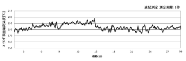
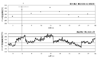
- the strand surface temperature was adjusted by measuring the strand surface temperature, displaying it on the display device as an image showing the temperature distribution, and monitoring it by the operator. Pellets were produced while the operator adjusted the liquid sprayers 3a to 3c and the air sprayers 6a to 6c from the set values so that the imaged strand surface temperature was within the set temperature range. A sample used in the above test method was cut with a strand cutter so that the pellet length was 3 mm, and the pellet immediately after being cut was collected in a paper bag.
- an average particle size of 1.2 ⁇ m are dry blended, and then a raw material is supplied under the conditions shown in Table 2 using a twin-screw extruder, followed by melt-kneading, followed by the pellet manufacturing apparatus shown in FIG. Was used to produce pellets. That is, a plurality of strands (strand diameter: 3 mm) were discharged from the discharge port of the melt-kneading apparatus. While conveying 15 strands at a rate of 50 m / min with a belt conveyor, the belt conveyor was continuously manufactured at room temperature (23 ° C.) for 3 hours to produce pellets.
- Examples 2 to 5 Pellets were produced in the same manner as in Example 1 and Comparative Example 1 except that the conditions shown in Tables 3 and 4 were used. Note that when the thermoplastic resin is amorphous, the melting point is read as the softening point.
Landscapes
- Engineering & Computer Science (AREA)
- Mechanical Engineering (AREA)
- Physics & Mathematics (AREA)
- Thermal Sciences (AREA)
- Processing And Handling Of Plastics And Other Materials For Molding In General (AREA)
Abstract
長時間の連続製造を行っても、連粒ペレットの発生や、ペレット切断面のヒゲや欠損の抑制および切粉の発生を抑え、ペレットの品質や生産性を向上する、熱可塑性樹脂のペレット製造方法、当該製造方法に有用なペレット製造装置を提供する。さらに詳しくは熱可塑性樹脂および添加材を含む組成物を溶融した後、供給機から吐出させることにより得られたストランドをベルトコンベアで搬送する工程と、該ベルトコンベア上のストランドに向けて液体を噴霧する工程と、該ベルトコンベア上のストランドに向けて気体を吹付ける工程と、ストランドの表面温度を測定する工程と、ベルトコンベアにより搬送されるストランドをペレット状に切断する工程とを有し、測定したストランドの表面温度に応じて、噴霧する液体量または液体温度を調整するペレットの製造方法および製造装置を提供する。
Description
本発明は、熱可塑性樹脂ペレットの製造装置およびその製造方法に関する。さらに詳しくは、混練機や押出機など(以下「供給機」という)で溶融させた熱可塑性樹脂または該熱可塑性樹脂を含む樹脂組成物を吐出することにより得られたストランドを冷却し、切断してペレット化するために使用するペレット製造装置およびペレット製造方法に関する。
一般に熱可塑性樹脂製品の製造工程は、樹脂原料とガラス繊維、難燃剤、離型剤、着色剤などの添加材を混ぜ合わせて混練し、造粒する一次工程と該一次工程で造粒されたペレットを射出成形機などに入れ、溶融して金型などで製品形状に成形する二次工程とからなる。
前述の一次工程において造粒されるペレットは粒の大きさや形状などが一定で均一であることが、次の二次工程での成形を効率よく行えるという観点から好ましく、一般的には単軸押出機や二軸押出機などの供給機出口に多数の細孔を有する口金を設置し、紐状のストランドを吐出させ、切断機で適当な長さに切断することによって、粒状のペレットを得ている。
このストランドを切断する方法としては、ストランドを水浴中で引取ながら冷却し、固化後水浴中から引き上げて切断機に導入して円筒状のペレットに切断する方法が通常用いられる。しかし、この方法では、供給機出口から吐出されたストランドの冷却が過剰となり、ストランドが硬く脆くなることがあるため、切断機に導入されるまでの間にしばしば切れてしまい、収率が低下するなどの問題があった。
そこで、熱可塑性樹脂を溶融した後、供給機から吐出させることにより得られたストランドを搬送するベルトコンベアと、該ベルトコンベア上のストランドに向けて水を噴霧する水噴霧装置と、付着水を除くための空気吹付け装置と、ベルトコンベアにより搬送されたストランドをペレット状に切断するストランドカッター装置を備えたペレット製造装置を用いて、ベルトコンベア上で搬送されているストランドに向けて水を噴霧した後、付着水を除くために空気を吹付け、得られたストランドをペレット状に切断するペレットの製造方法が知られている(特許文献1参照)。
前記特許文献1に記載の方法は、切断直後のペレットを採取して、その温度を測定せざるを得ず、ペレット温度の変化に対して、水の噴霧量およびエアー吹付け量の調整にタイムラグが生じざるを得なかった。このため長時間の連続製造を行った場合、例えば前段の溶融工程での安定性欠如や、外気の温度変化や、噴霧または空気吹付けの際の量や角度、水温または吹付ける空気温度の微妙な変化に起因して発生するストランドの温度変化に対処できず、ストランド温度が適切な温度制御範囲を超えて高温に、あるいは低温になりすぎることがあった。特に、スタートアップ時や再稼動時から数時間はストランド温度が安定せず、この傾向が顕著に現れていた。
ストランド温度が高温になりすぎると、溶融状態にあるストランド同士が融着して連粒ペレットが発生したり、ストランドの固化が不十分となり、ストランドカッターでのカッティングが困難となり、切断後のペレット形状が変形するなど品質低下をまねく傾向となり、一方、ストランド温度が低温になりすぎると、ストランドが硬く脆くなる結果、切断時ペレットを叩き割るような現象により欠損や切粉と呼ばれる微粉末状が発生したり、得られたペレットも切断面に欠損が生じやすくなり、同様に品質低下を招く傾向にあった。
そこで、本発明が解決しようとする課題は、長時間の連続製造を行っても、連粒ペレットの発生や、ペレット切断面のヒゲや欠損の抑制および切粉の発生を抑え、ペレットの品質や生産性を向上する、熱可塑性樹脂のペレット製造方法、当該製造方法に有用なペレット製造装置を提供することにある。
本発明者等は、上記の課題を解決するため鋭意研究を重ねた結果、搬送中のストランドそのものの温度管理を行うこと、すなわち、測定したストランドの表面温度に応じて、噴霧する液体量または液体温度を調整すること、さらには吹付ける気体量または気体温度を調整することにより、上記課題が解決できることを見出し、本発明を完成するに至った。
すなわち、本発明は、熱可塑性樹脂および添加材を含む組成物を溶融した後、供給機から吐出させることにより得られたストランドをベルトコンベアで搬送する工程と、該ベルトコンベア上のストランドに向けて液体を噴霧する工程と、該ベルトコンベア上のストランドに向けて気体を吹付ける工程と、ストランドの表面温度を測定する工程と、ベルトコンベアにより搬送されるストランドをペレット状に切断する工程とを有するペレットの製造方法であって、
測定したストランドの表面温度に応じて、噴霧する液体量または液体温度を調整することを特徴とするペレットの製造方法、に関する。
測定したストランドの表面温度に応じて、噴霧する液体量または液体温度を調整することを特徴とするペレットの製造方法、に関する。
また、本発明は、測定したストランドの表面温度に応じて、吹付ける気体量または気体温度を調整する前記記載のペレットの製造方法、に関する。
また、本発明は、熱可塑性樹脂および添加材を含む組成物を溶融した後、供給機から吐出させることにより得られたストランドを搬送するベルトコンベアと、該ベルトコンベアで搬送されるストランドに向けて液体を噴霧する液体噴霧装置と、該ベルトコンベアで搬送されるストランドに向けて気体を吹き付ける気体吹付け装置と、ストランドの表面温度の測定装置と、該ベルトコンベアで搬送されるストランドをペレット状に切断するストランドカッター装置を備え、ストランドの搬送方向に向かって、順に、前記液体噴霧装置と、前記気体吹付け装置と、前記ストランドカッター装置が配置されたペレット製造装置であって、ストランドの表面温度の測定装置が、前記ストランドカッター装置よりも前に位置すること、前記液体噴霧装置が、噴霧する液体量または液体温度の調整機構を有すること、を特徴とするペレット製造装置、に関する。
また、本発明は、前記気体吹付け装置が、吹付ける気体量または気体温度の調整機構を有する前記記載のペレット製造装置、に関する。
本発明によれば、長時間の連続製造を行っても、連粒ペレットの発生や、ペレット切断面のヒゲや欠損の抑制および切粉の発生を抑え、ペレットの品質や生産性を向上する熱可塑性樹脂のペレット製造方法、当該製造方法に有用なペレット製造装置を提供することができる。
本発明における熱可塑性樹脂組成物のペレット製造方法、および、当該製造方法に用いる本発明のペレット製造装置について説明する。ペレット製造装置は、ベルトコンベア、液体噴霧装置、気体吹付け装置、ストランドカッター装置、測定装置を備えている。
液体噴霧装置と、気体吹付け装置と、ストランドカッター装置は、ベルトコンベアによるストランドの搬送方向に向かって、順に配置されている。以下、ベルトコンベアと搬送工程、液体噴霧装置と液体噴霧工程、測定装置と表面温度測定工程、調整機構と冷却条件調整工程およびストランドカッター装置と切断工程について順次説明する。
液体噴霧装置と、気体吹付け装置と、ストランドカッター装置は、ベルトコンベアによるストランドの搬送方向に向かって、順に配置されている。以下、ベルトコンベアと搬送工程、液体噴霧装置と液体噴霧工程、測定装置と表面温度測定工程、調整機構と冷却条件調整工程およびストランドカッター装置と切断工程について順次説明する。
(1)熱可塑性樹脂および添加材を含む組成物を溶融した後、供給機から吐出させることにより得られたストランドをベルトコンベアで搬送する工程および当該ベルトコンベアについて説明する。
熱可塑性樹脂としては、一般的にストランドを経由してペレットとして製造されるすべての熱可塑性樹脂が挙げられ、たとえば、ポリエチレンやポリプロピレンなどのポリオレフィン樹脂及びその変性物、ポリエチレンテレフタレートやポリブチレンテレフタレートなどのポリエステル樹脂、ポリメチルメタクリレートやポリエチルメタクリレートなどの(メタ)アクリル樹脂、ポリスチレン、アクリロニトリル-ブタジエン-スチレン樹脂、アクリロニトリル-アクリルゴム-スチレン樹脂、アクリロニトリル-エチレンゴム-スチレン樹脂、(メタ)アクリル酸エステル-スチレン樹脂、スチレン-ブタジエン-スチレン樹脂などのスチレン樹脂、アイオノマー樹脂、ポリアクリルニトリル、6-ナイロン、6,6-ナイロン、6T-PA、9T-PA、MXD6-ナイロンなどのポリアミド樹脂、エチレン-酢酸ビニル樹脂、エチレン-アクリル酸樹脂、エチレン-エチルアクリレート樹脂、エチレン-ビニルアルコール樹脂、ポリ塩化ビニルやポリ塩化ビニリデンなどの塩素樹脂、ポリフッ化ビニルやポリフッ化ビニリデンなどのフッ素樹脂、ポリカーボネート樹脂、変性ポリフェニレンエーテル樹脂、メチルペンテン樹脂、セルロース樹脂等、ならびにオレフィン系エラストマー、グリシジル変性オレフィン系エラストマー、マレイン酸変性オレフィン系エラストマー、塩化ビニル系エラストマー、スチレン系エラストマー、ウレタン系エラストマー、ポリエステル系エラストマー、ポリアミド系エラストマー等の熱可塑性エラストマーなどが挙げられる。これらの熱可塑性樹脂は1種または2種以上を併用して用いることができる。さらに、いわゆるエンジニアリングプラスチックと呼ばれる融点が220℃以上の熱可塑性樹脂は、溶融温度から室温まで冷却される際の温度差が大きいことから、冷却される際の温度勾配が大きく、温度調整が非常に困難であることから、本発明の方法は特に好適に適用することができる。エンジニアリングプラスチックとしては、ポリブチレンテレフタレート、ナイロン9T、フッ素樹脂、ポリカーボネート樹脂、変性ポリアリーレンエーテル樹脂、ポリエーテルイミド樹脂、ポリエーテルエーテルケトン樹脂、熱可塑性ポリイミド樹脂などの熱可塑性樹脂が挙げられる。
本発明に用いる添加材としては、例えば、充填材、加水分解防止剤、着色剤、難燃剤、酸化防止剤、ポリエチレンワックス、酸化型ポリエチレンワックス、ポリプロピレンワックス、酸化型ポリプロピレンワックス、金属石鹸、スチレン系オリゴマー、ポリアミド系オリゴマー、重合開始剤、重合禁止剤、チタン系架橋剤、ジルコニア系架橋剤、その他の架橋剤、紫外線吸収剤、帯電防止剤、滑剤、離型剤、消泡剤、レベリング剤、光安定剤(例えば、ベンゾトリアゾール系、ヒンダードアミン等)、結晶核剤、キレート剤、イオン交換剤、分散剤、酸化防止剤、無機顔料、有機顔料、カップリング剤等をあげることができる。
本発明に用いることができる充填材としては、繊維状もしくは板状、鱗片状、粒状、不定形状および破砕品状など非繊維状の充填剤が挙げられる。具体的には、ガラス繊維、ガラスミルドファイバー、ガラスフラットファイバー、異形断面ガラスファイバー、ガラスカットファイバー、ステンレス繊維、アルミニウム繊維や黄銅繊維などの金属繊維、芳香族ポリアミド繊維やケブラーフィブリルなどの有機繊維、石膏繊維、セラミック繊維、アスベスト繊維、ジルコニア繊維、アルミナ繊維、シリカ繊維、酸化チタン繊維、炭化ケイ素繊維、Eガラス(板状・鱗片状・粒状・不定形状・破砕品)、Hガラス(板状・鱗片状・粒状・不定形状・破砕品)、Aガラス(板状・鱗片状・粒状・不定形状・破砕品)、Cガラス(板状・鱗片状・粒状・不定形状・破砕品)、天然石英ガラス(板状・鱗片状・粒状・不定形状・破砕品)、合成石英ガラス(板状・鱗片状・粒状・不定形状・破砕品)、ロックウール、アルミナ水和物(ウィスカー・板状)、チタン酸カリウムウィスカー、チタン酸バリウムウィスカー、ほう酸アルミニウムウィスカー、窒化ケイ素ウィスカー、タルク、カオリン、シリカ(破砕状・球状)、石英、炭酸カルシウム、炭酸亜鉛、マイカ、ガラスビーズ、ガラスフレーク、破砕状・不定形状ガラス、ガラスマイクロバルーン、クレー、二硫化モリブデン、ワラステナイト、酸化アルミニウム(破砕状)、透光性アルミナ(繊維状・板状・鱗片状・粒状・不定形状・破砕品)、酸化チタン(破砕状)、酸化亜鉛(繊維状・板状・鱗片状・粒状・不定形状・破砕品)などの金属酸化物、水酸化アルミニウム(繊維状・板状・鱗片状・粒状・不定形状・破砕品)などの金属水酸化物、窒化アルミニウム、透光性窒化アルミニウム(繊維状・板状・鱗片状・粒状・不定形状・破砕品)、ポリリン酸カルシウム、グラファイト、金属粉、金属フレーク、金属リボン、および金属酸化物などが挙げられる。
本発明に用いることができる 金属粉、金属フレークおよび金属リボンの金属種の具体例としては、銀、ニッケル、銅、亜鉛、アルミニウム、ステンレス、鉄、黄銅、クロムおよび錫などが例示される。また、無機充填材として、カーボン粉末、黒鉛、カーボンフレーク、鱗片状カーボン、カーボンナノチューブおよびPAN系やピッチ系の炭素繊維などの炭素系フィラーが挙げられ、これら充填材を2種類以上併用することも可能である。中でも、ガラス繊維、ガラスビーズ、ガラスフレークおよび炭酸カルシウムが好ましく用いられる。
本発明に用いることができるカップリング剤としては、シランカップリング剤、またはチタネートカップリング剤などが挙げられ、シランカップリング剤としては、例えば、ビニルトリメトキシシラン、ビニルトリエトキシシラン、2-(3,4-エポキシシクロヘキシル)エチルトリメトキシシラン、3-グリシドキシプロピルトリメトキシシラン、3-グリシドキシプロピルトリエトキシシラン、3-グリシドキシプロピルメチルジエトキシシラン、3-メタクリロキシプロピルメチルジメトキシシラン、3-メタクリロキシプロピルトリメトキシシラン、3-メタクリロキシプロピルメチルジエトキシシラン、3-メタクリロキシプロピルトリエトキシシラン、3-アクリロキシプロピルトリメトキシシラン、N-2-(アミノエチル)-3アミノプロピルメチルジメトキシシラン、N-2-(アミノエチル)-3アミノプロピルトリメトキシシラン、3-アミノプロプルトリメトキシシラン、3-アミノプロピルトリエトキシシラン、3-トリエトキシシリル-N-(1,3-ジメチル-ブチリデン)プロピルアミン、N-フェニル-3-アミノプロピルトリメトキシシラン、3-メルカプトプロピルトリメトキシシラン、ビス(トリエトキシシリルプロピル)テトラスルフィド、3-イソシアネートプロピルトリエトキシシランなどが挙げられる。また、チタネートカップリング剤としては、例えば、イソプロピルトリイソステアロイルチタネート、イソプロピルトリオクタノイルチタネート、イソプロピルトリ(ジオクチルパイロフォスフェート)チタネート、イソプロピルジメタクリルイソステアロイルチタネート、イソプロピルトリ(N,N-ジアミノエチル)チタネート、イソプロピルトリドデシルベンゼンスルホニルチタネート、イソプロピルイソステアロイルジアクリルチタネート、イソプロピルトリ(ジオクチルフォスフェート)チタネート、イソプロピルトリクミルフェニルチタネート、テトライソプロピルビス(ジオクチルフォスフェート)チタネート、テトラオクチルビス(ジトリデシルフォスフェート)チタネート、テトラ(2,2-ジアリルオキシメチル-1-ブチル)ビス(ジトリデシル)フォスフェートチタネート、ビス(ジオクチルパイロフォスフェート)オキシアセテートチタネート、ビス(ジオクチルパイロフォスフェート)エチレンチタネートなどが挙げられる。
本発明において熱可塑性樹脂に対する添加材の割合は、本発明の効果を損ねない範囲であれば、特に限定されるものではないが、熱可塑性樹脂100質量部に対して添加材0.01~1000質量部、好ましくは0.1~500質量部、より好ましくは0.5~200質量部、さらに好ましくは0.1~100質量部の範囲で、目的とする効果を発現するに十分な割合を配合して押出機等の供給機を用いて溶融混練すればよい。
熱可塑性樹脂および添加材を含む樹脂組成物の溶融は、公知の方法を制限無く用いることができ、たとえば、例えば、プラネタリミキサー、ディスパー、遊星型ミキサー、三本ロール、リボンブレンダー、ドラムタンブラー、ヘンシェルミキサー、バンバリーミキサー、単軸スクリュー押出機、二軸スクリュー押出機、加圧ニーダー、コニーダ、多軸スクリュー押出機等の供給機を用いて、樹脂温度が熱可塑性樹脂の融点以上になるよう加熱しながら混練する方法により行うことができる。
供給機の操作条件、例えば、バレル部の温度、スクリューの回転数、およびベントの有無などは、熱可塑性樹脂や充填剤、必要に応じて添加する添加剤の特性や押出量などによって適宜決められる。供給機の吐出部には、多数の孔を有する口金が設置されていて、該吐出部から前記熱可塑性樹脂と充填剤、必要に応じて添加する添加剤を配合して溶融混練して得られた熱可塑性樹脂組成物からなるストランドが吐出される。
吐出されるストランドの本数は特に制限は無く、1~100本の範囲であることが好ましく、さらに5~50本の範囲であることがより好ましく、さらに10~35本の範囲であることが特に好ましい。また、ストランドの直径は、本発明の効果を損ねない範囲で、特に制限されることないが、冷却能力を考慮した生産性の観点から0.5~10〔mm〕の範囲であることが好ましく、1~5〔mm〕の範囲であることがより好ましい。また、供給機からのストランドの押出速度は、本発明の効果を損ねなければ特に制限は無いが、通常、5~500m/分の範囲であることが好ましく、10m/分~100m/分の範囲であることがより好ましく、20~50m/分の範囲であることがさらに好ましい。
溶融した熱可塑性樹脂および添加材を含む樹脂組成物は、続いて供給機よりストランドとして吐出され、ベルトコンベアで搬送される。
ベルトコンベアの材質は金属または樹脂が挙げられる。ベルトコンベアの材質が金属である場合、液体噴霧装置から噴霧される液体などにより腐食や錆びが発生しにくい材質、たとえばステンレス鋼や、チタン、ジルコニウムなどを含む合金を用いることが好ましい。また、金属を用いる場合、気体吹付け工程において気体がベルトコンベア中を通過できることで、気体の跳ね返り等、気流の乱れに起因するストランドの乱れを抑制することができるうえ、吹付ける気体による押さえ込みができることでストランドの搬送性も向上するため、金属メッシュ形状とすることが好ましい。金属メッシュの目開きや種類は特に限定されないが、目開きがストランドの太さよりも小さいものが好ましい。金属メッシュは、金属線を織り込む事により製作されたものを用いても、パンチングメタル製のものを用いてもよい。金属線により織り込まれた金属メッシュは屈曲性もよく回転性に優れるためより好ましい。
一方、ベルトコンベアの材質が樹脂である場合、例えば、ポリエステル樹脂、ポリオレフィン樹脂、ポリイミド樹脂、ポリアミド樹脂、アラミド樹脂、ポイアミドイミド樹脂、ポリウレタン樹脂、フッ素樹脂、シリコーン樹脂およびその他の各種ゴム系樹脂などが挙げられる。
ベルトコンベアがストランドを搬送する速度としては、本発明の効果を損ねなければ特に制限は無いが、通常、供給機からのストランドの押出速度と同じであることが好ましい。
ベルトコンベアの角度は、本発明の効果を損ねなければ特に限定されないが、ストランドより除かれた冷却用の液体が、ストランドカッター方向へ流れこむことを抑制しつつ、かつ、ストランドの搬送性に優れる観点から、さらには、吐出口とストランドカッターの高さ調整も兼ねて、進行方向に対して上向きに0~20°であることが好ましく、0°より高い角度から3°までの角度であることが更に好ましい。上向きに0°より高い角度を付しておくことで、噴霧された液体を回収しやすくできる。
(2)ベルトコンベア上のストランドに向けて液体を噴霧する工程および液体噴霧装置について説明する。
次に、本発明は、ストランド表面に液体を付着させ、ストランドと液体との熱交換および液体の気化熱によりストランドを冷却するために、ベルトコンベア上のストランドに向けて液体を噴霧する工程を有する。液体の噴霧は液体噴霧装置を用いて行い、該ベルトコンベア上のストランドに液体を噴霧可能な位置にボルト等で固定された噴霧ノズルから行う。当該液体噴霧装置は、冷却用の液体を噴霧できる装置であれば公知のものでよい。噴霧面は、たとえば円状、楕円状、直線状、四角形状になるものが挙げられる。噴霧ノズルからストランド(噴霧面)までの距離は特に制限されないが、10~1000mmの範囲であることが好ましく、50~500mmの範囲であることがより好ましく、100mm~250mmの範囲であることがさらに好ましい。ベルトコンベア上で複数のストランドが搬送される場合、ストランドにおける噴霧面を調整することで、各ストランドの表面温度が均一になるよう噴霧することが好ましい。各ストランドの間で表面温度に差がありすぎると、均質なペレットが得られず、ストランド切れやペレット切断面の欠損またはヒゲが発生する傾向となるためである。図1では一定間隔で3機の液体噴霧装置が設置されているが、本発明はこれに限定されず、1~10機の範囲で適宜調整することが好ましい。液体噴霧装置から噴霧される液体としては、水や、アルコール、エチレングリコール、アセトンなどの有機溶媒、蟻酸、酢酸などの酸が挙げられるが、生産性の面から水が好ましい。また、液体噴霧装置から噴霧される液体の温度(以下、液体温度)は、室温(季節や場所により異なるがおおむね平均して15~23℃の範囲である)であることが好ましい。ただし、噴霧する液体温度を調整する場合、室温に対して、1~50℃の範囲で異なる液温のものを組合せて用いることもできる。
該液体噴霧装置は、単位時間当たりの液体の噴霧量が、ストランド1本当たり、0.1~50ml/分の範囲であることが好ましく、さらに1~10ml/分の範囲であることがより好ましい。
該液体噴霧装置は、噴霧する液体量または液体温度の調整機構(液冷調整機構)を有する。前記液体噴霧装置において噴霧する液体量の調整機構としては、前記液体噴霧装置の噴霧ノズルに連通する配管に流す液体の流量や圧力を調節するバルブや弁など公知のものが挙げられる。調節する際は、手動で調節する機構か、電動で調節する場合は、電磁弁やモーター等を用いて連続ないし段階的に調節できる機構が備えられていても良い。また、噴霧する液体温度の調整機構としては、少なくとも2つの異なる温度の液体タンクを液体噴霧装置内または同装置外に備えておき、所望の設定温度となるよう、それぞれの流量を例えば比例弁を用いて調整する方法や外部より電気、蒸気等の熱源を供給し、熱交換器等に流入するそれら熱源の流量を調整することにより、所望の温度に調整された液体を噴霧ノズルより噴霧することができる。また、液体噴霧装置または噴霧ノズルをストランドの搬送方向に沿って複数個用いてよい場合は、それぞれの液体噴霧装置ないし噴霧ノズルから噴霧される液体温度がそれぞれ異なるように設定しておき、各液体噴霧装置ないし噴霧ノズルから噴霧される液体量を調節することにより、ストランドが所望の設定温度となるよう調整しながら噴霧しても良い。同様に、液体噴霧装置または噴霧ノズルを複数個用いてよい場合は、それぞれの液体噴霧装置ないし噴霧ノズルから噴霧される液体量を独立して調整可能としておき、ストランドが所望の設定温度となるように各液体噴霧装置ないし噴霧ノズルから噴霧される液体量を調整してもよい。さらに、液体噴霧装置または噴霧ノズルを複数個用いて良い場合は、上流側の液体量を多くするか、あるいは液体温度を低くし、下流側の液体量を上流側より少なくするか、あるいは液体温度を上流側より高くしてもよい。この場合には、上流側の液体噴霧装置または噴霧ノズルによる液体噴霧でストランドを急冷し、下流側の液体噴霧装置または噴霧ノズルによる液体噴霧でストランドを徐冷することが可能になり、液体噴霧後のストランドの表面温度をより高精度に管理することが可能になる。
噴霧ノズルの噴霧角度としては、一つの噴霧ノズルによりベルトコンベアの幅方向全体に液体を噴霧する場合には、ベルトコンベアの幅とベルトコンベアと噴霧ノズルとの距離に応じて噴霧ノズルの噴霧角度を選択する。複数の噴霧ノズルによりベルトコンベアの幅方向全体に液体を噴霧する場合には、ベルトコンベア上における噴霧面が離間するとストランドに液体が噴霧されない箇所が生じ、ベルトコンベア上における噴霧面が重複すると両方の噴霧ノズルから液体が噴霧されるストランドが生じる可能性がある。そのため、ベルトコンベア上における噴霧面が接するように複数の噴霧ノズルを配置することがベルトコンベアの幅方向でストランドに対する冷却特性を均一化するために好ましい。噴霧面の形状が非円形である場合には、鉛直方向と平行な軸線回りに回転可能に噴霧ノズルを設置し、ベルトコンベアの幅方向で隣り合う噴霧面が接するように噴霧ノズルを回転させることにより、ストランドに対する冷却特性を均一化することができる。ベルトコンベアの幅方向に液体噴霧装置または噴霧ノズルを複数配置する場合には、複数のストランドのそれぞれに対応して設けてもよいし、一部のストランドによって群を形成し、群毎に設ける構成としてもよい。いずれの場合も液体噴霧装置または噴霧ノズルの液体噴霧を独立して調整可能とすることにより、各ストランドの表面温度あるいは各ストランド群の表面温度に応じた最適な噴霧冷却を実施することができる。
「供給機の吐出口から吐出されたストランドが液体噴霧装置より噴霧される液体と最初に接触するまでの距離」(L1)は、特に限定されないが、ストランドのベルトコンベア上での滑りの抑制と、ストランド同士の融着を抑制する観点から10~1000mmの範囲であることが好ましく、50~500mmの範囲であることがさらに好ましい。
また、「供給機の吐出口から吐出されたストランドが液体噴霧装置より噴霧される液体と最後に接触した距離」から「供給機の吐出口から吐出されたストランドが液体噴霧装置より噴霧される液体と最初に接触するまでの距離」を差し引いた距離(L2)は、ストランドに十分に液体を噴霧できるよう500~2000mmの範囲であることが好ましく、さらに1000~1500mmの範囲であることがより好ましい。
なお、噴霧された液体は回収され、フィルターで浄化等を施した後、例えば、噴霧用途に再利用することができる。
(3)該ベルトコンベア上のストランドに向けて気体を吹付ける工程および気体吹付け装置について説明する。
次に、本発明は、ストランド表面に付着した液体を除去するため、ベルトコンベア上のストランドに向けて気体を吹付ける工程を有する。気体の吹付けは、該ベルトコンベア上のストランドに気体を吹付け可能な位置にボルト等で固定された気体吹付け装置を用いて行う。該気体吹付け装置は、ストランドに付着した液体があればストランド表面から取り除くと共に、ストランドを空冷するための装置であり、公知のエアブロー装置やドライヤー装置を用いることができ、吹付ける気体量または気体温度の調整機構(空冷調整機構)として、風量調節機構や、ヒーターや冷却装置が組み込まれており、気体の温度調節が可能な公知の気体吹付け装置を用いることもできる。気体吹付け装置を複数用いてよい場合や、気体吹付け装置が複数の吹出し口を備えていても良い場合は、吹きつけられる気体温度がそれぞれの装置毎または吹出し口毎に異なるように設定しておき、各気体吹付け装置ないし吹出し口から吹きつけられる気体量を調節しながら、ストランドが所望の設定温度となるよう調整しながら気体を吹付けても良い。同様に、気体吹付け装置または吹出し口を複数用いてよい場合は、それぞれの装置ないし吹出し口から吹きつけられる気体量を独立して調整可能としておき、ストランドが所望の設定温度となるように各装置ないし吹出し口から吹きつけられる気体量を調整してもよい。さらに、気体吹付け装置ないし吹出し口を複数用いて良い場合は、上流側の気体量を多くするか、あるいは気体温度を低くし、下流側の気体量を上流側より少なくするか、あるいは気体温度を上流側より高くしてもよい。この場合には、上流側の気体吹付け装置ないし吹出し口による気体吹付けでストランドを急冷し、下流側の気体吹付け装置ないし吹出し口による気体吹付けでストランドを徐冷することが可能になり、気体吹付け後のストランドの表面温度をより高精度に管理することが可能になる。
気体の吹付け角度としては、ストランド表面に付着した液体を除去するためには、特に限定されないが、上方から下方へ気体を吹付ける装置であることが好ましい。吹付け面は、たとえば円状、楕円状、直線状、四角形状になるものが挙げられる。吹付け冷却を考慮した場合の気体の吹付け角度としては、一つの吹出し口によりベルトコンベアの幅方向全体に気体を吹付ける場合には、ベルトコンベアの幅とベルトコンベアと吹出し口との距離応じて吹付け角度を選択する。複数の吹出し口によりベルトコンベアの幅方向全体に気体を噴霧する場合には、ベルトコンベア上における吹付け面が離間するとストランドに気体が吹付けられない箇所が生じ、ベルトコンベア上における吹付け面が重複すると両方の吹出し口から気体が吹き付けられるストランドが生じる可能性がある。そのため、ベルトコンベア上における吹付け面が接するように複数の吹出し口を配置することがベルトコンベアの幅方向でストランドに対する冷却特性を均一化するために好ましい。吹付け面の形状が非円形である場合には、鉛直方向と平行な軸線回りに回転可能に吹出し口を設置し、ベルトコンベアの幅方向で隣り合う吹付け面が接するように吹出し口を回転させることにより、ストランドに対する冷却特性を均一化することができる。ベルトコンベアの幅方向に気体吹付け装置ないし吹出し口を複数配置する場合には、複数のストランドのそれぞれに対応して設けてもよいし、一部のストランドによって群を形成し、群毎に設ける構成としてもよい。いずれの場合も気体吹付け装置ないし吹出し口の気体吹付けを独立して調整可能とすることにより、各ストランドの表面温度あるいは各ストランド群の表面温度に応じた最適な吹付け冷却を実施することができる。
複数のストランドが搬送される場合、吹付け面を調整することで、各ストランドの表面温度がより均一になるよう吹付けながら、表面に付着している液体を除くことが好ましい。各ストランドの表面温度に差がありすぎると、均質なペレットが得られず、ストランド切れやペレット切断面の欠損または切粉が発生する傾向となるためである。図1では一定間隔で3機の気体吹付け装置が設置されているが、本発明はこれに限定されず、1~10機の範囲で適宜調整することが好ましい。吹付ける気体の風速、風量はストランドの温度を所定範囲内に調整可能、且つ、ストランド表面に付着した液体を除去可能であれば特に限定されないが、ストランドがベルトコンベア上で蛇行しない風速、風量であることが好ましい。吹付ける気体としては、窒素、アルゴンなどの不活性ガス存在下の気体であってもよいが、生産性の観点から空気(エアー)であることが好ましい。また、気体吹付け装置から吹付けられる気体の温度は、ストランドの温度を所定範囲内に調整可能、且つ、ストランド表面に付着した液体を除去可能であれば特に限定する必要はないものの、(室温-30℃)~(室温+30℃)の範囲であることが好ましく、(室温-15℃)~(室温+15℃)の範囲であることがより好ましい。
当該気体吹付け装置は、単位時間当たりの気体の吹付け量が、ストランド1本当たり、0.1~5リットル/秒の範囲であることが好ましく、0.3~1.5リットル/秒の範囲であることがより好ましい。
「供給機の吐出口から吐出されたストランドが気体吹付け装置より吹付けられる気体と最初に接触した距離」から「供給機の吐出口から吐出されたストランドが液体噴霧装置より噴霧される液体と最後に接触した距離」を差し引いた距離(L3)は、吹付け気体が液体の噴霧に影響を及ぼさないよう200~600mmの範囲であることが好ましく、さらに200~500mmの範囲であることがより好ましい。
「供給機の吐出口から吐出されたストランドが気体吹付け装置より吹付けられる気体と最後に接触した距離」から、「該吐出口から吐出されたストランドが気体吹付け装置より吹付けられる気体と最初に接触した距離」を差し引いた距離(L4)は、吹き付ける気体同士の干渉防止の観点から200~2000mmの範囲であることが好ましく、さらに500~1500mmの範囲であることがより好ましい。
一方、「供給機の吐出口からストランドカッターまでの距離」から「供給機の吐出口から吐出されたストランドが気体吹付け装置より吹付けられる気体と最後に接触した距離」を差し引いた距離(L5)は、温度安定化、ストランド搬送トラブル等の対処(スタートアップ時やストランド切れの際、ストランドをカッターに投入する為の作業スペース)、ストランド表面温度測定のためのスペース確保の観点から500~2000mmの範囲であることが好ましく、さらに800~1500mmの範囲であることがより好ましい。
(4)ストランドの表面温度を測定する工程およびストランドの表面温度の測定装置について説明する。
続いて、本発明は、ストランドの表面温度を測定する工程を有する。ストランドの表面温度の測定装置は、前記ストランドカッター装置よりも前(ストランド搬送方向の上流側)に位置すればよく、前記液体噴霧装置と前記気体吹付け装置との間に配置されるか、前記気体吹付け装置と前記ストランドカッター装置との間に配置されるか、または、前記液体噴霧装置と前記気体吹付け装置との間および前記気体吹付け装置と前記ストランドカッター装置との間の両方に配置されていてもよい。このうち、ストランドの表面温度の測定装置は、ストランドカッター装置の直前にあるストランドの表面温度が測定できることが好ましく、その好ましい設置位置はストランドの搬送速度にもよるため一概には規定できないものの、ストランドカッター装置から0.1~100mmの範囲の距離にあるストランドの表面温度を測定できることが好ましく、さらに1~50mmの範囲の距離にあるストランドの表面温度を測定できることがより好ましい。なお、ストランドが複数本の場合、複数のストランドを同時に測定することが好ましく、そのように測定できれば測定装置の設置場所は特に限定されない。
ストランドの表面温度の測定装置は、ストランド表面から発生する赤外線を非接触で測定して、温度を測定できるものであれば公知のものでかまわない。
本発明では、測定したストランドの表面温度、特に複数ある場合は、(a)各ストランドの表面温度の最高温度の中で最も高い温度、(b)各ストランドの表面温度の最高温度の中で最も低い温度、または(c)各ストランドの表面温度の最高温度の平均温度、に応じて、噴霧する液体量もしくは液体温度を調整したり、吹付ける気体量もしくは気体温度を調整したり、または、その両方の調整を適宜行えば良い。特に、(a)と(b)を組合せて、さらには、(a)と(b)の差が小さくなるように、当該調整を行うことが好ましい。
噴霧する液体量もしくは液体温度の調整および/または吹付ける気体量もしくは気体温度の調整は、好ましくは測定したストランドの表面温度の最高温度、特に複数ある場合は、(a)の場合は、当該最も高い温度、(b)の場合は、当該最も低い温度、(c)の場合は、当該平均温度が、予め熱可塑性樹脂の種類に応じて定めた設定温度範囲を超えた場合に、行うことが好ましい。
予め熱可塑性樹脂の種類に応じて定めた設定温度範囲は、別途、ストランドの表面温度に応じたストランドの状況(ストランド切れやストランド融着の状況)、ペレットの品質(連粒ペレットの発生や、ペレット形状や欠損、ヒゲ等の発生の状況)、切粉の発生状況を評価する実験等を行い、適宜設定すればよいが、例えば、以下の表1に記載した範囲を例示できる。

ただし、測定装置を気体吹付け装置とストランドカッター装置との間にのみ配置する場合には、測定装置によるストランドの表面温度測定が行われる位置は、液体噴霧位置および気体吹付け位置よりも下流側であるため、しきい値を超えた表面温度を測定した後に、少なくとも気体吹付け位置と測定位置との間のストランドに対する冷却調整を実施することができない。そのため、高温側しきい値および低温側しきい値の設定は、気体吹付けによる冷却調整を行う場合は、気体吹付け位置から測定位置まで搬送される間のストランドの温度変化、気体吹付けによる冷却調整を行わない場合は、液体噴霧位置から測定位置まで搬送される間のストランドの温度変化を見込んで行うことが好ましい。
また、ストランドの表面温度が高温側しきい値を上回った場合と、低温側しきい値を下回った場合とを比較すると、低温側しきい値を下回った場合の方が生産性低下と品質不良の度合いが大きいことから、ストランドの表面温度を測定した結果に、高温側しきい値を上回る表面温度と、低温側しきい値を下回る表面温度の両方が含まれている場合には、低温側しきい値を下回った場合の冷却調整を優先して実施することが好ましい。このことから(b)各ストランドの表面温度の最高温度の最も低い温度に応じて、噴霧する液体量もしくは液体温度を調整したり、吹付ける気体量もしくは気体温度を調整することが好ましい。
液体噴霧装置によるストランドの冷却は、噴霧する液体量と液体温度の少なくとも一方を調整することにより行われる。上述した噴霧される液体の液体温度によるストランド冷却、あるいは噴霧される液体の液体量によるストランドの冷却(適宜、噴霧冷却と総称する)については、噴霧冷却条件と、ストランドに対する冷却特性との相関関係を予め実験やシミュレーションにより求めておき、例えば、オペレーター等が適宜調整すれば良い。また、液体噴霧装置または噴霧ノズルをストランドの搬送方向に沿って複数個用いる場合には、それぞれの噴霧冷却条件と、ストランドに対する冷却特性との相関関係に加えて、複数の液体噴霧装置または噴霧ノズルの組み合わせの全てについて噴霧冷却条件と、ストランドに対する冷却特性との相関関係を求めておき、例えば、オペレーター等が適宜調整すれば良い。
気体吹付け装置によるストランドの冷却は、吹付ける気体量または気体温度を調整することにより行われる。上述した吹付けられる気体の気体温度によるストランド冷却、あるいは吹付けられる気体量によるストランドの冷却(適宜、吹付け冷却と総称する)については、吹付け冷却条件と、ストランドに対する冷却特性との相関関係を予め実験やシミュレーションにより求めておき、例えば、オペレーター等が適宜調整すれば良い。また、気体吹付け装置ないし吹出し口をストランドの搬送方向に沿って複数用いる場合には、それぞれの吹付け冷却条件と、ストランドに対する冷却特性との相関関係に加えて、複数の気体吹付け装置ないし吹出し口の組み合わせの全てについて吹付け冷却条件と、ストランドに対する冷却特性との相関関係を求めておき、例えば、オペレーター等が適宜調整すれば良い。
また、噴霧冷却と吹付け冷却とを組み合わせて冷却調整を実行する場合には、各冷却における冷却条件と、ストランドに対する冷却特性との相関関係に加えて、両方の冷却を実施したときのストランドに対する冷却特性との相関関係を求めておき、例えば、オペレーター等が適宜調整すれば良い。ストランドの搬送方向に沿った複数個の液体噴霧装置または噴霧ノズル、複数個の気体吹付け装置ないし吹出し口を用いる場合には、それぞれの複数の液体噴霧装置または噴霧ノズル、複数の気体吹付け装置ないし吹出し口の組み合わせの全てについて、冷却条件と、ストランドに対する冷却特性との相関関係を求めておき、例えば、オペレーター等が適宜調整すれば良い。
測定装置を液体噴霧装置と気体吹付け装置との間にのみ配置する場合には、気体吹付け装置による気体の吹付けに伴うストランドの温度低下およびストランドカッター装置までの搬送に伴うストランドの温度低下を予め求めておくことが好ましい。そして、測定装置により測定されるストランドの表面温度に係る設定温度範囲のしきい値については、上記の温度低下を見込んだ値に設定することが好ましい。調整機構は、液体噴霧装置と気体吹付け装置との間におけるストランドの表面温度が設定温度範囲に入るべく噴霧冷却の冷却条件を調整することが好ましい。
測定装置を液体噴霧装置と気体吹付け装置との間、気体吹付け装置とストランドカッター装置との間の両方に配置する場合には、上記測定装置を液体噴霧装置と気体吹付け装置との間にのみ配置する場合と同様に、液体噴霧装置と気体吹付け装置との間に配置された測定装置で測定されるストランドの表面温度に係る設定温度範囲のしきい値を設定し、当該設定温度範囲にストランドの表面温度が入るべく噴霧冷却の冷却条件を調整することが好ましい。また、気体吹付け装置とストランドカッター装置との間に配置された測定装置で測定されるストランドの表面温度に係る設定温度範囲のしきい値を設定し、当該設定温度範囲にストランドの表面温度が入るべく噴霧冷却と吹付け冷却の少なくとも一方の冷却条件を調整することもできる。
本実施形態のペレット製造装置においては、ストランドの表面温度の測定装置から得られたストランド表面温度情報を表示する装置、または、設定温度の範囲を超えた際に、アラーム等を発する装置を備えていることが好ましい。前記表示装置やアラーム等を発する装置は、前記測定装置と一体であっても良いし、ケーブル等を介して、前記測定装置とは別の装置としても良い。
(5)ベルトコンベアにより搬送されるストランドをペレット状に切断する工程およびストランドカッター装置について
ストランドカッターは紐状のストランド群を適切な長さに切断し、ペレットにする装置である、公知のさまざまな方法を使用可能であり、例えば回転刃と固定刃とを有するものが挙げられる。ストランドカッターで切断して得られたペレットは、落差ないし高低差を利用して搬送され、冷却及びペレット表面に付着した切粉を除くため、振動装置や気体吹付け装置など公知の後処理工程を施すこともできる。
ペレット長は特に制限されないが、0.5~10mmの範囲であることが好ましく、1~5mmの範囲であることがより好ましい。
ペレット長は特に制限されないが、0.5~10mmの範囲であることが好ましく、1~5mmの範囲であることがより好ましい。
(6)その他
本発明の製造方法を用いて得られたペレットは、射出成形、押出成形、ブロー成形、トランスファー成形など各種成形に供することが可能であるが、多量の粉末による計量不良が課題であった射出成形用途に適している。また、射出成形や押出成形、ブロー成形、トランスファー成形などを経て様々な用途に使用可能である。例えば、センサー、LEDランプ、コネクター、ソケット、抵抗器、リレーケース、スイッチ、コイルボビン、コンデンサー、バリコンケース、発振子、各種端子板、変成器、プラグ、プリント基板、チューナー、スピーカー、マイクロフォン、ヘッドフォン、小型モーター、磁気ヘッドベース、半導体、液晶、FDDキャリッジ、FDDシャーシ、モーターブラッシュホルダー、パラボラアンテナ、コンピューター関連部品などに代表される電気・電子部品;VTR部品、テレビ部品、アイロン、ヘアードライヤー、炊飯器部品、電子レンジ部品、音響部品、オーディオ・レーザーディスク(登録商標)・コンパクトディスクなどの音声機器部品、照明部品、冷蔵庫部品、エアコン部品、タイプライター部品、ワードプロセッサー部品などに代表される家庭、事務電気製品部品;オフィスコンピューター関連部品、電話器関連部品、ファクシミリ関連部品、複写機関連部品、洗浄用治具、モーター部品、ライター、タイプライターなどに代表される機械関連部品:顕微鏡、双眼鏡、カメラ、時計などに代表される光学機器、精密機械関連部品;水道蛇口コマ、混合水栓、混合弁、ポンプ部品、パイプジョイント、継手類(エルボ、チーズ、ソケットなど)、水量調節弁、減圧弁、逃がし弁、電磁弁、三方弁、サーモバルブ、湯温センサー、水量センサー、浴槽用アダプタ、水道メーターハウジングなどの水廻り部品;バルブオルタネーターターミナル、オルタネーターコネクター,ICレギュレーター、ライトディヤー用ポテンシオメーターベース、排気ガスバルブなどの各種バルブ、燃料関係・排気系・吸気系各種パイプ、エアーインテークノズルスノーケル、インテークマニホールド、燃料ポンプ、エンジン冷却水ジョイント、キャブレターメインボディー、キャブレタースペーサー、排気ガスセンサー、冷却水センサー、油温センサー、スロットルポジションセンサー、クランクシャフトポジションセンサー、エアーフローメーター、ブレーキパッド摩耗センサー、エアコン用サーモスタットベース、暖房温風フローコントロールバルブ、ラジエーターモーター用ブラッシュホルダー、ウォーターポンプインペラー、タービンベイン、ワイパーモーター関係部品、デュストリビューター、スタータースイッチ、スターターリレー、トランスミッション用ワイヤーハーネス、ウィンドウォッシャーノズル、エアコンパネルスイッチ基板、燃料関係電磁気弁用コイル、ヒューズ用コネクター、ホーンターミナル、電装部品絶縁板、ステップモーターローター、ランプソケット、ランプリフレクター、ランプハウジング、ブレーキピストン、ソレノイドボビン、エンジンオイルフィルター、点火装置ケース、車速センサー、およびケーブルライナーなどの自動車・車両関連部品など各種用途が例示できる。
本発明の製造方法を用いて得られたペレットは、射出成形、押出成形、ブロー成形、トランスファー成形など各種成形に供することが可能であるが、多量の粉末による計量不良が課題であった射出成形用途に適している。また、射出成形や押出成形、ブロー成形、トランスファー成形などを経て様々な用途に使用可能である。例えば、センサー、LEDランプ、コネクター、ソケット、抵抗器、リレーケース、スイッチ、コイルボビン、コンデンサー、バリコンケース、発振子、各種端子板、変成器、プラグ、プリント基板、チューナー、スピーカー、マイクロフォン、ヘッドフォン、小型モーター、磁気ヘッドベース、半導体、液晶、FDDキャリッジ、FDDシャーシ、モーターブラッシュホルダー、パラボラアンテナ、コンピューター関連部品などに代表される電気・電子部品;VTR部品、テレビ部品、アイロン、ヘアードライヤー、炊飯器部品、電子レンジ部品、音響部品、オーディオ・レーザーディスク(登録商標)・コンパクトディスクなどの音声機器部品、照明部品、冷蔵庫部品、エアコン部品、タイプライター部品、ワードプロセッサー部品などに代表される家庭、事務電気製品部品;オフィスコンピューター関連部品、電話器関連部品、ファクシミリ関連部品、複写機関連部品、洗浄用治具、モーター部品、ライター、タイプライターなどに代表される機械関連部品:顕微鏡、双眼鏡、カメラ、時計などに代表される光学機器、精密機械関連部品;水道蛇口コマ、混合水栓、混合弁、ポンプ部品、パイプジョイント、継手類(エルボ、チーズ、ソケットなど)、水量調節弁、減圧弁、逃がし弁、電磁弁、三方弁、サーモバルブ、湯温センサー、水量センサー、浴槽用アダプタ、水道メーターハウジングなどの水廻り部品;バルブオルタネーターターミナル、オルタネーターコネクター,ICレギュレーター、ライトディヤー用ポテンシオメーターベース、排気ガスバルブなどの各種バルブ、燃料関係・排気系・吸気系各種パイプ、エアーインテークノズルスノーケル、インテークマニホールド、燃料ポンプ、エンジン冷却水ジョイント、キャブレターメインボディー、キャブレタースペーサー、排気ガスセンサー、冷却水センサー、油温センサー、スロットルポジションセンサー、クランクシャフトポジションセンサー、エアーフローメーター、ブレーキパッド摩耗センサー、エアコン用サーモスタットベース、暖房温風フローコントロールバルブ、ラジエーターモーター用ブラッシュホルダー、ウォーターポンプインペラー、タービンベイン、ワイパーモーター関係部品、デュストリビューター、スタータースイッチ、スターターリレー、トランスミッション用ワイヤーハーネス、ウィンドウォッシャーノズル、エアコンパネルスイッチ基板、燃料関係電磁気弁用コイル、ヒューズ用コネクター、ホーンターミナル、電装部品絶縁板、ステップモーターローター、ランプソケット、ランプリフレクター、ランプハウジング、ブレーキピストン、ソレノイドボビン、エンジンオイルフィルター、点火装置ケース、車速センサー、およびケーブルライナーなどの自動車・車両関連部品など各種用途が例示できる。
以下、本発明を実施例に基づきさらに詳細に説明するが、本発明はこれに限定されるものではない。
(ペレット製造装置)
図1を用いて本発明の実施例で用いた製造装置を説明する。まず、熱可塑性樹脂を溶融するための供給機1(株式会社日本製鋼所製二軸押出機「TEX-26」)の先端にストランド15本が吐出されるよう吐出口2を取り付けた。続いて、吐出されたストランドを搬送するためのベルトコンベア8(ストランドとの接触面はヘリンボン織ステンレス鋼メッシュ)を設置し、ベルトコンベア搬送面の上部に、ベルトコンベアで搬送されるストランドを冷却するための、3機の液体噴霧装置3a~3cがベルトコンベア搬送方向に沿って等間隔で、ベルトコンベアから170mmの高さで並べ、続いて、3機の気体吹付け装置6a~6cがベルトコンベア搬送方向に沿って等間隔で、ベルトコンベアから100mmの高さで配置され、さらに、冷却されたストランドの表面温度を測定するための赤外線温度計(アピステ株式会社製「FSV-2000」)をベルトコンベアから800mmの高さにボルトで固定し設置した。前記液体噴霧装置は、20℃冷却水を噴霧できる装置であって、噴霧面が直線状となる噴霧ノズルを備え、かつ、噴霧ノズルに連通する配管に噴霧量調整用バルブが備えられているものを用いた。また、気体吹付け装置は、吹付け面が直線状となる吹付け口を備えたエアーブロワーを用いた。
図1を用いて本発明の実施例で用いた製造装置を説明する。まず、熱可塑性樹脂を溶融するための供給機1(株式会社日本製鋼所製二軸押出機「TEX-26」)の先端にストランド15本が吐出されるよう吐出口2を取り付けた。続いて、吐出されたストランドを搬送するためのベルトコンベア8(ストランドとの接触面はヘリンボン織ステンレス鋼メッシュ)を設置し、ベルトコンベア搬送面の上部に、ベルトコンベアで搬送されるストランドを冷却するための、3機の液体噴霧装置3a~3cがベルトコンベア搬送方向に沿って等間隔で、ベルトコンベアから170mmの高さで並べ、続いて、3機の気体吹付け装置6a~6cがベルトコンベア搬送方向に沿って等間隔で、ベルトコンベアから100mmの高さで配置され、さらに、冷却されたストランドの表面温度を測定するための赤外線温度計(アピステ株式会社製「FSV-2000」)をベルトコンベアから800mmの高さにボルトで固定し設置した。前記液体噴霧装置は、20℃冷却水を噴霧できる装置であって、噴霧面が直線状となる噴霧ノズルを備え、かつ、噴霧ノズルに連通する配管に噴霧量調整用バルブが備えられているものを用いた。また、気体吹付け装置は、吹付け面が直線状となる吹付け口を備えたエアーブロワーを用いた。
続いて、ベルトコンベアに隣接して、ベルトコンベアで搬送されたストランドがペレット化されるためのストランドカッター9を設置した。
(試験例1) ストランドカッター直後の粉末量
ストランドカッターを通過したペレットを0.5kg採取し、目開き2mm、直径300mm、深さ50mmの円形篩を用いて篩にかけて取り除かれた粉末量を計量し、採取したペレット(0.5kg)に対する質量割合(ppm)として算出した。
ストランドカッターを通過したペレットを0.5kg採取し、目開き2mm、直径300mm、深さ50mmの円形篩を用いて篩にかけて取り除かれた粉末量を計量し、採取したペレット(0.5kg)に対する質量割合(ppm)として算出した。
(試験例2)ペレット形状(欠損、ヒゲの観察)
ストランドカッターで切断したペレットを採取して、目視でペレットの表面観測(欠損、ヒゲの観察)を行った。より具体的には、ストランドカッターで切断されたペレット約10kgを採取した紙袋から、無作為に50個のペレットを抜き取り、目視にてペレットの欠損またはヒゲの有無を観察した。ペレットに1箇所以上の欠損またはヒゲがある個数を調べ、以下の基準に沿って評価した。なお、ペレットの切断面写真(2次元情報)を元に、1箇所の欠損またはヒゲあたりの面積が、断面積の5%以上の場合に、「欠損」または「ヒゲ」としてカウントするものとした。
◎ 1~ 9個
○ 10~19個
△ 20~29個
× 30個以上
ストランドカッターで切断したペレットを採取して、目視でペレットの表面観測(欠損、ヒゲの観察)を行った。より具体的には、ストランドカッターで切断されたペレット約10kgを採取した紙袋から、無作為に50個のペレットを抜き取り、目視にてペレットの欠損またはヒゲの有無を観察した。ペレットに1箇所以上の欠損またはヒゲがある個数を調べ、以下の基準に沿って評価した。なお、ペレットの切断面写真(2次元情報)を元に、1箇所の欠損またはヒゲあたりの面積が、断面積の5%以上の場合に、「欠損」または「ヒゲ」としてカウントするものとした。
◎ 1~ 9個
○ 10~19個
△ 20~29個
× 30個以上
(試験例3) ペレット断面形状
ストランドカッターで切断したペレットを採取して、目視でペレットの表面観察(断面形状)を行った。より具体的には、ストランドカッターで切断されたペレット約10kgを採取した紙袋から、無作為に50個のペレットを抜き取り、目視にてペレットの断面のアスペクト比を求めた。なお、アスペクト比の算出は、切断面写真(2次元情報)を元に、ペレット断面の最も長い径(長径)と最も短い径(短径)の2箇所を測定し、その比率(短径/長径)を算出することにより求めた。以下の基準に沿って評価した。
◎ 1以下、かつ0.85以上
○ 0.85未満、かつ0.70以上
△ 0.70未満、かつ0.65以上
× 0.65未満
ストランドカッターで切断したペレットを採取して、目視でペレットの表面観察(断面形状)を行った。より具体的には、ストランドカッターで切断されたペレット約10kgを採取した紙袋から、無作為に50個のペレットを抜き取り、目視にてペレットの断面のアスペクト比を求めた。なお、アスペクト比の算出は、切断面写真(2次元情報)を元に、ペレット断面の最も長い径(長径)と最も短い径(短径)の2箇所を測定し、その比率(短径/長径)を算出することにより求めた。以下の基準に沿って評価した。
◎ 1以下、かつ0.85以上
○ 0.85未満、かつ0.70以上
△ 0.70未満、かつ0.65以上
× 0.65未満
(試験例4) ペレット搬送時の摩擦粉の測定
ストランドカッターを通過したペレットを0.5kg採取し、目開き2mm、直径300mm、深さ50mmの円形篩を用いて、手動にて篩にかけて切粉を取り除いたペレットを採取した。次にペレットを水で洗浄した後に乾燥して、表面に付着した切粉を完全に取り除いた。得られたペレット240gを、60gずつ4つの200mlバイアルに仕込み、ペイントシェイカー(東洋精機製作所製「分散試験機」、振動条件:JIS 5101-1-2に準拠)を用いて、10分間振動させた。各バイアルの内容物を目開き2mm、直径300mm、深さ50mmの円形篩を用いて篩にかけて、取り除いた摩擦粉量を測定し、仕込んだペレット(60g)に対する質量割合(ppm)として算出した。
ストランドカッターを通過したペレットを0.5kg採取し、目開き2mm、直径300mm、深さ50mmの円形篩を用いて、手動にて篩にかけて切粉を取り除いたペレットを採取した。次にペレットを水で洗浄した後に乾燥して、表面に付着した切粉を完全に取り除いた。得られたペレット240gを、60gずつ4つの200mlバイアルに仕込み、ペイントシェイカー(東洋精機製作所製「分散試験機」、振動条件:JIS 5101-1-2に準拠)を用いて、10分間振動させた。各バイアルの内容物を目開き2mm、直径300mm、深さ50mmの円形篩を用いて篩にかけて、取り除いた摩擦粉量を測定し、仕込んだペレット(60g)に対する質量割合(ppm)として算出した。
(実施例1)
表2に示す割合で(A1)ポリエチレンテレフタレート(ユニチカ株式会社製「MA-2103」、融点255℃、Tg70℃)と、(B1)炭酸カルシウム(丸尾カルシウム株式会社製 「カルテックス5」(粉末状、平均粒径1.2μm))をドライブレンドした後、二軸押出機を用い、表2に示す条件で原料供給して、溶融混練を行い、続いて、図1に示したペレット製造装置を用いてペレット製造を行った。すなわち、溶融混練装置の吐出口よりストランド(ストランド径3mm)を複数本吐出させた。ストランド15本をベルトコンベアで50m/分の割合で搬送しながら、ベルトコンベアの雰囲気温度を室温下(23℃)で、3時間連続製造して、ペレットを製造した。
表2に示す割合で(A1)ポリエチレンテレフタレート(ユニチカ株式会社製「MA-2103」、融点255℃、Tg70℃)と、(B1)炭酸カルシウム(丸尾カルシウム株式会社製 「カルテックス5」(粉末状、平均粒径1.2μm))をドライブレンドした後、二軸押出機を用い、表2に示す条件で原料供給して、溶融混練を行い、続いて、図1に示したペレット製造装置を用いてペレット製造を行った。すなわち、溶融混練装置の吐出口よりストランド(ストランド径3mm)を複数本吐出させた。ストランド15本をベルトコンベアで50m/分の割合で搬送しながら、ベルトコンベアの雰囲気温度を室温下(23℃)で、3時間連続製造して、ペレットを製造した。
測定装置4は、図1に示したように、気体吹付け装置6cとストランドカッター装置9との間に配置した。ストランドの表面温度に係る設定温度範囲は、表2の範囲とした。液体噴霧装置3a~3cのうち、液体噴霧装置3aは、ストランド1本当たりの水量が0~3ミリリットル/分の供給性能を有する噴霧ノズルを一つ用いた。液体噴霧装置3b、3cは、ストランド1本当たりの水量が0~1ミリリットル/分の供給性能を有する噴霧ノズルをコンベアの幅方向にそれぞれ二つ配置した。気体吹付け装置6a~6cは、風量がダンパー制御により、ストランド1本当たり0~1リットル/秒の供給性能を有し、搬送方向に幅12mm、コンベアの幅方向に長さ300mmの吹付け形状のノズルを用いた。
ストランド表面温度の調整は、ストランド表面温度を測定し、表示装置に温度分布を示す画像として表示させ、オペレーターに監視させた。画像表示させたストランド表面温度が設定温度範囲に収まるべく液体噴霧装置3a~3cおよびエアー吹付け装置6a~6cを、オペレーターが設定値から調整しながらペレットを製造した。上記試験法に用いる試料はストランドカッターでペレット長が3mmとなるよう切断し、切断された直後のペレットを紙袋に採取したものを用いた。
(比較例1)
測定装置4を用いてストランド7の表面温度に基づき、液体噴霧装置3a~3cおよび気体吹付け装置6a~6cによる冷却水噴霧量およびエアー吹付け量の調整を行わず、替わりに、下記ペレット表面温度に基づき前記調整を行ったこと以外は、実施例1と同様にペレットを製造した。すなわち、表2に示す割合で(A1)ポリエチレンテレフタレート(ユニチカ株式会社製「MA-2103」、融点255℃、Tg70℃)と、(B1)炭酸カルシウム(丸尾カルシウム株式会社製 「カルテックス5」(粉末状、平均粒径1.2μm))をドライブレンドした後、二軸押出機を用い、表2に示す条件で原料供給して、溶融混練を行い、続いて、図1に示したペレット製造装置を用いてペレット製造を行った。すなわち、溶融混練装置の吐出口よりストランド(ストランド径3mm)を複数本吐出させた。ストランド15本をベルトコンベアで50m/分の割合で搬送しながら、ベルトコンベアの雰囲気温度を室温下(23℃)で、3時間連続製造して、ペレットを製造した。
測定装置4を用いてストランド7の表面温度に基づき、液体噴霧装置3a~3cおよび気体吹付け装置6a~6cによる冷却水噴霧量およびエアー吹付け量の調整を行わず、替わりに、下記ペレット表面温度に基づき前記調整を行ったこと以外は、実施例1と同様にペレットを製造した。すなわち、表2に示す割合で(A1)ポリエチレンテレフタレート(ユニチカ株式会社製「MA-2103」、融点255℃、Tg70℃)と、(B1)炭酸カルシウム(丸尾カルシウム株式会社製 「カルテックス5」(粉末状、平均粒径1.2μm))をドライブレンドした後、二軸押出機を用い、表2に示す条件で原料供給して、溶融混練を行い、続いて、図1に示したペレット製造装置を用いてペレット製造を行った。すなわち、溶融混練装置の吐出口よりストランド(ストランド径3mm)を複数本吐出させた。ストランド15本をベルトコンベアで50m/分の割合で搬送しながら、ベルトコンベアの雰囲気温度を室温下(23℃)で、3時間連続製造して、ペレットを製造した。
その際、 ストランドカッターでペレット長が3mmとなるよう切断した後、切断されたペレットを紙袋に約10kg採取し、ペレット表面の温度を、別途、赤外線温度計(株式会社カスタム製「IR-302」)で3回測定した。オペレーターは、その平均値が設定温度範囲に収まるべく、実施例1と同様に液体噴霧装置3a~3cおよびエアー吹付け装置6a~6cを、オペレーターが設定値から調整しながらペレットを製造した。
なお、比較例においても、参考値として、実施例1と同様に、赤外線温度計(アピステ株式会社製「FSV-2000」)を用いてストランド表面温度を測定し、表示装置に温度分布を示す画像として表示させた。

(実施例2~5、比較例2~5)
表3、4に示す条件で行ったこと以外は、実施例1、比較例1と同様に行い、ペレットを製造した。なお、熱可塑性樹脂が非晶性のものは、融点を軟化点と読み替えるものとする。
表3、4に示す条件で行ったこと以外は、実施例1、比較例1と同様に行い、ペレットを製造した。なお、熱可塑性樹脂が非晶性のものは、融点を軟化点と読み替えるものとする。
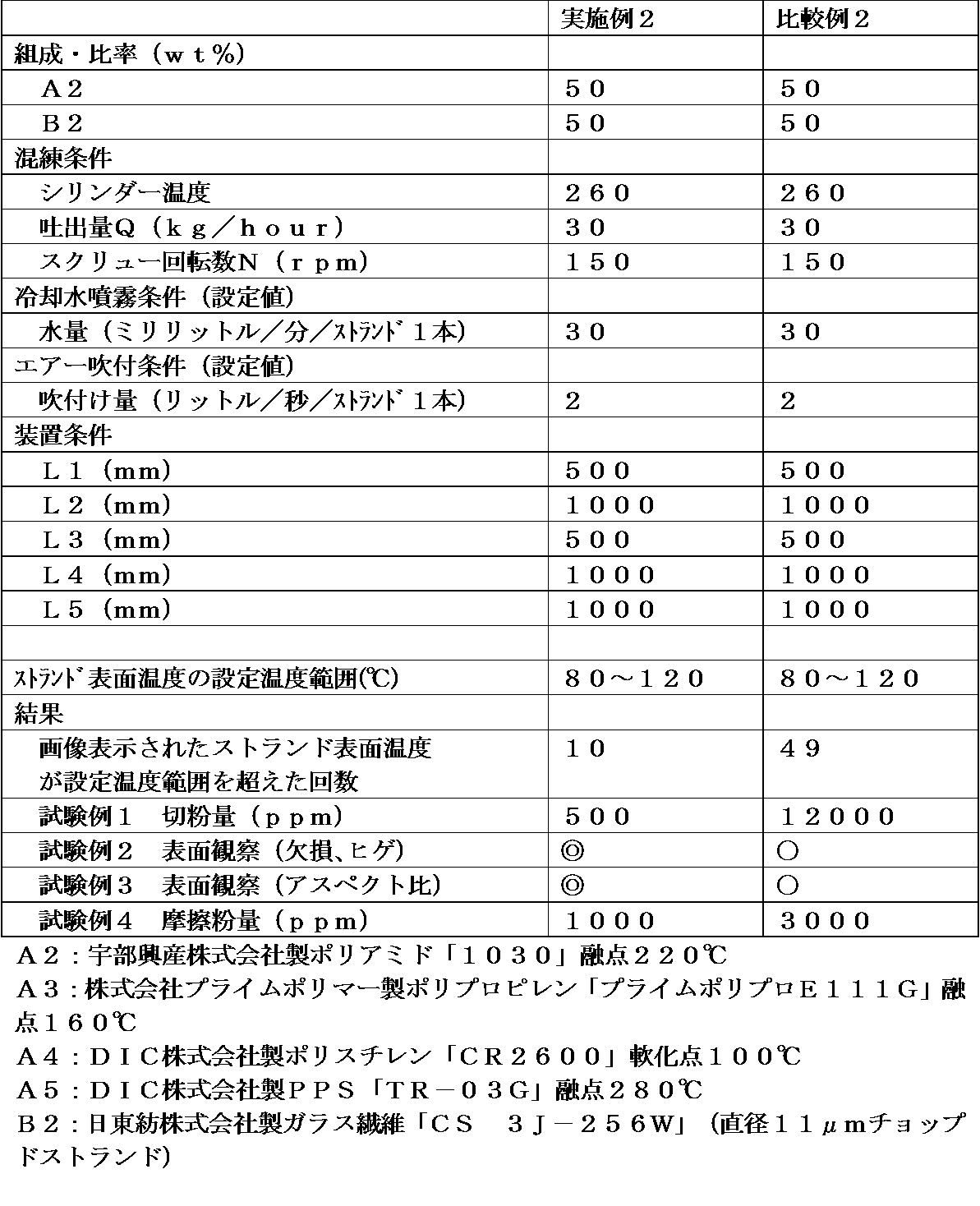

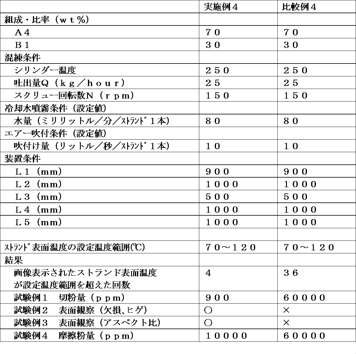

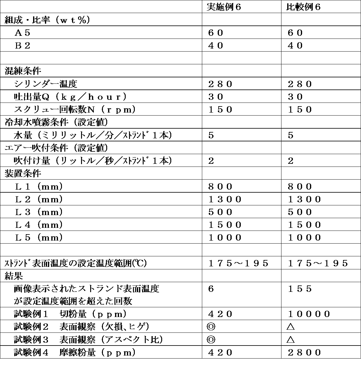
実施例1~6の製造方法は、切断前のストランド表面温度に応じて、水の噴霧量およびエアー吹付け量の調整が可能となり、ストランド温度の変化に対して、水の噴霧量およびエアー吹付け量の調整にタイムラグが生じることなく、または最小限に抑えることでき、実際にストランド表面温度が設定温度範囲を超える回数を抑えられただけでなく、当該設定温度範囲を超えた場合でもその超えた温度幅を大幅に抑制できることが確認できた。これに対して、比較例1~6の製造方法は、切断直後のペレットを採取して、その温度を測定せざるを得ず、ペレット温度の変化と参考値として記載したストランド表面温度の変化を対比しても明らかなとおり、ペレット温度の変化に対して、水の噴霧量およびエアー吹付け量の調整にタイムラグが生じざるを得ず、実際にストランド表面温度が変化するまでの間にさらに設定温度範囲を超える温度幅も大幅に大きくなるばかりか、設定温度範囲を超える回数も大幅に増加したことが確認できた。
その結果、実施例1~6は、それぞれ比較例1~6に比べて、長時間の連続製造を行っても、連粒ペレットの発生や、ペレット切断面のヒゲや欠損の抑制および切粉の発生が抑えられることを確認できた。また、輸送時のペレット同士の摩擦による粉発生状態を想定した加速度試験(試験例4)の結果からも実施例1~6の製造方法により、比較例1~6と比べ、摩擦粉の発生も大幅に抑制されたことを確認できた。
以上、添付図面を参照しながら本発明に係る好適な実施形態について説明したが、本発明は係る例に限定されないことは言うまでもない。上述した例において示した各構成部材の諸形状や組み合わせ等は一例であって、本発明の主旨から逸脱しない範囲において設計要求等に基づき種々変更可能である。
1 供給機
2 吐出口
3a、3b、3c 冷却水噴霧装置(水量調節バルブ付き)
4 測定装置
5 測定結果の表示装置
6a、6b、6c エアーブロワー(風量調節バルブ付き)
7 ストランド
8 ベルトコンベア
9 ストランドカッター
L1 供給機の吐出口2から吐出されたストランドが液体噴霧装置3a~3cより噴霧される液体と最初に接触するまでの距離
L2 供給機の吐出口2からストランドが液体噴霧装置3a~3cより噴霧される液体と最後に接触するまでの距離から、L1を差し引いた距離
L3 供給機の吐出口2からストランドが気体吹付け装置6a~6cより吹付けられる気体と最初に接触した距離から、L2を差し引いた距離
L4 供給機の吐出口2からストランドが気体吹付け装置6a~6cより吹付けられる気体と最後に接触した距離から、L3を差し引いた距離
L5 供給機の吐出口2からストランドカッターまでの距離から、L4を差し引いた距離
T タイムラグ
2 吐出口
3a、3b、3c 冷却水噴霧装置(水量調節バルブ付き)
4 測定装置
5 測定結果の表示装置
6a、6b、6c エアーブロワー(風量調節バルブ付き)
7 ストランド
8 ベルトコンベア
9 ストランドカッター
L1 供給機の吐出口2から吐出されたストランドが液体噴霧装置3a~3cより噴霧される液体と最初に接触するまでの距離
L2 供給機の吐出口2からストランドが液体噴霧装置3a~3cより噴霧される液体と最後に接触するまでの距離から、L1を差し引いた距離
L3 供給機の吐出口2からストランドが気体吹付け装置6a~6cより吹付けられる気体と最初に接触した距離から、L2を差し引いた距離
L4 供給機の吐出口2からストランドが気体吹付け装置6a~6cより吹付けられる気体と最後に接触した距離から、L3を差し引いた距離
L5 供給機の吐出口2からストランドカッターまでの距離から、L4を差し引いた距離
T タイムラグ
Claims (4)
- 熱可塑性樹脂および添加材を含む組成物を溶融した後、供給機から吐出させることにより得られたストランドをベルトコンベアで搬送する工程と、該ベルトコンベア上のストランドに向けて液体を噴霧する工程と、該ベルトコンベア上のストランドに向けて気体を吹付ける工程と、ストランドの表面温度を測定する工程と、ベルトコンベアにより搬送されるストランドをペレット状に切断する工程とを有するペレットの製造方法であって、
測定したストランドの表面温度に応じて、噴霧する液体量または液体温度を調整することを特徴とするペレットの製造方法。 - 測定したストランドの表面温度に応じて、吹付ける気体量または気体温度を調整することを特徴とする請求項1記載のペレットの製造方法。
- 熱可塑性樹脂および添加材を含む組成物を溶融した後、供給機から吐出させることにより得られたストランドを搬送するベルトコンベアと、該ベルトコンベアで搬送されるストランドに向けて液体を噴霧する液体噴霧装置と、該ベルトコンベアで搬送されるストランドに向けて気体を吹き付ける気体吹付け装置と、ストランドの表面温度の測定装置と、該ベルトコンベアで搬送されるストランドをペレット状に切断するストランドカッター装置を備え、ストランドの搬送方向に向かって、順に、前記液体噴霧装置と、前記気体吹付け装置と、前記ストランドカッター装置が配置されたペレット製造装置であって、
ストランドの表面温度の測定装置が、前記ストランドカッター装置よりも前に位置すること、前記液体噴霧装置が、噴霧する液体量または液体温度の調整機構を有すること、を特徴とするペレット製造装置。 - 前記気体吹付け装置が、吹付ける気体量または気体温度の調整機構を有する、請求項3記載のペレット製造装置。
Priority Applications (1)
| Application Number | Priority Date | Filing Date | Title |
|---|---|---|---|
| JP2017566886A JPWO2018003773A1 (ja) | 2016-06-30 | 2017-06-27 | ペレット製造装置およびそれを用いるペレットの製造方法 |
Applications Claiming Priority (2)
| Application Number | Priority Date | Filing Date | Title |
|---|---|---|---|
| JP2016-130167 | 2016-06-30 | ||
| JP2016130167 | 2016-06-30 |
Publications (1)
| Publication Number | Publication Date |
|---|---|
| WO2018003773A1 true WO2018003773A1 (ja) | 2018-01-04 |
Family
ID=60785371
Family Applications (1)
| Application Number | Title | Priority Date | Filing Date |
|---|---|---|---|
| PCT/JP2017/023501 Ceased WO2018003773A1 (ja) | 2016-06-30 | 2017-06-27 | ペレット製造装置およびそれを用いるペレットの製造方法 |
Country Status (2)
| Country | Link |
|---|---|
| JP (1) | JPWO2018003773A1 (ja) |
| WO (1) | WO2018003773A1 (ja) |
Cited By (2)
| Publication number | Priority date | Publication date | Assignee | Title |
|---|---|---|---|---|
| EP3482899A4 (en) * | 2016-07-06 | 2020-02-26 | DIC Corporation | PELLET PRODUCTION DEVICE AND PELLET PRODUCTION METHOD |
| CN112793035A (zh) * | 2021-01-27 | 2021-05-14 | 吉安茹姿科技有限公司 | 一种光降解聚丙烯塑料母粒制造装置及制造工艺 |
Citations (6)
| Publication number | Priority date | Publication date | Assignee | Title |
|---|---|---|---|---|
| JPS5574821A (en) * | 1978-12-01 | 1980-06-05 | Toray Ind Inc | Pelletizer for syhthetic resin |
| JPH04269511A (ja) * | 1991-02-25 | 1992-09-25 | O M Ltd | ストランドの冷却長調整装置 |
| JP2004202815A (ja) * | 2002-12-25 | 2004-07-22 | Tokki Kk | ストランド冷却装置及び冷却方法 |
| JP2004268421A (ja) * | 2003-03-10 | 2004-09-30 | Toray Ind Inc | ストランドカッターおよびそれを用いたペレットの製造方法 |
| JP2006159849A (ja) * | 2004-12-10 | 2006-06-22 | Tokki Kk | ストランド冷却装置、ストランド冷却方法及びペレット製造方法、並びに制御プログラム |
| JP2011173269A (ja) * | 2010-02-23 | 2011-09-08 | Toray Ind Inc | 熱可塑性樹脂ペレットの製造装置およびその製造方法 |
-
2017
- 2017-06-27 JP JP2017566886A patent/JPWO2018003773A1/ja active Pending
- 2017-06-27 WO PCT/JP2017/023501 patent/WO2018003773A1/ja not_active Ceased
Patent Citations (6)
| Publication number | Priority date | Publication date | Assignee | Title |
|---|---|---|---|---|
| JPS5574821A (en) * | 1978-12-01 | 1980-06-05 | Toray Ind Inc | Pelletizer for syhthetic resin |
| JPH04269511A (ja) * | 1991-02-25 | 1992-09-25 | O M Ltd | ストランドの冷却長調整装置 |
| JP2004202815A (ja) * | 2002-12-25 | 2004-07-22 | Tokki Kk | ストランド冷却装置及び冷却方法 |
| JP2004268421A (ja) * | 2003-03-10 | 2004-09-30 | Toray Ind Inc | ストランドカッターおよびそれを用いたペレットの製造方法 |
| JP2006159849A (ja) * | 2004-12-10 | 2006-06-22 | Tokki Kk | ストランド冷却装置、ストランド冷却方法及びペレット製造方法、並びに制御プログラム |
| JP2011173269A (ja) * | 2010-02-23 | 2011-09-08 | Toray Ind Inc | 熱可塑性樹脂ペレットの製造装置およびその製造方法 |
Cited By (3)
| Publication number | Priority date | Publication date | Assignee | Title |
|---|---|---|---|---|
| EP3482899A4 (en) * | 2016-07-06 | 2020-02-26 | DIC Corporation | PELLET PRODUCTION DEVICE AND PELLET PRODUCTION METHOD |
| US11534940B2 (en) | 2016-07-06 | 2022-12-27 | Dic Corporation | Apparatus for producing pellet and method for producing pellet |
| CN112793035A (zh) * | 2021-01-27 | 2021-05-14 | 吉安茹姿科技有限公司 | 一种光降解聚丙烯塑料母粒制造装置及制造工艺 |
Also Published As
| Publication number | Publication date |
|---|---|
| JPWO2018003773A1 (ja) | 2018-07-05 |
Similar Documents
| Publication | Publication Date | Title |
|---|---|---|
| WO2018008636A1 (ja) | ペレット製造装置およびペレット製造方法 | |
| JP7172405B2 (ja) | 熱可塑性樹脂組成物の製造方法 | |
| JP5206903B2 (ja) | 熱可塑性樹脂組成物およびそれを用いた成形品 | |
| JP5984073B2 (ja) | 液晶性ポリエステル樹脂ペレットの製造装置および製造方法 | |
| JP6773930B1 (ja) | 液晶ポリエステル樹脂成形体、液晶ポリエステル樹脂ペレット、及び液晶ポリエステル樹脂ペレットの製造方法 | |
| JPWO2018003773A1 (ja) | ペレット製造装置およびそれを用いるペレットの製造方法 | |
| CN108704378B (zh) | 一种石墨烯复合阻燃净风过滤材料及其制备方法 | |
| JP6398603B2 (ja) | 熱可塑性樹脂組成物の製造方法 | |
| JP6526988B2 (ja) | ポリアリーレンスルフィド樹脂組成物 | |
| JP6413424B2 (ja) | 熱可塑性樹脂組成物、その製造方法および成形体 | |
| JP4830327B2 (ja) | ポリフェニレンスルフィド樹脂組成物の製造方法 | |
| JP2018059040A (ja) | ポリアミド樹脂組成物およびそれを用いた成形品 | |
| JP7371371B2 (ja) | ポリフェニレンスルフィド樹脂組成物の製造方法 | |
| JP2015025025A (ja) | 放熱性電気・電子部品用熱可塑性樹脂組成物およびそれからなる放熱性電気・電子部品 | |
| JP7574656B2 (ja) | 樹脂組成物の製造方法 | |
| JP2016037598A (ja) | 繊維強化熱可塑性樹脂組成物およびその成形体 | |
| CN117659540A (zh) | 一种耐高温阻燃聚乙烯电缆料及其制备方法 | |
| JP2013169779A (ja) | ポリフェニレンサルファイド樹脂組成物ペレットの製造方法 | |
| JP2004059673A (ja) | 樹脂製パーティションおよびその製造方法 | |
| JP6495679B2 (ja) | ポリアリーレンスルフィド樹脂組成物 | |
| JP2006022326A (ja) | ポリフェニレンスルフィド樹脂組成物の製造方法 | |
| WO2023157411A1 (ja) | ポリアリーレンスルフィド樹脂組成物、成形品及びそれらの製造方法 | |
| JP2025119329A (ja) | 樹脂ペレットの風送装置、風送方法および製造方法 | |
| JP2024075813A (ja) | ペレット | |
| JP6880917B2 (ja) | 液晶性ポリエステル樹脂の製造方法 |
Legal Events
| Date | Code | Title | Description |
|---|---|---|---|
| ENP | Entry into the national phase |
Ref document number: 2017566886 Country of ref document: JP Kind code of ref document: A |
|
| 121 | Ep: the epo has been informed by wipo that ep was designated in this application |
Ref document number: 17820127 Country of ref document: EP Kind code of ref document: A1 |
|
| NENP | Non-entry into the national phase |
Ref country code: DE |
|
| 122 | Ep: pct application non-entry in european phase |
Ref document number: 17820127 Country of ref document: EP Kind code of ref document: A1 |