WO2018003041A1 - 投射型映像表示装置 - Google Patents
投射型映像表示装置 Download PDFInfo
- Publication number
- WO2018003041A1 WO2018003041A1 PCT/JP2016/069340 JP2016069340W WO2018003041A1 WO 2018003041 A1 WO2018003041 A1 WO 2018003041A1 JP 2016069340 W JP2016069340 W JP 2016069340W WO 2018003041 A1 WO2018003041 A1 WO 2018003041A1
- Authority
- WO
- WIPO (PCT)
- Prior art keywords
- light
- shielding plate
- light shielding
- projection
- mirror
- Prior art date
- Legal status (The legal status is an assumption and is not a legal conclusion. Google has not performed a legal analysis and makes no representation as to the accuracy of the status listed.)
- Ceased
Links
Images





Classifications
-
- G—PHYSICS
- G03—PHOTOGRAPHY; CINEMATOGRAPHY; ANALOGOUS TECHNIQUES USING WAVES OTHER THAN OPTICAL WAVES; ELECTROGRAPHY; HOLOGRAPHY
- G03B—APPARATUS OR ARRANGEMENTS FOR TAKING PHOTOGRAPHS OR FOR PROJECTING OR VIEWING THEM; APPARATUS OR ARRANGEMENTS EMPLOYING ANALOGOUS TECHNIQUES USING WAVES OTHER THAN OPTICAL WAVES; ACCESSORIES THEREFOR
- G03B21/00—Projectors or projection-type viewers; Accessories therefor
- G03B21/14—Details
- G03B21/20—Lamp housings
- G03B21/2066—Reflectors in illumination beam
-
- G—PHYSICS
- G03—PHOTOGRAPHY; CINEMATOGRAPHY; ANALOGOUS TECHNIQUES USING WAVES OTHER THAN OPTICAL WAVES; ELECTROGRAPHY; HOLOGRAPHY
- G03B—APPARATUS OR ARRANGEMENTS FOR TAKING PHOTOGRAPHS OR FOR PROJECTING OR VIEWING THEM; APPARATUS OR ARRANGEMENTS EMPLOYING ANALOGOUS TECHNIQUES USING WAVES OTHER THAN OPTICAL WAVES; ACCESSORIES THEREFOR
- G03B21/00—Projectors or projection-type viewers; Accessories therefor
-
- G—PHYSICS
- G03—PHOTOGRAPHY; CINEMATOGRAPHY; ANALOGOUS TECHNIQUES USING WAVES OTHER THAN OPTICAL WAVES; ELECTROGRAPHY; HOLOGRAPHY
- G03B—APPARATUS OR ARRANGEMENTS FOR TAKING PHOTOGRAPHS OR FOR PROJECTING OR VIEWING THEM; APPARATUS OR ARRANGEMENTS EMPLOYING ANALOGOUS TECHNIQUES USING WAVES OTHER THAN OPTICAL WAVES; ACCESSORIES THEREFOR
- G03B21/00—Projectors or projection-type viewers; Accessories therefor
- G03B21/14—Details
-
- G—PHYSICS
- G03—PHOTOGRAPHY; CINEMATOGRAPHY; ANALOGOUS TECHNIQUES USING WAVES OTHER THAN OPTICAL WAVES; ELECTROGRAPHY; HOLOGRAPHY
- G03B—APPARATUS OR ARRANGEMENTS FOR TAKING PHOTOGRAPHS OR FOR PROJECTING OR VIEWING THEM; APPARATUS OR ARRANGEMENTS EMPLOYING ANALOGOUS TECHNIQUES USING WAVES OTHER THAN OPTICAL WAVES; ACCESSORIES THEREFOR
- G03B21/00—Projectors or projection-type viewers; Accessories therefor
- G03B21/14—Details
- G03B21/145—Housing details, e.g. position adjustments thereof
-
- G—PHYSICS
- G03—PHOTOGRAPHY; CINEMATOGRAPHY; ANALOGOUS TECHNIQUES USING WAVES OTHER THAN OPTICAL WAVES; ELECTROGRAPHY; HOLOGRAPHY
- G03B—APPARATUS OR ARRANGEMENTS FOR TAKING PHOTOGRAPHS OR FOR PROJECTING OR VIEWING THEM; APPARATUS OR ARRANGEMENTS EMPLOYING ANALOGOUS TECHNIQUES USING WAVES OTHER THAN OPTICAL WAVES; ACCESSORIES THEREFOR
- G03B21/00—Projectors or projection-type viewers; Accessories therefor
- G03B21/14—Details
- G03B21/20—Lamp housings
Definitions
- the present invention relates to a projection-type image display device.
- a projection-type image display device such as a projector includes a light source, an illumination optical system that collects light emitted from the light source to generate illumination light, a display element that generates a projected image, and a screen image.
- Unnecessary light adversely affects the quality of the projected image, for example, by being reflected on the screen, and causes a reduction in contrast. For this reason, it is important to suppress unnecessary light from entering the projection lens in order to prevent deterioration of the quality of the projected image.
- Patent Document 1 is known as a conventional technique for suppressing unnecessary light from entering a projection lens.
- Patent Document 1 describes that “unnecessary light is shielded by a semicircular, circular, elliptical, or other shielding part provided at the aperture of a diaphragm of a projection optical system”.
- the image display range of the display element falls within the range of illumination light from the illumination optical system (hereinafter referred to as “projection light area”).
- the “minimum margin” mentioned here is caused by temperature changes in the environment in which the projection display device is used, temperature changes inside the projection display device, external impact such as vibration or dropping, etc. Thus, even when the position of the illumination light is deviated, this is the minimum margin necessary for preventing the image projected on the screen or the like from being defective or causing a color change.
- the change in the relative position between the effective display area and the projection light area before and after adjusting the angle of the light beam angle adjusting mirror will be described with reference to FIG.
- FIG. 12A if the angle of the light beam angle adjusting mirror is not appropriate, the projected light area is displaced with respect to the effective display area. Therefore, as shown in FIG. 12B, the angle is adjusted by rotating the light beam angle adjusting mirror around the X axis and / or the Y axis, and the region generated between the effective display region and the projection light region is vertically changed.
- it is necessary to adjust the relative positions of the effective display area and the projection light area so that the margin is substantially equal in the left-right direction and the necessary minimum margin is obtained.
- the projection-type image display device described in Patent Document 1 can prevent deterioration of the quality of the projected image by suppressing the incidence of unnecessary light to the projection lens by the light shielding plate. There is a problem that it is difficult to adjust the angle of the light beam angle adjusting mirror.
- the present invention has been made in view of the above-described actual situation, and an object of the present invention is to provide a projection-type image display device that can prevent deterioration of the quality of a projection image and can easily perform angle adjustment of a light beam angle adjustment mirror. Is to provide.
- a representative present invention includes a light source, an illumination optical system that collects light emitted from the light source to generate illumination light, a display element that generates a projected image,
- a projection optical system comprising: a projection optical system that projects illumination video generated by the display element upon incidence of illumination light generated by the illumination optical system, wherein the illumination optical system transmits illumination light A mirror that reflects toward the display element; a lens that is disposed between the mirror and the display element on an optical path of illumination light; a mirror angle adjustment mechanism that adjusts an angle of the mirror; and the mirror A light shielding plate that shields unnecessary light that is part of illumination light that is reflected by the lens and travels toward the display element via the lens, a first position that shields the unnecessary light, and the unnecessary light.
- the second position that allows irradiation of the display element Including a light shielding plate moving mechanism for moving between.
- FIG. 5 is a sectional view taken along line BB shown in FIG.
- FIG. 1 It is a schematic diagram for demonstrating the mechanism of angle adjustment of a light beam angle adjustment mirror, (a) shows the state which the light beam angle adjustment mirror is horizontal, (b) shows the state which inclined the light beam angle adjustment mirror.
- FIG. 1 It is a perspective view of the lens holding part which hold
- (a) is a figure which shows the state which the light-shielding plate has shielded a part of relay lens
- (b) is the light-shielding plate exposed the relay lens. It is a figure which shows a state. It is a figure which shows the insertion position of a jig
- FIG. 1 is a diagram showing an outline of a configuration example of a projection type video display apparatus according to an embodiment of the present invention.
- FIG. 2 is a perspective view showing the appearance of the optical engine of the projection display apparatus according to the present embodiment.
- a projection display apparatus 100 is, for example, a liquid crystal projector that receives an electric power supply from an external power source (not shown), projects an image on a screen (not shown), and displays the enlarged image.
- the projection display apparatus 100 includes, for example, a projection optical system 101, a display element 102, a display element driving unit 103, an illumination optical system 104, an illuminance sensor 105, a light source 106R, and a housing 190.
- the light source driver 107R drives the light source 106R according to control from the control unit 120.
- the light source driver 107G drives the light source 106G according to control from the control unit 120.
- the light source driver 107B drives the light source 106B according to the control from the control unit 120.
- the light source 106R emits red (R) light out of light for projecting an image based on control from the light source driver 107R. Based on the control from the light source driver 107G, the light source 106G emits green (G) light among light for projecting an image. Based on the control from the light source driver 107B, the light source 106B emits blue (B) light among light for projecting an image.
- the light source 106R, the light source 106G, and the light source 106B include, for example, an LED (Light Emitting Diode) light source, a laser light source, and the like, and are accommodated in the light source accommodating unit 130 as illustrated in FIG.
- LED Light Emitting Diode
- the light source cooling units 110R, 110G, and 110B are configured by, for example, heat pipes.
- the heat pipe is preferably made of a material having excellent heat conductivity. Examples of the material suitable for the heat pipe include metals such as copper.
- the illumination optical system 104 is an optical system having one or more optical elements such as one lens that converges light emitted from the light source 106R, the light source 106G, and the light source 106B to generate white light.
- Various optical components constituting the illumination optical system 104 are accommodated in the optical component accommodating portion 140 shown in FIG. The details of the internal configuration of the optical component housing unit 140 will be described later.
- the illuminance sensor 105 senses the amount of light for image projection in the illumination optical system 104 and transmits the sensed light amount data to the control unit 120.
- the display element 102 includes a transmissive or reflective liquid crystal panel, or a DMD (Digital Micromirror Device: registered trademark) panel.
- the display element 102 forms an image to be projected based on the video data transmitted from the control unit 120.
- the display element 102 projects an image formed on the element by transmitting or reflecting the light converged by the illumination optical system 104. Note that one or a plurality of display elements 102 may be provided.
- the projection optical system 101 is an optical system having one or more optical elements such as a lens or a mirror for enlarging an optical image of the display element 102 and projecting it on a screen or the like (not shown) as an image.
- the audio output unit 111 includes a speaker, an external output terminal, and the like, and outputs audio data related to the display video, and provides notification sound, warning sound, audio data, and the like related to operations and errors of the projection video display device 100. Or output.
- the video input unit 112 receives input of video data to be projected from an information processing terminal (not shown) such as a PC (Personal Computer), a tablet terminal, or a smartphone connected via a video input terminal (not shown), to the control unit 120. External interface to send.
- the video input terminal may have a plurality of types such as HDMI (High-Definition Multimedia Interface (registered trademark)), VGA (Video Graphics Array), and DVI (Digital Visual Interface). .
- the audio input unit 113 inputs audio data related to video data to be projected from an information processing terminal connected via an external interface.
- the input video data and audio data may be buffered in the memory 117 described later.
- the communication unit 114 has a function of communicating with an information processing terminal such as a PC, a tablet terminal, and a smartphone (not shown) and inputting / outputting various control signals.
- the operation signal input unit 115 is an input interface for performing an operation on the projection type video display device 100, and includes, for example, operation buttons provided on the main body of the projection type video display device 100 and a light receiving unit of a remote controller. , Input operation data from the user.
- the operation signal input unit 115 is an instruction from the user to the projection video display device 100 by operating a button or the like (not shown) via a panel or the like (not shown) provided on the casing 190 that is an exterior of the projection video display device 100. This is an external interface that accepts the input and transmits it to the control unit 120. Further, the operation signal input unit 115 may include a receiving unit, for example, and the receiving unit may be configured to accept an operation by a remote controller or the like (not shown).
- the non-volatile memory 116 is configured by a non-volatile memory such as a flash memory.
- the nonvolatile memory 116 stores a control program of the projection display apparatus 100, image data such as display icons for various operations, sound data such as notification sounds related to operations and errors, warning sounds, and the like. Moreover, you may make it hold
- the memory 117 includes a volatile memory such as a DRAM (Dynamic Random Access Memory).
- the memory 117 expands and holds a control program stored in the nonvolatile memory 116, various control data related to the projection display apparatus 100, and the like.
- the memory 117 also buffers projection target video data, audio data, and the like input via the video input unit 112 or the like.
- the light source heat radiation direction detection unit 118 detects the light source heat radiation direction of the light source cooling units 110R, 110G, and 110B.
- the light source heat radiation direction detection unit 118 transmits the detected light source heat radiation direction data to the control unit 120.
- the power supply 108 is supplied with power from an external power supply (not shown), and supplies power for operation to each unit constituting the projection display apparatus 100.
- the control unit 120 forms a projected image on the display element 102 and projects a video image by controlling the light source drivers 107R, 107G, and 107B, for example, by the operation of a microcomputer or the execution of a control program by a CPU (Central Processing Unit). It has a function of controlling the operation of each part of the projection display apparatus 100, such as control of light quantity based on light quantity data received from the illuminance sensor 105, control based on light source heat radiation direction data received from the light source heat radiation direction detection unit 118, and the like. .
- FIG. 3 is a perspective view showing an outline of a configuration example of the optical unit of the projection display apparatus according to the present embodiment.
- irradiated light emitted from three color light sources 106 R, 106 G, and 106 B arranged at different positions is illuminated by corresponding relay lenses 201, 202, and 203. These are combined into a luminous flux, and these are synthesized by color synthesis mirrors (dichroic mirrors) 204 and 205 to generate a white illumination luminous flux.
- dichroic mirrors color synthesis mirrors
- the irradiation light from the light source 106 ⁇ / b> G and the irradiation light from the light source 106 ⁇ / b> B are combined by the color combining mirror 205, and this and the irradiation light from the light source 106 ⁇ / b> R are combined by the color combining mirror 204.
- the synthesized white illumination light beam is incident on the rod integrator 207 via the relay lens 206 and the illuminance distribution is made uniform, and then taken out via the relay lens 208.
- the illumination light beam is reflected by the light beam angle adjusting mirror 170, then enters the TIR (Total Internal Reflection) prism 210 via the relay lens 209 and the mirror 175, and is totally reflected inside the TIR prism.
- the display element 102 (in this embodiment, a DMD panel) on which the image to be projected is generated is irradiated.
- the light reflected by the display element 102 passes through the TIR prism 210 and enters the projection optical system 101, and the projection optical system 101 projects an image on a screen or the like (not shown).
- the light beam angle adjusting mirror 170 corresponds to the “mirror” of the present invention
- the relay lens 209 corresponds to the “lens” of the present invention.
- a light shielding plate 250 for shielding unnecessary light is provided on the incident side (ray angle adjusting mirror 170 side) of the relay lens 209.
- the present embodiment is characterized in that a movable light shielding plate 250 is employed. Details of the structure of the light shielding plate 250 will be described later.
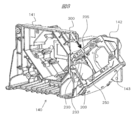
- FIG. 4 is a cross-sectional view of the optical component housing part 140 shown in FIG. 2 cut from above along the alternate long and short dash line and viewed from the A direction (front side).
- FIG. 5 is a cross-sectional view taken along the line BB shown in FIG.
- the optical component housing part 140 includes a first housing part 141 for mainly attaching the display element 102, the TIR prism 210, etc., a light beam angle adjusting mirror 170, and its angle adjusting mechanism. And a relay lens 209, a light shielding plate 250, and a second accommodating portion 142 for attaching the movable mechanism thereof.
- the second accommodating portion 142 corresponds to the “accommodating portion” of the present invention.
- the first accommodating portion 141 is a rectangular frame-shaped structure as shown in FIG. 4, and a TIR prism 210 or the like can be attached inside.
- a display element 102 (not shown) is arranged on the back side of the TIR prism 210.
- the second housing part 142 is a structure for holding the light beam angle adjusting mirror 170 in an inclined state and housing the relay lens 209, the light shielding plate 250, and the like inside. .
- the light beam angle adjusting mirror 170 held by the mirror holding member 144 is urged by a spring 145 on a mounting base 143 having a rectangular frame shape that is substantially the same size as the light beam angle adjusting mirror 170. It is held in the state. That is, the light beam angle adjustment mirror 170 is held at a predetermined distance from the mounting base 143 by the biasing force of the spring 145.
- a pair of springs 145 are provided on the diagonal line of the beam angle adjusting mirror 170, and adjusting screws 146a and 146b are inserted into the pair of springs 145, respectively.
- the center of the beam angle adjusting mirror 170 is supported by a fulcrum 147. Therefore, the angle (tilt) of the light beam angle adjusting mirror 170 can be freely adjusted around the fulcrum 147 by tightening or loosening the adjusting screws 146a and 146b.
- the mounting mirror 143, the mirror holding member 144, the spring 145, the adjusting screws 146a and 146b, and the fulcrum 147 constitute the “mirror angle adjusting mechanism” of the present invention.
- FIG. 6A and 6B are schematic diagrams for explaining the mechanism of angle adjustment of the light beam angle adjusting mirror 170.
- FIG. 6A shows a state in which the light beam angle adjusting mirror 170 is horizontal
- FIG. 6B shows the light beam angle adjusting mirror 170 tilted. Indicates the state.
- the light beam angle adjusting mirror 170 is parallel to the mounting base 143 by the biasing force of the spring 145. To be kept.
- the light beam angle adjusting mirror 170 is tilted about the fulcrum 147 and tilted by the biasing force of the spring 145. Kept in a state.
- the angle of the light beam angle adjusting mirror 170 is adjusted by turning the adjusting screws 146a and 146b.
- FIG. 7 shows the optical component housing part 140 in a state where the light beam angle adjusting mirror 170 is removed and the light shielding plate 250 is held at a position where the part of the relay lens 209 is shielded (first position). It is a perspective view which shows an internal structure.
- FIG. 8 shows the internal structure of the optical component housing part 140 in a state where the light beam angle adjusting mirror 170 is removed and the light shielding plate 250 is held at the position where the relay lens 209 is exposed (second position).
- FIG. 9A and 9B are perspective views of the lens holding member 230 that holds the relay lens 209.
- FIG. 9A is a diagram illustrating a state where the light shielding plate 250 shields a part of the relay lens 209
- FIG. 9B is a light shielding plate.
- 250 is a diagram illustrating a state in which the relay lens 209 is exposed.
- the lens holding member 230 to which the light shielding plate 250 and a movable mechanism of the light shielding plate 250 described later are attached is housed in the second housing portion 142 (lower part).
- the lens holding member 230 is provided with a large opening 233, and the relay lens 209 is fitted into the opening 233.
- a light shielding plate 250 is rotatably attached to the lens holding member 230 so as to cover a part of the relay lens 209.
- symbol 235 is an insertion port for inserting the jig
- the insertion port 235 is provided at a position facing a contact piece 253 of a light shielding plate 250 to be described later, in the mounting base 143 formed in the second housing portion 142.
- the light shielding plate 250 is made of a metal material having heat resistance such as stainless steel or aluminum, and is formed in a shape suitable for shielding unnecessary light.
- the light shielding plate 250 is formed in a substantially quarter elliptical shape, but the shape is not limited.
- Two insertion holes 254 are provided in the side edge portion of the light shielding plate 250 in the longitudinal direction so as to be spaced apart from each other along the longitudinal direction (vertical direction in FIG. 9).
- a round bar-shaped shaft member 251 is inserted through the two insertion holes 254.
- a contact piece 253 made of a member that is bent so as to cover approximately half of the shaft member 251 along the circumferential direction of the shaft member 251 and a notch 255 are provided. ing. The notch 255 is provided to avoid interference with the torsion spring 252 attached to the shaft member 251.
- the abutting piece 253 is a part that receives pressure from the jig 300 when the light shielding plate 250 is rotated.
- the lens holding member 230 is provided with a bearing portion 232 that rotatably supports one end of the shaft member 251 and a bearing portion 231 that rotatably supports the other end of the shaft member 251. Therefore, in a state where the shaft member 251 is inserted into the two insertion holes 254 of the light shielding plate 250 and both ends of the shaft member 251 are supported by the bearing portion 231 and the bearing portion 232, the light shielding plate 250 is Rotate around 251.
- a torsion spring 252 which is an example of an urging member, is mounted in the vicinity of the bearing portion 232 in the shaft member 251, and the light shielding plate 250 always causes a part of the relay lens 209 to be moved by the torsion spring 252.
- the light is biased to a light shielding position (first position) that shields unnecessary light.
- first position a light shielding position
- second position an allowable exposure position
- the shaft member 251, the insertion hole 254, the bearing portions 231 and 232, the torsion spring 252, and the contact piece 253 constitute the “light shielding plate movable mechanism” of the present invention.
- a round bar-shaped jig 300 is used in order to rotate the light shielding plate 250.
- the jig 300 is inserted from the insertion port 235, and the tip of the jig 300 is pressed against the contact piece 253.
- the contact piece 253 rotates around the shaft member 251 against the urging force of the torsion spring 252. To do.
- the light blocking plate 250 rotates around the shaft member 251 integrally with the contact piece 253.
- the light shielding plate 250 is automatically set to the exposed position by the insertion of the jig 300. It is characterized in that it is configured to be held by the device (hereinafter referred to as self-locking).
- self-locking the self-locking mechanism
- FIG. 10A and 10B are views showing the insertion position of the jig 300 and the rotation position of the light shielding plate 250.
- FIG. 10A shows a state where the jig 300 presses the contact piece 253 a little
- FIG. 10A shows a state where the jig 300 presses the contact piece 253 a little
- FIG. 10A shows a biasing force by the torsion spring 252 in the direction of the arrow in FIG. . Therefore, when the operator releases the hand holding the jig 300 in the state of FIG. 10A, the jig 300 is pushed back in the direction of the arrow Q in the figure by the urging force of the torsion spring 252.
- the tip of the jig 300 presses the contact piece 253 to rotate around the shaft member 251 in the R direction in the figure, and then the jig 300 is inserted. Since it is inserted to a predetermined position in the P direction in the drawing beyond the position of the previous contact piece 253, the light shielding plate 250 is held at the exposed position by overcoming the urging force of the torsion spring 252. Therefore, even if the operator removes the hand holding the jig 300, the light shielding plate 250 is held at the exposed position, so that the illumination light incident on the relay lens 209 is not shielded. That is, irradiation of unnecessary light to the display element 102 is allowed.
- ⁇ Angle Adjustment Procedure of Light Beam Angle Adjustment Mirror 170 For example, when it becomes necessary to adjust the angle of the light beam angle adjusting mirror 170 in the repair or inspection before shipment of the projection display apparatus 100, first, the operator removes the cover 150 of the optical component housing unit 140. Then, as shown in FIGS. 4 and 5, since the insertion port 235 is exposed, the operator inserts the jig 300 from the insertion port 235 and presses it against the contact piece 253.
- the contact piece 253 rotates around the shaft member 251 together with the light shielding plate 250.
- the tip of the jig 300 further passes the position of the contact piece 253 before insertion of the jig 300 and further pushes the jig 300 to a predetermined position in the P direction of FIG. 10B, as shown in FIG. 10B.
- the rotation operation of the contact piece 253 is locked by the jig 300.
- the light shielding plate 250 rotates from a light shielding position (see FIG. 7) that shields a part of the relay lens 209 to an exposure position (see FIG. 8) that exposes the relay lens 209, and is held at the exposed position (self-locking). ).
- the adjustment screws 146a and 146b are tightened or loosened to adjust the angle of the light beam angle adjusting mirror 170 easily and with high accuracy. Can do.
- the angle adjustment work of the light beam angle adjusting mirror 170 is easy. is there.
- the light shielding plate 250 is held at a light shielding position where a part of the relay lens 209 is shielded by the urging force of the torsion spring 252 when the jig 300 is pulled out. Therefore, in a normal use state, unnecessary light is shielded by the light shielding plate 250, so that the quality of the projected image does not deteriorate.
- the torsion spring 252 can be replaced with a magnet or the like as long as the light shielding plate 250 and the contact piece 253 can be urged. Moreover, it can also be set as the structure which combined the torsion spring 252 and the magnet.
- the purpose of moving the light shielding plate 250 is to prevent the outer peripheral portion of the projected light area to be narrowed by blocking unnecessary light when the angle of the light beam angle adjusting mirror 170 is adjusted (FIG. 5). 13). In other words, if the outer periphery of the projection light area is not narrowed, there is no problem in adjusting the light beam angle adjustment mirror 170 to the optimum angle even if a shadow is formed inside the projection light area. .
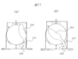
- FIG. 11 is a view showing a modification of the movable mechanism of the light shielding plate 250.
- FIG. 11A is a position (first position) where the light shielding plate 250 shields a part of the relay lens 209 and shields unnecessary light.
- State (b) shows a state in which the light shielding plate 250 is in a position (second position) where the central portion of the relay lens 209 is shielded.
- the light shielding plate 250 is connected to the arm 257 and rotates around a pin 258 serving as a shaft member.
- the light shielding plate 250 shields unnecessary light by shielding a part of the relay lens 209 by a spring as an urging member (not shown). ).
- the light shielding plate 250 acts against the biasing force of the spring by a jig (not shown)
- the light shielding plate 250 is moved from the light shielding position to the central portion ( By retracting to a different part), the center part can be shielded and rotated to a retracted position (second position) that allows the display element 102 to be irradiated with unnecessary light.
- the light shielding plate 250 may be configured to slide the light shielding plate 250 along the in-plane direction of the relay lens 209 in addition to the configuration of rotating around the shaft member 251 or the pin 258, for example.
- the light shielding plate 250 is provided on the incident side of the relay lens 209.
- the light shielding plate 250 may be provided at a position on the output side of the relay lens 209. Even in this case, in the normal usage mode of the projection type image display device, when unnecessary light is shielded to ensure a high quality image and the angle adjustment of the light beam angle adjustment mirror 170 is necessary, The angle can be adjusted easily and with high accuracy.
Landscapes
- Physics & Mathematics (AREA)
- General Physics & Mathematics (AREA)
- Projection Apparatus (AREA)
- Transforming Electric Information Into Light Information (AREA)
- Non-Portable Lighting Devices Or Systems Thereof (AREA)
Abstract
投射画像の品質の低下を防ぎ、かつ、光線角度調整ミラーの角度調整を容易に行うこと。光源(106)と、照明光学系(104)と、表示素子(102)と、投射光学系(101)と、を備えた投射型映像表示装置であって、照明光学系は、照明光を前記表示素子に向けて反射させるミラー(170)と、照明光の光路上であってミラーと表示素子との間に配置されるレンズ(209)と、ミラーの角度を調整するミラー角度調整機構と、ミラーで反射し、レンズを介して表示素子に向かう照明光の一部である不要光を遮光する遮光板(250)と、遮光板を、不要光を遮光する第1の位置と、不要光の表示素子への照射を許容する第2の位置との間で可動させる遮光板可動機構(231、232、251、252、253、254)と、を含む。
Description
本発明は、投射型映像表示装置に関する。
一般に、プロジェクタなどの投射型映像表示装置は、光源と、光源から発せられた光を集光して照明光を生成する照明光学系と、投射する映像を生成する表示素子と、映像をスクリーン等に投射する投射光学系と、を備える。照明光学系で生成した照明光は、ミラーにより反射されて、表示素子に照射される。
表示素子を照射する照明光の一部は、映像の投射に不要な光(以下、「不要光」という)として投射光学系の投射レンズに入射する。不要光は、スクリーン上に映るなどして投射画像の品質に悪影響を及ぼし、コントラストを低下させる要因となる。そのため、不要光の投射レンズへの入射を抑制することは、投射画像の品質の低下を防ぐために重要である。
不要光の投射レンズへの入射を抑制する従来技術として、例えば特許文献1が公知である。特許文献1には、「投射光学系の絞りの開口に設けられた半円形、円形、楕円形等の遮蔽部によって、不要光を遮光すること」が記載されている。
この種の投射型映像表示装置では、表示素子の映像表示範囲(以下、「有効表示領域」という)が、照明光学系からの照明光(以下、「投射光領域」という)の範囲に収まり、かつ、有効表示領域と投射光領域との間に生じる領域が上下及び左右方向に略均等かつ必要最小限のマージンとなるように、照明光学系からの照明光を表示素子へ反射する特定のミラー(以下、「光線角度調整ミラー」という)の角度調整を行う必要がある。
ここで言う「必要最小限のマージン」とは、投射型映像表示装置を使用している環境の温度変化や投射型映像表示装置内部の温度変化、振動や落下等の外部からの衝撃等が原因となって照明光の位置がずれた場合でも、スクリーン等に投射される映像に欠けや色の変化等の不具合を起こさないために必要な最小限のマージンのことである。
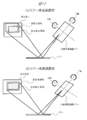
光線角度調整ミラーの角度調整前後における有効表示領域と投射光領域との相対位置の変化について、図12を用いて説明する。図12(a)に示すように、光線角度調整ミラーの角度が適正でないと、有効表示領域に対して投射光領域がずれた位置関係となってしまう。そのため、図12(b)に示すように、光線角度調整ミラーをX軸及び/又はY軸回りに回転させて角度を調整して、有効表示領域と投射光領域との間に生じる領域が上下及び左右方向に略均等で必要最小限のマージンとなるように、有効表示領域と投射光領域との相対的な位置調整をする必要がある。
特許文献1に記載の投射型映像表示装置に対して上記した光線角度調整ミラーの角度調整を行う場合、遮光板によって不要光が遮光されるため、光線角度調整ミラーの角度調整が困難であるという課題がある。この課題について図13を用いて説明する。図13(a)に示すように、遮光板がない状態では、本来の投射光領域ABCD全体がスクリーン上に投射されるため、有効表示領域abcdに対して投射光領域ABCDが最適な位置で重なり合うように光線角度調整ミラーの角度調整を行うことは簡単である。
しかしながら、遮光板がある状態では、図13(b)に示すように、遮光板によって不要光が遮光されるため、スクリーン上に投射される実際の投射光領域は有効表示領域abcdと同じ範囲(abcd)になる。即ち、有効表示領域abcdと本来の投射光領域ABCDとの間に生じる領域(図13(b)の斜線領域)がスクリーン上に投射されない。そのため、図13(b)に示す遮光板がある状態では、有効表示領域abcdが投射光領域ABCDの範囲に収まり、かつ、有効表示領域abcdと投射光領域ABCDとの間に生じる領域が上下及び左右方向に略均等で必要最小限のマージンとなるように光線角度調整ミラーの角度調整を行うことは容易ではない。
このように、特許文献1に記載の投射型映像表示装置は、遮光板により不要光の投射レンズへの入射を抑制することで、投射画像の品質の低下を防ぐことができるが、その一方で、光線角度調整ミラーの角度調整が困難であるという課題がある。
本発明は、上記した実状に鑑みてなされたものであり、その目的は、投射画像の品質の低下を防ぎ、かつ、光線角度調整ミラーの角度調整を容易に行うことのできる投射型映像表示装置を提供することにある。
上記目的を達成するために、代表的な本発明は、光源と、光源から発せられた光を集光して照明光を生成する照明光学系と、投射する映像を生成する表示素子と、前記照明光学系で生成した照明光を入射して、前記表示素子で生成された映像を投射する投射光学系と、を備えた投射型映像表示装置であって、前記照明光学系は、照明光を前記表示素子に向けて反射させるミラーと、照明光の光路上であって前記ミラーと前記表示素子との間に配置されるレンズと、前記ミラーの角度を調整するミラー角度調整機構と、前記ミラーで反射し、前記レンズを介して前記表示素子に向かう照明光の一部である不要光を遮光する遮光板と、前記遮光板を、前記不要光を遮光する第1の位置と、前記不要光の前記表示素子への照射を許容する第2の位置との間で可動させる遮光板可動機構と、を含む。
本発明によれば、投射画像の品質の低下を防ぎ、かつ、光線角度調整ミラーの角度調整を容易に行うことのできる投射型映像表示装置を提供することができる。なお、上記した以外の課題、構成及び効果は、以下の実施の形態の説明により明らかにされる。
以下、本発明の実施の形態を図面に基づいて詳細に説明する。なお、実施の形態を説明するための全図において、同一部には原則として同一の符号を付し、その繰り返しの説明は省略する。一方で、ある図において符号を付して説明した部位について、他の図の説明の際に再度の図示はしないが同一の符号を付して言及する場合がある。
<装置構成(全体)>
図1は、本発明の一実施の形態である投射型映像表示装置の構成例についての概要を示す図である。図2は、本実施の形態に係る投射型映像表示装置の光学エンジンの外観を示す斜視図である。
図1は、本発明の一実施の形態である投射型映像表示装置の構成例についての概要を示す図である。図2は、本実施の形態に係る投射型映像表示装置の光学エンジンの外観を示す斜視図である。
図1において、投射型映像表示装置100は、例えば、図示しない外部電源から電力の供給を受けて、図示しないスクリーンに対して映像を投射して拡大表示する液晶プロジェクタ等である。
投射型映像表示装置100は、図1に示すように、例えば、筐体190内に、投射光学系101、表示素子102、表示素子駆動部103、照明光学系104、照度センサ105、光源106R、光源106G、光源106B、光源ドライバ107R、光源ドライバ107G、光源ドライバ107B、電源108、光源冷却部110R、光源冷却部110G、光源冷却部110B、音声出力部111、映像入力部112、音声入力部113、通信部114、操作信号入力部115、不揮発性メモリ116、メモリ117、制御部120、などの各部を有する。
光源ドライバ107Rは、制御部120からの制御に従って光源106Rを駆動する。光源ドライバ107Gは、制御部120からの制御に従って光源106Gを駆動する。光源ドライバ107Bは、制御部120からの制御に従って光源106Bを駆動する。
光源106Rは、光源ドライバ107Rからの制御に基づいて、画像を投射する光のうち赤色(R)の光を発光する。光源106Gは、光源ドライバ107Gからの制御に基づいて、画像を投射する光のうち緑色(G)の光を発光する。光源106Bは、光源ドライバ107Bからの制御に基づいて、画像を投射する光のうち青色(B)の光を発光する。
光源106R、光源106G、光源106Bは、例えば、LED(Light Emitting Diode)光源、レーザー光源等により構成され、図2に示すように光源収容部130に収容される。
光源冷却部110R、110G、110Bは、例えばヒートパイプ等で構成される。ヒートパイプは、熱伝導性に優れた材質により形成されていることが望ましい。ヒートパイプに適した材質としては、例えば銅等の金属等が挙げられる。
照明光学系104は、光源106R、光源106G、光源106Bから発光された光を収束させて白色光を生成する1つ以上のレンズなどの光学要素を有する光学系である。照明光学系104を構成する各種光学部品は、図2に示す光学部品収容部140に収容される。なお、光学部品収容部140の内部構成の詳細については、後述する。
照度センサ105は、照明光学系104において画像投射用の光の光量をセンシングし、センシングした光量データを制御部120に送信する。
表示素子102は、透過型または反射型液晶パネル、あるいはDMD(Digital Micromirror Device:登録商標)パネル等により構成される。表示素子102は、制御部120から送信された映像データに基づいて投射する画像を形成する。表示素子102は、照明光学系104により収束された光を透過もしくは反射させて素子に形成された画像を投射する。なお、表示素子102は、1枚あるいは複数枚でも良い。
投射光学系101は、表示素子102の光学像を拡大して、画像として図示しないスクリーン等に対して投射する1つ以上のレンズまたはミラーなどの光学要素を有する光学系である。
音声出力部111は、スピーカーや外部出力端子等を備え、表示映像に関連する音声データを出力したり、投射型映像表示装置100の操作やエラー等に係る通知音や警告音、音声データなどを出力したりする。
映像入力部112は、図示しない映像入力端子を介して接続された図示しないPC(Personal Computer)やタブレット端末、スマートフォン等の情報処理端末から、投射する映像データの入力を受け付けて、制御部120へ送信する外部インタフェースである。なお、映像入力端子は、例えば、HDMI(High-Definition Multimedia Interface高精細度マルチメディアインタフェース(登録商標))やVGA(Video Graphics Array)、DVI(Digital Visual Interface)など複数種類有していてもよい。
音声入力部113は、外部インタフェースを介して接続された情報処理端末から、投射する映像データに関連する音声データ等を入力する。入力した映像データや音声データは後述するメモリ117にバッファリングされてもよい。
通信部114は、例えば図示しないPC、タブレット端末、スマートフォン等の情報処理端末と通信を行い、各種制御信号等を入出力する機能を有する。操作信号入力部115は、投射型映像表示装置100に対する操作を行うための入力インタフェースであり、例えば、投射型映像表示装置100の本体上に設けられた操作ボタンや、リモコンの受光部により構成され、ユーザからの操作データを入力する。
操作信号入力部115は、投射型映像表示装置100の外装である筐体190に設けられた図示しないパネル等を介して、図示しないボタン等の操作によりユーザからの投射型映像表示装置100に対する指示の入力を受け付けて、制御部120に送信する外部インタフェースである。また、操作信号入力部115は、例えば受信部を備え、受信部が図示しないリモコン等による操作を受け付けるように構成されていてもよい。
不揮発性メモリ116は、フラッシュメモリ等の不揮発性メモリにより構成されている。不揮発性メモリ116は、投射型映像表示装置100の制御プログラム、各種操作用の表示アイコンなどの画像データ、操作やエラー等に係る通知音、警告音等の音声データ等を記憶する。また、投射型映像表示装置100単独で映像を投射するための映像データ(テンプレート画像などを含む)を保持するようにしてもよい。
メモリ117は、DRAM(Dynamic Random Access Memory)等の揮発性メモリにより構成されている。メモリ117は、不揮発性メモリ116に記憶された制御プログラム、投射型映像表示装置100に係る各種制御用データ等を展開して保持したりする。また、メモリ117は、映像入力部112等を介して入力された投射対象の映像データ、音声データ等をバッファリングしたりする。
光源放熱方向検出部118は、光源冷却部110R、110G、110Bの光源放熱方向を検出する。光源放熱方向検出部118は、検出した光源放熱方向データを制御部120に送信する。
電源108は、図示しない外部電源からの電力の供給を受けて、投射型映像表示装置100を構成する各部に対して、動作用の電力を供給する。
制御部120は、例えば、マイコンの動作や、CPU(Central Processing Unit)による制御プログラムの実行などにより、表示素子102における投射画像の形成と、光源ドライバ107R、107G、107Bの制御による映像の投射、照度センサ105から受信した光量データに基づいた光量の制御、光源放熱方向検出部118から受信した光源放熱方向データに基づいた制御等、投射型映像表示装置100の各部の動作を制御する機能を有する。
<装置構成(光学系)>
図3は、本実施の形態に係る投射型映像表示装置の光学ユニットの構成例について概要を示した斜視図である。図3に示すように、異なる位置にそれぞれ配置された光源106R、光源106G、および光源106Bの3色の光源から発光されて拡散する照射光が、対応するリレーレンズ201、202、および203により照明光束とされ、これらが色合成ミラー(ダイクロイックミラー)204、および205により合成されて白色の照明光束が生成される。図3の例では、光源106Gからの照射光と光源106Bからの照射光とが色合成ミラー205により合成され、さらにこれと光源106Rからの照射光とが色合成ミラー204により合成される。
図3は、本実施の形態に係る投射型映像表示装置の光学ユニットの構成例について概要を示した斜視図である。図3に示すように、異なる位置にそれぞれ配置された光源106R、光源106G、および光源106Bの3色の光源から発光されて拡散する照射光が、対応するリレーレンズ201、202、および203により照明光束とされ、これらが色合成ミラー(ダイクロイックミラー)204、および205により合成されて白色の照明光束が生成される。図3の例では、光源106Gからの照射光と光源106Bからの照射光とが色合成ミラー205により合成され、さらにこれと光源106Rからの照射光とが色合成ミラー204により合成される。
合成された白色の照明光束は、リレーレンズ206を介してロッドインテグレータ207に入射して照度分布が均一化された後にリレーレンズ208を介して取り出される。この照明光束は、光線角度調整ミラー170により反射された後、リレーレンズ209、ミラー175を介してTIR(Total Internal Reflection:内部全反射)プリズム210に入射し、TIRプリズムの内部で全反射されて、投射する映像が生成された表示素子102(本実施の形態ではDMDパネル)に照射される。そして、表示素子102により反射された光は、TIRプリズム210を透過して投射光学系101に入射し、投射光学系101によって図示しないスクリーン等に映像が投射される。
本実施の形態において、光線角度調整ミラー170は本発明の「ミラー」に、リレーレンズ209は本発明の「レンズ」にそれぞれ相当する。
リレーレンズ209の入射側(光線角度調整ミラー170側)には、不要光を遮光するための遮光板250が設けられている。本実施の形態では、可動式の遮光板250を採用している点に特徴がある。なお、遮光板250の構造の詳細については、後述する。
<ミラー角度調整機構>
図4は、図2に示す光学部品収容部140を一点鎖線に沿って上方から切断して、A方向(正面側)から見た断面図である。図5は、図4に示すB-B断面図である。図4及び図5に示すように、光学部品収容部140は、主に表示素子102やTIRプリズム210などを取り付けるための第1収容部141と、主に光線角度調整ミラー170とその角度調整機構や、リレーレンズ209、遮光板250とその可動機構などを取り付けるための第2収容部142と、を含む。なお、本実施の形態において、第2収容部142は本発明の「収容部」に相当する。
図4は、図2に示す光学部品収容部140を一点鎖線に沿って上方から切断して、A方向(正面側)から見た断面図である。図5は、図4に示すB-B断面図である。図4及び図5に示すように、光学部品収容部140は、主に表示素子102やTIRプリズム210などを取り付けるための第1収容部141と、主に光線角度調整ミラー170とその角度調整機構や、リレーレンズ209、遮光板250とその可動機構などを取り付けるための第2収容部142と、を含む。なお、本実施の形態において、第2収容部142は本発明の「収容部」に相当する。
第1収容部141は、図4に示すように矩形枠状の構造体であり、内部にTIRプリズム210等を取り付けることができる。TIRプリズム210の背面側には、図示しない表示素子102が配置されている。
一方、第2収容部142は、図5に示すように光線角度調整ミラー170を斜めに傾けた状態で保持すると共に、内部にリレーレンズ209や遮光板250等を収容するための構造体である。具体的には、光線角度調整ミラー170と略等しい大きさの矩形枠状から成る取付台143の上に、ミラー保持部材144に保持された状態の光線角度調整ミラー170がバネ145により付勢された状態で保持されている。即ち、光線角度調整ミラー170は、バネ145の付勢力によって取付台143と所定の間隔を空けて保持されている。
バネ145は光線角度調整ミラー170の対角線上に一対で設けられており、一対のバネ145にはそれぞれ調整ネジ146a、146bが挿入されている。また、光線角度調整ミラー170の中心は支点147により支持されている。そのため、調整ネジ146a、146bを締め付けたり緩めたりすることにより、支点147を中心として光線角度調整ミラー170の角度(傾き)を自在に調整することができる。
本実施の形態において、取付台143、ミラー保持部材144、バネ145、調整ネジ146a、146b、及び支点147により、本発明の「ミラー角度調整機構」が構成されている。
次に、光線角度調整ミラー170の角度調整について、図を用いて説明する。図6は、光線角度調整ミラー170の角度調整のメカニズムを説明するための模式図であり、(a)は光線角度調整ミラー170が水平な状態、(b)は光線角度調整ミラー170を傾けた状態を示す。図6(a)に示すように、2つの調整ネジ146a、146bの頭部の高さ位置が互いに等しい場合、光線角度調整ミラー170はバネ145の付勢力により取付台143に対して平行な状態に保たれる。
一方、図6(b)に示すように、一方の調整ネジ146bを締め付け、他方の調整ネジ146aを緩めると、光線角度調整ミラー170は支点147を中心に傾き、バネ145の付勢力によって傾いた状態に保持される。このように、本実施の形態では、調整ネジ146a、146bを回すことによって、光線角度調整ミラー170の角度調整が行われる。
<遮光板可動機構>
図7は、光線角度調整ミラー170を取り外した状態、かつ、遮光板250がリレーレンズ209の一部を遮蔽した位置(第1の位置)に保持されている状態における、光学部品収容部140の内部構造を示す斜視図である。図8は、光線角度調整ミラー170を取り外した状態、かつ、遮光板250がリレーレンズ209を露出させた位置(第2の位置)に保持されている状態における、光学部品収容部140の内部構造を示す斜視図である。図9はリレーレンズ209を保持するレンズ保持部材230の斜視図であって、(a)は遮光板250がリレーレンズ209の一部を遮蔽している状態を示す図、(b)は遮光板250がリレーレンズ209の露出させた状態を示す図である。
図7は、光線角度調整ミラー170を取り外した状態、かつ、遮光板250がリレーレンズ209の一部を遮蔽した位置(第1の位置)に保持されている状態における、光学部品収容部140の内部構造を示す斜視図である。図8は、光線角度調整ミラー170を取り外した状態、かつ、遮光板250がリレーレンズ209を露出させた位置(第2の位置)に保持されている状態における、光学部品収容部140の内部構造を示す斜視図である。図9はリレーレンズ209を保持するレンズ保持部材230の斜視図であって、(a)は遮光板250がリレーレンズ209の一部を遮蔽している状態を示す図、(b)は遮光板250がリレーレンズ209の露出させた状態を示す図である。
図7~図9に示すように、遮光板250と後述する遮光板250の可動機構を取り付けたレンズ保持部材230は、第2収容部142の内部(下部)に収容されている。レンズ保持部材230には大きな開口233が設けられており、この開口233にリレーレンズ209が嵌め込まれる。そして、リレーレンズ209の一部を覆うように遮光板250がレンズ保持部材230に回動可能に取り付けられている。
なお、符号235は、後述する治具300を挿入するための挿入口である。挿入口235は、第2収容部142に形成された取付台143のうち、後述する遮光板250の当接片253を臨む位置に設けられている。
遮光板250は、例えばステンレスやアルミなどの耐熱性を有する金属材料から成り、不要光を遮光するのに好適な形状に形成される。例えば、本実施の形態において、遮光板250は略1/4楕円形状に形成されているが、その形状は問わない。遮光板250の長手方向の側縁部には、その長手方向(図9の上下方向)に沿って2つの挿通孔254が互いに間隔を空けて設けられている。2つの挿通孔254には、丸棒状の軸部材251が挿通される。
遮光板250の一端側には、軸部材251の周方向に沿って、軸部材251の略半分程度を覆うように屈曲する部材で構成される当接片253と、切欠き255とが設けられている。切欠き255は、軸部材251に装着されるトーションバネ252との干渉を避けるために設けられる。当接片253は、遮光板250を回動させる際に治具300による押圧を受ける部位である。
一方、レンズ保持部材230には、軸部材251の一端を回動自在に支持する軸受部232と、軸部材251の他端を回動自在に支持する軸受部231と、が設けられている。よって、遮光板250の2つの挿通孔254に軸部材251が挿通され、かつ、軸部材251の両端が軸受部231と軸受部232とによってそれぞれ支持された状態において、遮光板250は、軸部材251の回りを回動する。
ここで、軸部材251のうち軸受部232の近傍には付勢部材の一例であるトーションバネ252が装着されており、トーションバネ252により、遮光板250は、常時、リレーレンズ209の一部を遮蔽して不要光を遮光する遮光位置(第1の位置)に付勢されている。そして、トーションバネ252の付勢力に抗する力が遮光板250に作用した場合に、遮光板250は、遮光位置から、リレーレンズ209を露出して不要光が表示素子102へ照射されるのを許容する露出位置(第2の位置)まで回動可能である。
本実施の形態において、軸部材251、挿通孔254、軸受部231、232、トーションバネ252、及び当接片253により、本発明の「遮光板可動機構」が構成されている。
遮光板250を回動させるためには、丸棒状の治具300を使用する。図7に示すように、治具300を挿入口235から挿入して、治具300の先端を当接片253に押し当てる。図8に示すように、治具300を挿入方向(図8の矢印方向)に沿ってさらに押し込むと、当接片253がトーションバネ252の付勢力に抗して軸部材251の回りに回動する。その結果、遮光板250が当接片253と一体で軸部材251の回りを回動する。
ここで、本実施の形態では、治具300の先端が当接片253の先端を越えた所定の挿入位置まで挿入されると、この治具300の挿入によって遮光板250が露出位置に自動的に保持される構成(以下、セルフロックという)となっている点に特徴がある。以下、セルフロックのメカニズムについて図を用いて説明する。
図10は治具300の挿入位置と遮光板250の回動位置を示す図であり、(a)は治具300が当接片253を少し押し当てた状態、(b)は治具300が当接片253を回動させた後、治具300挿入前の当接片253の位置を越えて挿入された状態を示す。図10(a)に示すように、治具300が遮光板250の当接片253を少し押した状態では、治具300は図10(a)の矢印方向にトーションバネ252による付勢力を受ける。そのため、図10(a)の状態で作業者が治具300を持つ手を離すと、治具300はトーションバネ252の付勢力によって図中の矢印Qの方向に押し戻される。
これに対して、図10(b)の状態では、治具300の先端が当接片253を押圧して軸部材251の回りに図中のR方向に回動させた後、治具300挿入前の当接片253の位置を越えて図中のP方向に所定位置まで挿入されているため、トーションバネ252の付勢力に打ち勝って、遮光板250が露出位置に保持される。よって、作業者が治具300を持つ手を離しても、遮光板250は露出位置に保持されるため、リレーレンズ209に入射する照明光を遮光することはない。即ち、不要光の表示素子102への照射が許容される。
<光線角度調整ミラー170の角度調整手順>
例えば、投射型映像表示装置100の修理や出荷前検査において、光線角度調整ミラー170の角度調整を行う必要が生じた場合、まず、作業者は光学部品収容部140のカバー150を取り外す。すると、図4及び図5に示すように、挿入口235が露出するので、作業者は治具300を挿入口235から挿入し、当接片253に押し当てる。
例えば、投射型映像表示装置100の修理や出荷前検査において、光線角度調整ミラー170の角度調整を行う必要が生じた場合、まず、作業者は光学部品収容部140のカバー150を取り外す。すると、図4及び図5に示すように、挿入口235が露出するので、作業者は治具300を挿入口235から挿入し、当接片253に押し当てる。
トーションバネ252の付勢力に抗して当接片253を治具300の先端で押圧する動作に伴って、当接片253は遮光板250と一体で軸部材251の回りに回動する。治具300の先端が、治具300挿入前の当接片253の位置を越えて図10(b)のP方向に所定位置までさらに治具300を押し込むと、図10(b)に示すように、当接片253の回動動作が治具300によってロックされる。遮光板250はリレーレンズ209の一部を遮蔽する遮光位置(図7参照)から、リレーレンズ209を露出する露出位置(図8参照)まで回動し、その露出位置で保持される(セルフロック)。
この状態で作業者が治具300から手を離しても遮光板250は露出位置に保持されたままであるから、作業者は、スクリーンに投射された不要光が遮光されていない投射光領域ABCDと有効表示領域abcdとの相対位置(図13(a)参照)に基づいて、調整ネジ146a、146bを締め付けたり、緩めたりして、光線角度調整ミラー170の角度を簡単かつ高精度で調整することができる。
さらに、作業者が治具300を所定の挿入位置まで押し込むだけで、遮光板250による不要光が遮光されていない状態を作ることができるため、光線角度調整ミラー170の角度調整の作業が簡単である。そして、光線角度調整ミラー170の角度調整が終了すると、治具300を引き抜けば、トーションバネ252の付勢力により遮光板250はリレーレンズ209の一部を遮蔽する遮光位置に保持される。よって、通常の使用状態においては、遮光板250によって不要光が遮光されるため、投射画像の品質は低下しない。なお、トーションバネ252については、遮光板250及び当接片253を付勢できれば、マグネット等で代替できる。また、トーションバネ252とマグネットとを組み合わせた構成とすることもできる。
<その他の実施の形態についての言及>
遮光板250を可動させる目的は、光線角度調整ミラー170の角度調整の際に不要光が遮光されることで、投射される投射光領域の外周部が狭くなることを防止することにある(図13参照)。逆に言えば、投射光領域の外周部が狭くならなければ、投射光領域の内部に影ができたとしても、光線角度調整ミラー170を最適な角度に調整する作業を行う上で問題はない。
遮光板250を可動させる目的は、光線角度調整ミラー170の角度調整の際に不要光が遮光されることで、投射される投射光領域の外周部が狭くなることを防止することにある(図13参照)。逆に言えば、投射光領域の外周部が狭くならなければ、投射光領域の内部に影ができたとしても、光線角度調整ミラー170を最適な角度に調整する作業を行う上で問題はない。
この点を踏まえると、遮光板250の可動機構は種々のバリエーションが考えられる。図11は遮光板250の可動機構の変形例を示す図であり、(a)は遮光板250がリレーレンズ209の一部を遮蔽して不要光を遮光する位置(第1の位置)にある状態、(b)は遮光板250がリレーレンズ209の中央部を遮蔽する位置(第2の位置)にある状態を示す。
図11に示すように、遮光板250は、アーム257に連結され、軸部材としてのピン258の回りに回動する。遮光板250は、図示しない付勢部材としてのバネによって図11(a)に示すように、遮光板250がリレーレンズ209の一部を遮蔽して不要光を遮光する遮光位置(第1の位置)に付勢されている。そして、図示しない治具によって、遮光板250をバネの付勢力に抗する作用が働くと、図11(b)に示すように、遮光板250は、遮光位置から、リレーレンズ209の中央部(異なる部分)に退避して、当該中央部を遮蔽して不要光が表示素子102へ照射されるのを許容する退避位置(第2の位置)まで回動可能である。
この構成によれば、光線角度調整ミラー170の角度調整を行う際、投射光領域の中央に遮光板250による影ができるものの、投射光領域の外周部の一部が遮光板250により隠れることはないため、投射光領域と有効表示領域との相対位置の最適な位置を確認できる。よって、上記した実施の形態と同様に、光線角度調整ミラー170の角度調整を簡単に、かつ、高精度で行うことができる。
また、遮光板250は、軸部材251あるいはピン258の回りに回動する構成の他にも、例えば、遮光板250をリレーレンズ209の面内方向に沿ってスライドさせる構成としても良い。
また、上記した実施の形態では、遮光板250をリレーレンズ209の入射側に設けたが、リレーレンズ209出射側の位置に設けても良い。この場合であっても、投射型映像表示装置の通常の使用態様において不要光を遮光して高品質な映像を確保し、かつ、光線角度調整ミラー170の角度調整が必要になった場合には、簡単で高精度にその角度調整を行うことができる。
なお、本発明は、上述した実施の形態に限定するものではなく、様々な変形例が含まれる。例えば、上述した実施の形態は本発明を分かり易く説明するために詳細に説明したものであり、必ずしも説明した全ての構成を備えるものに限定するものではない。
100 投射型映像表示装置
101 投射光学系
102 表示素子
104 照明光学系
106R、106G、106B 光源
140 光学部品収容部
141 第1収容部
142 第2収容部(収容部)
143 取付台(ミラー角度調整機構)
144 ミラー保持部材(ミラー角度調整機構)
145 バネ(ミラー角度調整機構)
146a、146b 調整ネジ(ミラー角度調整機構)
147 支点(ミラー角度調整機構)
170 光線角度調整ミラー(ミラー)
209 リレーレンズ(レンズ)
230 レンズ保持部材
231、232 軸受部
232 軸受部
235 挿入口
250 遮光板
251 軸部材
252 トーションバネ(付勢部材)
253 当接片
254 挿通孔
255 切欠き
257 アーム
258 ピン
300 治具
101 投射光学系
102 表示素子
104 照明光学系
106R、106G、106B 光源
140 光学部品収容部
141 第1収容部
142 第2収容部(収容部)
143 取付台(ミラー角度調整機構)
144 ミラー保持部材(ミラー角度調整機構)
145 バネ(ミラー角度調整機構)
146a、146b 調整ネジ(ミラー角度調整機構)
147 支点(ミラー角度調整機構)
170 光線角度調整ミラー(ミラー)
209 リレーレンズ(レンズ)
230 レンズ保持部材
231、232 軸受部
232 軸受部
235 挿入口
250 遮光板
251 軸部材
252 トーションバネ(付勢部材)
253 当接片
254 挿通孔
255 切欠き
257 アーム
258 ピン
300 治具
Claims (6)
- 光源と、
光源から発せられた光を集光して照明光を生成する照明光学系と、
投射する映像を生成する表示素子と、
前記照明光学系で生成した照明光を入射して、前記表示素子で生成された映像を投射する投射光学系と、
を備えた投射型映像表示装置であって、
前記照明光学系は、
照明光を前記表示素子に向けて反射させるミラーと、
照明光の光路上であって前記ミラーと前記表示素子との間に配置されるレンズと、
前記ミラーの角度を調整するミラー角度調整機構と、
前記ミラーで反射し、前記レンズを介して前記表示素子に向かう照明光の一部である不要光を遮光する遮光板と、
前記遮光板を、前記不要光を遮光する第1の位置と、前記不要光の前記表示素子への照射を許容する第2の位置との間で可動させる遮光板可動機構と、を含む投射型映像表示装置。 - 請求項1において、
前記遮光板は、前記第1の位置としての前記遮光板が前記レンズの一部を遮蔽する位置と、前記第2の位置としての前記遮光板が前記レンズを露出する位置との間で可動する投射型映像表示装置。 - 請求項1において、
前記遮光板は、前記第1の位置としての前記遮光板が前記レンズの一部を遮蔽する位置と、前記第2の位置としての前記遮光板が前記レンズの一部とは異なる部分を遮蔽する位置との間で可動する投射型映像表示装置。 - 請求項1において、
前記遮光板は、前記レンズの入射側または出射側の表面の一部を遮蔽するよう配置される投射型映像表示装置。 - 請求項1において、
前記遮光板可動機構は、
軸部材と、
前記遮光板に設けられ、前記軸部材を挿通する少なくとも1つの挿通孔と、
前記軸部材の両端部をそれぞれ回動自在に支持する複数の軸受部と、
前記遮光板を付勢力により前記第1の位置に保持する付勢部材と、
前記遮光板に設けられ、治具により前記付勢部材の付勢力に抗する方向への押圧力を受けて、前記遮光板を前記軸部材の回りに前記第1の位置から前記第2の位置へ回動させる当接片と、を有する投射型映像表示装置。 - 請求項5において、
前記遮光板可動機構を収容する収容部をさらに備え、
前記当接片は前記軸部材を覆うように屈曲して形成され、
前記収容部には、前記遮光板可動機構が前記収容部に収容された状態において前記当接片を臨む位置に、前記治具を挿入するための挿入口が設けられ、
前記挿入口から挿入された治具が、当該治具の挿入方向に沿って前記当接片を押圧しながら、前記治具を挿入する前の前記当接片の位置を越える所定の挿入位置まで挿入された状態において、前記遮光板は前記第2の位置に保持される投射型映像表示装置。
Priority Applications (4)
| Application Number | Priority Date | Filing Date | Title |
|---|---|---|---|
| JP2018524642A JP6626971B2 (ja) | 2016-06-29 | 2016-06-29 | 投射型映像表示装置 |
| CN201680087183.2A CN109416500B (zh) | 2016-06-29 | 2016-06-29 | 投射型影像显示装置 |
| US16/310,243 US10782604B2 (en) | 2016-06-29 | 2016-06-29 | Projection-type video display apparatus |
| PCT/JP2016/069340 WO2018003041A1 (ja) | 2016-06-29 | 2016-06-29 | 投射型映像表示装置 |
Applications Claiming Priority (1)
| Application Number | Priority Date | Filing Date | Title |
|---|---|---|---|
| PCT/JP2016/069340 WO2018003041A1 (ja) | 2016-06-29 | 2016-06-29 | 投射型映像表示装置 |
Publications (1)
| Publication Number | Publication Date |
|---|---|
| WO2018003041A1 true WO2018003041A1 (ja) | 2018-01-04 |
Family
ID=60787359
Family Applications (1)
| Application Number | Title | Priority Date | Filing Date |
|---|---|---|---|
| PCT/JP2016/069340 Ceased WO2018003041A1 (ja) | 2016-06-29 | 2016-06-29 | 投射型映像表示装置 |
Country Status (4)
| Country | Link |
|---|---|
| US (1) | US10782604B2 (ja) |
| JP (1) | JP6626971B2 (ja) |
| CN (1) | CN109416500B (ja) |
| WO (1) | WO2018003041A1 (ja) |
Families Citing this family (5)
| Publication number | Priority date | Publication date | Assignee | Title |
|---|---|---|---|---|
| WO2021098279A1 (zh) * | 2019-11-19 | 2021-05-27 | 青岛海信激光显示股份有限公司 | 激光投影设备 |
| US12167178B2 (en) * | 2020-04-20 | 2024-12-10 | Hisense Laser Display Co., Ltd | Projection apparatus and projection display method |
| JP7517009B2 (ja) * | 2020-09-15 | 2024-07-17 | セイコーエプソン株式会社 | 光学装置、プロジェクター、および撮像装置 |
| JP7625424B2 (ja) * | 2021-01-25 | 2025-02-03 | キヤノン株式会社 | 撮像装置 |
| CN113721412A (zh) * | 2021-09-03 | 2021-11-30 | 深圳市火乐科技发展有限公司 | 投影设备及其投影镜头和投影光效装置 |
Citations (8)
| Publication number | Priority date | Publication date | Assignee | Title |
|---|---|---|---|---|
| JPH0618769A (ja) * | 1992-07-02 | 1994-01-28 | Olympus Optical Co Ltd | 光路切換え装置 |
| JP2004094262A (ja) * | 2001-04-25 | 2004-03-25 | Matsushita Electric Ind Co Ltd | 投写型表示装置 |
| JP2004233688A (ja) * | 2003-01-30 | 2004-08-19 | Nidec Copal Corp | プロジェクタの反射鏡調整装置 |
| JP2004258439A (ja) * | 2003-02-27 | 2004-09-16 | Sharp Corp | 投射型表示装置 |
| JP2005309337A (ja) * | 2004-04-26 | 2005-11-04 | Fujinon Corp | 投映型画像表示装置 |
| JP2006047684A (ja) * | 2004-08-04 | 2006-02-16 | Chinontec Kk | プロジェクタ装置 |
| JP2011164479A (ja) * | 2010-02-12 | 2011-08-25 | Casio Computer Co Ltd | 投影装置 |
| JP2013134405A (ja) * | 2011-12-27 | 2013-07-08 | Sharp Corp | 角度調整機能及びプロジェクター |
Family Cites Families (9)
| Publication number | Priority date | Publication date | Assignee | Title |
|---|---|---|---|---|
| US7118227B2 (en) | 2001-04-25 | 2006-10-10 | Matsushita Electric Industrial Co., Ltd. | Projection display device |
| JP3685794B2 (ja) * | 2001-04-25 | 2005-08-24 | 松下電器産業株式会社 | 投写型表示装置 |
| JP2006308992A (ja) | 2005-04-28 | 2006-11-09 | Matsushita Electric Ind Co Ltd | 投写型表示装置及び投写光学系 |
| JP2007033952A (ja) * | 2005-07-28 | 2007-02-08 | Hitachi Media Electoronics Co Ltd | アパーチャ駆動装置、レンズユニット、映像表示装置 |
| JP4553012B2 (ja) * | 2008-01-11 | 2010-09-29 | セイコーエプソン株式会社 | プロジェクタ |
| JP4670977B2 (ja) * | 2009-03-11 | 2011-04-13 | セイコーエプソン株式会社 | プロジェクター |
| JP6264606B2 (ja) * | 2013-03-19 | 2018-01-24 | パナソニックIpマネジメント株式会社 | 投写型表示装置 |
| JP2015125188A (ja) * | 2013-12-25 | 2015-07-06 | 公立大学法人広島市立大学 | 自律移動型プロジェクタ装置及びその移動方法 |
| JP2016009109A (ja) * | 2014-06-25 | 2016-01-18 | 株式会社リコー | 光学ユニット、及び画像表示装置 |
-
2016
- 2016-06-29 JP JP2018524642A patent/JP6626971B2/ja active Active
- 2016-06-29 US US16/310,243 patent/US10782604B2/en active Active
- 2016-06-29 CN CN201680087183.2A patent/CN109416500B/zh active Active
- 2016-06-29 WO PCT/JP2016/069340 patent/WO2018003041A1/ja not_active Ceased
Patent Citations (8)
| Publication number | Priority date | Publication date | Assignee | Title |
|---|---|---|---|---|
| JPH0618769A (ja) * | 1992-07-02 | 1994-01-28 | Olympus Optical Co Ltd | 光路切換え装置 |
| JP2004094262A (ja) * | 2001-04-25 | 2004-03-25 | Matsushita Electric Ind Co Ltd | 投写型表示装置 |
| JP2004233688A (ja) * | 2003-01-30 | 2004-08-19 | Nidec Copal Corp | プロジェクタの反射鏡調整装置 |
| JP2004258439A (ja) * | 2003-02-27 | 2004-09-16 | Sharp Corp | 投射型表示装置 |
| JP2005309337A (ja) * | 2004-04-26 | 2005-11-04 | Fujinon Corp | 投映型画像表示装置 |
| JP2006047684A (ja) * | 2004-08-04 | 2006-02-16 | Chinontec Kk | プロジェクタ装置 |
| JP2011164479A (ja) * | 2010-02-12 | 2011-08-25 | Casio Computer Co Ltd | 投影装置 |
| JP2013134405A (ja) * | 2011-12-27 | 2013-07-08 | Sharp Corp | 角度調整機能及びプロジェクター |
Also Published As
| Publication number | Publication date |
|---|---|
| CN109416500A (zh) | 2019-03-01 |
| US20190258150A1 (en) | 2019-08-22 |
| JP6626971B2 (ja) | 2019-12-25 |
| CN109416500B (zh) | 2020-12-08 |
| US10782604B2 (en) | 2020-09-22 |
| JPWO2018003041A1 (ja) | 2019-02-28 |
Similar Documents
| Publication | Publication Date | Title |
|---|---|---|
| US11669007B2 (en) | Projection lens and projector | |
| JP6390973B2 (ja) | 投写型映像表示装置 | |
| JP6626971B2 (ja) | 投射型映像表示装置 | |
| JP2020046675A (ja) | 投射レンズ及びプロジェクタ | |
| JP5704443B2 (ja) | プロジェクタ装置 | |
| JP2016126250A (ja) | 生サラダ用ライスペーパーの製造方法 | |
| JP2016126250A6 (ja) | 画像投影装置 | |
| JP5002319B2 (ja) | 投写型表示装置 | |
| JP3642338B2 (ja) | 光学装置及びプロジェクタ | |
| JP2008070694A (ja) | プロジェクションシステム | |
| JP3130127U (ja) | ドーム用ビデオプロジェクターアダプター | |
| JP6623693B2 (ja) | 投写光学装置、およびプロジェクター | |
| JP2008003215A (ja) | 照明光学系および投写型表示装置 | |
| KR100219647B1 (ko) | 영상투사장치 | |
| JP5926621B2 (ja) | レンズシフト機構、および投写型映像表示装置 | |
| KR20110006078A (ko) | 프로젝터 및 프로젝터의 폴딩 미러 정합 방법 | |
| JP2016014748A (ja) | 画像投射装置 | |
| US20070070637A1 (en) | Optical machine having light pipe with rotational degrees of freedom | |
| JP2018205656A (ja) | プロジェクター | |
| JP2012098325A (ja) | プロジェクター | |
| JP2006003445A (ja) | リアプロジェクタ | |
| JP2006058714A (ja) | プロジェクタ | |
| JP2015014724A (ja) | 投影装置 | |
| WO2018179267A1 (ja) | 投射型映像表示装置 | |
| JP2015227906A (ja) | 背面投写型マルチディスプレイ装置 |
Legal Events
| Date | Code | Title | Description |
|---|---|---|---|
| ENP | Entry into the national phase |
Ref document number: 2018524642 Country of ref document: JP Kind code of ref document: A |
|
| 121 | Ep: the epo has been informed by wipo that ep was designated in this application |
Ref document number: 16907274 Country of ref document: EP Kind code of ref document: A1 |
|
| NENP | Non-entry into the national phase |
Ref country code: DE |
|
| 122 | Ep: pct application non-entry in european phase |
Ref document number: 16907274 Country of ref document: EP Kind code of ref document: A1 |