WO2018001105A1 - 采用超声波雾化单元的电子烟雾化器 - Google Patents
采用超声波雾化单元的电子烟雾化器 Download PDFInfo
- Publication number
- WO2018001105A1 WO2018001105A1 PCT/CN2017/088464 CN2017088464W WO2018001105A1 WO 2018001105 A1 WO2018001105 A1 WO 2018001105A1 CN 2017088464 W CN2017088464 W CN 2017088464W WO 2018001105 A1 WO2018001105 A1 WO 2018001105A1
- Authority
- WO
- WIPO (PCT)
- Prior art keywords
- liquid
- sheet
- atomization
- smoke
- electronic cigarette
- Prior art date
Links
Images


Classifications
-
- A—HUMAN NECESSITIES
- A24—TOBACCO; CIGARS; CIGARETTES; SIMULATED SMOKING DEVICES; SMOKERS' REQUISITES
- A24F—SMOKERS' REQUISITES; MATCH BOXES; SIMULATED SMOKING DEVICES
- A24F40/00—Electrically operated smoking devices; Component parts thereof; Manufacture thereof; Maintenance or testing thereof; Charging means specially adapted therefor
- A24F40/40—Constructional details, e.g. connection of cartridges and battery parts
- A24F40/46—Shape or structure of electric heating means
-
- A—HUMAN NECESSITIES
- A24—TOBACCO; CIGARS; CIGARETTES; SIMULATED SMOKING DEVICES; SMOKERS' REQUISITES
- A24F—SMOKERS' REQUISITES; MATCH BOXES; SIMULATED SMOKING DEVICES
- A24F40/00—Electrically operated smoking devices; Component parts thereof; Manufacture thereof; Maintenance or testing thereof; Charging means specially adapted therefor
- A24F40/05—Devices without heating means
-
- A—HUMAN NECESSITIES
- A24—TOBACCO; CIGARS; CIGARETTES; SIMULATED SMOKING DEVICES; SMOKERS' REQUISITES
- A24F—SMOKERS' REQUISITES; MATCH BOXES; SIMULATED SMOKING DEVICES
- A24F40/00—Electrically operated smoking devices; Component parts thereof; Manufacture thereof; Maintenance or testing thereof; Charging means specially adapted therefor
- A24F40/40—Constructional details, e.g. connection of cartridges and battery parts
- A24F40/42—Cartridges or containers for inhalable precursors
-
- A—HUMAN NECESSITIES
- A24—TOBACCO; CIGARS; CIGARETTES; SIMULATED SMOKING DEVICES; SMOKERS' REQUISITES
- A24F—SMOKERS' REQUISITES; MATCH BOXES; SIMULATED SMOKING DEVICES
- A24F40/00—Electrically operated smoking devices; Component parts thereof; Manufacture thereof; Maintenance or testing thereof; Charging means specially adapted therefor
- A24F40/40—Constructional details, e.g. connection of cartridges and battery parts
- A24F40/44—Wicks
-
- B—PERFORMING OPERATIONS; TRANSPORTING
- B05—SPRAYING OR ATOMISING IN GENERAL; APPLYING FLUENT MATERIALS TO SURFACES, IN GENERAL
- B05B—SPRAYING APPARATUS; ATOMISING APPARATUS; NOZZLES
- B05B17/00—Apparatus for spraying or atomising liquids or other fluent materials, not covered by the preceding groups
- B05B17/04—Apparatus for spraying or atomising liquids or other fluent materials, not covered by the preceding groups operating with special methods
- B05B17/06—Apparatus for spraying or atomising liquids or other fluent materials, not covered by the preceding groups operating with special methods using ultrasonic or other kinds of vibrations
- B05B17/0607—Apparatus for spraying or atomising liquids or other fluent materials, not covered by the preceding groups operating with special methods using ultrasonic or other kinds of vibrations generated by electrical means, e.g. piezoelectric transducers
-
- H—ELECTRICITY
- H05—ELECTRIC TECHNIQUES NOT OTHERWISE PROVIDED FOR
- H05B—ELECTRIC HEATING; ELECTRIC LIGHT SOURCES NOT OTHERWISE PROVIDED FOR; CIRCUIT ARRANGEMENTS FOR ELECTRIC LIGHT SOURCES, IN GENERAL
- H05B3/00—Ohmic-resistance heating
-
- A—HUMAN NECESSITIES
- A24—TOBACCO; CIGARS; CIGARETTES; SIMULATED SMOKING DEVICES; SMOKERS' REQUISITES
- A24F—SMOKERS' REQUISITES; MATCH BOXES; SIMULATED SMOKING DEVICES
- A24F40/00—Electrically operated smoking devices; Component parts thereof; Manufacture thereof; Maintenance or testing thereof; Charging means specially adapted therefor
- A24F40/10—Devices using liquid inhalable precursors
-
- A—HUMAN NECESSITIES
- A24—TOBACCO; CIGARS; CIGARETTES; SIMULATED SMOKING DEVICES; SMOKERS' REQUISITES
- A24F—SMOKERS' REQUISITES; MATCH BOXES; SIMULATED SMOKING DEVICES
- A24F40/00—Electrically operated smoking devices; Component parts thereof; Manufacture thereof; Maintenance or testing thereof; Charging means specially adapted therefor
- A24F40/40—Constructional details, e.g. connection of cartridges and battery parts
- A24F40/48—Fluid transfer means, e.g. pumps
- A24F40/485—Valves; Apertures
Definitions
- the present invention relates to the field of electronic cigarette technology, and more particularly to an electronic aerosolizer using an ultrasonic atomizing unit.
- E-cigarettes usually use the atomization of electronic cigarette smoke liquid to emit smoke for use by smokers. Since electronic cigarette smoke liquid does not contain tobacco tar in tobacco, electronic cigarettes have gradually replaced cigarettes and are widely used.
- the existing electronic cigarette atomizer in order to atomize the electronic cigarette liquid, it becomes a smokable electronic cigarette smoke, and the electric cigarette is usually heated and atomized by the electric heating wire, and the electric heating wire is required for atomization.
- the heat is emitted, so when the atomizing unit is heated, the atomizing unit generates a high temperature.
- the high temperature of the atomizing unit easily causes deformation of the liquid guiding rope and the atomizing seat, resulting in atomization.
- the unit is prone to malfunction and cannot work normally.
- the high temperature burn of the liquid guiding rope and the atomizing seat will also produce burnt smell, which will reduce the user's smoking taste and bring about a bad smoking experience.
- the electronic atomizer of the ultrasonic atomizing unit comprising an outer tube with a suction nozzle at the upper end and an open end, wherein the outer tube is provided with a liquid storage cup from top to bottom.
- the upper end of the liquid storage cup closes a lower end opening, and the porous support piece is laterally fixed to an inner wall at a lower end opening of the liquid storage cup
- the smoke liquid permeable sheet is in close contact with the porous support sheet
- the atomization seat is a tubular body having a smoke outlet at the side wall portion, and the ultrasonic atomization unit is disposed in the atomization seat, including Liquid guiding strip, atomization a sheet and an ultrasonic oscillating sheet, the liquid guiding strip is connected to the liquid permeable sheet and the atomizing sheet, and the ultrasonic oscillating sheet can ultrasonically atomize the liquid smoke on the atomizing sheet; Pressing the smoke liquid permeable sheet on the porous support sheet, the lower end of the atomization seat is connected to the power connection socket, and the power connection socket is sleeved on
- the atomization seat is internally provided with a bottom wall, and the bottom wall is provided with an intake through hole, and the bottom wall is provided with an intake groove from the intake through hole to the opposite side of the smoke outlet.
- the intake groove continues to the inner side wall of the atomization seat.
- the ultrasonic oscillating plate is disposed on the bottom wall
- the atomizing sheet is disposed on the ultrasonic oscillating plate
- the liquid guiding strip is disposed between the smear liquid permeable sheet and the atomizing sheet and The two are in conflict with the connection.
- the atomization seat further includes an atomization seat cover disposed at an upper end thereof, and the atomization seat cover is provided with a cover hole corresponding to the position of the liquid guiding strip, and the liquid guiding strip passes through the Cover the hole.
- the liquid guiding strip is further provided with heating electric heating wire, and the electric heating wire can only warm the electronic cigarette liquid flowing through the liquid guiding strip during operation.
- the liquid guiding strip is further provided with a heating wire for heating atomization, and the heating wire can heat atomize a part of the electronic cigarette liquid flowing through the liquid guiding strip during operation.
- the porous supporting piece is a hard piece provided with a plurality of small through holes, and the inner wall of the liquid storage cup on which the upper and lower sides of the porous supporting piece are provided is provided with a bump or a convex ring which can clamp the porous supporting piece. .
- a pressure piece is further disposed between the smoke liquid permeation sheet and the upper end surface of the atomization seat, and the pressure piece has an I-shaped shape and can be inserted into the opening of the liquid storage cup, and the upper and lower sides are convex.
- the arc segment has a vertical sheet-like projection on the lower side.
- the liquid permeable sheet and the atomized sheet are made of ceramic fibers
- the liquid guiding strip is made of ceramic fiber, glass fiber or hard porous ceramic material
- the atomizing seat is made of a silicone material.
- the liquid storage cup is provided with a rectangular notch at a lower end side wall portion, and an outer surface of the liquid storage cup is axially provided with a smoke groove at a circumferential position identical to the rectangular notch, the porous supporting piece and the smoke
- the liquid permeable sheet is disposed on the inner wall above the rectangular notch position of the liquid storage cup, and the lower surface of the liquid permeable sheet is flush with the upper edge of the rectangular notch; the upper end of the atomizing seat is sleeved on the liquid storage cup At the inner wall of the rectangular notch position, the smoke outlet of the atomization seat is placed coincident with the rectangular notch of the liquid storage cup.
- the electronic cigarette atomizer adopts the structure of the ultrasonic atomizing unit, and uses the ultrasonic vibration principle to atomize the electronic cigarette liquid.
- the ultrasonic atomizing unit does not need to heat the electronic cigarette liquid during the working process, thereby avoiding the high temperature heating.
- Burns and deformation caused by electronic aerosolizer components such as liquid guiding ropes and atomizing seats prevent the atomizer from malfunctioning due to high temperature during frequent smoking; at the same time, avoiding high temperature burning to produce burnt smell, thereby greatly improving electronic cigarette
- the user's smoking taste improves the user's good smoking experience.
- Figure 1 is a cross-sectional view showing a first embodiment of the present invention
- Figure 2 is an exploded view showing the structure of the first embodiment of the present invention
- FIG. 3 is a perspective structural view of a liquid storage cup according to an embodiment of the present invention.
- FIG. 4 is a structural view of a compression piece according to an embodiment of the present invention.
- Figure 5 is a perspective structural view of an atomizing seat according to an embodiment of the present invention.
- FIG. 6 is an exploded view showing the structure of an atomizing seat for assembling an atomizing unit according to an embodiment of the present invention
- Figure 7 is a bottom perspective view of the atomization seat of the embodiment of the present invention.
- FIG. 8 is an exploded view showing the structure of a power connection base according to an embodiment of the present invention.
- Figure 9 is a cross-sectional view showing a second embodiment of the present invention.
- Figure 10 is a perspective view and a cross-sectional view showing a heating wire for a liquid-conducting strip assembly according to a second embodiment of the present invention.
- Figure 11 is a cross-sectional view showing a third embodiment of the present invention.
- Figure 12 is a perspective view and a cross-sectional view showing a heating lead wire for a liquid-conducting strip assembly according to a third embodiment of the present invention.
- the invention adopts an electronic cigarette atomizer of an ultrasonic atomizing unit.
- the nozzle of the electronic cigarette atomizer is placed vertically upward as shown in Fig. 1, and the upper and lower ends of the components are described below. ",” refers to the up and down direction and positional relationship in the case where the electronic cigarette atomizer is placed vertically.
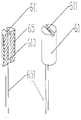
- the electronic cigarette atomizer of the ultrasonic atomizing unit of the embodiment of the present invention comprises an upper end with a suction nozzle 11 and an outer tube 1 having a lower end opening, and the outer tube 1 is sequentially provided from top to bottom.
- Liquid storage cup 2 porous branch Stretching piece 3, smoke liquid permeating sheet 4, pressing piece 5, ultrasonic atomizing unit 6, atomizing seat 7, power supply connecting seat 8; the end surface of the upper end of the atomizing seat 7 penetrates the pressing piece 5 to infiltrate the liquid smoke
- the sheet 4 is pressed against the porous support sheet 3, and the lower end of the atomizing seat 7 is connected to the power supply connector 8, and the power supply connector 8 is sleeved to the inner wall of the lower end of the outer tube 1.
- the upper end of the liquid storage cup 2 is closed and the lower end is open, and the liquid storage cup 2 is used for storing the electronic cigarette liquid.
- the porous supporting piece 3 is laterally fixed on the inner wall of the opening at the lower end of the liquid storage cup 2.
- the porous supporting piece 3 is a hard piece provided with a plurality of small through holes, and the inner wall of the liquid storage cup on which the upper and lower sides are located is provided with a hole for clamping A bump or a convex ring (not shown) of the support piece 3 is attached thereto.
- the porous support sheet 3 is provided with a plurality of small through holes for the electronic soot liquid to slowly flow out from the liquid storage cup 2, and the porous support sheet 3 simultaneously serves as a fixed support for the liquid liquid permeating sheet 4.
- the smoke liquid permeating sheet 4 is closely attached to the porous supporting sheet 3, and is generally made of a material having a porous shape and a slow penetration property. When the user smokes, a negative pressure is generated in the atomizing seat 7 to be inside the liquid storage cup 2.
- the electronic cigarette liquid permeates through the smoke liquid permeable sheet 4, and when the user does not smoke, the pressure inside and outside the liquid storage cup 2 is balanced, and the smoke liquid permeable sheet 4 can prevent the smoke liquid from leaking out from the liquid storage cup 2.
- the liquid storage cup 2 is provided with a rectangular notch 21 at the lower end side wall portion, and the outer surface of the liquid storage cup 2 is provided with a smoke in the axial direction at the same circumferential position as the rectangular notch 21.
- the groove 22, the porous support sheet 3, and the soot liquid permeating sheet 4 are disposed on the inner wall above the rectangular notch 21 of the liquid storage cup 2, and the lower plane of the soot liquid permeating sheet 4 is flush with the upper edge of the rectangular notch 21.
- the upper end of the atomizing seat 7 is sleeved on the inner wall of the liquid storage cup 2 at the position of the rectangular notch 21, and the smoke outlet of the atomizing seat 7 is disposed to coincide with the rectangular notch 21 of the liquid storage cup 2, so that the atomization unit 6 atomizes
- the electronic smoke can be discharged through the smoke outlet 71 (rectangular notch 21), and then the electronic cigarette mist passage formed by the smoke tank 22 and the inner wall of the outer tube 1 finally flows out from the suction port 111 of the suction nozzle 11 to the user's mouth. .
- the pressing piece 5 has an I-shape and can be placed in the lower end opening of the liquid storage cup 2, and the upper and lower sides are convex arc segments, and the lower side is also provided with vertical Sheet-like projections 51.
- the smoke liquid permeating sheet 4 of the present invention increases gravity when it absorbs the electronic cigarette smoke liquid. Under the action of gravity, the soft liquid smoke permeating sheet 4 easily deviates from the porous supporting sheet 3, and is loosened, so that the electronic cigarette The liquid smoke easily leaks from the liquid storage cup 2.
- a pressure piece 5 is provided, which is pressed under the upper end surface of the atomization seat 7, and the pressure piece 5 can press the smoke liquid permeating sheet 4 against the porous support piece 3, so that the smoke liquid permeation piece 4 does not Looseness occurs, preventing the electronic cigarette liquid from leaking out of the liquid storage cup 2.
- the pressing piece 5 of the present invention can be made of a thin stainless steel sheet to reduce the thickness and increase the supporting rigidity.
- the atomizing base 7 is a tubular body in which a smoke outlet 71 is opened in a side wall portion, and a built-in ultrasonic atomizing unit 6 is provided.
- the ultrasonic atomizing unit 6 includes a liquid guiding strip 61 and an atomizing sheet. 62 and the ultrasonic oscillating plate 63, the two sides of the liquid guiding strip 61 are respectively connected with the smoke liquid permeable sheet 4 and the atomizing sheet 62, and the ultrasonic oscillating sheet 63 can conduct the self-smoke liquid permeable sheet 4 and the liquid guiding strip 5 to the atomizing sheet 62.
- the electronic cigarette smoke liquid is ultrasonically atomized.
- the bottom of the atomizing seat 7 is provided with a bottom wall 72.
- the bottom wall 72 is provided with an air inlet through hole 73.
- the bottom wall 72 is provided with an air inlet groove 74 from the air inlet through hole 73 to the opposite side of the smoke outlet 71.
- the intake groove 74 continues to the inner side wall of the atomizing seat 7, and the bottom wall 72 of the atomizing seat 7 is further provided with a downward threading hole 721 for the two electrode leads 631 of the ultrasonic vibrating piece 63 to pass therethrough.
- the ultrasonic oscillating sheet 63 is disposed on the upper surface of the bottom wall 72, and the atomizing sheet 62 is disposed on the upper surface of the ultrasonic oscillating sheet 63.
- the liquid guiding strip 61 is disposed between the liquid permeable sheet 4 and the atomizing sheet 62 and both The contact connection serves to conduct the smoke liquid in the liquid permeating sheet 4 to the atomizing sheet 62.
- the liquid smoke permeating sheet 4 and the atomizing sheet 62 of the present invention are made of ceramic fibers, and the liquid guiding strip 61 is made of ceramic fiber, glass fiber or hard porous ceramic material for better absorption, conduction and storage of electronic cigarettes. Smoke liquid.
- the atomizing seat 7 is made of a silicone material, and the soft silicone material acts to absorb shock and seal.
- the atomization base 7 further includes an atomization seat cover 75 disposed at an upper end thereof, and the atomization seat cover 75 is provided with a cover hole 751 corresponding to the position of the liquid guiding strip 61, and the liquid guiding strip 61 passes through the cover hole 751.
- the atomizing seat cover 75 is used for positioning and fixing the liquid guiding strip 61 and making the atomizing seat 7 less susceptible to deformation.
- the power connector 8 includes a tubular body 81 having an annular shoulder 810 at one end. The other end of the tubular body 81 is sleeved with the electrode holder 82.
- the electrode holder 82 is provided with a thread 820 and an electrode holder.
- a radial blocking ring 821 is disposed in the middle of the blocking ring 821, and an insulating sleeve 83 is disposed in the middle through hole of the blocking ring 821.
- the insulating sleeve 83 is provided with a nail-shaped electrode 84, and an electrode through hole 841 is disposed in the middle of the nail-shaped electrode 84.
- the two electrodes of the ultrasonic oscillating plate 63 are electrically connected to the spike electrode 84 and the electrode holder 82, respectively, and are further electrically connected to the positive and negative electrodes of the electronic cigarette power source.
- the electronic cigarette liquid contained in the liquid storage cup 2 flows out through the small through hole of the porous supporting piece 3 to
- the smoke liquid permeable sheet 4 when the smoke liquid permeable sheet 4 is filled with the smoke liquid, the smoke liquid can be conducted to the liquid guiding strip 61, and then transmitted to the atomizing sheet 62 via the liquid guiding strip 61, and the atomizing sheet 62 absorbs the electronic cigarette liquid.
- the liquid smoke can be atomized; at this time, the outside air flows from the electrode through hole 841 of the nail electrode 84, and then flows into the mist through the intake through hole 73 and the intake groove 74.
- the atomization space above the atomizing sheet 62 in the base 7 can generate the electronic cigarette smoke, which can be discharged through the smoke outlet 71 (rectangular notch 21), and then enclosed by the smoke tank 22 and the inner wall of the outer tube 1.
- Electronic cigarette fog passage Finally, it flows out from the suction port 111 of the suction nozzle 11 and is sucked into the mouth by the user.
- the atomization unit is modified, and a heating wire for heating is added to the liquid guiding strip, and the rest of the structure is unchanged.
- a heating wire 64 for heating is applied to the liquid guiding strip 61.
- the heating wire 64 is in operation, only the electronic cigarette liquid flowing through the liquid guiding strip can be heated. Since different types of electronic cigarette liquids have different viscosities, when the viscosity is large, the atomization effect of the ultrasonic oscillating sheet 63 on the electronic cigarette liquid may be lowered, so that the liquid guiding strip 61 is provided with heating.
- the heating wire 64 can heat the electronic cigarette liquid flowing through the liquid guiding strip 61.
- the ultrasonic vibration sheet 63 can be improved because the viscosity thereof has been lowered.
- the atomization effect Since the heating wire 64 of the second embodiment is only used for heating, the requirement for the heating wire can be thinner and shorter, and the requirement for the energizing current is also small, and the electronic cigarette liquid is not atomized when the heating is performed. .
- the liquid guiding strip 61 of the present embodiment is a cylindrical body made of a porous and permeable ceramic material, and the heating wire 64 is wound on the outside, and the lead wire 641 is connected at both ends of the heating wire 62, and the center of the liquid guiding strip 61 is provided.
- a liquid guiding through hole 610 is disposed on the axis, and a liquid guiding groove 611 is disposed on the end surface of the upper end end.
- the heating wire 64 is wound around the outer wall of the liquid guiding strip 61, and the lead wire 641 connected to the upper end of the heating wire 64 is disposed on the guide wire.
- the liquid groove 611 is drawn downward through the liquid guiding through hole 610, and the other lead 641 is drawn downward from the outer wall of the liquid guiding strip 61.
- the atomization unit is modified, and the heating wire for heating and atomizing is added to the liquid guiding strip, and the rest of the structure is unchanged.
- a heating wire 65 for heating and atomizing is disposed on the liquid guiding strip 61.
- the heating wire 65 is in operation, a part of the electronic cigarette liquid flowing through the liquid guiding strip 61 can be atomized, and another part of the electronic cigarette is atomized.
- the smoke liquid is conducted to the atomizing sheet 62 so that the ultrasonic vibration sheet 63 atomizes it.
- the heating wire 65 and the ultrasonic oscillating plate 63 are simultaneously operated when the user smokes, so that the amount of smoke generated during one smoking can be greatly improved, and the taste of the user's smoking can be improved.
- the heating wire 65 of the third embodiment is used for heating and atomizing, the requirement for the heating wire should be thicker and longer, and the electric current is required to be larger. Part of the electronic cigarette liquid should be atomized when heated.
- the liquid guiding strip 61 of the present embodiment is a cylindrical body, which is made of a porous and permeable ceramic material, and has a liquid guiding through hole 610 on a central axis thereof, and a diameter along the upper end surface of the upper end end.
- the liquid guiding groove 611, the heating wire 65 is wound around the inside of the liquid guiding strip 61 and integrated with it, and the lead wire 651 of the heating wire 65 is exposed to the liquid guiding strip 61 and is led downward.
- the liquid guiding through hole 610 and the liquid guiding groove 611 can ventilate and better conduct the liquid smoke.
Landscapes
- Special Spraying Apparatus (AREA)
- Catching Or Destruction (AREA)
- Disinfection, Sterilisation Or Deodorisation Of Air (AREA)
Abstract
一种采用超声波雾化单元(6)的电子烟雾化器,包括外管(1)、储液杯(2)、多孔支撑片(3)、烟液渗透片(4)、超声波雾化单元(6)、雾化座(7)、电源连接座(8);雾化座(7)内置超声波雾化单元(6),超声波雾化单元(6)设于雾化座(7)内,包括导液条(61)、雾化片(62)和超声波震荡片(63),超声波震荡片(63)可将自烟液渗透片(4)、导液条(61)传导至雾化片(62)的烟液进行超声波雾化;雾化座(7)上端面将烟液渗透片(4)压紧在多孔支撑片(3)上,雾化座(7)下端与电源连接座(8)连接,电源连接座(8)套接在外管(1)下端的内壁;采用超声波雾化单元(6)对烟液雾化,避免了高温加热对导液绳、雾化座(7)等部件产生的灼伤变形,防止了高温使雾化器产生故障;同时避免高温灼烧产生焦味,从而极大改善电子烟用户吸烟口感。
Description
本发明涉及电子烟技术领域,更具体的说,本发明涉及一种采用超声波雾化单元的电子烟雾化器。
传统香烟,由于烟草的烟丝在燃烧时会产生烟焦油,在吸烟时易被吸入人体而对人体造成很大的健康危害。电子烟通常是将电子烟烟液经过电子烟雾化单元的雾化而发出烟雾供吸烟者使用,由于电子烟烟液不含有烟草中的烟焦油,故电子烟已逐渐代替香烟得到广泛使用。
现有的电子烟雾化器,为了使电子烟烟液进行雾化而变成可吸的电子烟烟雾,通常采用电热丝通电对电子烟烟液进行加热雾化的方式,由于雾化需要电热丝发出较大的热量,故在加热雾化时,雾化单元产生很高的温度,在电子烟频繁使用时,雾化单元的高温容易使导液绳、雾化座灼伤产生变形,导致雾化单元易发生故障而不能正常工作,另导液绳、雾化座高温灼伤也将产生焦味,使得用户吸烟口感下降,带来不良的吸烟体验。
本发明的目的在于提供一种采用超声波雾化单元的电子烟雾化器,该电子烟雾化器采用超声波雾化单元,利用超声波震荡原理对电子烟烟液进行雾化。
问题的解决方案
本发明的技术方案是这样实现的:该采用超声波雾化单元的电子烟雾化器,包括上端带吸嘴及下端开口的外管,所述外管内自上而下向依次设有储液杯、多孔支撑片、烟液渗透片、超声波雾化单元、雾化座、电源连接座;所述储液杯上端封闭下端开口,所述多孔支撑片横向固定在所述储液杯下端开口处的内壁,所述烟液渗透片紧贴于所述多孔支撑片下面;所述雾化座为侧壁部开设有烟雾出口的管状体,所述超声波雾化单元设于所述雾化座内,包括导液条、雾化
片和超声波震荡片,所述导液条连接所述烟液渗透片和雾化片,所述超声波震荡片可将所述雾化片上的烟液进行超声波雾化;所述雾化座上端面将所述烟液渗透片压紧在所述多孔支撑片上,所述雾化座下端与所述电源连接座连接,所述电源连接座套接在所述外管下端的内壁。
优选地,所述雾化座内部设有底壁,所述底壁中间设有进气通孔,所述底壁上自进气通孔向烟雾出口对面的方向设有进气凹槽,所述进气凹槽延续到雾化座的内侧壁上。
优选地,所述超声波震荡片设于底壁上面,所述雾化片设于所述超声波震荡片上,所述导液条设于所述烟液渗透片和所述雾化片之间并与两者抵触连接。
优选地,所述雾化座还包括其上端所设的雾化座盖,所述雾化座盖上开设有与所述导液条位置相对应的盖孔,所述导液条穿过所述盖孔。
优选地,所述导液条上还设有加温用的电热丝,所述电热丝工作时仅可对流经导液条上的电子烟烟液进行加温。
优选地,所述导液条上还设有加热雾化用的电热丝,所述电热丝工作时可对流经导液条上的部分电子烟烟液进行加热雾化。
优选地,所述多孔支撑片为设有多个小通孔的硬片,所述多孔支撑片上下两面所在的储液杯内壁上设有可以夹住所述多孔支撑片的凸点或凸环。
优选地,所述烟液渗透片与雾化座上端面之间还设有压紧片,所述压紧片呈工字形可恰好放入所述储液杯开口内,其上下两边为外凸的圆弧段,下边还设有垂直的片状凸起。
优选地,所述烟液渗透片和雾化片由陶瓷纤维制成,所述导液条由陶瓷纤维、玻璃纤维或硬体多孔陶瓷材料制成,所述雾化座由硅胶材料制成。
优选地,所述储液杯在下端侧壁部设有矩形缺口,所述储液杯外表面在与所述矩形缺口相同的周向位置轴向设有烟雾槽,所述多孔支撑片、烟液渗透片横置于所述储液杯矩形缺口位置以上的内壁,所述烟液渗透片下平面与所述矩形缺口上沿相平;所述雾化座上端套设于所述储液杯在矩形缺口位置的内壁,所述雾化座的烟雾出口正对所述储液杯的矩形缺口重合设置。
发明的有益效果
该电子烟雾化器,采用超声波雾化单元的结构,利用超声波震荡原理对电子烟烟液进行雾化,超声波雾化单元工作过程中不需要对电子烟烟液进行高温加热,避免了高温加热对导液绳、雾化座等电子烟雾化器部件产生的灼伤及产生变形,防止了频繁吸烟时因高温使雾化器产生故障;同时可避免高温灼烧产生焦味,从而极大改善电子烟用户吸烟口感,提高了用户吸烟的良好体验。
对附图的简要说明
图1为本发明实施例一的剖视图;
图2为本发明实施例一的结构分解图;
图3为本发明实施例储液杯立体结构图;
图4为本发明实施例压紧片的结构图;
图5为本发明实施例雾化座的立体结构图;
图6为本发明实施例装配雾化单元的雾化座的结构分解图;
图7为本发明实施例雾化座的底部立体视图;
图8为本发明实施例电源连接座的结构分解图;
图9为本发明实施例二的剖视图;
图10为本发明实施例二的导液条装配电热丝的立体结构与剖视图;
图11为本发明实施例三的剖视图;
图12为本发明实施例三的导液条装配电热丝的立体结构与剖视图。
实施该发明的最佳实施例
本发明下面将结合附图作进一步详述:
本发明采用超声波雾化单元的电子烟雾化器,为便于以下行文描述,如图1所示将该电子烟雾化器的吸嘴朝上竖直放置,下文所述有关其部件的“上端、下端”,均是指在该电子烟雾化器竖直放置情况下的上下方向和位置关系。
如图1、图2所示,本发明实施例采用超声波雾化单元的电子烟雾化器,包括上端带吸嘴11和下端开口的外管1,外管1内自上而下向依次设有储液杯2、多孔支
撑片3、烟液渗透片4、压紧片5、超声波雾化单元6、雾化座7、电源连接座8;雾化座7上端的端面通过贴紧压紧片5后将烟液渗透片4压紧在多孔支撑片3上,雾化座7的下端与电源连接座8连接,电源连接座8套接在外管1下端的内壁。
如图1、图2、图3所示,储液杯2的上端封闭和下端开口,储液杯2用于储存电子烟烟液。多孔支撑片3横向固定在储液杯2下端开口处的内壁上,多孔支撑片3为设有多个小通孔的硬片,其上下两面所在的储液杯内壁上设有可以夹住多孔支撑片3的凸点或凸环(图中未示)以便对其固定。多孔支撑片3上设有若干小通孔以便电子烟烟液从储液杯2中缓慢流出,多孔支撑片3同时对烟液渗透片4起到固定支撑的作用。烟液渗透片4紧贴于多孔支撑片3上,其一般由具有多孔隙、能缓慢渗透的材料制成,在用户吸烟时,雾化座7内产生负压可使储液杯2内的电子烟烟液通过烟液渗透片4渗透出来,而用户不吸烟时,储液杯2内外压力平衡,烟液渗透片4可阻止烟液从储液杯2内漏出。
如图1、图2、图3所示,储液杯2在下端侧壁部设有矩形缺口21,储液杯2的外表面在与矩形缺口21相同的周向位置轴向设有一道烟雾槽22,多孔支撑片3、烟液渗透片4横置于储液杯2的矩形缺口21位置以上的内壁,烟液渗透片4下平面与矩形缺口21的上沿相平。雾化座7的上端套设于储液杯2在矩形缺口21位置的内壁,雾化座7的烟雾出口正对储液杯2的矩形缺口21重合设置,这样经超声波雾化单元6雾化的电子烟雾即可经烟雾出口71(矩形缺口21)排出,再经烟雾槽22与外管1的内壁围合而成的电子烟出雾通道,最后从吸嘴11的吸口111流出至用户口中。
如图1、图3、图4所示,压紧片5呈工字形并可恰好放入储液杯2的下端开口内,其上下两边为外凸的圆弧段,下边还设有垂直的片状凸起51。本发明的烟液渗透片4,当其吸纳饱满了电子烟烟液时,重力增加,在重力作用下,软性的烟液渗透片4容易偏离多孔支撑片3,发生松脱,这样电子烟烟液就容易从储液杯2内发生泄漏。为此设有压紧片5,在雾化座7的上端端面压紧下,压紧片5可将烟液渗透片4压紧在多孔支撑片3上,这样烟液渗透片4就不会发生松脱,避免了电子烟烟液从储液杯2内泄漏出来。本发明的压紧片5,可采用薄不锈钢钢片制成,以减少厚度提高支撑刚性。
如图5、图6、图7所示,雾化座7为侧壁部开设有烟雾出口71的管状体、内置超声波雾化单元6,超声波雾化单元6包括导液条61、雾化片62和超声波震荡片63,导液条61两端分别连接烟液渗透片4和雾化片62,超声波震荡片63可将自烟液渗透片4、导液条5传导至雾化片62的电子烟烟液进行超声波雾化。雾化座7的内部设有底壁72,底壁72的中间设有进气通孔73,底壁72上自进气通孔73向烟雾出口71对面的方向设有进气凹槽74,进气凹槽74延续到雾化座7的内侧壁上,雾化座7的底壁72上还设有向下的穿线孔721供超声波震荡片63的两个电极引线631穿过。超声波震荡片63设于底壁72的上面,雾化片62设于超声波震荡片63的上面,导液条61有两条设于烟液渗透片4和雾化片62之间并与两者抵触连接,其作用是可将烟液渗透片4中的烟液传导至雾化片62。
本发明的烟液渗透片4和雾化片62由陶瓷纤维制成,导液条61由陶瓷纤维、玻璃纤维或硬体多孔陶瓷材料制成,用以更好地吸纳、传导、储存电子烟烟液。雾化座7由硅胶材料制成,软性的硅胶材料起到减震和密封的作用。
如图5、图6所示,雾化座7还包括其上端所设的雾化座盖75,雾化座盖75上开设有与导液条61位置相对应的盖孔751,导液条61穿过盖孔751。雾化座盖75用于定位、固定导液条61以及使雾化座7不易发生变形。
如图1、图8所示,电源连接座8包括一端设有环形凸肩810的管体81,管体81另一端内壁套接电极座82,电极座82的外国设有螺纹820,电极座82内设有一道径向阻隔环821,阻隔环821的中间通孔套设有绝缘套83,绝缘套83内套设有钉形电极84,钉形电极84的中间设有电极通孔841。超声波震荡片63的两个电极分别和钉形电极84及电极座82电性连接,并进一步和电子烟电源的正负极电连接。
如图1、图3、图6、图8所示,本发明的实施例,当雾化器工作时,储液杯2内装有的电子烟烟液经多孔支撑片3的小通孔流出至烟液渗透片4,烟液渗透片4充满烟液时,可将烟液传导给导液条61,再经导液条61传导给雾化片62,雾化片62上吸纳电子烟烟液时,经超声波震荡片63通电工作即可将烟液进行雾化;此时外界空气自钉状电极84的电极通孔841流入,再经进气通孔73、进气凹槽74流入到雾化座7内的雾化片62之上的雾化空间,产生的电子烟烟雾,即可经烟雾出口71(矩形缺口21)排出,再经烟雾槽22与外管1的内壁围合而成的电子烟出雾通道
,最后从吸嘴11的吸口111流出并被用户吸入口中。
发明实施例
实施例二
本实施例二在上述实施例一的基础上,对雾化单元进行改动,在导液条上加设有加温用的电热丝,其余结构不变。
如图9所示,导液条61上加设有加温用的电热丝64,该电热丝64工作时仅可对流经导液条上的电子烟烟液进行加温。由于不同种类的电子烟烟液具有不同的粘度,在粘度较大时,超声波震荡片63对该电子烟烟液的雾化效果就可能降低,因此在导液条61上设有加温用的电热丝64,这样即可对流经导液条61的电子烟烟液进行加温,当电子烟烟液传导至雾化片62时,因其粘度已降低,即可提高超声波震荡片63对其的雾化效果。因本实施例二的电热丝64仅用于加温,故其对电热丝的要求可以较细、较短,对通电电流要求也较小,其加温时不会使电子烟烟液雾化。
如图10所示,本实施例的导液条61为一圆柱体,采用多孔易渗透的陶瓷材料制成,外面缠绕电热丝64,电热丝62两端连接引线641,导液条61的中心轴线上设有一导液通孔610,其上端端面上沿直径设有一道导液凹槽611,电热丝64缠绕于导液条61的外壁,与电热丝64上端线头相连的引线641设于导液凹槽611内并穿过导液通孔610向下引出,另一引线641则位于导液条61的外壁向下引出。
实施例三
本实施例三在上述实施例一的基础上,对雾化单元进行改动,在导液条上加设有加热雾化用的电热丝,其余结构不变。
如图11所示,导液条61上加设有加热雾化用的电热丝65,该电热丝65工作时可对流经导液条61的部分电子烟烟液进行雾化,另一部分电子烟烟液传导至雾化片62,以便超声波震荡片63对其进行雾化。本实施例三设定电热丝65和超声波震荡片63在用户吸烟时同时工作,因此可以大大提高一次吸烟时产生的烟雾量,提升用户吸烟的口感。与实施例二不同的是,因本实施例三的电热丝65用于加热雾化,故其对电热丝的要求应当较粗、较长,对通电电流要求也较大,其
加热时应使部分电子烟烟液雾化。
如图12所示,本实施例的导液条61为一圆柱体,采用多孔易渗透的陶瓷材料制成,其中心轴线上设有一导液通孔610,其上端端面上沿直径设有一道导液凹槽611,电热丝65缠绕于导液条61的内部并与其融合制成为一体,电热丝65的引线651露出于导液条61并向下引出。导液通孔610与导液凹槽611可以通气及更好地传导烟液。
以上所述仅为本发明的较佳实施例,凡依本发明权利要求范围所做的均等变化与修饰,皆应属本发明权利要求的涵盖范围。
Claims (10)
- 一种采用超声波雾化单元的电子烟雾化器,其特征在于:包括上端带吸嘴及下端开口的外管,所述外管内自上而下向依次设有储液杯、多孔支撑片、烟液渗透片、超声波雾化单元、雾化座、电源连接座;所述储液杯上端封闭下端开口,所述多孔支撑片横向固定在所述储液杯下端开口处的内壁,所述烟液渗透片紧贴于所述多孔支撑片下面;所述雾化座为侧壁部开设有烟雾出口的管状体,所述超声波雾化单元设于所述雾化座内,包括导液条、雾化片和超声波震荡片,所述导液条连接所述烟液渗透片和雾化片,所述超声波震荡片可将所述雾化片上的烟液进行超声波雾化;所述雾化座上端面将所述烟液渗透片压紧在所述多孔支撑片上,所述雾化座下端与所述电源连接座连接,所述电源连接座套接在所述外管下端的内壁。
- 根据权利要求1所述的采用超声波雾化单元的电子烟雾化器,其特征在于:所述雾化座内部设有底壁,所述底壁中间设有进气通孔,所述底壁上自进气通孔向烟雾出口对面的方向设有进气凹槽,所述进气凹槽延续到雾化座的内侧壁上。
- 根据权利要求2所述的采用超声波雾化单元的电子烟雾化器,其特征在于:所述超声波震荡片设于所述底壁上面,所述雾化片设于所述超声波震荡片上,所述导液条设于所述烟液渗透片和所述雾化片之间并与两者抵触连接。
- 根据权利要求1所述的采用超声波雾化单元的电子烟雾化器,其特征在于:所述雾化座还包括其上端所设的雾化座盖,所述雾化座盖上开设有与所述导液条位置相对应的盖孔,所述导液条穿过所述盖孔。
- 根据权利要求1所述的采用超声波雾化单元的电子烟雾化器,其特征在于:所述导液条上还设有加温用的电热丝,所述电热丝工作时仅可对流经导液条上的电子烟烟液进行加温。
- 根据权利要求1所述的采用超声波雾化单元的电子烟雾化器,其特征在于:所述导液条上还设有加热雾化用的电热丝,所述电热丝工作时可对流经导液条上的部分电子烟烟液进行加热雾化。
- 根据权利要求1所述的采用超声波雾化单元的电子烟雾化器,其特征在于:所述多孔支撑片为设有多个小通孔的硬片,所述多孔支撑片上下两面所在的储液杯内壁上设有可以夹住所述多孔支撑片的凸点或凸环。
- 根据权利要求1所述的采用超声波雾化单元的电子烟雾化器,其特征在于:所述烟液渗透片与雾化座上端面之间还设有压紧片,所述压紧片呈工字形可恰好放入所述储液杯开口内,其上下两边为外凸的圆弧段,下边还设有垂直的片状凸起。
- 根据权利要求1所述的采用超声波雾化单元的电子烟雾化器,其特征在于:所述烟液渗透片和雾化片由陶瓷纤维制成,所述导液条由陶瓷纤维、玻璃纤维或硬体多孔陶瓷材料制成,所述雾化座由硅胶材料制成。
- 根据权利要求1所述的采用超声波雾化单元的电子烟雾化器,其特征在于:所述储液杯在下端侧壁部设有矩形缺口,所述储液杯外表面在与所述矩形缺口相同的周向位置轴向设有烟雾槽,所述多孔支撑片、烟液渗透片横置于所述储液杯矩形缺口位置以上的内壁,所述烟液渗透片下平面与所述矩形缺口上沿相平;所述雾化座上端套设于所述储液杯在矩形缺口位置的内壁,所述雾化座的烟雾出口正对所述储液杯的矩形缺口重合设置。
Priority Applications (3)
| Application Number | Priority Date | Filing Date | Title |
|---|---|---|---|
| EP17819102.9A EP3479705B1 (en) | 2016-07-01 | 2017-06-15 | Electronic cigarette atomizer using ultrasonic atomization unit |
| US16/322,245 US11369147B2 (en) | 2016-07-01 | 2017-06-15 | Electronic cigarette atomizer employing ultrasonic atomizing unit |
| PL17819102T PL3479705T3 (pl) | 2016-07-01 | 2017-06-15 | Atomizer elektronicznego papierosa z wykorzystaniem ultradźwiękowego zespołu atomizacji |
Applications Claiming Priority (2)
| Application Number | Priority Date | Filing Date | Title |
|---|---|---|---|
| CN201610518211.3A CN105962421B (zh) | 2016-07-01 | 2016-07-01 | 采用超声波雾化单元的电子烟雾化器 |
| CN201610518211.3 | 2016-07-01 |
Publications (1)
| Publication Number | Publication Date |
|---|---|
| WO2018001105A1 true WO2018001105A1 (zh) | 2018-01-04 |
Family
ID=56954747
Family Applications (1)
| Application Number | Title | Priority Date | Filing Date |
|---|---|---|---|
| PCT/CN2017/088464 WO2018001105A1 (zh) | 2016-07-01 | 2017-06-15 | 采用超声波雾化单元的电子烟雾化器 |
Country Status (5)
| Country | Link |
|---|---|
| US (1) | US11369147B2 (zh) |
| EP (1) | EP3479705B1 (zh) |
| CN (1) | CN105962421B (zh) |
| PL (1) | PL3479705T3 (zh) |
| WO (1) | WO2018001105A1 (zh) |
Cited By (8)
| Publication number | Priority date | Publication date | Assignee | Title |
|---|---|---|---|---|
| US10548349B2 (en) | 2017-07-17 | 2020-02-04 | Rai Strategic Holdings, Inc. | No heat, no-burn smoking article |
| US11096419B2 (en) | 2019-01-29 | 2021-08-24 | Rai Strategic Holdings, Inc. | Air pressure sensor for an aerosol delivery device |
| US20210345670A1 (en) * | 2018-11-29 | 2021-11-11 | Shenzhen First Union Technology Co., Ltd. | Electronic cigarette atomizer and electronic cigarette comprising same |
| US11207711B2 (en) | 2019-08-19 | 2021-12-28 | Rai Strategic Holdings, Inc. | Detachable atomization assembly for aerosol delivery device |
| US11304451B2 (en) | 2019-10-18 | 2022-04-19 | Rai Strategic Holdings, Inc. | Aerosol delivery device with dual reservoir |
| US11785991B2 (en) | 2019-10-04 | 2023-10-17 | Rai Strategic Holdings, Inc. | Use of infrared temperature detection in an aerosol delivery device |
| US11889861B2 (en) | 2019-09-23 | 2024-02-06 | Rai Strategic Holdings, Inc. | Arrangement of atomization assemblies for aerosol delivery device |
| US11969545B2 (en) | 2020-12-01 | 2024-04-30 | Rai Strategic Holdings, Inc. | Liquid feed systems for an aerosol delivery device |
Families Citing this family (22)
| Publication number | Priority date | Publication date | Assignee | Title |
|---|---|---|---|---|
| CN105962421B (zh) * | 2016-07-01 | 2018-12-25 | 林光榕 | 采用超声波雾化单元的电子烟雾化器 |
| CN106418709B (zh) * | 2016-10-10 | 2023-08-08 | 深圳市康泓威科技有限公司 | 横向供液的电子烟 |
| RU2019110647A (ru) | 2016-10-11 | 2020-10-12 | Бритиш Америкэн Тобэкко (Инвестментс) Лимитед | Система и способ предоставления аэрозоля |
| KR102253454B1 (ko) | 2016-10-20 | 2021-05-17 | 차이나 토바코 후난 인더스트리얼 코포레이션 리미티드 | 무화기 및 이를 갖는 전자 담배 |
| CN106617319A (zh) * | 2016-12-14 | 2017-05-10 | 郑州游爱网络技术有限公司 | 一种便于雾化吸入的电子烟 |
| CN110152113A (zh) * | 2018-02-05 | 2019-08-23 | 金华市坤麦科技有限公司 | 超声波输液报警器 |
| CN110122925A (zh) * | 2018-02-09 | 2019-08-16 | 湖南中烟工业有限责任公司 | 一种超声雾化电子烟用烟弹和超声雾化电子烟 |
| EP4212048A1 (en) | 2018-09-05 | 2023-07-19 | Shenzhen Smoore Technology Limited | Atomizer and electronic atomization device |
| CN117461891A (zh) * | 2018-09-05 | 2024-01-30 | 深圳麦克韦尔科技有限公司 | 雾化装置及电子烟 |
| CN109007987A (zh) * | 2018-09-29 | 2018-12-18 | 惠州市新泓威科技有限公司 | 烟液可加热的电子烟雾化器 |
| EP3850971A4 (en) * | 2018-12-18 | 2022-07-06 | China Tobacco Hunan Industrial Co., Ltd. | ATOMIZER PLATE ASSEMBLY, ATOMIZER AND ELECTRONIC CIGARETTE |
| CN110584209B (zh) * | 2019-09-06 | 2024-04-05 | 华健 | 一种超声波电子烟雾化器 |
| WO2021121357A1 (zh) * | 2019-12-20 | 2021-06-24 | 湖南中烟工业有限责任公司 | 一种导油陶瓷及超声波雾化器 |
| CN111345508A (zh) * | 2020-04-17 | 2020-06-30 | 惠州市新泓威科技有限公司 | 方便加液和组装的电子烟 |
| CN111345507A (zh) * | 2020-04-17 | 2020-06-30 | 惠州市新泓威科技有限公司 | 雾化座固定于电池组件上的电子烟 |
| CN113173801B (zh) * | 2021-04-28 | 2022-12-13 | 深圳市基克纳科技有限公司 | 一种多孔材料及其制备方法与应用 |
| CN217012766U (zh) * | 2021-05-12 | 2022-07-22 | 东莞富强电子有限公司 | 电子烟 |
| CN113907432B (zh) * | 2021-09-28 | 2024-03-22 | 深圳市真味生物科技有限公司 | 一种电子雾化装置及带有该雾化装置的电子雾化器 |
| WO2023110866A1 (en) * | 2021-12-14 | 2023-06-22 | Jt International S.A. | Aerosol generating system with improved wicking |
| CN118382377A (zh) * | 2021-12-14 | 2024-07-23 | 日本烟草国际股份公司 | 具有增强的局部热量传递和/或液体传递的气溶胶产生装置 |
| CN114668190A (zh) * | 2022-03-21 | 2022-06-28 | 惠州市新泓威科技有限公司 | 横向导液的雾化器 |
| WO2024077566A1 (zh) * | 2022-10-13 | 2024-04-18 | 深圳市华诚达精密工业有限公司 | 多通道供液的电子加热雾化装置 |
Citations (8)
| Publication number | Priority date | Publication date | Assignee | Title |
|---|---|---|---|---|
| US5331979A (en) * | 1992-07-27 | 1994-07-26 | Henley Julian L | Iontophoretic cigarette substitute |
| CN203575649U (zh) * | 2013-10-16 | 2014-05-07 | 王立平 | 一种电子烟的雾化装置 |
| CN203662023U (zh) * | 2013-12-02 | 2014-06-25 | 阚立刚 | 一种超声波雾化装置 |
| CN204180937U (zh) * | 2014-09-05 | 2015-03-04 | 深圳市施美乐科技有限公司 | 一种电子烟及电子烟雾化装置 |
| CN105266206A (zh) * | 2015-10-23 | 2016-01-27 | 上海应用技术学院 | 超声波雾化电子烟 |
| CN105962421A (zh) * | 2016-07-01 | 2016-09-28 | 林光榕 | 采用超声波雾化单元的电子烟雾化器 |
| CN205947122U (zh) * | 2016-07-01 | 2017-02-15 | 林光榕 | 采用超声波雾化单元的电子烟雾化器 |
| CN206137193U (zh) * | 2016-07-01 | 2017-05-03 | 林光榕 | 采用混合雾化单元的电子烟雾化器 |
Family Cites Families (11)
| Publication number | Priority date | Publication date | Assignee | Title |
|---|---|---|---|---|
| CN100381083C (zh) * | 2003-04-29 | 2008-04-16 | 韩力 | 一种非可燃性电子喷雾香烟 |
| CN201341435Y (zh) * | 2008-10-31 | 2009-11-11 | 柳哲琦 | 一种模拟香烟的电子烟具 |
| KR20100097807A (ko) * | 2009-02-27 | 2010-09-06 | 디엔씨엔지니어링 주식회사 | 전자담배 |
| PL2982255T3 (pl) * | 2010-08-24 | 2019-11-29 | Jt Int Sa | Urządzenie do wdychania z kontrolowanym użyciem substancji |
| JP2013230109A (ja) * | 2012-04-27 | 2013-11-14 | Sumitomo Chemical Co Ltd | 超音波霧化装置 |
| WO2015035557A1 (zh) * | 2013-09-10 | 2015-03-19 | 吉瑞高新科技股份有限公司 | 一种雾化组件和电池组件以及电子烟 |
| US20160089508A1 (en) * | 2014-09-25 | 2016-03-31 | ALTR, Inc. | Vapor inhalation device |
| CN105559151B (zh) * | 2016-03-21 | 2019-05-24 | 湖南中烟工业有限责任公司 | 一种超声波雾化器及电子烟 |
| US11786674B2 (en) * | 2018-09-06 | 2023-10-17 | Feellife Health Inc. | High-frequency ultrasonic atomizer structure |
| US11592793B2 (en) * | 2018-11-19 | 2023-02-28 | Rai Strategic Holdings, Inc. | Power control for an aerosol delivery device |
| CN111358058A (zh) * | 2018-12-26 | 2020-07-03 | 常州市派腾电子技术服务有限公司 | 电池壳及电子烟、装配方法 |
-
2016
- 2016-07-01 CN CN201610518211.3A patent/CN105962421B/zh active Active
-
2017
- 2017-06-15 EP EP17819102.9A patent/EP3479705B1/en active Active
- 2017-06-15 US US16/322,245 patent/US11369147B2/en active Active
- 2017-06-15 PL PL17819102T patent/PL3479705T3/pl unknown
- 2017-06-15 WO PCT/CN2017/088464 patent/WO2018001105A1/zh unknown
Patent Citations (8)
| Publication number | Priority date | Publication date | Assignee | Title |
|---|---|---|---|---|
| US5331979A (en) * | 1992-07-27 | 1994-07-26 | Henley Julian L | Iontophoretic cigarette substitute |
| CN203575649U (zh) * | 2013-10-16 | 2014-05-07 | 王立平 | 一种电子烟的雾化装置 |
| CN203662023U (zh) * | 2013-12-02 | 2014-06-25 | 阚立刚 | 一种超声波雾化装置 |
| CN204180937U (zh) * | 2014-09-05 | 2015-03-04 | 深圳市施美乐科技有限公司 | 一种电子烟及电子烟雾化装置 |
| CN105266206A (zh) * | 2015-10-23 | 2016-01-27 | 上海应用技术学院 | 超声波雾化电子烟 |
| CN105962421A (zh) * | 2016-07-01 | 2016-09-28 | 林光榕 | 采用超声波雾化单元的电子烟雾化器 |
| CN205947122U (zh) * | 2016-07-01 | 2017-02-15 | 林光榕 | 采用超声波雾化单元的电子烟雾化器 |
| CN206137193U (zh) * | 2016-07-01 | 2017-05-03 | 林光榕 | 采用混合雾化单元的电子烟雾化器 |
Non-Patent Citations (1)
| Title |
|---|
| See also references of EP3479705A4 * |
Cited By (13)
| Publication number | Priority date | Publication date | Assignee | Title |
|---|---|---|---|---|
| US11883579B2 (en) | 2017-07-17 | 2024-01-30 | Rai Strategic Holdings, Inc. | No-heat, no-burn smoking article |
| US10856572B2 (en) | 2017-07-17 | 2020-12-08 | Rai Strategic Holdings, Inc. | No-heat, no-burn smoking article |
| US10548349B2 (en) | 2017-07-17 | 2020-02-04 | Rai Strategic Holdings, Inc. | No heat, no-burn smoking article |
| US20210345670A1 (en) * | 2018-11-29 | 2021-11-11 | Shenzhen First Union Technology Co., Ltd. | Electronic cigarette atomizer and electronic cigarette comprising same |
| US11096419B2 (en) | 2019-01-29 | 2021-08-24 | Rai Strategic Holdings, Inc. | Air pressure sensor for an aerosol delivery device |
| US11964301B2 (en) | 2019-08-19 | 2024-04-23 | Rai Strategic Holdings, Inc. | Detachable atomization assembly for aerosol delivery device |
| US11207711B2 (en) | 2019-08-19 | 2021-12-28 | Rai Strategic Holdings, Inc. | Detachable atomization assembly for aerosol delivery device |
| US11889861B2 (en) | 2019-09-23 | 2024-02-06 | Rai Strategic Holdings, Inc. | Arrangement of atomization assemblies for aerosol delivery device |
| US11785991B2 (en) | 2019-10-04 | 2023-10-17 | Rai Strategic Holdings, Inc. | Use of infrared temperature detection in an aerosol delivery device |
| US12114710B2 (en) | 2019-10-04 | 2024-10-15 | Rai Strategic Holdings, Inc. | Use of infrared temperature detection in an aerosol delivery device |
| US11304451B2 (en) | 2019-10-18 | 2022-04-19 | Rai Strategic Holdings, Inc. | Aerosol delivery device with dual reservoir |
| US12011042B2 (en) | 2019-10-18 | 2024-06-18 | Rai Strategic Holdings, Inc. | Aerosol delivery device with dual reservoir |
| US11969545B2 (en) | 2020-12-01 | 2024-04-30 | Rai Strategic Holdings, Inc. | Liquid feed systems for an aerosol delivery device |
Also Published As
| Publication number | Publication date |
|---|---|
| US20190191781A1 (en) | 2019-06-27 |
| EP3479705A4 (en) | 2019-06-05 |
| US11369147B2 (en) | 2022-06-28 |
| EP3479705B1 (en) | 2020-10-07 |
| EP3479705A1 (en) | 2019-05-08 |
| PL3479705T3 (pl) | 2020-12-28 |
| CN105962421B (zh) | 2018-12-25 |
| CN105962421A (zh) | 2016-09-28 |
Similar Documents
| Publication | Publication Date | Title |
|---|---|---|
| WO2018001105A1 (zh) | 采用超声波雾化单元的电子烟雾化器 | |
| WO2018001106A1 (zh) | 采用混合雾化单元的电子烟雾化器 | |
| WO2018001107A1 (zh) | 采用直立式陶瓷雾化单元的电子烟雾化器 | |
| JP6765013B2 (ja) | 電子タバコ用アトマイザー | |
| WO2020244450A1 (zh) | 电子烟雾化器 | |
| JP2023160994A (ja) | 改良型の噴霧式電子たばこ | |
| CN205947122U (zh) | 采用超声波雾化单元的电子烟雾化器 | |
| WO2017206480A1 (zh) | 一种电子烟雾化器 | |
| WO2012152053A1 (zh) | 电子雾化吸入器的雾化嘴 | |
| WO2018001108A1 (zh) | 具有平行双雾化单元的电子烟雾化器 | |
| US10945455B1 (en) | Full glass atomizer | |
| WO2018019051A1 (zh) | 电子烟雾化器 | |
| WO2021088948A1 (zh) | 一种超声波雾化器 | |
| WO2015154309A1 (zh) | 电子烟的雾化结构 | |
| WO2020011115A1 (zh) | 具有一体式雾化芯的雾化器及其电子烟 | |
| WO2018001109A1 (zh) | 具有十字形双雾化单元的电子烟雾化器 | |
| JP7483041B2 (ja) | 超音波ミスト吸入器 | |
| JP2023506333A (ja) | 超音波ミスト吸入器 | |
| WO2021103756A1 (zh) | 电子雾化装置 | |
| WO2023109220A1 (zh) | 具有镂空雾化罩的雾化器 | |
| CN113287792A (zh) | 雾化器及电子雾化装置 | |
| JP7445015B2 (ja) | 超音波ミスト吸入器 | |
| WO2018195844A1 (zh) | 一种电子烟及电子烟装置 | |
| WO2024051351A1 (zh) | 用于固态烟油的电子烟雾化器 | |
| JP7480338B2 (ja) | 超音波ミスト吸入器 |
Legal Events
| Date | Code | Title | Description |
|---|---|---|---|
| 121 | Ep: the epo has been informed by wipo that ep was designated in this application |
Ref document number: 17819102 Country of ref document: EP Kind code of ref document: A1 |
|
| NENP | Non-entry into the national phase |
Ref country code: DE |
|
| ENP | Entry into the national phase |
Ref document number: 2017819102 Country of ref document: EP Effective date: 20190201 |