EP3479705B1 - Electronic cigarette atomizer using ultrasonic atomization unit - Google Patents
Electronic cigarette atomizer using ultrasonic atomization unit Download PDFInfo
- Publication number
- EP3479705B1 EP3479705B1 EP17819102.9A EP17819102A EP3479705B1 EP 3479705 B1 EP3479705 B1 EP 3479705B1 EP 17819102 A EP17819102 A EP 17819102A EP 3479705 B1 EP3479705 B1 EP 3479705B1
- Authority
- EP
- European Patent Office
- Prior art keywords
- sheet
- liquid
- atomizing
- electronic cigarette
- guiding stick
- Prior art date
- Legal status (The legal status is an assumption and is not a legal conclusion. Google has not performed a legal analysis and makes no representation as to the accuracy of the status listed.)
- Active
Links
- 239000003571 electronic cigarette Substances 0.000 title claims description 58
- 238000000889 atomisation Methods 0.000 title claims description 12
- 239000007788 liquid Substances 0.000 claims description 177
- 235000019504 cigarettes Nutrition 0.000 claims description 46
- 238000010438 heat treatment Methods 0.000 claims description 34
- 230000006835 compression Effects 0.000 claims description 16
- 238000007906 compression Methods 0.000 claims description 16
- 239000000919 ceramic Substances 0.000 claims description 7
- 238000010792 warming Methods 0.000 claims description 7
- 239000000835 fiber Substances 0.000 claims description 6
- 229910010293 ceramic material Inorganic materials 0.000 claims description 5
- 239000000463 material Substances 0.000 claims description 4
- 229920001296 polysiloxane Polymers 0.000 claims description 4
- 239000003365 glass fiber Substances 0.000 claims description 3
- 239000000779 smoke Substances 0.000 description 6
- 230000000391 smoking effect Effects 0.000 description 6
- 238000005485 electric heating Methods 0.000 description 4
- WABPQHHGFIMREM-UHFFFAOYSA-N lead(0) Chemical compound [Pb] WABPQHHGFIMREM-UHFFFAOYSA-N 0.000 description 4
- 238000010586 diagram Methods 0.000 description 3
- 230000000694 effects Effects 0.000 description 3
- SNICXCGAKADSCV-JTQLQIEISA-N (-)-Nicotine Chemical compound CN1CCC[C@H]1C1=CC=CN=C1 SNICXCGAKADSCV-JTQLQIEISA-N 0.000 description 2
- 230000000903 blocking effect Effects 0.000 description 2
- 230000005484 gravity Effects 0.000 description 2
- 230000007257 malfunction Effects 0.000 description 2
- 229960002715 nicotine Drugs 0.000 description 2
- SNICXCGAKADSCV-UHFFFAOYSA-N nicotine Natural products CN1CCCC1C1=CC=CN=C1 SNICXCGAKADSCV-UHFFFAOYSA-N 0.000 description 2
- 238000009834 vaporization Methods 0.000 description 2
- 230000008016 vaporization Effects 0.000 description 2
- 241000208125 Nicotiana Species 0.000 description 1
- 235000002637 Nicotiana tabacum Nutrition 0.000 description 1
- 238000010521 absorption reaction Methods 0.000 description 1
- 230000003247 decreasing effect Effects 0.000 description 1
- 230000002349 favourable effect Effects 0.000 description 1
- 239000000383 hazardous chemical Substances 0.000 description 1
- 231100000206 health hazard Toxicity 0.000 description 1
- 238000004519 manufacturing process Methods 0.000 description 1
- 230000004048 modification Effects 0.000 description 1
- 238000012986 modification Methods 0.000 description 1
- 239000011148 porous material Substances 0.000 description 1
- 230000035939 shock Effects 0.000 description 1
- 229910001220 stainless steel Inorganic materials 0.000 description 1
- 239000010935 stainless steel Substances 0.000 description 1
Images


Classifications
-
- A—HUMAN NECESSITIES
- A24—TOBACCO; CIGARS; CIGARETTES; SIMULATED SMOKING DEVICES; SMOKERS' REQUISITES
- A24F—SMOKERS' REQUISITES; MATCH BOXES; SIMULATED SMOKING DEVICES
- A24F40/00—Electrically operated smoking devices; Component parts thereof; Manufacture thereof; Maintenance or testing thereof; Charging means specially adapted therefor
- A24F40/40—Constructional details, e.g. connection of cartridges and battery parts
- A24F40/46—Shape or structure of electric heating means
-
- A—HUMAN NECESSITIES
- A24—TOBACCO; CIGARS; CIGARETTES; SIMULATED SMOKING DEVICES; SMOKERS' REQUISITES
- A24F—SMOKERS' REQUISITES; MATCH BOXES; SIMULATED SMOKING DEVICES
- A24F40/00—Electrically operated smoking devices; Component parts thereof; Manufacture thereof; Maintenance or testing thereof; Charging means specially adapted therefor
- A24F40/05—Devices without heating means
-
- A—HUMAN NECESSITIES
- A24—TOBACCO; CIGARS; CIGARETTES; SIMULATED SMOKING DEVICES; SMOKERS' REQUISITES
- A24F—SMOKERS' REQUISITES; MATCH BOXES; SIMULATED SMOKING DEVICES
- A24F40/00—Electrically operated smoking devices; Component parts thereof; Manufacture thereof; Maintenance or testing thereof; Charging means specially adapted therefor
- A24F40/40—Constructional details, e.g. connection of cartridges and battery parts
- A24F40/42—Cartridges or containers for inhalable precursors
-
- A—HUMAN NECESSITIES
- A24—TOBACCO; CIGARS; CIGARETTES; SIMULATED SMOKING DEVICES; SMOKERS' REQUISITES
- A24F—SMOKERS' REQUISITES; MATCH BOXES; SIMULATED SMOKING DEVICES
- A24F40/00—Electrically operated smoking devices; Component parts thereof; Manufacture thereof; Maintenance or testing thereof; Charging means specially adapted therefor
- A24F40/40—Constructional details, e.g. connection of cartridges and battery parts
- A24F40/44—Wicks
-
- B—PERFORMING OPERATIONS; TRANSPORTING
- B05—SPRAYING OR ATOMISING IN GENERAL; APPLYING FLUENT MATERIALS TO SURFACES, IN GENERAL
- B05B—SPRAYING APPARATUS; ATOMISING APPARATUS; NOZZLES
- B05B17/00—Apparatus for spraying or atomising liquids or other fluent materials, not covered by the preceding groups
- B05B17/04—Apparatus for spraying or atomising liquids or other fluent materials, not covered by the preceding groups operating with special methods
- B05B17/06—Apparatus for spraying or atomising liquids or other fluent materials, not covered by the preceding groups operating with special methods using ultrasonic or other kinds of vibrations
- B05B17/0607—Apparatus for spraying or atomising liquids or other fluent materials, not covered by the preceding groups operating with special methods using ultrasonic or other kinds of vibrations generated by electrical means, e.g. piezoelectric transducers
-
- H—ELECTRICITY
- H05—ELECTRIC TECHNIQUES NOT OTHERWISE PROVIDED FOR
- H05B—ELECTRIC HEATING; ELECTRIC LIGHT SOURCES NOT OTHERWISE PROVIDED FOR; CIRCUIT ARRANGEMENTS FOR ELECTRIC LIGHT SOURCES, IN GENERAL
- H05B3/00—Ohmic-resistance heating
-
- A—HUMAN NECESSITIES
- A24—TOBACCO; CIGARS; CIGARETTES; SIMULATED SMOKING DEVICES; SMOKERS' REQUISITES
- A24F—SMOKERS' REQUISITES; MATCH BOXES; SIMULATED SMOKING DEVICES
- A24F40/00—Electrically operated smoking devices; Component parts thereof; Manufacture thereof; Maintenance or testing thereof; Charging means specially adapted therefor
- A24F40/10—Devices using liquid inhalable precursors
-
- A—HUMAN NECESSITIES
- A24—TOBACCO; CIGARS; CIGARETTES; SIMULATED SMOKING DEVICES; SMOKERS' REQUISITES
- A24F—SMOKERS' REQUISITES; MATCH BOXES; SIMULATED SMOKING DEVICES
- A24F40/00—Electrically operated smoking devices; Component parts thereof; Manufacture thereof; Maintenance or testing thereof; Charging means specially adapted therefor
- A24F40/40—Constructional details, e.g. connection of cartridges and battery parts
- A24F40/48—Fluid transfer means, e.g. pumps
- A24F40/485—Valves; Apertures
Definitions
- the present invention relates to the technical field of electronic cigarettes and particularly relates to an electronic cigarette atomizer employing an ultrasonic ceramic atomizing unit.
- tar is produced with the burning of tobacco, which is easily inhaled during smoking, posing significant health hazards.
- Electronic cigarettes produce smoke by atomizing a cigarette liquid with an atomizing unit. As the electronic cigarette liquid does not contain any tar, electronic cigarettes are gradually used as a replacement for traditional cigarettes.
- the electric cigarette liquid is usually heated and atomized by an electric heating wire.
- the electric heating wire needs to emit a large amount of heat for atomization, the atomizing unit generates a high temperature during heating and atomization.
- the high temperature of the atomizing unit may easily cause the burning and deformation of the liquid guiding rope and the atomizing seat. As a result, a malfunction the atomizing unit is likely to occur.
- a burnt odor is produced due to the high-temperature burning of the liquid guiding rope and the atomizing seat. This will damage the taste of the cigarette and lead to unfavorable user experience.
- EP1618803A1 discloses a cigarette includes a smoke mouth integer comprised with a shell, a cell, a high frequency ionzer, nicotine solution storage and its container, control circuit, a display screen, a human contact sensor, a piezoelectric supersound atomizer, a high temperature vaporization nozzle and attachments, an electro-thermal vaporization nozzle installed in the air suction end of the shell goes through an electric control pump or a valve with a measuring chamber and a liquid storage container which contains nicotine solution and is connected to the electric control pump or a valve with a one-way flow valve, the control circuit plate has four export ends individually connected with the high frequency ionizer, electric heater, pump or valve and the display screen, a human resistence sensor and an air flow sensor are connected to the input end of the control circuit.
- the objective of the present invention is to provide an electronic cigarette atomizer employing an ultrasonic atomizing unit.
- the electronic cigarette atomizer employs an ultrasonic atomizing unit to atomize an electronic cigarette liquid by ultrasonic vibration.
- the electronic cigarette atomizer employing an ultrasonic atomizing unit, wherein it comprises an outer tube which is provided with a mouthpiece at its upper end and an opening at its lower end; a liquid storage cup, a porous supporting sheet, a cigarette liquid permeation sheet, an ultrasonic atomizing unit, an atomizing seat, and a power connector are provided in the outer tube consecutively from top to bottom; the liquid storage cup is closed at its upper end and opened at its lower end; the cigarette liquid permeation sheet is closely adhered to a lower surface of the porous supporting sheet; the atomizing seat is a tubular body with a vapor outlet provided at its side wall; an inside of the atomizing seat is provided with the ultrasonic atomizing unit, which includes a liquid guiding stick, an atomizing sheet, and an ultrasonic oscillating sheet; the liquid guiding stick connects with the cigarette liquid permeation sheet and the atomizing sheet; a cigarette liquid in the
- the inside of the atomizing seat is provided with a bottom wall, a center of the bottom wall is provided with an air inlet through hole; the bottom wall is provided with an air inlet groove in a direction from the air inlet through hole towards an opposite of the vapor outlet; the air inlet groove extends to an inner side wall of the atomizing seat.
- the ultrasonic oscillating sheet is disposed on an upper surface of the bottom wall; the atomizing sheet is provided on the ultrasonic oscillating sheet; the liquid guiding stick is disposed between the cigarette liquid permeation sheet and the atomizing sheet; the liquid guiding stick presses against and connect with the liquid permeation sheet and the atomizing sheet.
- the atomizing seat further includes an atomizing seat cover disposed at an upper end thereof; the atomizing seat cover is provided with a cover hole at a position corresponding to a position of the liquid guiding stick; the liquid guiding stick passes through the cover hole.
- a heating wire for warming is provided on the liquid guiding stick; when the heating wire is in operation, only an electronic cigarette liquid flowing through the liquid guiding stick is warmed.
- a heating wire for heating and atomization is provided on the liquid guiding stick; when the heating wire is in operation, part of an electronic cigarette liquid flowing through the liquid guiding stick is atomized.
- the porous supporting sheet is a hard sheet which is provided with a plurality of small through holes; an inner wall of the liquid storage cup at which upper and lower surfaces of the porous supporting sheet are positioned is provided with a protruding point or a protruding ring for clamping and fixing the porous supporting sheet.
- the compression sheet is provided between the cigarette liquid permeation sheet and an upper-end surface of the atomizing seat, the compression sheet is H-shaped and can be fit into an opening of the liquid storage cup; an upper side and a lower side of the compression sheet are convex arc segments, the lower side is provided with a vertical sheet-shaped projection.
- the cigarette liquid permeation sheet and the atomizing sheet are made from ceramic fiber; the liquid guiding stick is made from ceramic fiber, glass fiber or a hard porous ceramic material; the atomizing seat is made from a silicone material.
- a rectangular notch is provided at a side wall of a lower end of the liquid storage cup; an outer surface of the liquid storage cup is provided with a vapor groove in an axial direction and at a same circumferential position as the rectangular notch; the porous supporting sheet and the cigarette liquid permeation sheet are horizontally disposed at an inner wall of the liquid storage cup above the rectangular notch; a lower surface of the cigarette liquid permeation sheet levels with an upper edge of the rectangular notch; an upper end of the atomizing seat is inserted in the liquid storage cup and rests against an inner wall where the rectangular notch is positioned; the vapor outlet of the atomizing seat overlaps with the rectangular notch of the liquid storage cup.
- the electronic cigarette atomizer of the present invention employs an ultrasonic atomizing unit to atomize an electronic cigarette liquid by ultrasonic vibration.
- the ultrasonic atomizing unit does not need to heat the electronic cigarette liquid during its operation, preventing the burning and deformation of the components of the electronic cigarette atomizer including the liquid guiding rope and the atomizing seat. Any malfunction of the atomizer due to high temperature as a result of frequent smoking is prevented; the production of a burnt odor due to high-temperature burning is also prevented. As a result, the taste of the cigarette is improved, which leads to favorable user experience.
- the present invention relates to an electronic cigarette atomizer that employs an ultrasonic atomizing unit.
- the electronic cigarette atomizer is placed vertically with its suction hole facing upwards (as shown in FIG. 1 ).
- the terms "upper end”, “lower end” are used to describe the up/down directions and positional relationships of the components when the electronic cigarette atomizer is placed vertically.
- the electronic cigarette atomizer employing an ultrasonic atomizing unit of the embodiment of the present invention comprises an outer tube 1 which is provided with a mouthpiece 11 at its upper end and an opening at its lower end; a liquid storage cup 2, a porous supporting sheet 3, a cigarette liquid permeation sheet 4, a compression sheet 5, an ultrasonic atomizing unit 6, an atomizing seat 7, and a power connector 8 are provided in the outer tube 1 consecutively from top to bottom.
- the upper-end surface of the atomizing seat 7 is closely attached to the compression sheet 5 to press the cigarette liquid permeation sheet 4 against the porous supporting sheet 3.
- the lower end of the atomizing seat 7 is connected to the power connector 8; the power connector is sheathed in the lower end of the outer tube 1 and rests against an inner wall of the outer tube 1.
- the liquid storage cup 2 is closed at its upper end and opened at its lower end; the liquid storage cup 2 is used to store the electronic cigarette liquid.
- the porous supporting sheet 3 is horizontally fixed to the inner wall of the opening at the lower end of the liquid storage cup 2.
- the porous supporting sheet 3 is a hard sheet which is provided with a plurality of small through holes; the inner wall of the liquid storage cup at which the upper and lower surfaces of the porous supporting sheet 3 are positioned is provided with a protruding point or a protruding ring (not shown in drawings) for clamping and fixing the porous supporting sheet 3.
- the porous supporting sheet 3 is provided with a plurality of small through holes for the electronic cigarette liquid to slowly flow out from the liquid storage cup 2.
- the porous supporting sheet 3 also serves to fix and support the cigarette liquid permeation sheet 4.
- the cigarette liquid permeation sheet 4 is closely adhered to the porous supporting sheet 3 and is generally made from a porous material which allows slow permeation.
- negative pressure is created in the atomizing seat 7, which draws the electronic cigarette liquid contained in the liquid storage cup 2 out, permeating through the cigarette liquid permeation sheet 4.
- the cigarette liquid permeation sheet 4 prevents the cigarette liquid from leaking out of the liquid storage cup 2.
- the liquid storage cup 2 is provided with a rectangular notch 21 at the side wall of its lower end; the outer surface of the liquid storage cup 2 is provided with a vapor groove 22 in the axial direction and at the same circumferential position as the rectangular notch 21.
- the porous supporting sheet 3 and the cigarette liquid permeation sheet 4 are horizontally disposed at the inner wall of the liquid storage cup 2, above the rectangular notch 21.
- the lower surface of the cigarette liquid permeation sheet 4 levels with the upper edge of the rectangular notch 21.
- the upper end of the atomizing seat 7 is inserted in the liquid storage cup 2 and rests against an inner wall where the rectangular notch 21 is positioned; and the vapor outlet of the atomizing seat 7 overlaps with the rectangular notch 21 of the liquid storage cup 2, so that the electronic cigarette smoke produced by the ultrasonic atomizing unit 6 can be discharged through a vapor outlet 71 (rectangular notch 21).
- the vapor then passes a vapor discharge channel enclosed by the vapor groove 22 and the inner wall of the outer tube 1 and finally flows out into the user's mouth through the suction hole 111 of the mouthpiece 11.
- the compression sheet 5 is H-shaped and can be fit into the opening at the lower end of the liquid storage cup 2.
- the upper and lower sides of the compression sheet 5 are convex arc segments, and the lower side is provided with a vertical sheet-shaped projection 51.
- the pressing of the upper-end surface of the atomizing seat 7 allows the compression sheet 5 to press the cigarette liquid permeation sheet 4 against the porous support piece 3. In this way, the cigarette liquid permeation piece 4 will not loosen, the electronic cigarette liquid is prevented from leaking out of the liquid storage cup 2.
- the compression sheet 5 of the present invention can be made from a thin stainless steel sheet to reduce its thickness and increase its rigidity.
- the atomizing seat 7 is a tubular body with a vapor outlet 71 provided at its side wall.
- the inside of the atomizing seat 7 is provided with the ultrasonic atomizing unit 6.
- the ultrasonic atomizing unit 6 includes a liquid guiding stick 61, an atomizing sheet 62 and an ultrasonic oscillating sheet 63.
- the two ends of the liquid guiding stick 61 are respectively connected with the cigarette liquid permeation sheet 4 and the atomizing sheet 62.
- the electronic cigarette liquid conducted from the liquid permeation sheet 4 and the liquid guiding stick 5 to the atomizing sheet 62 can be ultrasonically atomized by the ultrasonic oscillating sheet 63.
- the inside of the atomizing seat 7 is provided with a bottom wall 72.
- the center of the bottom wall 72 is provided with an air inlet through hole 73.
- the bottom wall 72 is provided with an air inlet groove 74 in a direction from the air inlet through hole 73 towards the opposite of the vapor outlet 71; the air inlet groove 74 extends to the inner side wall of the atomizing seat 7.
- the bottom wall 72 of the atomizing seat 7 is further provided with a downward-extending wire inserting hole 721 for the two electrode leads 631 of the ultrasonic oscillating sheet 63 to pass through.
- the ultrasonic oscillating sheet 63 is disposed on the upper surface of the bottom wall 72; the atomizing sheet 62 is provided on the upper surface of the ultrasonic oscillating sheet 63.
- Two liquid guiding sticks 61 are disposed between the cigarette liquid permeation sheet 4 and the atomizing sheet 62; they press against and connect with the liquid permeation sheet 4 and the atomizing sheet 62.
- the liquid guiding sticks 61 serve to conduct the cigarette liquid in the liquid permeation sheet 4 to the atomizing sheet 62.
- the cigarette liquid permeation sheet 4 and the atomizing sheet 62 of the present invention are made from ceramic fiber.
- the liquid guiding stick 61 is made from ceramic fiber, glass fiber or a hard porous ceramic material for better absorption, conduction and storage of the electronic cigarette liquid.
- the atomizing seat 7 is made from a silicone material; the soft silicone material acts to absorb shock and seal.
- the atomizing seat 7 further includes an atomizing seat cover 75 disposed at an upper end thereof.
- the atomizing seat cover 75 is provided with a cover hole 751 at a position corresponding to the position of the liquid guiding stick 61.
- the liquid guiding stick 61 passes through the cover hole 751.
- the atomizing seat cover 75 is used for positioning and fixing the liquid guiding stick 61 and for preventing the atomizing seat 7 from deformation.
- the power connector 8 includes a tube body 81 provided with an annular shoulder 810 at one end; an electrode holder 82 is sheathed in the outer end of the tube body 81 and rests against an inner wall of the tube body 81.
- the outer surface of the electrode holder 82 is provided with a thread 820, the inside of the electrode holder 82 is provided with a radial blocking ring 821.
- An insulating holder 83 is inserted into a central through hole of the radial blocking ring 821.
- a nail electrode 84 is inserted into the insulating holder 83, the nail electrode 84 is provided with an electrode through hole 841 at a center thereof.
- the two electrodes of the ultrasonic oscillating sheet 63 are electrically connected to the nail electrode 84 and the electrode holder 82 respectively and are further electrically connected to the positive and negative electrodes of an electronic cigarette power source.
- the electronic cigarette liquid contained in the liquid storage cup 2 flows out through the small through holes of the porous supporting sheet 3 to the cigarette liquid permeation sheet 4.
- the cigarette liquid permeation sheet 4 fully absorbs the cigarette liquid, the cigarette liquid can be conducted to the liquid guiding stick 61, and then transferred to the atomizing sheet 62 via the liquid guiding stick 61.
- the electronic cigarette liquid absorbed by the atomizing sheet 62 is atomized by the electrically-powered ultrasonic oscillating piece 63.
- the outside air flows in from the electrode through hole 841 of the nail electrode 84, passes through the air inlet through hole 73, the air inlet groove 74, ultimately flows into an atomization space inside the atomizing seat 7 and above the atomizing sheet 62.
- the vapor then passes through a vapor discharge channel enclosed by the vapor groove 22 and the inner wall of outer tube 1 and finally flows into the user's mouth through a suction hole 111 of the mouthpiece 11.
- the atomization unit is modified: a heating wire for warming is provided on the liquid guiding stick; the other structures remain the same.
- a heating wire 64 for warming is provided on the liquid guiding stick 61.
- the heating wire 64 is in operation, only the electronic cigarette liquid flowing through the liquid guiding stick is warmed.
- Different types of electronic cigarette liquids have different viscosities; a high viscosity may lead to decreased atomization effect of the ultrasonic oscillating sheet 63 on the electronic cigarette liquid. Therefore, the liquid guiding stick 61 is provided with the heating wire 64 for warming the electronic cigarette liquid flowing through the liquid guiding stick 61.
- the heating wire 64 of embodiment 2 is only used for warming, it may be relatively fine and short; in addition, the electric current flowing through should be low. The electronic cigarette liquid is not atomized when the heating wire 64 performs warming.
- the liquid guiding stick 61 of the present embodiment is cylindrically shaped and is made from a porous and permeable ceramic material; the heating wire 64 winds around the outside of the liquid guiding stick 61.
- the two ends of the heating wire 62 are connected with a lead wire 641.
- a liquid guiding through hole 610 is provided at the central axis of the liquid guiding stick 61.
- a liquid guiding groove 611 is provided along the diameter of the upper-end surface of the liquid guiding stick 61.
- the heating wire 64 winds around the outer wall of the liquid guiding stick 61.
- the lead wire 641 which is connected to the upper end of the heating wire 64 is disposed in the liquid guiding groove 611 and is led downwards through the liquid guiding through hole 610.
- the other lead wire 641 is led downwards along the outer wall of the liquid guiding stick 61.
- the atomization unit is modified: a heating wire for heating and atomization is provided on the liquid guiding stick; the other structures remain the same.
- a heating wire 65 for heating and atomization is provided on the liquid guiding stick 61.
- the heating wire 65 is in operation, part of the electronic cigarette liquid flowing through the liquid guiding stick 61 is atomized, and the other part of the electronic cigarette is transferred to the atomizing sheet 62 to be atomized by the ultrasonic oscillating sheet 63.
- the heating wire 65 and the ultrasonic oscillating sheet 63 are simultaneously operated during smoking, so that the amount of smoke generated during smoking can be significantly increased, improving the user experience.
- the heating wire 65 in embodiment 3 is used for heating and atomization; therefore, the heating wire should be relatively thick and long; in addition, the electric current flowing through should be high. Part of the electronic cigarette liquid is atomized when the heating wire 64 performs heating.
- the liquid guiding stick 61 of the present embodiment is cylindrically shaped and is made from a porous and permeable ceramic material.
- a liquid guiding groove 611 is provided along the diameter of the upper-end surface of the liquid guiding stick 61.
- the heating wire 65 winds around the inside of the liquid guiding stick 61 and is fused integrally therewith.
- the lead wire 651 of the heating wire 65 projects out of the liquid guiding stick 61 and is led downwards.
- the liquid guiding through hole 610 and the liquid guiding groove 611 can be ventilated and can better conduct the smoke liquid.
Description
- The present invention relates to the technical field of electronic cigarettes and particularly relates to an electronic cigarette atomizer employing an ultrasonic ceramic atomizing unit.
- In traditional cigarette, tar is produced with the burning of tobacco, which is easily inhaled during smoking, posing significant health hazards. Electronic cigarettes produce smoke by atomizing a cigarette liquid with an atomizing unit. As the electronic cigarette liquid does not contain any tar, electronic cigarettes are gradually used as a replacement for traditional cigarettes.
- In an existing electronic cigarette atomizer, in order to atomize the electronic cigarette liquid to smokable electronic cigarette smoke, the electric cigarette liquid is usually heated and atomized by an electric heating wire. As the electric heating wire needs to emit a large amount of heat for atomization, the atomizing unit generates a high temperature during heating and atomization. When in frequent use, the high temperature of the atomizing unit may easily cause the burning and deformation of the liquid guiding rope and the atomizing seat. As a result, a malfunction the atomizing unit is likely to occur. In addition, a burnt odor is produced due to the high-temperature burning of the liquid guiding rope and the atomizing seat. This will damage the taste of the cigarette and lead to unfavorable user experience.
-
EP1618803A1 discloses a cigarette includes a smoke mouth integer comprised with a shell, a cell, a high frequency ionzer, nicotine solution storage and its container, control circuit, a display screen, a human contact sensor, a piezoelectric supersound atomizer, a high temperature vaporization nozzle and attachments, an electro-thermal vaporization nozzle installed in the air suction end of the shell goes through an electric control pump or a valve with a measuring chamber and a liquid storage container which contains nicotine solution and is connected to the electric control pump or a valve with a one-way flow valve, the control circuit plate has four export ends individually connected with the high frequency ionizer, electric heater, pump or valve and the display screen, a human resistence sensor and an air flow sensor are connected to the input end of the control circuit. - The objective of the present invention is to provide an electronic cigarette atomizer employing an ultrasonic atomizing unit. The electronic cigarette atomizer employs an ultrasonic atomizing unit to atomize an electronic cigarette liquid by ultrasonic vibration.
- The objective of the present invention is achieved by the following technical solution: the electronic cigarette atomizer employing an ultrasonic atomizing unit, wherein it comprises an outer tube which is provided with a mouthpiece at its upper end and an opening at its lower end; a liquid storage cup, a porous supporting sheet, a cigarette liquid permeation sheet, an ultrasonic atomizing unit, an atomizing seat, and a power connector are provided in the outer tube consecutively from top to bottom; the liquid storage cup is closed at its upper end and opened at its lower end; the cigarette liquid permeation sheet is closely adhered to a lower surface of the porous supporting sheet; the atomizing seat is a tubular body with a vapor outlet provided at its side wall; an inside of the atomizing seat is provided with the ultrasonic atomizing unit, which includes a liquid guiding stick, an atomizing sheet, and an ultrasonic oscillating sheet; the liquid guiding stick connects with the cigarette liquid permeation sheet and the atomizing sheet; a cigarette liquid in the atomizing sheet can be ultrasonically atomized by the ultrasonic oscillating sheet; an upper-end surface of the atomizing seat presses the compression sheet tightly against the porous supporting sheet; a lower end of the atomizing seat is connected to the power connector; the power connector is sheathed in a lower end of the outer tube and rests against an inner wall of the outer tube.
- Preferably, the inside of the atomizing seat is provided with a bottom wall, a center of the bottom wall is provided with an air inlet through hole; the bottom wall is provided with an air inlet groove in a direction from the air inlet through hole towards an opposite of the vapor outlet; the air inlet groove extends to an inner side wall of the atomizing seat.
- Preferably, the ultrasonic oscillating sheet is disposed on an upper surface of the bottom wall; the atomizing sheet is provided on the ultrasonic oscillating sheet; the liquid guiding stick is disposed between the cigarette liquid permeation sheet and the atomizing sheet; the liquid guiding stick presses against and connect with the liquid permeation sheet and the atomizing sheet.
- Preferably, the atomizing seat further includes an atomizing seat cover disposed at an upper end thereof; the atomizing seat cover is provided with a cover hole at a position corresponding to a position of the liquid guiding stick; the liquid guiding stick passes through the cover hole.
- Preferably, a heating wire for warming is provided on the liquid guiding stick; when the heating wire is in operation, only an electronic cigarette liquid flowing through the liquid guiding stick is warmed.
- Preferably, a heating wire for heating and atomization is provided on the liquid guiding stick; when the heating wire is in operation, part of an electronic cigarette liquid flowing through the liquid guiding stick is atomized.
- Preferably, the porous supporting sheet is a hard sheet which is provided with a plurality of small through holes; an inner wall of the liquid storage cup at which upper and lower surfaces of the porous supporting sheet are positioned is provided with a protruding point or a protruding ring for clamping and fixing the porous supporting sheet.
- Preferably, the compression sheet is provided between the cigarette liquid permeation sheet and an upper-end surface of the atomizing seat, the compression sheet is H-shaped and can be fit into an opening of the liquid storage cup; an upper side and a lower side of the compression sheet are convex arc segments, the lower side is provided with a vertical sheet-shaped projection.
- Preferably, the cigarette liquid permeation sheet and the atomizing sheet are made from ceramic fiber; the liquid guiding stick is made from ceramic fiber, glass fiber or a hard porous ceramic material; the atomizing seat is made from a silicone material.
- Preferably, a rectangular notch is provided at a side wall of a lower end of the liquid storage cup; an outer surface of the liquid storage cup is provided with a vapor groove in an axial direction and at a same circumferential position as the rectangular notch; the porous supporting sheet and the cigarette liquid permeation sheet are horizontally disposed at an inner wall of the liquid storage cup above the rectangular notch; a lower surface of the cigarette liquid permeation sheet levels with an upper edge of the rectangular notch; an upper end of the atomizing seat is inserted in the liquid storage cup and rests against an inner wall where the rectangular notch is positioned; the vapor outlet of the atomizing seat overlaps with the rectangular notch of the liquid storage cup.
- The electronic cigarette atomizer of the present invention employs an ultrasonic atomizing unit to atomize an electronic cigarette liquid by ultrasonic vibration. The ultrasonic atomizing unit does not need to heat the electronic cigarette liquid during its operation, preventing the burning and deformation of the components of the electronic cigarette atomizer including the liquid guiding rope and the atomizing seat. Any malfunction of the atomizer due to high temperature as a result of frequent smoking is prevented; the production of a burnt odor due to high-temperature burning is also prevented. As a result, the taste of the cigarette is improved, which leads to favorable user experience.
-
-
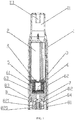
FIG. 1 is a cross-sectional view of embodiment 1 of the present invention. -
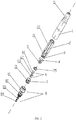
FIG. 2 is an exploded view of embodiment 1 of the present invention. -
FIG. 3 is a perspective structural diagram of a liquid storage cup according to the embodiments of the present invention. -
FIG. 4 is a structural diagram of a compression sheet according to the embodiments of the present invention. -
FIG. 5 is a perspective structural diagram of an atomizing seat according to the embodiments of the present invention. -
FIG. 6 is an exploded view of an atomizing seat assembled with an atomizing unit according to the embodiments of the present invention. -
FIG. 7 is a perspective view of the bottom of an atomizing seat according to the embodiments of the present invention. -
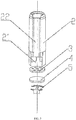
FIG. 8 is an exploded view of a power connector according to the embodiments of the present invention. -
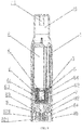
FIG. 9 is a cross-sectional view ofembodiment 2 of the present invention. -
FIG. 10 is a perspective structural view and a cross-sectional view of a liquid guiding stick assembled with an electric heating wire according toembodiment 2 of the present invention. -
FIG. 11 is a cross-sectional view of embodiment 3 of the present invention. -
FIG. 12 is a perspective structural view and a cross-sectional view of a liquid guiding stick assembled with an electric heating wire according to embodiment 3 of the present invention. - The present invention will be further described hereafter with reference to the embodiments and accompanying drawings.
- The present invention relates to an electronic cigarette atomizer that employs an ultrasonic atomizing unit. For the convenience of the following description, the electronic cigarette atomizer is placed vertically with its suction hole facing upwards (as shown in
FIG. 1 ). The terms "upper end", "lower end" are used to describe the up/down directions and positional relationships of the components when the electronic cigarette atomizer is placed vertically. - As shown in
FIG. 1 andFIG. 2 , the electronic cigarette atomizer employing an ultrasonic atomizing unit of the embodiment of the present invention comprises an outer tube 1 which is provided with amouthpiece 11 at its upper end and an opening at its lower end; aliquid storage cup 2, a porous supporting sheet 3, a cigaretteliquid permeation sheet 4, acompression sheet 5, an ultrasonic atomizingunit 6, an atomizingseat 7, and apower connector 8 are provided in the outer tube 1 consecutively from top to bottom. The upper-end surface of the atomizingseat 7 is closely attached to thecompression sheet 5 to press the cigaretteliquid permeation sheet 4 against the porous supporting sheet 3. The lower end of the atomizingseat 7 is connected to thepower connector 8; the power connector is sheathed in the lower end of the outer tube 1 and rests against an inner wall of the outer tube 1. - As shown in
FIGs. 1 ,2 , and3 , theliquid storage cup 2 is closed at its upper end and opened at its lower end; theliquid storage cup 2 is used to store the electronic cigarette liquid. The porous supporting sheet 3 is horizontally fixed to the inner wall of the opening at the lower end of theliquid storage cup 2. The porous supporting sheet 3 is a hard sheet which is provided with a plurality of small through holes; the inner wall of the liquid storage cup at which the upper and lower surfaces of the porous supporting sheet 3 are positioned is provided with a protruding point or a protruding ring (not shown in drawings) for clamping and fixing the porous supporting sheet 3. The porous supporting sheet 3 is provided with a plurality of small through holes for the electronic cigarette liquid to slowly flow out from theliquid storage cup 2. The porous supporting sheet 3 also serves to fix and support the cigaretteliquid permeation sheet 4. The cigaretteliquid permeation sheet 4 is closely adhered to the porous supporting sheet 3 and is generally made from a porous material which allows slow permeation. When the user is smoking, negative pressure is created in the atomizingseat 7, which draws the electronic cigarette liquid contained in theliquid storage cup 2 out, permeating through the cigaretteliquid permeation sheet 4. When the user is not smoking, the pressure inside and outside theliquid storage cup 2 is balanced, the cigaretteliquid permeation sheet 4 prevents the cigarette liquid from leaking out of theliquid storage cup 2. - As shown in
FIGs. 1 ,2 , and3 , theliquid storage cup 2 is provided with arectangular notch 21 at the side wall of its lower end; the outer surface of theliquid storage cup 2 is provided with avapor groove 22 in the axial direction and at the same circumferential position as therectangular notch 21. The porous supporting sheet 3 and the cigaretteliquid permeation sheet 4 are horizontally disposed at the inner wall of theliquid storage cup 2, above therectangular notch 21. The lower surface of the cigaretteliquid permeation sheet 4 levels with the upper edge of therectangular notch 21. The upper end of the atomizingseat 7 is inserted in theliquid storage cup 2 and rests against an inner wall where therectangular notch 21 is positioned; and the vapor outlet of the atomizingseat 7 overlaps with therectangular notch 21 of theliquid storage cup 2, so that the electronic cigarette smoke produced by the ultrasonic atomizingunit 6 can be discharged through a vapor outlet 71 (rectangular notch 21). The vapor then passes a vapor discharge channel enclosed by thevapor groove 22 and the inner wall of the outer tube 1 and finally flows out into the user's mouth through thesuction hole 111 of themouthpiece 11. - As shown in
FIGs. 1 ,3 and4 , thecompression sheet 5 is H-shaped and can be fit into the opening at the lower end of theliquid storage cup 2. The upper and lower sides of thecompression sheet 5 are convex arc segments, and the lower side is provided with a vertical sheet-shapedprojection 51. When the cigaretteliquid permeation sheet 4 of the present invention fully absorbs the electronic cigarette liquid, the force of gravity increases. Under the action of gravity, the soft cigaretteliquid permeation sheet 4 is prone to deviate from the porous supporting sheet 3 and loosen; as a result, the electronic cigarette liquid is very likely to leak from theliquid storage cup 2. In view of this, acompression sheet 5 is provided. The pressing of the upper-end surface of theatomizing seat 7 allows thecompression sheet 5 to press the cigaretteliquid permeation sheet 4 against the porous support piece 3. In this way, the cigaretteliquid permeation piece 4 will not loosen, the electronic cigarette liquid is prevented from leaking out of theliquid storage cup 2. Thecompression sheet 5 of the present invention can be made from a thin stainless steel sheet to reduce its thickness and increase its rigidity. - As shown in
FIGs. 5 ,6 , and7 , the atomizingseat 7 is a tubular body with avapor outlet 71 provided at its side wall. The inside of theatomizing seat 7 is provided with theultrasonic atomizing unit 6. Theultrasonic atomizing unit 6 includes aliquid guiding stick 61, anatomizing sheet 62 and anultrasonic oscillating sheet 63. The two ends of theliquid guiding stick 61 are respectively connected with the cigaretteliquid permeation sheet 4 and theatomizing sheet 62. The electronic cigarette liquid conducted from theliquid permeation sheet 4 and theliquid guiding stick 5 to theatomizing sheet 62 can be ultrasonically atomized by the ultrasonic oscillatingsheet 63. The inside of theatomizing seat 7 is provided with abottom wall 72. The center of thebottom wall 72 is provided with an air inlet throughhole 73. Thebottom wall 72 is provided with anair inlet groove 74 in a direction from the air inlet throughhole 73 towards the opposite of thevapor outlet 71; theair inlet groove 74 extends to the inner side wall of theatomizing seat 7. Thebottom wall 72 of theatomizing seat 7 is further provided with a downward-extendingwire inserting hole 721 for the two electrode leads 631 of the ultrasonic oscillatingsheet 63 to pass through. Theultrasonic oscillating sheet 63 is disposed on the upper surface of thebottom wall 72; theatomizing sheet 62 is provided on the upper surface of the ultrasonic oscillatingsheet 63. Two liquid guiding sticks 61 are disposed between the cigaretteliquid permeation sheet 4 and theatomizing sheet 62; they press against and connect with theliquid permeation sheet 4 and theatomizing sheet 62. The liquid guiding sticks 61 serve to conduct the cigarette liquid in theliquid permeation sheet 4 to theatomizing sheet 62. - The cigarette
liquid permeation sheet 4 and theatomizing sheet 62 of the present invention are made from ceramic fiber. Theliquid guiding stick 61 is made from ceramic fiber, glass fiber or a hard porous ceramic material for better absorption, conduction and storage of the electronic cigarette liquid. The atomizingseat 7 is made from a silicone material; the soft silicone material acts to absorb shock and seal. - As shown in
FIGs. 5 and6 , the atomizingseat 7 further includes an atomizing seat cover 75 disposed at an upper end thereof. The atomizingseat cover 75 is provided with acover hole 751 at a position corresponding to the position of theliquid guiding stick 61. Theliquid guiding stick 61 passes through thecover hole 751. The atomizingseat cover 75 is used for positioning and fixing theliquid guiding stick 61 and for preventing theatomizing seat 7 from deformation. - As shown in
FIG. 1 andFIG. 8 , thepower connector 8 includes atube body 81 provided with anannular shoulder 810 at one end; anelectrode holder 82 is sheathed in the outer end of thetube body 81 and rests against an inner wall of thetube body 81. The outer surface of theelectrode holder 82 is provided with athread 820, the inside of theelectrode holder 82 is provided with aradial blocking ring 821. An insulatingholder 83 is inserted into a central through hole of theradial blocking ring 821. Anail electrode 84 is inserted into the insulatingholder 83, thenail electrode 84 is provided with an electrode throughhole 841 at a center thereof. The two electrodes of the ultrasonic oscillatingsheet 63 are electrically connected to thenail electrode 84 and theelectrode holder 82 respectively and are further electrically connected to the positive and negative electrodes of an electronic cigarette power source. - As shown in
FIGs. 1 ,3 ,6 and8 , in the embodiment of the present invention, when the atomizer is operating, the electronic cigarette liquid contained in theliquid storage cup 2 flows out through the small through holes of the porous supporting sheet 3 to the cigaretteliquid permeation sheet 4. When the cigaretteliquid permeation sheet 4 fully absorbs the cigarette liquid, the cigarette liquid can be conducted to theliquid guiding stick 61, and then transferred to theatomizing sheet 62 via theliquid guiding stick 61. The electronic cigarette liquid absorbed by theatomizing sheet 62 is atomized by the electrically-powered ultrasonicoscillating piece 63. At this point, the outside air flows in from the electrode throughhole 841 of thenail electrode 84, passes through the air inlet throughhole 73, theair inlet groove 74, ultimately flows into an atomization space inside the atomizingseat 7 and above theatomizing sheet 62. The vapor then passes through a vapor discharge channel enclosed by thevapor groove 22 and the inner wall of outer tube 1 and finally flows into the user's mouth through asuction hole 111 of themouthpiece 11. - On the basis of the first embodiment described above, the atomization unit is modified: a heating wire for warming is provided on the liquid guiding stick; the other structures remain the same.
- As shown in
FIG. 9 , aheating wire 64 for warming is provided on theliquid guiding stick 61. When theheating wire 64 is in operation, only the electronic cigarette liquid flowing through the liquid guiding stick is warmed. Different types of electronic cigarette liquids have different viscosities; a high viscosity may lead to decreased atomization effect of the ultrasonic oscillatingsheet 63 on the electronic cigarette liquid. Therefore, theliquid guiding stick 61 is provided with theheating wire 64 for warming the electronic cigarette liquid flowing through theliquid guiding stick 61. When the electronic cigarette liquid is transferred to theatomizing sheet 62, the atomizing effect of theultrasonic vibration sheet 63 on the electronic cigarette liquid can be improved because the viscosity of the electronic cigarette liquid has been lowered. As theheating wire 64 ofembodiment 2 is only used for warming, it may be relatively fine and short; in addition, the electric current flowing through should be low. The electronic cigarette liquid is not atomized when theheating wire 64 performs warming. - As shown in
FIG. 10 , theliquid guiding stick 61 of the present embodiment is cylindrically shaped and is made from a porous and permeable ceramic material; theheating wire 64 winds around the outside of theliquid guiding stick 61. The two ends of theheating wire 62 are connected with alead wire 641. A liquid guiding throughhole 610 is provided at the central axis of theliquid guiding stick 61. Aliquid guiding groove 611 is provided along the diameter of the upper-end surface of theliquid guiding stick 61. Theheating wire 64 winds around the outer wall of theliquid guiding stick 61. Thelead wire 641 which is connected to the upper end of theheating wire 64 is disposed in theliquid guiding groove 611 and is led downwards through the liquid guiding throughhole 610. Theother lead wire 641 is led downwards along the outer wall of theliquid guiding stick 61. - In embodiment 3, on the basis of the first embodiment described above, the atomization unit is modified: a heating wire for heating and atomization is provided on the liquid guiding stick; the other structures remain the same.
- As shown in
FIG. 11 , aheating wire 65 for heating and atomization is provided on theliquid guiding stick 61. When theheating wire 65 is in operation, part of the electronic cigarette liquid flowing through theliquid guiding stick 61 is atomized, and the other part of the electronic cigarette is transferred to theatomizing sheet 62 to be atomized by the ultrasonic oscillatingsheet 63. In the present embodiment 3, theheating wire 65 and the ultrasonic oscillatingsheet 63 are simultaneously operated during smoking, so that the amount of smoke generated during smoking can be significantly increased, improving the user experience. What is different fromembodiment 2 is that theheating wire 65 in embodiment 3 is used for heating and atomization; therefore, the heating wire should be relatively thick and long; in addition, the electric current flowing through should be high. Part of the electronic cigarette liquid is atomized when theheating wire 64 performs heating. - As shown in
FIG. 12 , theliquid guiding stick 61 of the present embodiment is cylindrically shaped and is made from a porous and permeable ceramic material. Aliquid guiding groove 611 is provided along the diameter of the upper-end surface of theliquid guiding stick 61. Theheating wire 65 winds around the inside of theliquid guiding stick 61 and is fused integrally therewith. Thelead wire 651 of theheating wire 65 projects out of theliquid guiding stick 61 and is led downwards. The liquid guiding throughhole 610 and theliquid guiding groove 611 can be ventilated and can better conduct the smoke liquid. - The aforementioned embodiments are only the preferred embodiments of the present invention. All equivalent changes and modifications made within the scope of the claims of the present invention should fall within the scope of protection of the claims of the present invention.
Claims (10)
- An electronic cigarette atomizer employing an ultrasonic atomizing unit comprising an outer tube (1) which is provided with a mouthpiece (11) at its upper end and an opening at its lower end; a liquid storage cup (2), a porous supporting sheet (3), a cigarette liquid permeation sheet (4), an ultrasonic atomizing unit (6), an atomizing seat (7), and a power connector (8) are provided in the outer tube (1) consecutively from top to bottom; the liquid storage cup (2) is closed at its upper end and opened at its lower end; the cigarette liquid permeation sheet (4) is closely adhered to a lower surface of the porous supporting sheet (3); the atomizing seat (7) is a tubular body with a vapor outlet (71) provided at its side wall; characterized in that an inside of the atomizing seat (7) is provided with the ultrasonic atomizing unit (6), which includes a liquid guiding stick (61), an atomizing sheet (62), and an ultrasonic oscillating sheet (63); the liquid guiding stick (61) connects with the cigarette liquid permeation sheet (4) and the atomizing sheet (62); a cigarette liquid in the atomizing sheet (62) can be ultrasonically atomized by the ultrasonic oscillating sheet (63); an upper-end surface of the atomizing seat (7) presses a compression sheet (5) tightly against the porous supporting sheet (3); a lower end of the atomizing seat (7) is connected to the power connector (8); the power connector (8) is sheathed in a lower end of the outer tube (1) and rests against an inner wall of the outer tube (1).
- The electronic cigarette atomizer according to claim 1, characterized in that the inside of the atomizing seat (7) is provided with a bottom wall (72), a center of the bottom wall (72) is provided with an air inlet through hole (73); the bottom wall (72) is provided with an air inlet groove (74) in a direction from the air inlet through hole (73) towards an opposite of the vapor outlet (71); the air inlet groove (74) extends to an inner side wall of the atomizing seat (7).
- The electronic cigarette atomizer according to claim 2, characterized in that the ultrasonic oscillating sheet (63) is disposed on an upper surface of the bottom wall (72); the atomizing sheet (62) is provided on the ultrasonic oscillating sheet (63); the liquid guiding stick (61) is disposed between the cigarette liquid permeation sheet (4) and the atomizing sheet (62), the liquid guiding stick (61) presses against and connect with the liquid permeation sheet (4) and the atomizing sheet (62).
- The electronic cigarette atomizer according to claim 1, characterized in that the atomizing seat (7) further includes an atomizing seat cover (75) disposed at an upper end thereof; the atomizing seat cover (75) is provided with a cover hole (751) at a position corresponding to a position of the liquid guiding stick (61); the liquid guiding stick (61) passes through the cover hole (751).
- The electronic cigarette atomizer according to claim 1, characterized in that a heating wire (64) for warming is provided on the liquid guiding stick (61); when the heating wire (64) is in operation, only an electronic cigarette liquid flowing through the liquid guiding stick (61) is heated.
- The electronic cigarette atomizer according to claim 1, characterized in that a heating wire (64) for heating and atomization is provided on the liquid guiding stick (61); when the heating wire (64) is in operation, part of an electronic cigarette liquid flowing through the liquid guiding stick (61) is atomized.
- The electronic cigarette atomizer according to claim 1, characterized in that the porous supporting sheet (3) is a hard sheet which is provided with a plurality of small through holes; an inner wall of the liquid storage cup (2) at which upper and lower surfaces of the porous supporting sheet (3) are positioned is provided with a protruding point or a protruding ring for clamping and fixing the porous supporting sheet (3).
- The electronic cigarette atomizer according to claim 1, characterized in that the compression sheet (5) is provided between the cigarette liquid permeation sheet (4) and an upper-end surface of the atomizing seat (7), the compression sheet (5) is H-shaped and can be fit into an opening of the liquid storage cup (2); an upper side and a lower side of the compression sheet (5) are convex arc segments, the lower side is provided with a vertical sheet-shaped projection (51).
- The electronic cigarette atomizer according to claim 1, characterized in that the cigarette liquid permeation sheet (4) and the atomizing sheet (62) are made from ceramic fiber; the liquid guiding stick (61) is made from ceramic fiber, glass fiber or a hard porous ceramic material; the atomizing seat (7) is made from a silicone material.
- The electronic cigarette atomizer according to claim 1, characterized in that a rectangular notch (21) is provided at a side wall of a lower end of the liquid storage cup (2); an outer surface of the liquid storage cup (2) is provided with a vapor groove (22) in an axial direction and at a same circumferential position as the rectangular notch (21); the porous supporting sheet (3) and the cigarette liquid permeation sheet (4) are horizontally disposed at an inner wall of the liquid storage cup (2) above the rectangular notch (21); a lower surface of the cigarette liquid permeation sheet (4) levels with an upper edge of the rectangular notch (21); an upper end of the atomizing seat (7) is inserted in the liquid storage cup and rests against an inner wall where the rectangular notch (21) is positioned; the vapor outlet (71) of the atomizing seat (7) overlaps with the rectangular notch (21) of the liquid storage cup (2).
Priority Applications (1)
| Application Number | Priority Date | Filing Date | Title |
|---|---|---|---|
| PL17819102T PL3479705T3 (en) | 2016-07-01 | 2017-06-15 | Electronic cigarette atomizer using ultrasonic atomization unit |
Applications Claiming Priority (2)
| Application Number | Priority Date | Filing Date | Title |
|---|---|---|---|
| CN201610518211.3A CN105962421B (en) | 2016-07-01 | 2016-07-01 | Using the electronic smoke atomizer of ultrasonic atomization unit |
| PCT/CN2017/088464 WO2018001105A1 (en) | 2016-07-01 | 2017-06-15 | Electronic cigarette atomizer using ultrasonic atomization unit |
Publications (3)
| Publication Number | Publication Date |
|---|---|
| EP3479705A1 EP3479705A1 (en) | 2019-05-08 |
| EP3479705A4 EP3479705A4 (en) | 2019-06-05 |
| EP3479705B1 true EP3479705B1 (en) | 2020-10-07 |
Family
ID=56954747
Family Applications (1)
| Application Number | Title | Priority Date | Filing Date |
|---|---|---|---|
| EP17819102.9A Active EP3479705B1 (en) | 2016-07-01 | 2017-06-15 | Electronic cigarette atomizer using ultrasonic atomization unit |
Country Status (5)
| Country | Link |
|---|---|
| US (1) | US11369147B2 (en) |
| EP (1) | EP3479705B1 (en) |
| CN (1) | CN105962421B (en) |
| PL (1) | PL3479705T3 (en) |
| WO (1) | WO2018001105A1 (en) |
Families Citing this family (27)
| Publication number | Priority date | Publication date | Assignee | Title |
|---|---|---|---|---|
| CN105962421B (en) * | 2016-07-01 | 2018-12-25 | 林光榕 | Using the electronic smoke atomizer of ultrasonic atomization unit |
| CN106418709B (en) * | 2016-10-10 | 2023-08-08 | 深圳市康泓威科技有限公司 | Electronic cigarette with transverse liquid supply |
| RU2711673C1 (en) | 2016-10-11 | 2020-01-21 | Бритиш Америкэн Тобэкко (Инвестментс) Лимитед | Aerosol delivery system and method |
| EP3513668A4 (en) * | 2016-10-20 | 2020-05-27 | China Tobacco Hunan Industrial Co., Ltd. | Atomizer and electronic cigarette having same |
| CN106617319A (en) * | 2016-12-14 | 2017-05-10 | 郑州游爱网络技术有限公司 | Electronic cigarette convenient for aerosol inhalation |
| US10349674B2 (en) | 2017-07-17 | 2019-07-16 | Rai Strategic Holdings, Inc. | No-heat, no-burn smoking article |
| CN110152113A (en) * | 2018-02-05 | 2019-08-23 | 金华市坤麦科技有限公司 | Ultrasonic transfusion alarm |
| CN110122925A (en) * | 2018-02-09 | 2019-08-16 | 湖南中烟工业有限责任公司 | A kind of ultrasonic atomizatio electronic cigarette smoke grenade and ultrasonic atomizatio electronic cigarette |
| CN117461891A (en) * | 2018-09-05 | 2024-01-30 | 深圳麦克韦尔科技有限公司 | Atomizing device and electronic cigarette |
| CN109007987A (en) * | 2018-09-29 | 2018-12-18 | 惠州市新泓威科技有限公司 | The heatable electronic smoke atomizer of tobacco juice |
| CN209376696U (en) * | 2018-11-29 | 2019-09-13 | 深圳市合元科技有限公司 | Electronic smoke atomizer and electronic cigarette comprising the electronic smoke atomizer |
| EP3850971A4 (en) * | 2018-12-18 | 2022-07-06 | China Tobacco Hunan Industrial Co., Ltd. | Atomising plate assembly, atomiser, and electronic cigarette |
| US11096419B2 (en) | 2019-01-29 | 2021-08-24 | Rai Strategic Holdings, Inc. | Air pressure sensor for an aerosol delivery device |
| US11207711B2 (en) | 2019-08-19 | 2021-12-28 | Rai Strategic Holdings, Inc. | Detachable atomization assembly for aerosol delivery device |
| CN110584209B (en) * | 2019-09-06 | 2024-04-05 | 华健 | Ultrasonic electronic cigarette atomizer |
| US11889861B2 (en) | 2019-09-23 | 2024-02-06 | Rai Strategic Holdings, Inc. | Arrangement of atomization assemblies for aerosol delivery device |
| US11785991B2 (en) | 2019-10-04 | 2023-10-17 | Rai Strategic Holdings, Inc. | Use of infrared temperature detection in an aerosol delivery device |
| US11304451B2 (en) | 2019-10-18 | 2022-04-19 | Rai Strategic Holdings, Inc. | Aerosol delivery device with dual reservoir |
| WO2021121357A1 (en) * | 2019-12-20 | 2021-06-24 | 湖南中烟工业有限责任公司 | Oil guide ceramic and ultrasonic atomizer |
| CN111345507A (en) * | 2020-04-17 | 2020-06-30 | 惠州市新泓威科技有限公司 | Electronic cigarette with atomization seat fixed on battery pack |
| CN111345508A (en) * | 2020-04-17 | 2020-06-30 | 惠州市新泓威科技有限公司 | Electronic cigarette convenient for liquid adding and assembling |
| CN113173801B (en) * | 2021-04-28 | 2022-12-13 | 深圳市基克纳科技有限公司 | Porous material and preparation method and application thereof |
| CN113907432B (en) * | 2021-09-28 | 2024-03-22 | 深圳市真味生物科技有限公司 | Electronic atomization device and electronic atomizer with same |
| WO2023110866A1 (en) * | 2021-12-14 | 2023-06-22 | Jt International S.A. | Aerosol generating system with improved wicking |
| WO2023110760A1 (en) * | 2021-12-14 | 2023-06-22 | Jt International S.A. | Aerosol generating device with enhanced local heat and/or liquid transfer |
| CN114668190A (en) * | 2022-03-21 | 2022-06-28 | 惠州市新泓威科技有限公司 | Atomizer capable of transversely guiding liquid |
| WO2024077566A1 (en) * | 2022-10-13 | 2024-04-18 | 深圳市华诚达精密工业有限公司 | Electronic heating atomization apparatus capable of supplying liquid via multiple channels |
Family Cites Families (19)
| Publication number | Priority date | Publication date | Assignee | Title |
|---|---|---|---|---|
| US5331979A (en) * | 1992-07-27 | 1994-07-26 | Henley Julian L | Iontophoretic cigarette substitute |
| CN100381083C (en) * | 2003-04-29 | 2008-04-16 | 韩力 | Electronic nonflammable spraying cigarette |
| CN201341435Y (en) * | 2008-10-31 | 2009-11-11 | 柳哲琦 | Electronic smoking set for simulating cigarettes |
| KR20100097807A (en) * | 2009-02-27 | 2010-09-06 | 디엔씨엔지니어링 주식회사 | Electronic cigar |
| PL2982255T3 (en) * | 2010-08-24 | 2019-11-29 | Jt Int Sa | Inhalation device including substance usage controls |
| JP2013230109A (en) * | 2012-04-27 | 2013-11-14 | Sumitomo Chemical Co Ltd | Ultrasonic atomization device |
| WO2015035557A1 (en) * | 2013-09-10 | 2015-03-19 | 吉瑞高新科技股份有限公司 | Atomization assembly, battery assembly and electronic cigarette |
| CN203575649U (en) * | 2013-10-16 | 2014-05-07 | 王立平 | Atomization device of electronic cigarette |
| CN203662023U (en) * | 2013-12-02 | 2014-06-25 | 阚立刚 | Ultrasonic atomization device |
| CN204180937U (en) | 2014-09-05 | 2015-03-04 | 深圳市施美乐科技有限公司 | A kind of electronic cigarette and electronic cigarette atomization device |
| US20160089508A1 (en) * | 2014-09-25 | 2016-03-31 | ALTR, Inc. | Vapor inhalation device |
| CN105266206B (en) * | 2015-10-23 | 2018-06-29 | 上海应用技术学院 | Ultrasonic atomization electronic cigarette |
| CN105559151B (en) * | 2016-03-21 | 2019-05-24 | 湖南中烟工业有限责任公司 | A kind of ultrasonic ultrasonic delay line memory and electronic cigarette |
| CN205947122U (en) * | 2016-07-01 | 2017-02-15 | 林光榕 | Adopt electron smog spinning disk atomiser of ultrasonic atomization unit |
| CN206137193U (en) | 2016-07-01 | 2017-05-03 | 林光榕 | Adopt electron smog spinning disk atomiser that mixes atomization unit |
| CN105962421B (en) * | 2016-07-01 | 2018-12-25 | 林光榕 | Using the electronic smoke atomizer of ultrasonic atomization unit |
| US11786674B2 (en) * | 2018-09-06 | 2023-10-17 | Feellife Health Inc. | High-frequency ultrasonic atomizer structure |
| US11592793B2 (en) * | 2018-11-19 | 2023-02-28 | Rai Strategic Holdings, Inc. | Power control for an aerosol delivery device |
| CN111358058A (en) * | 2018-12-26 | 2020-07-03 | 常州市派腾电子技术服务有限公司 | Battery case, electronic cigarette and assembling method |
-
2016
- 2016-07-01 CN CN201610518211.3A patent/CN105962421B/en active Active
-
2017
- 2017-06-15 US US16/322,245 patent/US11369147B2/en active Active
- 2017-06-15 WO PCT/CN2017/088464 patent/WO2018001105A1/en unknown
- 2017-06-15 EP EP17819102.9A patent/EP3479705B1/en active Active
- 2017-06-15 PL PL17819102T patent/PL3479705T3/en unknown
Non-Patent Citations (1)
| Title |
|---|
| None * |
Also Published As
| Publication number | Publication date |
|---|---|
| EP3479705A1 (en) | 2019-05-08 |
| CN105962421A (en) | 2016-09-28 |
| CN105962421B (en) | 2018-12-25 |
| US20190191781A1 (en) | 2019-06-27 |
| PL3479705T3 (en) | 2020-12-28 |
| EP3479705A4 (en) | 2019-06-05 |
| WO2018001105A1 (en) | 2018-01-04 |
| US11369147B2 (en) | 2022-06-28 |
Similar Documents
| Publication | Publication Date | Title |
|---|---|---|
| EP3479705B1 (en) | Electronic cigarette atomizer using ultrasonic atomization unit | |
| US11707091B2 (en) | Atomizing nozzle and electronic atomizing inhaler | |
| US10980284B2 (en) | Electronic cigarette atomizer employing vertical ceramic atomizing unit | |
| WO2018001106A1 (en) | Electronic cigarette atomizer using mixed atomization unit | |
| JP6765013B2 (en) | Atomizer for electronic cigarettes | |
| EP3571943B1 (en) | Electronic cigarette | |
| CN105919164B (en) | Atomising head, atomizer and electronic cigarette | |
| US10603459B2 (en) | Variable viscosity vaporizer cartridge | |
| EP3539396B1 (en) | Electronic cigarette atomizer having widening smoke outlet tube | |
| CN106490686A (en) | Smoke creating device, electronic cigarette and the detachable atomising device that installs | |
| KR20190026929A (en) | Non-condensing flavor aspirator | |
| EP3319466A1 (en) | Wickless vaporizing devices and methods | |
| CN205947122U (en) | Adopt electron smog spinning disk atomiser of ultrasonic atomization unit | |
| CA3134178A1 (en) | Electronic cigarette vaporizer | |
| US10362805B2 (en) | Wickless cartomizer | |
| KR101315296B1 (en) | Electronic tobacco | |
| US11116253B2 (en) | Inner core element for use with electronic cigarette | |
| WO2023109220A1 (en) | Atomizer having hollowed-out atomization cover | |
| JP2019129759A (en) | Cartridge for sucker, sucker having the cartridge, and aerosol generation method | |
| WO2021018215A1 (en) | Atomizer and electronic cigarette | |
| CN206137192U (en) | Adopt vertical type pottery atomization unit's electron smog spinning disk atomiser | |
| JP2023506334A (en) | ultrasonic mist inhaler | |
| WO2022161014A1 (en) | Atomizing core having open atomizing cavity | |
| WO2022161033A1 (en) | Atomizing core having bottom atomizing cavity | |
| CN216821779U (en) | Atomizer |
Legal Events
| Date | Code | Title | Description |
|---|---|---|---|
| STAA | Information on the status of an ep patent application or granted ep patent |
Free format text: STATUS: THE INTERNATIONAL PUBLICATION HAS BEEN MADE |
|
| PUAI | Public reference made under article 153(3) epc to a published international application that has entered the european phase |
Free format text: ORIGINAL CODE: 0009012 |
|
| STAA | Information on the status of an ep patent application or granted ep patent |
Free format text: STATUS: REQUEST FOR EXAMINATION WAS MADE |
|
| 17P | Request for examination filed |
Effective date: 20190201 |
|
| AK | Designated contracting states |
Kind code of ref document: A1 Designated state(s): AL AT BE BG CH CY CZ DE DK EE ES FI FR GB GR HR HU IE IS IT LI LT LU LV MC MK MT NL NO PL PT RO RS SE SI SK SM TR |
|
| AX | Request for extension of the european patent |
Extension state: BA ME |
|
| A4 | Supplementary search report drawn up and despatched |
Effective date: 20190507 |
|
| RIC1 | Information provided on ipc code assigned before grant |
Ipc: A24F 47/00 20060101AFI20190430BHEP |
|
| DAV | Request for validation of the european patent (deleted) | ||
| DAX | Request for extension of the european patent (deleted) | ||
| REG | Reference to a national code |
Ref country code: DE Ref legal event code: R079 Ref document number: 602017025187 Country of ref document: DE Free format text: PREVIOUS MAIN CLASS: A24F0047000000 Ipc: A24F0040050000 |
|
| GRAP | Despatch of communication of intention to grant a patent |
Free format text: ORIGINAL CODE: EPIDOSNIGR1 |
|
| STAA | Information on the status of an ep patent application or granted ep patent |
Free format text: STATUS: GRANT OF PATENT IS INTENDED |
|
| RIC1 | Information provided on ipc code assigned before grant |
Ipc: A24F 40/05 20200101AFI20200408BHEP |
|
| INTG | Intention to grant announced |
Effective date: 20200430 |
|
| GRAS | Grant fee paid |
Free format text: ORIGINAL CODE: EPIDOSNIGR3 |
|
| GRAA | (expected) grant |
Free format text: ORIGINAL CODE: 0009210 |
|
| STAA | Information on the status of an ep patent application or granted ep patent |
Free format text: STATUS: THE PATENT HAS BEEN GRANTED |
|
| AK | Designated contracting states |
Kind code of ref document: B1 Designated state(s): AL AT BE BG CH CY CZ DE DK EE ES FI FR GB GR HR HU IE IS IT LI LT LU LV MC MK MT NL NO PL PT RO RS SE SI SK SM TR |
|
| REG | Reference to a national code |
Ref country code: GB Ref legal event code: FG4D |
|
| REG | Reference to a national code |
Ref country code: CH Ref legal event code: EP Ref country code: AT Ref legal event code: REF Ref document number: 1320218 Country of ref document: AT Kind code of ref document: T Effective date: 20201015 |
|
| REG | Reference to a national code |
Ref country code: IE Ref legal event code: FG4D |
|
| REG | Reference to a national code |
Ref country code: DE Ref legal event code: R096 Ref document number: 602017025187 Country of ref document: DE |
|
| REG | Reference to a national code |
Ref country code: NL Ref legal event code: FP |
|
| REG | Reference to a national code |
Ref country code: SE Ref legal event code: TRGR |
|
| REG | Reference to a national code |
Ref country code: AT Ref legal event code: MK05 Ref document number: 1320218 Country of ref document: AT Kind code of ref document: T Effective date: 20201007 |
|
| PG25 | Lapsed in a contracting state [announced via postgrant information from national office to epo] |
Ref country code: NO Free format text: LAPSE BECAUSE OF FAILURE TO SUBMIT A TRANSLATION OF THE DESCRIPTION OR TO PAY THE FEE WITHIN THE PRESCRIBED TIME-LIMIT Effective date: 20210107 Ref country code: GR Free format text: LAPSE BECAUSE OF FAILURE TO SUBMIT A TRANSLATION OF THE DESCRIPTION OR TO PAY THE FEE WITHIN THE PRESCRIBED TIME-LIMIT Effective date: 20210108 Ref country code: PT Free format text: LAPSE BECAUSE OF FAILURE TO SUBMIT A TRANSLATION OF THE DESCRIPTION OR TO PAY THE FEE WITHIN THE PRESCRIBED TIME-LIMIT Effective date: 20210208 Ref country code: RS Free format text: LAPSE BECAUSE OF FAILURE TO SUBMIT A TRANSLATION OF THE DESCRIPTION OR TO PAY THE FEE WITHIN THE PRESCRIBED TIME-LIMIT Effective date: 20201007 Ref country code: FI Free format text: LAPSE BECAUSE OF FAILURE TO SUBMIT A TRANSLATION OF THE DESCRIPTION OR TO PAY THE FEE WITHIN THE PRESCRIBED TIME-LIMIT Effective date: 20201007 |
|
| REG | Reference to a national code |
Ref country code: LT Ref legal event code: MG4D |
|
| PG25 | Lapsed in a contracting state [announced via postgrant information from national office to epo] |
Ref country code: AT Free format text: LAPSE BECAUSE OF FAILURE TO SUBMIT A TRANSLATION OF THE DESCRIPTION OR TO PAY THE FEE WITHIN THE PRESCRIBED TIME-LIMIT Effective date: 20201007 Ref country code: ES Free format text: LAPSE BECAUSE OF FAILURE TO SUBMIT A TRANSLATION OF THE DESCRIPTION OR TO PAY THE FEE WITHIN THE PRESCRIBED TIME-LIMIT Effective date: 20201007 Ref country code: IS Free format text: LAPSE BECAUSE OF FAILURE TO SUBMIT A TRANSLATION OF THE DESCRIPTION OR TO PAY THE FEE WITHIN THE PRESCRIBED TIME-LIMIT Effective date: 20210207 Ref country code: LV Free format text: LAPSE BECAUSE OF FAILURE TO SUBMIT A TRANSLATION OF THE DESCRIPTION OR TO PAY THE FEE WITHIN THE PRESCRIBED TIME-LIMIT Effective date: 20201007 Ref country code: BG Free format text: LAPSE BECAUSE OF FAILURE TO SUBMIT A TRANSLATION OF THE DESCRIPTION OR TO PAY THE FEE WITHIN THE PRESCRIBED TIME-LIMIT Effective date: 20210107 |
|
| PG25 | Lapsed in a contracting state [announced via postgrant information from national office to epo] |
Ref country code: HR Free format text: LAPSE BECAUSE OF FAILURE TO SUBMIT A TRANSLATION OF THE DESCRIPTION OR TO PAY THE FEE WITHIN THE PRESCRIBED TIME-LIMIT Effective date: 20201007 |
|
| REG | Reference to a national code |
Ref country code: DE Ref legal event code: R097 Ref document number: 602017025187 Country of ref document: DE |
|
| PG25 | Lapsed in a contracting state [announced via postgrant information from national office to epo] |
Ref country code: SK Free format text: LAPSE BECAUSE OF FAILURE TO SUBMIT A TRANSLATION OF THE DESCRIPTION OR TO PAY THE FEE WITHIN THE PRESCRIBED TIME-LIMIT Effective date: 20201007 Ref country code: LT Free format text: LAPSE BECAUSE OF FAILURE TO SUBMIT A TRANSLATION OF THE DESCRIPTION OR TO PAY THE FEE WITHIN THE PRESCRIBED TIME-LIMIT Effective date: 20201007 Ref country code: EE Free format text: LAPSE BECAUSE OF FAILURE TO SUBMIT A TRANSLATION OF THE DESCRIPTION OR TO PAY THE FEE WITHIN THE PRESCRIBED TIME-LIMIT Effective date: 20201007 Ref country code: SM Free format text: LAPSE BECAUSE OF FAILURE TO SUBMIT A TRANSLATION OF THE DESCRIPTION OR TO PAY THE FEE WITHIN THE PRESCRIBED TIME-LIMIT Effective date: 20201007 |
|
| PGFP | Annual fee paid to national office [announced via postgrant information from national office to epo] |
Ref country code: RO Payment date: 20210614 Year of fee payment: 5 Ref country code: CZ Payment date: 20210614 Year of fee payment: 5 Ref country code: IT Payment date: 20210614 Year of fee payment: 5 Ref country code: NL Payment date: 20210611 Year of fee payment: 5 |
|
| PLBE | No opposition filed within time limit |
Free format text: ORIGINAL CODE: 0009261 |
|
| STAA | Information on the status of an ep patent application or granted ep patent |
Free format text: STATUS: NO OPPOSITION FILED WITHIN TIME LIMIT |
|
| PG25 | Lapsed in a contracting state [announced via postgrant information from national office to epo] |
Ref country code: DK Free format text: LAPSE BECAUSE OF FAILURE TO SUBMIT A TRANSLATION OF THE DESCRIPTION OR TO PAY THE FEE WITHIN THE PRESCRIBED TIME-LIMIT Effective date: 20201007 |
|
| PGFP | Annual fee paid to national office [announced via postgrant information from national office to epo] |
Ref country code: SE Payment date: 20210611 Year of fee payment: 5 Ref country code: IE Payment date: 20210614 Year of fee payment: 5 Ref country code: PL Payment date: 20210612 Year of fee payment: 5 |
|
| 26N | No opposition filed |
Effective date: 20210708 |
|
| PG25 | Lapsed in a contracting state [announced via postgrant information from national office to epo] |
Ref country code: AL Free format text: LAPSE BECAUSE OF FAILURE TO SUBMIT A TRANSLATION OF THE DESCRIPTION OR TO PAY THE FEE WITHIN THE PRESCRIBED TIME-LIMIT Effective date: 20201007 |
|
| PG25 | Lapsed in a contracting state [announced via postgrant information from national office to epo] |
Ref country code: SI Free format text: LAPSE BECAUSE OF FAILURE TO SUBMIT A TRANSLATION OF THE DESCRIPTION OR TO PAY THE FEE WITHIN THE PRESCRIBED TIME-LIMIT Effective date: 20201007 |
|
| PG25 | Lapsed in a contracting state [announced via postgrant information from national office to epo] |
Ref country code: MC Free format text: LAPSE BECAUSE OF FAILURE TO SUBMIT A TRANSLATION OF THE DESCRIPTION OR TO PAY THE FEE WITHIN THE PRESCRIBED TIME-LIMIT Effective date: 20201007 |
|
| REG | Reference to a national code |
Ref country code: CH Ref legal event code: PL |
|
| REG | Reference to a national code |
Ref country code: BE Ref legal event code: MM Effective date: 20210630 |
|
| PG25 | Lapsed in a contracting state [announced via postgrant information from national office to epo] |
Ref country code: LU Free format text: LAPSE BECAUSE OF NON-PAYMENT OF DUE FEES Effective date: 20210615 |
|
| PG25 | Lapsed in a contracting state [announced via postgrant information from national office to epo] |
Ref country code: LI Free format text: LAPSE BECAUSE OF NON-PAYMENT OF DUE FEES Effective date: 20210630 Ref country code: CH Free format text: LAPSE BECAUSE OF NON-PAYMENT OF DUE FEES Effective date: 20210630 |
|
| PG25 | Lapsed in a contracting state [announced via postgrant information from national office to epo] |
Ref country code: IS Free format text: LAPSE BECAUSE OF FAILURE TO SUBMIT A TRANSLATION OF THE DESCRIPTION OR TO PAY THE FEE WITHIN THE PRESCRIBED TIME-LIMIT Effective date: 20210207 |
|
| PG25 | Lapsed in a contracting state [announced via postgrant information from national office to epo] |
Ref country code: BE Free format text: LAPSE BECAUSE OF NON-PAYMENT OF DUE FEES Effective date: 20210630 |
|
| PGFP | Annual fee paid to national office [announced via postgrant information from national office to epo] |
Ref country code: DE Payment date: 20220624 Year of fee payment: 6 |
|
| PGFP | Annual fee paid to national office [announced via postgrant information from national office to epo] |
Ref country code: FR Payment date: 20220630 Year of fee payment: 6 |
|
| PGFP | Annual fee paid to national office [announced via postgrant information from national office to epo] |
Ref country code: GB Payment date: 20220718 Year of fee payment: 6 |
|
| PG25 | Lapsed in a contracting state [announced via postgrant information from national office to epo] |
Ref country code: RO Free format text: LAPSE BECAUSE OF NON-PAYMENT OF DUE FEES Effective date: 20220615 Ref country code: CZ Free format text: LAPSE BECAUSE OF NON-PAYMENT OF DUE FEES Effective date: 20220615 |
|
| REG | Reference to a national code |
Ref country code: SE Ref legal event code: EUG |
|
| REG | Reference to a national code |
Ref country code: NL Ref legal event code: MM Effective date: 20220701 |
|
| PG25 | Lapsed in a contracting state [announced via postgrant information from national office to epo] |
Ref country code: NL Free format text: LAPSE BECAUSE OF NON-PAYMENT OF DUE FEES Effective date: 20220701 |
|
| PG25 | Lapsed in a contracting state [announced via postgrant information from national office to epo] |
Ref country code: SE Free format text: LAPSE BECAUSE OF NON-PAYMENT OF DUE FEES Effective date: 20220616 Ref country code: IE Free format text: LAPSE BECAUSE OF NON-PAYMENT OF DUE FEES Effective date: 20220615 |
|
| PG25 | Lapsed in a contracting state [announced via postgrant information from national office to epo] |
Ref country code: CY Free format text: LAPSE BECAUSE OF FAILURE TO SUBMIT A TRANSLATION OF THE DESCRIPTION OR TO PAY THE FEE WITHIN THE PRESCRIBED TIME-LIMIT Effective date: 20201007 |
|
| PG25 | Lapsed in a contracting state [announced via postgrant information from national office to epo] |
Ref country code: IT Free format text: LAPSE BECAUSE OF NON-PAYMENT OF DUE FEES Effective date: 20220615 Ref country code: HU Free format text: LAPSE BECAUSE OF FAILURE TO SUBMIT A TRANSLATION OF THE DESCRIPTION OR TO PAY THE FEE WITHIN THE PRESCRIBED TIME-LIMIT; INVALID AB INITIO Effective date: 20170615 |
|
| PG25 | Lapsed in a contracting state [announced via postgrant information from national office to epo] |
Ref country code: PL Free format text: LAPSE BECAUSE OF NON-PAYMENT OF DUE FEES Effective date: 20220615 |
|
| REG | Reference to a national code |
Ref country code: DE Ref legal event code: R119 Ref document number: 602017025187 Country of ref document: DE |
|
| GBPC | Gb: european patent ceased through non-payment of renewal fee |
Effective date: 20230615 |