WO2017221567A1 - リードバルブおよびベーンポンプ - Google Patents
リードバルブおよびベーンポンプ Download PDFInfo
- Publication number
- WO2017221567A1 WO2017221567A1 PCT/JP2017/017587 JP2017017587W WO2017221567A1 WO 2017221567 A1 WO2017221567 A1 WO 2017221567A1 JP 2017017587 W JP2017017587 W JP 2017017587W WO 2017221567 A1 WO2017221567 A1 WO 2017221567A1
- Authority
- WO
- WIPO (PCT)
- Prior art keywords
- valve
- contact
- hole
- free
- seat
- Prior art date
- Legal status (The legal status is an assumption and is not a legal conclusion. Google has not performed a legal analysis and makes no representation as to the accuracy of the status listed.)
- Ceased
Links
Images





Classifications
-
- F—MECHANICAL ENGINEERING; LIGHTING; HEATING; WEAPONS; BLASTING
- F04—POSITIVE - DISPLACEMENT MACHINES FOR LIQUIDS; PUMPS FOR LIQUIDS OR ELASTIC FLUIDS
- F04C—ROTARY-PISTON, OR OSCILLATING-PISTON, POSITIVE-DISPLACEMENT MACHINES FOR LIQUIDS; ROTARY-PISTON, OR OSCILLATING-PISTON, POSITIVE-DISPLACEMENT PUMPS
- F04C2/00—Rotary-piston machines or pumps
- F04C2/30—Rotary-piston machines or pumps having the characteristics covered by two or more groups F04C2/02, F04C2/08, F04C2/22, F04C2/24 or having the characteristics covered by one of these groups together with some other type of movement between co-operating members
- F04C2/34—Rotary-piston machines or pumps having the characteristics covered by two or more groups F04C2/02, F04C2/08, F04C2/22, F04C2/24 or having the characteristics covered by one of these groups together with some other type of movement between co-operating members having the movement defined in groups F04C2/08 or F04C2/22 and relative reciprocation between the co-operating members
- F04C2/344—Rotary-piston machines or pumps having the characteristics covered by two or more groups F04C2/02, F04C2/08, F04C2/22, F04C2/24 or having the characteristics covered by one of these groups together with some other type of movement between co-operating members having the movement defined in groups F04C2/08 or F04C2/22 and relative reciprocation between the co-operating members with vanes reciprocating with respect to the inner member
-
- F—MECHANICAL ENGINEERING; LIGHTING; HEATING; WEAPONS; BLASTING
- F04—POSITIVE - DISPLACEMENT MACHINES FOR LIQUIDS; PUMPS FOR LIQUIDS OR ELASTIC FLUIDS
- F04C—ROTARY-PISTON, OR OSCILLATING-PISTON, POSITIVE-DISPLACEMENT MACHINES FOR LIQUIDS; ROTARY-PISTON, OR OSCILLATING-PISTON, POSITIVE-DISPLACEMENT PUMPS
- F04C15/00—Component parts, details or accessories of machines, pumps or pumping installations, not provided for in groups F04C2/00 - F04C14/00
- F04C15/06—Arrangements for admission or discharge of the working fluid, e.g. constructional features of the inlet or outlet
-
- F—MECHANICAL ENGINEERING; LIGHTING; HEATING; WEAPONS; BLASTING
- F16—ENGINEERING ELEMENTS AND UNITS; GENERAL MEASURES FOR PRODUCING AND MAINTAINING EFFECTIVE FUNCTIONING OF MACHINES OR INSTALLATIONS; THERMAL INSULATION IN GENERAL
- F16K—VALVES; TAPS; COCKS; ACTUATING-FLOATS; DEVICES FOR VENTING OR AERATING
- F16K15/00—Check valves
- F16K15/14—Check valves with flexible valve members
- F16K15/16—Check valves with flexible valve members with tongue-shaped laminae
Definitions
- the present invention relates to a reed valve that regulates the back flow of fluid and a vane pump that includes the reed valve.
- a reed valve is attached to the vane pump housing (see, for example, Patent Document 1).
- the housing has a fixed hole and a discharge hole.
- a valve seat is disposed at the opening edge of the discharge hole.
- the valve of the reed valve is fixed to the fixing hole via a bolt.
- the valve can swing like a cantilever.
- an object of this invention is to provide the reed valve and vane pump which can suppress valve opening delay.
- a reed valve includes a valve-side fastened portion having a valve-side insertion hole, a valve having a free portion that is elastically deformable connected to the valve-side fastened portion, and the valve A stopper having a stopper side fastening portion disposed outside the stopper side and having a stopper side insertion hole, and a regulating portion that is connected to the stopper side fastening portion and restricts the amount of elastic deformation of the free portion, and an inner side of the valve A seat part having a fixed part having a fixed hole, a sheet part having a valve hole connected to the fixed part and sealed in the free part in a closed state, the stopper side insertion hole, and the A reed valve that is inserted into the valve side insertion hole and fixed to the fixing hole, wherein the free portion and the seat portion are in contact with each other in the closed state A contact portion, a portion where the free portion and the seat portion are not in contact with each other
- the vane pump according to the present invention includes the reed valve and a housing that divides a pump chamber therein, the seat member is the housing, and the valve hole is a discharge hole that communicates with the pump chamber. It is characterized by.
- the valve has a free part.
- the sheet member includes a sheet portion.
- a contact part and a non-contact part are set between the valve and the seat member.
- tip part are set to the sheet
- the area of the contact part (the contact area between the free part and the sheet part), the greater the surface tension of the oil film interposed between the free part and the sheet part. For this reason, the adsorption
- the area of the contact portion is smaller at the tip than at the base. For this reason, a free part tends to leave
- the non-contact portion is disposed at least at the tip portion of the base portion and the tip portion. For this reason, it is possible to easily reduce the area of the contact portion of the tip portion relative to the area of the contact portion of the base portion.
- the contact portion seals the valve hole all around. That is, the non-contact portion does not communicate the valve hole with the outside. For this reason, the sealing performance in a valve closing state is securable.
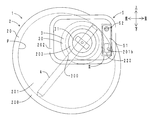
- FIG. 1 is a perspective view of the vane pump according to the first embodiment.
- FIG. 2 is a permeation right side view of the vane pump.
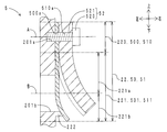
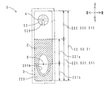
- FIG. 3 is an enlarged view in the frame III of FIG. 4 is a cross-sectional view in the IV-IV direction of FIG.
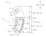
- FIG. 5 is a transparent right side view of the reed valve of the second embodiment.
- FIG. 6 is a transparent right side view of the reed valve of the third embodiment.
- FIG. 7 is a transparent right side view of the reed valve of the fourth embodiment.
- FIG. 8 is a transparent right side view of the reed valve of the fifth embodiment.
- FIG. 9 is a transparent right side view of the reed valve of the sixth embodiment.
- FIG. 1 the perspective view of the vane pump of this embodiment is shown.
- FIG. 2 shows a permeation right side view of the vane pump.
- the vane pump 1 includes a rotor 3, a vane 4, and a reed valve (check valve) 5.
- the reed valve 5 includes a housing 2, a valve (valve reed valve) 50 described later, a stopper (stopper reed valve) 51, and a fastening member 52.
- the housing 2 is fixed to a side surface of the engine (not shown).
- the housing 2 includes a housing body 20, an end plate 21, and a pump chamber P.
- the housing body 20 has a bottomed elliptical cylindrical shape.
- the housing body 20 includes a peripheral wall part 200, a bottom wall part 201, an outer cylinder part 202, and an inner cylinder part 203.
- the peripheral wall 200 has an elliptical cylindrical shape.
- the bottom wall 201 is disposed at the right end (one axial end) of the peripheral wall 200.
- the bottom wall portion 201 includes a fixing hole 201a and a discharge hole 201b.
- the discharge hole 201b penetrates the bottom wall portion 201 in the left-right direction.
- the discharge hole 201b can be opened and closed from the right side (outside) by a reed valve 5 described later.
- the outer cylinder part 202 has a rectangular frame shape.
- the outer cylinder portion 202 is disposed on the right surface (outer surface) of the bottom wall portion 201.
- the outer cylinder portion 202 is attached to a window portion of an engine cam carrier (not shown).
- the inner cylinder portion 203 has a circular frame shape.
- the inner cylinder part 203 is accommodated inside the outer cylinder part 202.
- a discharge hole 201b and a fixing hole 201a are arranged inside the frame of the outer
- the pump chamber P is partitioned inside the housing 2.
- the pump chamber P has an elliptical shape when viewed from the left or right side.
- a booster device (not shown) of a brake device communicates with the pump chamber P via an intake passage (not shown).
- the pump chamber P communicates with the outside of the pump chamber P through the discharge hole 201b.
- the discharge hole 201b is arranged at the end of the pump chamber P in the forward rotation direction (counterclockwise direction in FIG. 2).
- the rotor 3 includes a rotor main body 30 and a shaft portion 31.
- the rotor body 30 has a bottomed cylindrical shape that opens to the left.
- the rotor body 30 includes a pair of rotor groove portions 300.
- the shaft portion 31 continues to the right side of the rotor body 30.
- the shaft portion 31 is accommodated in the inner cylinder portion 203.
- the shaft portion 31 is connected to an engine camshaft (not shown) through a coupling (not shown) and an oil supply joint (not shown).
- the shaft portion 31, that is, the rotor 3 is rotatable around its own axis.
- the vane 4 has a rectangular plate shape.
- the vane 4 is accommodated in the pump chamber P.
- the vane 4 can rotate together with the rotor 3.
- the vane 4 can reciprocate in the diametrical direction along the pair of rotor grooves 300.
- the vane 4 can divide the pump chamber P into a plurality of working chambers according to the rotation angle.
- valve mounting portion 22 As shown in FIG. 1, a rectangular valve mounting portion 22 is defined in the bottom wall portion 201.
- the valve mounting portion 22 is disposed inside the frame of the outer cylinder portion 202 and outside the frame of the inner cylinder portion 203.
- the reed valve 5 is disposed in the valve mounting portion 22.
- FIG. 3 shows an enlarged view in the frame III of FIG.
- FIG. 4 shows a cross-sectional view in the IV-IV direction of FIG. Note that the reed valve shown in FIG. 4 is in a closed state.
- the valve mounting portion 22 includes a fixing portion 220 and a seat portion 221.
- the fixing portion 220 has a fixing hole 201a.
- the sheet part 221 is connected to the lower side of the fixed part 220.
- the sheet portion 221 has a discharge hole 201b.
- the sheet portion 221 is divided into a base portion 221a and a tip portion 221b.
- the base portion 221a is a portion of the sheet portion 221 that is closer to the center of gravity A of the discharge hole 201b than the center of gravity B of the discharge hole 201b when viewed from the right side (outside).
- the front end portion 221b is a portion of the sheet portion 221 that is farther from the center of gravity A of the fixing hole 201a than the center of gravity B of the discharge hole 201b when viewed from the right side.
- a rib-shaped convex portion 222 is provided so as to protrude from the portion included in the tip portion 221b toward the right side.
- the convex portion 222 extends in a C-shape that opens upward (toward the base portion 221a) along the opening edge of the discharge hole 201b.
- the reed valve 5 includes the housing 2, the valve 50, the stopper 51, and the fastening member 52 described above.
- the valve 50 is made of metal and has a plate shape.
- the valve 50 is elastically deformable.
- the valve 50 includes a valve side fastened portion 500 and a free portion 501.
- a valve side insertion hole 500 a is formed in the valve side fastened portion 500.
- the valve side fastened portion 500 covers the fixed portion 220 from the right side.
- the free part 501 continues to the lower side of the valve side fastened part 500. In the valve closed state, the free part 501 covers the seat part 221 from the right side.
- the free part 501 can open and close the discharge hole 201b from the right side.
- the stopper 51 is made of metal and has a plate shape.
- the stopper 51 is thicker than the valve 50. That is, the stopper 51 has higher rigidity than the valve 50. For this reason, the stopper 51 is less elastically deformed than the valve 50.
- the stopper 51 includes a stopper side fastened portion 510 and a restricting portion 511.
- a stopper side insertion hole 510 a is formed in the stopper side fastened portion 510.
- the stopper side fastened portion 510 covers the valve side fastened portion 500 from the right side.
- the restricting portion 511 continues to the lower side of the stopper side fastened portion 510. In the valve-closed state shown in FIG. 4, the restricting portion 511 is separated from the right surface of the free portion 501.
- the restricting portion 511 restricts the valve opening amount (elastic deformation amount of the free portion 501) of the valve 50 in the valve open state (indicated by a dotted line in FIG. 4). That is, the free portion 501 can be elastically deformed between the right regulating portion 511 and the left seat portion 221.
- the fastening member 52 is a screw.
- the fastening member 52 includes a head portion 520 and a shaft portion 521.
- the head 520 applies a pressing force (axial force) to the stopper side fastened portion 510.
- the shaft portion 521 continues to the left side of the head 520.
- the shaft portion 521 passes through the stopper side insertion hole 510a and the valve side insertion hole 500a.
- the left end (through end) of the shaft portion 521 is screwed into the fixing hole 201a.
- the free portion 501 and the seat portion 221 overlap as viewed from the right side.
- the non-contact part D shown by is formed.
- the contact portion C is disposed on the base portion 221a and the tip portion 221b. In the contact part C, the free part 501 and the sheet part 221 are in contact with each other. As shown by the solid line hatching at a narrow pitch in FIG. 3, the contact portion C includes a convex portion 222. The contact portion C surrounds the opening edge on the right side of the discharge hole 201b in an endless annular shape. That is, the contact part C seals the discharge hole 201b all around.
- the non-contact part D is arranged only at the tip part 221b.
- the free part 501 and the sheet part 221 (tip part 221b) are not in contact. That is, the convex part 222 is arrange
- the area of the contact portion C is smaller at the tip portion 221b than at the base portion 221a by the amount of the convex portion 222 disposed.
- the valve 50 includes a free part 501.
- the valve mounting portion 22 of the housing 2 includes a seat portion 221.
- the contact part C and the non-contact part D are between the free part 501 and the seat part 221. Is set.
- a base portion 221a and a tip portion 221b are set in the sheet portion 221.
- an oil film made of lubricating oil is formed between the free portion 501 and the sheet portion 221 (near the opening edge on the right side of the discharge hole 201b).
- the larger the area of the contact part C (the contact area between the free part 501 and the sheet part 221), the greater the surface tension of the oil film interposed between the free part 501 and the sheet part 221. For this reason, the suction
- the tip portion 221b and the like are the base portion 221a and the like (the portion corresponding to the base portion 221a in the base portion 221a and the free portion 501). Rather than the center of gravity A, that is, away from the fastening member 52. For this reason, the tip 221b and the like have a larger lift amount when the valve is opened than the base 221a and the like. Accordingly, the free end portion 501 is less likely to be separated from the seat portion 221 in the distal end portion 221b and the like than in the base portion 221a and the like. In other words, the distal end portion 221b and the like are more likely to cause a separation delay than the base portion 221a and the like.
- the tip portion 221b has a smaller area of the contact portion C indicated by solid line hatching than the base portion 221a.
- tip part 221b etc. can be suppressed. That is, it is possible to intensively suppress the separation delay in a portion where the lift amount is large when the valve is opened. Therefore, the valve seat delay of the entire seat portion 221, that is, the reed valve 5 can be suppressed. Therefore, it can suppress that the internal pressure of the pump chamber P becomes excessive.
- the non-contact part D is arrange
- the contact portion C seals the discharge hole 201b all around. That is, the non-contact portion D does not communicate the discharge hole 201b with the outside. For this reason, the non-contact portion D is closed as compared with the case where the discharge hole 201b communicates with the outside (for example, when the groove 222 that communicates the inside and outside of the discharge hole 201b is provided in the convex portion 222). Sealability in the valve state can be ensured.
- the convex part 222 is extended along the opening edge of the discharge hole 201b. For this reason, by adjusting the area of the right surface (outer surface) of the convex part 222, the area of the contact part C in an opening edge can be adjusted easily.
- the front and rear edges of the convex portion 222 are located on the right side (outer side) from the upper side (the fixed end side of the valve 50) to the lower side (the free end side of the valve 50). It has a slope that protrudes while curving. For this reason, the sealing performance in a valve closing state is securable.
- FIG. 5 shows a transparent right side view of the reed valve of the present embodiment.
- part corresponding to FIG. 3 it shows with the same code
- the valve mounting portion 22, the valve 50, and the stopper 51 extend in an arc shape (C shape) when viewed from the right side (outside).
- the curvature centers E of the valve mounting portion 22, the valve 50, and the stopper 51 are the same.
- a portion that is closer to the center of gravity B than the center of curvature E is an inner peripheral portion 221c
- a portion that is farther than the center of gravity B is an outer peripheral portion 221d.
- a convex part 222 is arranged along the opening edge (outer peripheral edge) of the discharge hole 201b.
- the free portion 501 is in contact with the right surface (outer surface) of the convex portion 222. That is, the contact portion C is disposed on the right surface of the convex portion 222.
- a non-contact portion D is disposed on the radially outer side (outer peripheral side) of the convex portion 222.
- the reed valve and the vane pump according to the present embodiment and the reed valve and the vane pump according to the first embodiment have the same functions and effects with respect to the parts having the same configuration.
- the outer peripheral portion 221d and the like are the inner peripheral portion 221c and the like (the inner peripheral portion 221c and “the inner portion 221c of the free portion 501 are corresponding).
- the lift amount at the time of valve opening is larger than the portion “). Therefore, the outer peripheral portion 221d and the like are more likely to be separated from the inner peripheral portion 221c and the like.
- the tip portion 221b has a smaller area of the contact portion C indicated by the solid line hatching than the base portion 221a. Moreover, the area of the contact portion C indicated by the solid line hatching is smaller in the outer peripheral portion 221d than in the inner peripheral portion 221c. For this reason, the separation delay in the front-end
- FIG. 6 is a transparent right side view of the reed valve of the present embodiment.
- a notch 222 a that is recessed on the left side (inner side) is formed on the right surface (outer surface) of the convex portion 222.
- the non-contact part D is arrange
- the notch portion 222a opens to the outer peripheral edge (non-contact portion D) of the convex portion 222. For this reason, the separation delay in the convex part 222 can be suppressed.
- the notch 222a opens at the inner periphery of the convex portion 222 (the opening edge of the discharge hole 201b). For this reason, the separation delay in the convex part 222 can be suppressed.
- the shapes and the like of the contact portion C and the non-contact portion D are adjusted by adjusting the shape and the like (shape, area, position, number of arrangements, etc.) of the notch 222a. can do.
- FIG. 7 shows a transparent right side view of the reed valve of the present embodiment.
- part corresponding to FIG. 3 it shows with the same code
- the convex part 222 surrounds the opening edge of the discharge hole 201b all around.
- the contact portion C is disposed on the convex portion 222 of the sheet portion 221.
- the upper edge of the convex part 222 has a larger area (the contact area with the free part 501 when the valve is closed) than the lower edge of the convex part 222.
- the non-contact part D is arrange
- the reed valve and the vane pump according to the present embodiment and the reed valve and the vane pump according to the first embodiment have the same functions and effects with respect to the parts having the same configuration.
- the shape and the like of the contact portion C and the non-contact portion D can be adjusted by adjusting the shape and the like of the right surface (outer surface) of the convex portion 222.
- FIG. 8 shows a transparent right side view of the reed valve of the present embodiment.
- a concave portion 223 that is recessed on the left side (inner side) is provided in the distal end portion 221b.
- the concave portion 223 surrounds a portion included in the distal end portion 221b in the opening edge of the discharge hole 201b.
- the recess 223 does not communicate with the discharge hole 201b.
- the reed valve and the vane pump according to the present embodiment and the reed valve and the vane pump according to the first embodiment have the same functions and effects with respect to the parts having the same configuration.
- the shape and the like of the contact portion C and the non-contact portion D can be adjusted by adjusting the shape and the like of the recess 223.
- FIG. 9 shows a transparent right side view of the reed valve of the present embodiment.
- a concave portion 223 that is recessed on the left side (inner side) is provided in the distal end portion 221b.
- the concave portion 223 surrounds a portion included in the distal end portion 221b in the opening edge of the discharge hole 201b.
- the recess 223 communicates with the discharge hole 201b.
- the reed valve and the vane pump according to the present embodiment and the reed valve and the vane pump according to the first embodiment have the same functions and effects with respect to the parts having the same configuration.
- the shape and the like of the contact portion C and the non-contact portion D can be adjusted by adjusting the shape and the like of the recess 223.
- the shape of the convex part 222, the concave part 223, and the notch part 222a is not particularly limited.
- the convex part 222 may have a protruding shape (boss shape).
- the recess 223 may have a groove shape.
- the convex portion 222 and the concave portion 223 may be appropriately combined and disposed on the sheet portion 221.
- the convex part 222, the concave part 223, and the notch part 222a may be arranged in the free part 501.
- the type of the fastening member 52 is not particularly limited. A bolt, a clip, etc. may be sufficient.
- the reed valve 5 can be implemented independently of the vane pump 1. That is, a member other than the housing 2 of the vane pump 1 may be used as the seat member of the reed valve 5. For example, a housing or piping of a machine (pump, compressor, blower, etc.) that operates with a fluid may be used as the seat member.
Landscapes
- Engineering & Computer Science (AREA)
- General Engineering & Computer Science (AREA)
- Mechanical Engineering (AREA)
- Rotary Pumps (AREA)
- Details And Applications Of Rotary Liquid Pumps (AREA)
- Check Valves (AREA)
Abstract
リードバルブ(5)は、弾性変形可能な自由部(501)を有するバルブ(50)と、自由部(501)の変形を規制するストッパ(51)と、自由部(501)に封止されるシート部(221)を有するシート部材(2)と、シート部材(2)の固定孔(201a)にバルブ(50)とストッパ(51)を固定する締結部材(52)と、を備える。閉弁状態において、自由部(501)とシート部(221)とが接触している部分を接触部(C)、接触していない部分を非接触部(D)とする。シート部(221)のうち、重心(A)からの距離が重心(B)よりも近い部分を基部(221a)、重心(B)よりも遠い部分を先端部(221b)とする。接触部(C)は、弁孔(201b)を全周的に封止する。非接触部(D)は、少なくとも先端部(221b)に配置される。基部(221a)よりも先端部(221b)の方が、接触部(C)の面積が小さい。
Description
本発明は、流体の逆流を規制するリードバルブ、および当該リードバルブを備えるベーンポンプに関する。
ベーンポンプのハウジングには、リードバルブが取り付けられている(例えば、特許文献1参照)。ハウジングには、固定孔と排出孔とが開設されている。排出孔の開口縁には、弁座が配置されている。リードバルブのバルブは、ボルトを介して、固定孔に固定されている。バルブは、片持ち梁状に揺動可能である。
閉弁状態において、バルブは弁座に着座している。バルブは、排出孔を封止している。ここで、バルブと弁座との間には、油膜が介在している。このため、開弁時において、バルブが弁座から迅速に離れにくい。したがって、リードバルブに開弁遅れが発生してしまう。特に、バルブのうち、固定孔から近い部分よりも、固定孔から遠い部分の方が、バルブが弁座から離れにくい。そこで、本発明は、開弁遅れを抑制可能なリードバルブおよびベーンポンプを提供することを目的とする。
上記課題を解決するため、本発明のリードバルブは、バルブ側挿通孔を有するバルブ側被締結部と、前記バルブ側被締結部に連なり弾性変形可能な自由部と、を有するバルブと、前記バルブの外側に配置され、ストッパ側挿通孔を有するストッパ側被締結部と、前記ストッパ側被締結部に連なり前記自由部の弾性変形量を規制する規制部と、を有するストッパと、前記バルブの内側に配置され、固定孔を有する固定部と、前記固定部に連なり閉弁状態において前記自由部に封止される弁孔を有するシート部と、を有するシート部材と、前記ストッパ側挿通孔および前記バルブ側挿通孔に挿通され、前記固定孔に固定される締結部材と、を備えるリードバルブであって、前記閉弁状態において、前記自由部と前記シート部とが接触している部分を接触部、前記自由部と前記シート部とが接触していない部分を非接触部として、前記シート部のうち、前記固定孔の重心からの距離が前記弁孔の重心よりも近い部分を基部、前記弁孔の重心よりも遠い部分を先端部として、前記接触部は、前記基部および前記先端部に配置され、前記弁孔を全周的に封止し、前記非接触部は、少なくとも前記先端部に配置され、前記基部よりも前記先端部の方が、前記接触部の面積が小さいことを特徴とする。
また、本発明のベーンポンプは、上記リードバルブと、内部にポンプ室を区画するハウジングと、を備え、前記シート部材は前記ハウジングであり、前記弁孔は前記ポンプ室に連通する排出孔であることを特徴とする。
バルブは、自由部を備えている。シート部材は、シート部を備えている。閉弁状態(自由部がシート部に着座し弁孔を封止している状態)において、バルブとシート部材との間には、接触部と非接触部とが設定されている。また、シート部には、基部と先端部とが設定されている。
接触部の面積(自由部とシート部との接触面積)が大きいほど、自由部とシート部との間に介在する油膜の表面張力が大きくなる。このため、シート部に対する自由部の吸着力が大きくなる。したがって、自由部がシート部から離座しにくくなる。言い換えると、離座遅れが発生しやすくなる。この点、本発明のリードバルブおよびベーンポンプによると、基部よりも先端部の方が、接触部の面積が小さい。このため、自由部が先端部から離座しやすい。したがって、先端部における離座遅れを抑制することができる。よって、リードバルブの開弁遅れを抑制することができる。
また、非接触部は、基部および先端部のうち、少なくとも先端部に配置されている。このため、基部の接触部の面積に対して、先端部の接触部の面積を、簡単に小さくすることができる。
また、閉弁状態において、接触部は、弁孔を全周的に封止している。すなわち、非接触部は、弁孔と外部とを連通していない。このため、閉弁状態におけるシール性を確保することができる。
以下、本発明のリードバルブおよびベーンポンプの実施の形態について説明する。
<第一実施形態>
図1に、本実施形態のベーンポンプの斜視図を示す。図2に、同ベーンポンプの透過右面図を示す。
図1に、本実施形態のベーンポンプの斜視図を示す。図2に、同ベーンポンプの透過右面図を示す。
[ベーンポンプの構成]
まず、本実施形態のベーンポンプの構成について説明する。図1、図2に示すように、ベーンポンプ1は、ロータ3と、ベーン4と、リードバルブ(逆止弁)5と、を備えている。リードバルブ5は、ハウジング2と、後述するバルブ(バルブリードバルブ)50と、ストッパ(ストッパリードバルブ)51と、締結部材52と、を備えている。
まず、本実施形態のベーンポンプの構成について説明する。図1、図2に示すように、ベーンポンプ1は、ロータ3と、ベーン4と、リードバルブ(逆止弁)5と、を備えている。リードバルブ5は、ハウジング2と、後述するバルブ(バルブリードバルブ)50と、ストッパ(ストッパリードバルブ)51と、締結部材52と、を備えている。
(ハウジング2)
ハウジング2は、エンジン(図略)の側面に固定されている。ハウジング2は、ハウジング本体20と、端板21と、ポンプ室Pと、を備えている。ハウジング本体20は、有底楕円筒状を呈している。ハウジング本体20は、周壁部200と、底壁部201と、外筒部202と、内筒部203と、を備えている。
ハウジング2は、エンジン(図略)の側面に固定されている。ハウジング2は、ハウジング本体20と、端板21と、ポンプ室Pと、を備えている。ハウジング本体20は、有底楕円筒状を呈している。ハウジング本体20は、周壁部200と、底壁部201と、外筒部202と、内筒部203と、を備えている。
周壁部200は、楕円筒状を呈している。底壁部201は、周壁部200の右端(軸方向一端)に配置されている。底壁部201は、固定孔201aと、排出孔201bと、を備えている。排出孔201bは、底壁部201を左右方向に貫通している。排出孔201bは、後述するリードバルブ5により、右側(外側)から開閉可能である。外筒部202は、矩形枠状を呈している。外筒部202は、底壁部201の右面(外面)に配置されている。外筒部202は、エンジンのカムキャリア(図略)の窓部に取り付けられる。内筒部203は、円形枠状を呈している。内筒部203は、外筒部202の枠内側に収容されている。外筒部202の枠内側かつ内筒部203の枠外側には、排出孔201bと、固定孔201aと、が配置されている。
図2に透過して示すように、ポンプ室Pは、ハウジング2の内部に区画されている。左側または右側から見て、ポンプ室Pは楕円形状を呈している。ポンプ室Pには、吸気通路(図略)を介して、ブレーキ装置の倍力装置(図略)が連通している。ポンプ室Pは、排出孔201bを介して、ポンプ室Pの外部と連通している。なお、排出孔201bは、ポンプ室Pの正回転方向(図2における反時計回り方向)の端部に配置されている。
(ロータ3、ベーン4)
図2に透過して示すように、ロータ3は、ロータ本体30と、軸部31と、を備えている。ロータ本体30は、左側に開口する有底円筒状を呈している。ロータ本体30は、一対のロータ溝部300を備えている。軸部31は、ロータ本体30の右側に連なっている。軸部31は、内筒部203に収容されている。軸部31は、カップリング(図略)および給油ジョイント(図略)を介して、エンジンのカムシャフト(図略)に連結されている。軸部31すなわちロータ3は、自身の軸周りに回転可能である。
図2に透過して示すように、ロータ3は、ロータ本体30と、軸部31と、を備えている。ロータ本体30は、左側に開口する有底円筒状を呈している。ロータ本体30は、一対のロータ溝部300を備えている。軸部31は、ロータ本体30の右側に連なっている。軸部31は、内筒部203に収容されている。軸部31は、カップリング(図略)および給油ジョイント(図略)を介して、エンジンのカムシャフト(図略)に連結されている。軸部31すなわちロータ3は、自身の軸周りに回転可能である。
ベーン4は、矩形板状を呈している。ベーン4は、ポンプ室Pに収容されている。ベーン4は、ロータ3と共に回転可能である。ベーン4は、一対のロータ溝部300に沿って直径方向に往復動可能である。ベーン4は、回転角度に応じて、ポンプ室Pを複数の作動室に区画可能である。
(リードバルブ5)
図1に示すように、底壁部201には、矩形状のバルブ取付部22が区画されている。バルブ取付部22は、外筒部202の枠内側かつ内筒部203の枠外側に配置されている。リードバルブ5は、バルブ取付部22に配置されている。
図1に示すように、底壁部201には、矩形状のバルブ取付部22が区画されている。バルブ取付部22は、外筒部202の枠内側かつ内筒部203の枠外側に配置されている。リードバルブ5は、バルブ取付部22に配置されている。
図3に、図2の枠III内の拡大図を示す。図4に、図3のIV-IV方向断面図を示す。なお、図4に示すリードバルブは閉弁状態である。図1、図3、図4に示すように、バルブ取付部22は、固定部220と、シート部221と、を備えている。固定部220には、固定孔201aが穿設されている。
シート部221は、固定部220の下側に連なっている。シート部221には、排出孔201bが穿設されている。図3に示すように、シート部221は、基部221aと、先端部221bと、に区画されている。基部221aは、シート部221のうち、右側(外側)から見て、固定孔201aの重心Aからの距離が排出孔201bの重心Bよりも近い部分である。先端部221bは、シート部221のうち、右側から見て、固定孔201aの重心Aからの距離が排出孔201bの重心Bよりも遠い部分である。排出孔201bの開口縁のうち、先端部221bに含まれる部分からは、右側に向かって、リブ状の凸部222が凸設されている。凸部222は、排出孔201bの開口縁に沿って、上側(基部221a側)に開口するC字状に延在している。
図1~図4に示すように、リードバルブ5は、前述のハウジング2と、バルブ50と、ストッパ51と、締結部材52と、を備えている。バルブ50は、金属製であって板状を呈している。バルブ50は、弾性変形可能である。バルブ50は、バルブ側被締結部500と、自由部501と、を備えている。バルブ側被締結部500には、バルブ側挿通孔500aが穿設されている。バルブ側被締結部500は、固定部220を、右側から覆っている。自由部501は、バルブ側被締結部500の下側に連なっている。閉弁状態において、自由部501は、シート部221を、右側から覆っている。自由部501は、排出孔201bを、右側から開閉可能である。
ストッパ51は、金属製であって板状を呈している。ストッパ51は、バルブ50よりも板厚が大きい。つまり、ストッパ51は、バルブ50よりも剛性が高い。このため、ストッパ51は、バルブ50よりも、弾性変形しにくい。ストッパ51は、ストッパ側被締結部510と、規制部511と、を備えている。ストッパ側被締結部510には、ストッパ側挿通孔510aが穿設されている。ストッパ側被締結部510は、バルブ側被締結部500を、右側から覆っている。規制部511は、ストッパ側被締結部510の下側に連なっている。図4に示す閉弁状態において、規制部511は、自由部501の右面から離間している。規制部511は、開弁状態(図4に点線で示す)におけるバルブ50の開弁量(自由部501の弾性変形量)を規制している。すなわち、自由部501は、右側の規制部511と左側のシート部221との間で、弾性変形可能である。
締結部材52は、スクリューである。締結部材52は、頭部520と、軸部521と、を備えている。頭部520は、ストッパ側被締結部510に、押圧力(軸力)を加えている。軸部521は、頭部520の左側に連なっている。軸部521は、ストッパ側挿通孔510a、バルブ側挿通孔500aを貫通している。軸部521の左端(貫通端)は、固定孔201aに螺着されている。
図3に示すように、閉弁状態においては、右側から見て、自由部501とシート部221とが重複している。自由部501とシート部221との間には、図3に実線ハッチング(前下-後上方向のハッチング)で示す接触部Cと、図3に点線ハッチング(前上-後下方向のハッチング)で示す非接触部Dと、が形成されている。
接触部Cは、基部221aおよび先端部221bに配置されている。接触部Cにおいては、自由部501とシート部221とが接触している。図3に挟ピッチの実線ハッチングで示すように、接触部Cは、凸部222を含んでいる。接触部Cは、排出孔201bの右側の開口縁を、無端環状に包囲している。すなわち、接触部Cは、排出孔201bを全周的に封止している。
非接触部Dは、先端部221bだけに配置されている。非接触部Dにおいては、自由部501とシート部221(先端部221b)とが接触していない。すなわち、先端部221bには、凸部222が配置されている。このため、閉弁状態において、自由部501は、凸部222だけに接触している。このように、凸部222が配置されている分だけ、基部221aよりも先端部221bの方が、接触部Cの面積が小さい。
[ベーンポンプの動き]
次に、本実施形態のベーンポンプの動きについて説明する。ベーン4は、図2における反時計回り方向に回転する。ポンプ室Pには、所定の油路(例えば、上流側から下流側に向かって、カムシャフト、給油ジョイント、カップリング、ロータを経由する油路)を介して、潤滑油が供給される。ベーン4の回転に伴って、ポンプ室Pに区画された複数の作動室の容積は、拡縮変化する。空気や潤滑油は、排出孔201bを介して、作動室から外部に排出される。バルブ50の自由部501には、左側(内側)から圧縮された作動室の圧力が、右側(外側)から外部の圧力が、加わる。
次に、本実施形態のベーンポンプの動きについて説明する。ベーン4は、図2における反時計回り方向に回転する。ポンプ室Pには、所定の油路(例えば、上流側から下流側に向かって、カムシャフト、給油ジョイント、カップリング、ロータを経由する油路)を介して、潤滑油が供給される。ベーン4の回転に伴って、ポンプ室Pに区画された複数の作動室の容積は、拡縮変化する。空気や潤滑油は、排出孔201bを介して、作動室から外部に排出される。バルブ50の自由部501には、左側(内側)から圧縮された作動室の圧力が、右側(外側)から外部の圧力が、加わる。
作動室の圧力が、外部からの圧力および自由部501の弾性力を上回ると、図4に実線で示す閉弁状態から、図4に点線で示す開弁状態に、自由部501が切り替わる。そして、排出孔201bを介して、作動室から外部に空気や潤滑油が排出される。排出により、作動室の圧力が、外部からの圧力および自由部501の弾性力を下回ると、開弁状態から閉弁状態に、再び自由部501が切り替わる。
[作用効果]
次に、本実施形態のリードバルブおよびベーンポンプの作用効果について説明する。図3に示すように、バルブ50は、自由部501を備えている。ハウジング2のバルブ取付部22は、シート部221を備えている。閉弁状態(自由部501がシート部221に着座し排出孔201bを封止している状態)において、自由部501とシート部221との間には、接触部Cと非接触部Dとが設定されている。また、シート部221には、基部221aと先端部221bとが設定されている。また、自由部501とシート部221との間(排出孔201bの右側の開口縁付近)には、潤滑油による油膜が形成されている。
次に、本実施形態のリードバルブおよびベーンポンプの作用効果について説明する。図3に示すように、バルブ50は、自由部501を備えている。ハウジング2のバルブ取付部22は、シート部221を備えている。閉弁状態(自由部501がシート部221に着座し排出孔201bを封止している状態)において、自由部501とシート部221との間には、接触部Cと非接触部Dとが設定されている。また、シート部221には、基部221aと先端部221bとが設定されている。また、自由部501とシート部221との間(排出孔201bの右側の開口縁付近)には、潤滑油による油膜が形成されている。
接触部Cの面積(自由部501とシート部221との接触面積)が大きいほど、自由部501とシート部221との間に介在する油膜の表面張力が大きくなる。このため、シート部221に対する自由部501の吸着力が大きくなる。したがって、接触部Cの面積が大きいほど、開弁時(図4に実線で示す閉弁状態から、図4に点線で示す開弁状態に、自由部501が切り替わる時)において、自由部501がシート部221から離座しにくくなる。
ここで、先端部221b等(先端部221bおよび「自由部501のうち先端部221bに対応する部分」)は、基部221a等(基部221aおよび「自由部501のうち基部221aに対応する部分」)よりも、重心Aつまり締結部材52から離間している。このため、先端部221b等は、基部221a等よりも、開弁時におけるリフト量が大きい。したがって、先端部221b等は、基部221a等よりも、自由部501がシート部221から離座しにくい。言い換えると、先端部221b等は、基部221a等よりも、離座遅れが発生しやすい。
この点、本実施形態のリードバルブ5およびベーンポンプ1によると、図3に示すように、基部221aよりも先端部221bの方が、実線ハッチングで示す接触部Cの面積が小さい。このため、先端部221b等における離座遅れを抑制することができる。すなわち、開弁時におけるリフト量が大きい部分の離座遅れを、重点的に抑制することができる。よって、シート部221全体つまりリードバルブ5の開弁遅れを抑制することができる。したがって、ポンプ室Pの内圧が過大になるのを、抑制することができる。また、基部221aに対する先端部221bの離座遅れを抑制することができる。
また、図3に示すように、非接触部Dは、基部221aおよび先端部221bのうち、先端部221bだけに配置されている。このため、基部221aの接触部Cの面積に対して、先端部221bの接触部Cの面積を、簡単に小さくすることができる。
また、図3に示すように、閉弁状態において、接触部Cは、排出孔201bを全周的に封止している。すなわち、非接触部Dは、排出孔201bと外部とを連通していない。このため、非接触部Dが排出孔201bと外部とを連通している場合(例えば、凸部222に排出孔201bの内外を連通する溝が凹設されている場合)と比較して、閉弁状態におけるシール性を確保することができる。
また、図3に示すように、凸部222は、排出孔201bの開口縁に沿って延在している。このため、凸部222の右面(外面)の面積を調整することにより、簡単に、開口縁における接触部Cの面積を調整することができる。また、図1、図4に示すように、凸部222の前後両縁は、上側(バルブ50の固定端側)から下側(バルブ50の自由端側)に向かって、右側(外側)に湾曲しながら突出するスロープ状を呈している。このため、閉弁状態におけるシール性を確保することができる。
<第二実施形態>
本実施形態のリードバルブおよびベーンポンプと、第一実施形態のリードバルブおよびベーンポンプとの相違点は、バルブおよびストッパが弧状に延在している点である。ここでは、相違点についてのみ説明する。図5に、本実施形態のリードバルブの透過右面図を示す。なお、図3と対応する部位については、同じ符号で示す。
本実施形態のリードバルブおよびベーンポンプと、第一実施形態のリードバルブおよびベーンポンプとの相違点は、バルブおよびストッパが弧状に延在している点である。ここでは、相違点についてのみ説明する。図5に、本実施形態のリードバルブの透過右面図を示す。なお、図3と対応する部位については、同じ符号で示す。
図5に示すように、右側(外側)から見て、バルブ取付部22、バルブ50、ストッパ51は、弧状(C字状)に延在している。バルブ取付部22、バルブ50、ストッパ51の曲率中心Eは、一致している。シート部221のうち、曲率中心Eからの距離が重心Bよりも近い部分を内周部221c、重心Bよりも遠い部分を外周部221dとする。外周部221dには、排出孔201bの開口縁(外周縁)に沿って、凸部222が配置されている。閉弁状態において、自由部501は、凸部222の右面(外面)に接触している。すなわち、凸部222の右面には、接触部Cが配置されている。凸部222の径方向外側(外周側)には、非接触部Dが配置されている。
本実施形態のリードバルブおよびベーンポンプと、第一実施形態のリードバルブおよびベーンポンプとは、構成が共通する部分に関しては、同様の作用効果を有する。外周部221d等(外周部221dおよび「自由部501のうち外周部221dに対応する部分」)は、内周部221c等(内周部221cおよび「自由部501のうち内周部221cに対応する部分」)よりも、開弁時におけるリフト量が大きい。したがって、外周部221d等は、内周部221c等よりも、離座遅れが発生しやすい。
この点、本実施形態のリードバルブ5およびベーンポンプによると、基部221aよりも先端部221bの方が、実線ハッチングで示す接触部Cの面積が小さい。並びに、内周部221cよりも外周部221dの方が、実線ハッチングで示す接触部Cの面積が小さい。このため、先端部221b等かつ外周部221d等における離座遅れを抑制することができる。すなわち、開弁時におけるリフト量が大きい部分の離座遅れを、重点的に抑制することができる。よって、シート部221全体つまりリードバルブ5の開弁遅れを抑制することができる。したがって、ポンプ室Pの内圧が過大になるのを、抑制することができる。また、基部221aおよび内周部221cに対する先端部221bおよび外周部221dの離座遅れを抑制することができる。
<第三実施形態>
本実施形態のリードバルブおよびベーンポンプと、第一実施形態のリードバルブおよびベーンポンプとの相違点は、凸部に切欠部が凹設されている点である。ここでは、相違点についてのみ説明する。図6に、本実施形態のリードバルブの透過右面図を示す。なお、図3と対応する部位については、同じ符号で示す。図6に示すように、凸部222の右面(外面)には、左側(内側)に凹む切欠部222aが凹設されている。切欠部222aには、非接触部Dが配置されている。
本実施形態のリードバルブおよびベーンポンプと、第一実施形態のリードバルブおよびベーンポンプとの相違点は、凸部に切欠部が凹設されている点である。ここでは、相違点についてのみ説明する。図6に、本実施形態のリードバルブの透過右面図を示す。なお、図3と対応する部位については、同じ符号で示す。図6に示すように、凸部222の右面(外面)には、左側(内側)に凹む切欠部222aが凹設されている。切欠部222aには、非接触部Dが配置されている。
本実施形態のリードバルブおよびベーンポンプと、第一実施形態のリードバルブおよびベーンポンプとは、構成が共通する部分に関しては、同様の作用効果を有する。本実施形態のリードバルブ5およびベーンポンプによると、切欠部222aは、凸部222の外周縁(非接触部D)に開口している。このため、凸部222における離座遅れを抑制することができる。並びに、切欠部222aは、凸部222の内周縁(排出孔201bの開口縁)に開口している。このため、凸部222における離座遅れを抑制することができる。また、本実施形態のリードバルブ5およびベーンポンプによると、切欠部222aの形状等(形状、面積、位置、配置数等)を調整することにより、接触部Cおよび非接触部Dの形状等を調整することができる。
<第四実施形態>
本実施形態のリードバルブおよびベーンポンプと、第一実施形態のリードバルブおよびベーンポンプとの相違点は、排出孔の開口縁を無端環状に凸部が包囲している点である。ここでは、相違点についてのみ説明する。図7に、本実施形態のリードバルブの透過右面図を示す。なお、図3と対応する部位については、同じ符号で示す。図7に示すように、凸部222は、排出孔201bの開口縁を、全周的に包囲している。シート部221のうち、凸部222には、接触部Cが配置されている。凸部222の上縁は、凸部222の下縁よりも、面積(閉弁時における自由部501との接触面積)が大きい。なお、シート部221のうち、凸部222以外の部分には、非接触部Dが配置されている。
本実施形態のリードバルブおよびベーンポンプと、第一実施形態のリードバルブおよびベーンポンプとの相違点は、排出孔の開口縁を無端環状に凸部が包囲している点である。ここでは、相違点についてのみ説明する。図7に、本実施形態のリードバルブの透過右面図を示す。なお、図3と対応する部位については、同じ符号で示す。図7に示すように、凸部222は、排出孔201bの開口縁を、全周的に包囲している。シート部221のうち、凸部222には、接触部Cが配置されている。凸部222の上縁は、凸部222の下縁よりも、面積(閉弁時における自由部501との接触面積)が大きい。なお、シート部221のうち、凸部222以外の部分には、非接触部Dが配置されている。
本実施形態のリードバルブおよびベーンポンプと、第一実施形態のリードバルブおよびベーンポンプとは、構成が共通する部分に関しては、同様の作用効果を有する。本実施形態のリードバルブ5およびベーンポンプによると、凸部222の右面(外面)の形状等を調整することにより、接触部Cおよび非接触部Dの形状等を調整することができる。
<第五実施形態>
本実施形態のリードバルブおよびベーンポンプと、第一実施形態のリードバルブおよびベーンポンプとの相違点は、凸部の代わりに凹部が配置されている点である。ここでは、相違点についてのみ説明する。図8に、本実施形態のリードバルブの透過右面図を示す。なお、図3と対応する部位については、同じ符号で示す。図8に示すように、先端部221bには、左側(内側)に凹む凹部223が凹設されている。凹部223は、排出孔201bの開口縁のうち、先端部221bに含まれる部分を包囲している。凹部223は、排出孔201bに連通していない。凹部223は、外部に連通している。
本実施形態のリードバルブおよびベーンポンプと、第一実施形態のリードバルブおよびベーンポンプとの相違点は、凸部の代わりに凹部が配置されている点である。ここでは、相違点についてのみ説明する。図8に、本実施形態のリードバルブの透過右面図を示す。なお、図3と対応する部位については、同じ符号で示す。図8に示すように、先端部221bには、左側(内側)に凹む凹部223が凹設されている。凹部223は、排出孔201bの開口縁のうち、先端部221bに含まれる部分を包囲している。凹部223は、排出孔201bに連通していない。凹部223は、外部に連通している。
本実施形態のリードバルブおよびベーンポンプと、第一実施形態のリードバルブおよびベーンポンプとは、構成が共通する部分に関しては、同様の作用効果を有する。本実施形態のリードバルブ5およびベーンポンプによると、凹部223の形状等を調整することにより、接触部Cおよび非接触部Dの形状等を調整することができる。
<第六実施形態>
本実施形態のリードバルブおよびベーンポンプと、第一実施形態のリードバルブおよびベーンポンプとの相違点は、凸部の代わりに凹部が配置されている点である。ここでは、相違点についてのみ説明する。図9に、本実施形態のリードバルブの透過右面図を示す。なお、図3と対応する部位については、同じ符号で示す。図9に示すように、先端部221bには、左側(内側)に凹む凹部223が凹設されている。凹部223は、排出孔201bの開口縁のうち、先端部221bに含まれる部分を包囲している。凹部223は、排出孔201bに連通している。凹部223は、外部に連通していない。
本実施形態のリードバルブおよびベーンポンプと、第一実施形態のリードバルブおよびベーンポンプとの相違点は、凸部の代わりに凹部が配置されている点である。ここでは、相違点についてのみ説明する。図9に、本実施形態のリードバルブの透過右面図を示す。なお、図3と対応する部位については、同じ符号で示す。図9に示すように、先端部221bには、左側(内側)に凹む凹部223が凹設されている。凹部223は、排出孔201bの開口縁のうち、先端部221bに含まれる部分を包囲している。凹部223は、排出孔201bに連通している。凹部223は、外部に連通していない。
本実施形態のリードバルブおよびベーンポンプと、第一実施形態のリードバルブおよびベーンポンプとは、構成が共通する部分に関しては、同様の作用効果を有する。本実施形態のリードバルブ5およびベーンポンプによると、凹部223の形状等を調整することにより、接触部Cおよび非接触部Dの形状等を調整することができる。
<その他>
以上、本発明のリードバルブおよびベーンポンプの実施の形態について説明した。しかしながら、実施の形態は上記形態に特に限定されるものではない。当業者が行いうる種々の変形的形態、改良的形態で実施することも可能である。
以上、本発明のリードバルブおよびベーンポンプの実施の形態について説明した。しかしながら、実施の形態は上記形態に特に限定されるものではない。当業者が行いうる種々の変形的形態、改良的形態で実施することも可能である。
凸部222、凹部223、切欠部222aの形状等は特に限定しない。凸部222は、突起状(ボス状)であってもよい。凹部223は、溝状であってもよい。また、凸部222と凹部223とを適宜組み合わせてシート部221に配置してもよい。また、凸部222、凹部223、切欠部222aを、自由部501に配置してもよい。
締結部材52の種類は特に限定しない。ボルト、クリップなどであってもよい。リードバルブ5は、ベーンポンプ1から独立して実施可能である。すなわち、リードバルブ5のシート部材として、ベーンポンプ1のハウジング2以外の部材を用いてもよい。例えば、流体により作動する機械(ポンプ、コンプレッサ、ブロワなど)のハウジングや配管などを、シート部材として用いてもよい。
1:ベーンポンプ、2:ハウジング、3:ロータ、4:ベーン、5:リードバルブ、20:ハウジング本体、21:端板、22:バルブ取付部、30:ロータ本体、31:軸部、50:バルブ、51:ストッパ、52:締結部材、200:周壁部、201:底壁部、201a:固定孔、201b:排出孔、202:外筒部、203:内筒部、220:固定部、221:シート部、221a:基部、221b:先端部、221c:内周部、221d:外周部、222:凸部、222a:切欠部、223:凹部、300:ロータ溝部、500:バルブ側被締結部、500a:バルブ側挿通孔、501:自由部、510:ストッパ側被締結部、510a:ストッパ側挿通孔、511:規制部、520:頭部、521:軸部、A:重心、B:重心、C:接触部、D:非接触部、E:曲率中心、P:ポンプ室
Claims (4)
- バルブ側挿通孔を有するバルブ側被締結部と、前記バルブ側被締結部に連なり弾性変形可能な自由部と、を有するバルブと、
前記バルブの外側に配置され、ストッパ側挿通孔を有するストッパ側被締結部と、前記ストッパ側被締結部に連なり前記自由部の弾性変形量を規制する規制部と、を有するストッパと、
前記バルブの内側に配置され、固定孔を有する固定部と、前記固定部に連なり閉弁状態において前記自由部に封止される弁孔を有するシート部と、を有するシート部材と、
前記ストッパ側挿通孔および前記バルブ側挿通孔に挿通され、前記固定孔に固定される締結部材と、
を備えるリードバルブであって、
前記閉弁状態において、前記自由部と前記シート部とが接触している部分を接触部、前記自由部と前記シート部とが接触していない部分を非接触部として、
前記シート部のうち、前記固定孔の重心からの距離が前記弁孔の重心よりも近い部分を基部、前記弁孔の重心よりも遠い部分を先端部として、
前記接触部は、前記基部および前記先端部に配置され、前記弁孔を全周的に封止し、
前記非接触部は、少なくとも前記先端部に配置され、
前記基部よりも前記先端部の方が、前記接触部の面積が小さいことを特徴とするリードバルブ。 - 前記シート部は、少なくとも前記先端部に配置される凹凸部を有し、
凹凸部は、凹部および凸部のうち少なくとも一方を有し、
前記凹部は、前記非接触部の少なくとも一部を区画し、
前記凸部は、前記接触部の少なくとも一部を区画する請求項1に記載のリードバルブ。 - 前記外側から見て、前記バルブは弧状を呈しており、
前記凹凸部は、前記弁孔の開口縁の外周部に配置される請求項2に記載のリードバルブ。 - 請求項1ないし請求項3のいずれかに記載のリードバルブと、内部にポンプ室を区画するハウジングと、を備え、前記シート部材は前記ハウジングであり、前記弁孔は前記ポンプ室に連通する排出孔であるベーンポンプ。
Applications Claiming Priority (2)
| Application Number | Priority Date | Filing Date | Title |
|---|---|---|---|
| JP2016-124567 | 2016-06-23 | ||
| JP2016124567A JP2017227282A (ja) | 2016-06-23 | 2016-06-23 | リードバルブおよびベーンポンプ |
Publications (1)
| Publication Number | Publication Date |
|---|---|
| WO2017221567A1 true WO2017221567A1 (ja) | 2017-12-28 |
Family
ID=60784619
Family Applications (1)
| Application Number | Title | Priority Date | Filing Date |
|---|---|---|---|
| PCT/JP2017/017587 Ceased WO2017221567A1 (ja) | 2016-06-23 | 2017-05-09 | リードバルブおよびベーンポンプ |
Country Status (2)
| Country | Link |
|---|---|
| JP (1) | JP2017227282A (ja) |
| WO (1) | WO2017221567A1 (ja) |
Citations (4)
| Publication number | Priority date | Publication date | Assignee | Title |
|---|---|---|---|---|
| JPS5396203U (ja) * | 1977-01-07 | 1978-08-04 | ||
| JPS55139206U (ja) * | 1979-03-26 | 1980-10-04 | ||
| JP2008169778A (ja) * | 2007-01-12 | 2008-07-24 | Calsonic Kansei Corp | 圧縮機 |
| JP2015102074A (ja) * | 2013-11-27 | 2015-06-04 | 大豊工業株式会社 | バキュームポンプ |
-
2016
- 2016-06-23 JP JP2016124567A patent/JP2017227282A/ja not_active Withdrawn
-
2017
- 2017-05-09 WO PCT/JP2017/017587 patent/WO2017221567A1/ja not_active Ceased
Patent Citations (4)
| Publication number | Priority date | Publication date | Assignee | Title |
|---|---|---|---|---|
| JPS5396203U (ja) * | 1977-01-07 | 1978-08-04 | ||
| JPS55139206U (ja) * | 1979-03-26 | 1980-10-04 | ||
| JP2008169778A (ja) * | 2007-01-12 | 2008-07-24 | Calsonic Kansei Corp | 圧縮機 |
| JP2015102074A (ja) * | 2013-11-27 | 2015-06-04 | 大豊工業株式会社 | バキュームポンプ |
Also Published As
| Publication number | Publication date |
|---|---|
| JP2017227282A (ja) | 2017-12-28 |
Similar Documents
| Publication | Publication Date | Title |
|---|---|---|
| CN105074214B (zh) | 具有多个压力腔室的可变容积泵 | |
| JP2022081500A (ja) | 流量可変バルブ機構および過給機 | |
| CN108343832A (zh) | 可变排量机油泵及其使用方法 | |
| CN109891098B (zh) | 叶片泵 | |
| WO2017221567A1 (ja) | リードバルブおよびベーンポンプ | |
| CN109072915B (zh) | 叶轮泵 | |
| JP2018025267A (ja) | リードバルブおよびベーンポンプ | |
| CN109923313B (zh) | 叶片泵 | |
| US20020051721A1 (en) | Vane pump | |
| JP2017227185A (ja) | リードバルブおよびベーンポンプ | |
| JP2004138159A (ja) | 油圧アクチュエータのシール構造 | |
| WO2018062479A1 (ja) | 圧縮機の弁構造 | |
| JP2001182511A (ja) | バルブタイミングコントロール装置用シール部材 | |
| JP2018031413A (ja) | リードバルブおよびベーンポンプ | |
| US11149730B2 (en) | Vane pump driven by an engine of an automobile | |
| JP2017227184A (ja) | リードバルブおよびベーンポンプ | |
| JP2017172471A (ja) | ベーンポンプ | |
| CN220749118U (zh) | 一种阀装置 | |
| JP2019218879A (ja) | 往復動式圧縮機の吸入弁構造及び往復動式圧縮機 | |
| KR20040027201A (ko) | 차량용 진공 펌프의 역류 방지 밸브 | |
| KR101737993B1 (ko) | 오일 펌프 | |
| JP2000009233A (ja) | 密封装置 | |
| JP2018031415A (ja) | リードバルブおよびベーンポンプ | |
| JP2018040254A (ja) | ポンプ | |
| KR101662553B1 (ko) | 베인펌프 |
Legal Events
| Date | Code | Title | Description |
|---|---|---|---|
| 121 | Ep: the epo has been informed by wipo that ep was designated in this application |
Ref document number: 17815037 Country of ref document: EP Kind code of ref document: A1 |
|
| NENP | Non-entry into the national phase |
Ref country code: DE |
|
| 122 | Ep: pct application non-entry in european phase |
Ref document number: 17815037 Country of ref document: EP Kind code of ref document: A1 |