WO2017217252A1 - 異物除去装置 - Google Patents
異物除去装置 Download PDFInfo
- Publication number
- WO2017217252A1 WO2017217252A1 PCT/JP2017/020553 JP2017020553W WO2017217252A1 WO 2017217252 A1 WO2017217252 A1 WO 2017217252A1 JP 2017020553 W JP2017020553 W JP 2017020553W WO 2017217252 A1 WO2017217252 A1 WO 2017217252A1
- Authority
- WO
- WIPO (PCT)
- Prior art keywords
- foreign matter
- carbon dioxide
- matter removing
- chamber
- removing apparatus
- Prior art date
- Legal status (The legal status is an assumption and is not a legal conclusion. Google has not performed a legal analysis and makes no representation as to the accuracy of the status listed.)
- Ceased
Links
Images



Classifications
-
- H—ELECTRICITY
- H10—SEMICONDUCTOR DEVICES; ELECTRIC SOLID-STATE DEVICES NOT OTHERWISE PROVIDED FOR
- H10P—GENERIC PROCESSES OR APPARATUS FOR THE MANUFACTURE OR TREATMENT OF DEVICES COVERED BY CLASS H10
- H10P72/00—Handling or holding of wafers, substrates or devices during manufacture or treatment thereof
- H10P72/04—Apparatus for manufacture or treatment
- H10P72/0402—Apparatus for fluid treatment
- H10P72/0406—Apparatus for fluid treatment for cleaning followed by drying, rinsing, stripping, blasting or the like
-
- B—PERFORMING OPERATIONS; TRANSPORTING
- B08—CLEANING
- B08B—CLEANING IN GENERAL; PREVENTION OF FOULING IN GENERAL
- B08B5/00—Cleaning by methods involving the use of air flow or gas flow
- B08B5/02—Cleaning by the force of jets, e.g. blowing-out cavities
-
- B—PERFORMING OPERATIONS; TRANSPORTING
- B08—CLEANING
- B08B—CLEANING IN GENERAL; PREVENTION OF FOULING IN GENERAL
- B08B7/00—Cleaning by methods not provided for in a single other subclass or a single group in this subclass
-
- H—ELECTRICITY
- H10—SEMICONDUCTOR DEVICES; ELECTRIC SOLID-STATE DEVICES NOT OTHERWISE PROVIDED FOR
- H10P—GENERIC PROCESSES OR APPARATUS FOR THE MANUFACTURE OR TREATMENT OF DEVICES COVERED BY CLASS H10
- H10P52/00—Grinding, lapping or polishing of wafers, substrates or parts of devices
-
- H—ELECTRICITY
- H10—SEMICONDUCTOR DEVICES; ELECTRIC SOLID-STATE DEVICES NOT OTHERWISE PROVIDED FOR
- H10P—GENERIC PROCESSES OR APPARATUS FOR THE MANUFACTURE OR TREATMENT OF DEVICES COVERED BY CLASS H10
- H10P72/00—Handling or holding of wafers, substrates or devices during manufacture or treatment thereof
- H10P72/04—Apparatus for manufacture or treatment
- H10P72/0431—Apparatus for thermal treatment
Definitions
- the present invention relates to a foreign matter removing device, and more particularly to a structure of a foreign matter removing device that removes foreign matter using solid carbon dioxide particles.
- a die bonding apparatus for bonding a semiconductor die cut from a wafer to a substrate, a wire bonding apparatus for connecting a semiconductor die electrode bonded to the substrate and a substrate electrode with a wire, and a semiconductor die
- Many devices such as a flip chip bonding apparatus are used in which bumps are formed on the electrodes and the semiconductor die is inverted and fixed to the substrate, and the electrodes of the semiconductor die and the substrate are connected.
- a bonding apparatus for laminating and bonding a semiconductor die on a semiconductor die of a wafer has also been used.
- a semiconductor die is bonded to a predetermined position of the substrate, or an electrode of the semiconductor die and an electrode of the substrate are connected by a wire.
- the adhesive strength of the adhesive may be reduced.
- dust or the like adheres to the surface of the substrate electrode or the semiconductor die electrode, the bonding quality between the electrode and the wire may deteriorate.
- liquid carbon dioxide CO 2
- a technique for removing foreign matter from a semiconductor die or a substrate using liquid carbon dioxide (CO 2 ) is also used (see, for example, Patent Document 2).
- liquid carbon dioxide is sprayed from a spray nozzle onto a substrate, and dry ice particles that have been frozen by adiabatic expansion during spraying to become dry ice collide with the substrate, so that foreign matter on the surface of a semiconductor die or substrate can be removed. The removal is performed.
- an object of the present invention is to remove minute foreign matters while suppressing damage to a substrate and a semiconductor die.
- the foreign matter removing apparatus of the present invention expands a pressurized flow of liquid carbon dioxide, and forms a solid carbon dioxide particle in the flow by cooling at the time of expansion, and is connected to the nozzle.
- the foreign matter removing apparatus is characterized in that the particle diameter of individual carbon dioxide particles ejected from the ejection port is adjusted by changing the interval between the nozzle and the chamber.
- the particle diameter of individual carbon dioxide particles ejected from the ejection port by changing the heating amount of the heater, including a heater attached to the outer surface of the chamber.
- the jet outlet is preferably a slit that communicates with the chamber and jets the carbon dioxide particles in a strip shape toward the surface of the flat plate member.
- the jet port is a plurality of holes arranged in a straight line in communication with the chamber.
- the ejection port injects the carbon dioxide particles while inclining the carbon dioxide particles in the direction of the suction port.
- the foreign matter removing apparatus of the present invention may further include an air inlet for allowing compressed air to flow into the chamber, and the chamber may be suitable for mixing the carbon dioxide particles and the compressed air.
- the present invention can remove minute foreign matters while suppressing damage to the substrate and the semiconductor die.
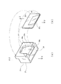
- FIG. 2 is an explanatory perspective view showing a structure of a main body and a lid of the cleaning head of the foreign matter removing apparatus shown in FIG. 1 and an assembly of the lid to the main body. It is the figure which looked at the lower surface in which the suction opening and slit of the cleaning head shown in FIG. 1 are arrange
- FIG. 7 is a diagram of a lower surface where a suction port and an ejection port of a cleaning head of a foreign matter removing apparatus according to another embodiment of the present invention are arranged as viewed from above, and shows the operation of the foreign matter removing apparatus according to another embodiment of the present invention. It is explanatory drawing shown.
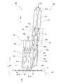
- the foreign matter removing apparatus 100 includes a cleaning head 20 and a drive unit 40 that moves the cleaning head 20 in a direction orthogonal to the transport direction.
- the transport direction of the substrate 13 which is a flat plate member guided by the guide rails 11 and 12 and transported in the horizontal direction is the X direction
- the direction perpendicular to the X direction on the same plane as the X direction is the Y direction.
- the direction perpendicular to the XY plane will be described as the Z direction.
- a stage 45 that vacuum-sucks and heats the substrate 13 is disposed below the substrate 13.
- the cleaning head 20 has a rectangular parallelepiped shape in which a lid 22 is attached to a rear surface 21 b of a main body 21, and solid carbon dioxide particles (hereinafter referred to as dry ice particles) for removing foreign substances are supplied to the upper part.
- An inlet connection pipe 25 and a suction connection pipe 26 connected to a vacuum device (not shown) are attached.
- one side surface of the cleaning head 20 is connected to an arm 28 via a connection member 27.
- the arm 28 reciprocates in the Y direction by the drive unit 40.
- the cleaning head 20 is attached to the arm 28 so as to be slightly inclined with respect to the surface of the substrate 13. There is a gap between the surface of the substrate 13 and the lower surface of the cleaning head 20, and the cleaning head 20 moves on the upper side of the substrate 13 in the Y direction along the surface of the substrate 13.
- the cleaning head 20 includes a main body 21 and a lid 22 that is fixed to the rear surface 21 b of the main body 21.
- a rectangular suction port 24 is dug in the lower surface of the main body 21. Further, the rear surface 21b of the main body 21 is formed with a recess 29a constituting a chamber 29 described later. The lower side of the recess 29 a is an inclined surface 29 b that is inclined toward the suction port 24.
- the lid 22 includes a flange 22 a that is in close contact with a flat surface other than the recess 29 a of the rear surface 21 b of the main body 21, and a wedge-shaped inclined portion 22 b that is parallel to the inclined surface 29 b of the main body 21. ing.
- the inclined portion 22b of the lid 22 is aligned with the inclined surface 29b of the main body and the flange 22a is screwed to the rear surface 21b as shown in FIG. 3B, the concave portion 29a of the main body 21 and the lid 22 are shown in FIG.
- a chamber 29 extending linearly in the X direction is formed between the first flange 22a and the second flange 22a.
- a slit which is an injection port that injects a mixed fluid of gaseous carbon dioxide and dry ice particles in a band shape toward the surface of the substrate 13 between the inclined surface 29 b of the main body 21 and the inclined portion 22 b of the lid 22. 23 is formed.
- the slit 23 is inclined toward the suction port 24.
- the length of the suction port 24 in the X direction is longer than the length of the slit 23 in the X direction, and extends to the vicinity of both side surfaces of the cleaning head 20 from the slit 23.
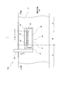
- FIG. 4 is a view of the lower surface of the cleaning head 20 where the suction port 24 and the slit 23 are disposed as viewed from above.
- a sleeve 30 is connected to the inlet connection pipe 25, and a nozzle 31 is connected to the sleeve 30.
- the sleeve 30 is provided with threaded portions 30a and 30b on the inlet side and the outlet side, respectively, the threaded portion 30a on the inlet side meshes with the threaded portion 31b on the outlet side of the nozzle, and the threaded portion 30b on the outlet side It meshes with the threaded portion 25 a on the inlet side of the inlet connecting pipe 25.
- the sleeve 30 adjusts the engagement length between the screw portion 30a on the inlet side and the screw portion 31b on the outlet side of the nozzle, and the engagement length between the screw portion 30b on the outlet side and the screw portion 25a on the inlet side of the inlet connection pipe 25. By doing so, the distance from the outlet of the nozzle 31 to the chamber 29 can be changed.
- the nozzle 31 is connected to a liquid carbon dioxide supply device that supplies pressurized liquid carbon dioxide. Further, as shown in FIG. 2, a heater 35 is attached to the back surface of the lid 22.
- the stage 45 vacuum-sucks and fixes the substrate 13 and turns on the built-in heater to turn the substrate 13 on, for example, 80 Heat to about °C.
- pressurized liquid carbon dioxide supplied to the nozzle 31 from a liquid carbon dioxide supply device (not shown) is introduced.
- the liquid carbon dioxide flowing into the nozzle 31 is compressed up to the throttle portion 31c of the nozzle 31, and when it passes through the throttle portion 31c, it adiabatically expands and the temperature decreases. Due to this temperature decrease, the liquid carbon dioxide changes to solid carbon dioxide particles (dry ice particles). Moreover, a part changes to gaseous carbon dioxide.
- the mixed fluid of gaseous carbon dioxide and dry ice particles flows from the nozzle 31 through the sleeve 30 and the inlet connection pipe 25 into the chamber 29 of the cleaning head 20 as indicated by an arrow 91 in FIG. .
- the mixed fluid of gaseous carbon dioxide and dry ice particles flowing into the chamber 29 is jetted obliquely downward toward the surface of the substrate 13 through the slit 23. Since the substrate 13 is heated to about 80 ° C. by the stage 45, when the dry ice particles collide with the minute foreign matter 50 on the surface of the substrate 13, the dry ice particles instantaneously sublimate and expand into gaseous carbon dioxide. Become. The minute foreign matter 50 adhering to the surface of the substrate 13 is removed from the surface of the substrate 13 by the fluid force during the sublimation and expansion. Since the mixed fluid of gaseous carbon dioxide and dry ice particles is ejected from the slit 23 in the direction of the suction port 24 as indicated by an arrow 95 in FIG.
- the minute foreign matter 50 removed from the surface of the substrate 13 is As shown by an arrow 92 in FIG. 2, the air is sucked into a suction port 24 provided adjacent to the slit 23 and sucked from a suction connection pipe 26 to a vacuum device (not shown).
- the minute foreign matter 50 is, for example, one having a size of less than 50 ⁇ m.
- gaseous carbon dioxide ejected from the slits 23 together with the dry ice particles is ejected obliquely downward from the slits 23 toward the surface of the substrate 13 and is attached to the surface of the substrate 13.
- the foreign matter 51 larger than 50 is blown off and removed.
- the foreign matter 51 blown off by gaseous carbon dioxide is also sucked into a suction port 24 provided adjacent to the slit 23 and sucked into a vacuum device (not shown) from the suction connection pipe 26.
- the fine foreign matter 50 and the foreign matter 51 in the region B of the substrate 13 shown in FIG. 4 is a region where the removal of the minute foreign matter 50 and the foreign matter 51 on the surface of the substrate 13 is completed, and the region C on the upstream side in the transport direction of the region B is: This is a region where the fine foreign matter 50 and the foreign matter 51 on the surface of the substrate 13 are not removed.
- the length of the suction port 24 in the Y direction is longer than the length of the slit 23 in the Y direction, and on both side surfaces of the cleaning head 20 than the slit 23. It extends to the vicinity. For this reason, the fine foreign matter 50 and the foreign matter 51 removed from the surface of the substrate 13 by the mixed fluid of gaseous carbon dioxide and dry ice particles ejected from the slit 23 are blown away in a direction inclined from the Y direction to the X direction. Even in this case, the blown-out minute foreign matter 50 and foreign matter 51 can be sucked by the suction port 24. For this reason, it can suppress that the fine foreign material 50 and the foreign material 51 adhere again to the surface of the board
- the particle size of the dry ice particles sprayed on the substrate 13 is too large, the fine foreign matter 50 cannot be effectively removed, and the substrate 13 is damaged by the collision of the dry ice particles.
- the particle diameter of the dry ice particles is set to the submicron order, the minute foreign matter 50 can be removed without damaging the substrate 13 or the semiconductor die attached to the substrate 13.
- the particle diameter of the dry ice particles ejected from the nozzle 31 becomes smaller as the flight distance L from the outlet of the nozzle 31 becomes longer as shown in FIG. Further, as shown in FIG. 6, the particle diameter of the dry ice particles ejected from the nozzle 31 decreases as the atmospheric temperature T during flight increases. Accordingly, the foreign matter removing apparatus 100 according to the present embodiment is configured so that the engagement length between the screw portion 30a on the inlet side of the sleeve 30 and the screw portion 31b on the outlet side of the nozzle, and the inlet side of the screw portion 30b on the outlet side and the inlet connection pipe 25 is set.
- the particle size of the dry ice particles ejected from the slit 23 can be adjusted by changing the flight distance L from the outlet of the nozzle 31 to the chamber 29. Further, the foreign matter removing apparatus 100 of the present embodiment adjusts the particle size of the dry ice particles ejected from the slit 23 by changing the temperature of the chamber 29 by the heater 35 attached to the back surface of the lid 22 constituting the chamber 29. be able to.
- the meshing lengths of the screw portions 30a and 30b of the sleeve 30 and the heating heat amount of the heater 35 may be adjusted by a test or the like so that the particle diameter of the dry ice particles ejected from the slit 23 is on the order of submicrons. Further, the particle size of the dry ice particles may be adjusted by using only one of the meshing length of the screw portions 30a and 30b of the sleeve 30 and the heating by the heater 35.
- the foreign matter removing apparatus 100 can adjust the particle size of the dry ice particles to the submicron order by the flight distance L from the outlet of the nozzle 31 to the chamber 29 and the heating of the chamber 29. Therefore, it is possible to effectively remove the minute foreign matter 50 of less than 50 ⁇ m attached to the surface of the substrate 13 or the semiconductor die without damaging the substrate 13 or the semiconductor die.
- the foreign matter removing apparatus 200 has an air inlet 25 c on the side surface of the sleeve 30.
- the foreign matter removing apparatus 200 allows compressed air to flow into the chamber 29 together with gaseous carbon dioxide and dry ice particles, and mixes gaseous carbon dioxide, dry ice particles, and compressed air in the chamber 29, and slits 23.
- the mixed fluid of compressed air, gaseous carbon dioxide, and dry ice particles is ejected from the substrate to remove the minute foreign matter 50 and the foreign matter 51 from the substrate 13.
- the foreign substance removal apparatus 200 of this embodiment can increase the flow rate of the fluid ejected from the slit 23 as compared with the foreign substance removal apparatus 100 described above, even when the foreign substance 51 larger than the fine foreign substance 50 adheres more. Thus, the minute foreign matter 50 and the foreign matter 51 can be effectively removed. It is also possible to adjust the particle diameter of the dry ice particles ejected from the slit 23 by adjusting the temperature of the air flowing in from the air inlet 25c.
- the air inlet 25 c that allows the compressed air to flow into the sleeve 30 is provided.
- the air inlet 25 c allows the compressed air to flow into the chamber 29 to form gaseous carbon dioxide.
- it is a position where dry ice particles and compressed air are mixed, they may be placed anywhere, for example, on the lid 22.
- the foreign matter removing apparatus 300 of the present embodiment has a hole 61 communicating with the chamber 29 arranged in a straight line instead of the slit 23 of the foreign matter removing apparatus 100 described with reference to FIGS. 1 to 6. This is a squirt outlet.
- the cleaning head 20 is reciprocated in the Y direction while jetting a mixed fluid of gaseous carbon dioxide and dry ice particles as shown by an arrow 96 in FIG.
- the minute foreign matter 50 and the foreign matter 51 in the region B of the substrate 13 shown in FIG. 8 are removed.
- the foreign matter removing apparatus 300 of the present embodiment has the same effects as the foreign matter removing apparatus 100 described with reference to FIGS. 1 to 6.
- the cleaning head 20 is described as being attached to the arm 28 so as to incline from the vertical direction toward the lid 22, but as shown in FIG. If the cleaning head 20 is configured to be inclined, the cleaning head 20 may be attached to the arm 28 in a vertically standing state.
- a mixed fluid of gaseous carbon dioxide and dry ice particles, or a mixed fluid of gaseous carbon dioxide, dry ice particles, and air is directed toward the substrate 13 that is a flat plate member.
- the foreign matter removing apparatus 100, 200, 300 of the present embodiment is, for example, a minute foreign matter 50, foreign matter attached to the surface of a semiconductor wafer, a lead frame in which a semiconductor die is bonded on a substrate, or the like. It can also be applied when removing 51.
- the foreign matter removing apparatuses 100, 200, and 300 of each embodiment can be incorporated into an electronic component mounting apparatus such as a die bonding apparatus, a wire bonding apparatus, and a flip chip bonding apparatus.
- the foreign matter removing apparatuses 100, 200, and 300 according to the present embodiment can be applied to removing foreign matters on the surface of a flat plate member such as glass or film.
Landscapes
- Cleaning Or Drying Semiconductors (AREA)
- Cleaning In General (AREA)
- Cleaning By Liquid Or Steam (AREA)
Abstract
液体の二酸化炭素の加圧流れを膨張させて、膨張の際の冷却により、その流れの中にドライアイス粒子を形成するノズル(31)と、ノズル(31)に接続されて固体の二酸化炭素粒子が流入するチャンバ(29)と、チャンバ(29)に接続されてドライアイス粒子を基板(13)の表面に向かって噴出させるスリット(23)と、スリット(23)に隣接して配置される吸引口(24)と、を備える異物除去装置(100)において、ノズル(31)とチャンバ(29)との間隔を変化させてスリット(23)から噴出するドライアイス粒子の粒子径を調整する。これにより、基板や半導体ダイの損傷を抑制しつつ微小な異物を除去する。
Description
本発明は、異物除去装置、特に、固体の二酸化炭素粒子により異物の除去を行う異物除去装置の構造に関する。
IC等の電子部品の製造工程では、ウェーハから切り出した半導体ダイを基板に接着するダイボンディング装置、基板に接合された半導体ダイの電極と基板の電極とをワイヤで接続するワイヤボンディング装置、半導体ダイの電極の上にバンプを形成しておき、半導体ダイを反転させて基板に固定すると共に半導体ダイの電極と基板の電極とを接続するフリップチップボンディング装置等の多くの装置が用いられている。また、最近では、ウェーハの半導体ダイの上に半導体ダイを積層接合するボンディング装置も用いられている。
このようなボンディング装置では、基板の所定の位置に半導体ダイをボンディングしたり、半導体ダイの電極と基板の電極とをワイヤで接続したりしている。
このような装置において、基板等の表面にゴミ等の異物が付着していると、接着剤の接着力が低下する場合がある。また、基板の電極や半導体ダイの電極の表面にゴミ等が付着していると、電極とワイヤとの接合品質が低下する場合がある。
このため、基板に対して空気を吹き付けて基板に付着している異物を吹き飛ばし、吹き飛んだ異物を吸引回収して異物の除去を行う装置が提案されている(例えば、特許文献1参照)。
また、液体の二酸化炭素(CO2)を用いて半導体ダイや基板の異物を除去する技術も利用されている(例えば、特許文献2参照)。この方法は、液体の二酸化炭素を噴射ノズルから基板に噴射させ、噴射時の断熱膨張により凍結してドライアイスとなったドライアイス粒子を基板に衝突させて、半導体ダイや基板の表面の異物の除去を行うものである。
しかし、特許文献2に記載された異物除去方法では、より微小な異物を除去するためにドライアイス粒子を勢いよく噴射すると、ドライアイス粒子の粒子径が大きくなってしまい、微小な異物を効果的に除去できなくなるという問題があった。また、ドライアイスの粒子径が大きくなると、ドライアイス粒子の衝突により基板や半導体ダイが損傷してしまうという問題があった。
そこで、本発明は、基板や半導体ダイの損傷を抑制しつつ微小な異物を除去することを目的とする。
本発明の異物除去装置は、液体の二酸化炭素の加圧流れを膨張させて、膨張の際の冷却により、その流れの中に固体の二酸化炭素粒子を形成するノズルと、ノズルに接続され、固体の二酸化炭素粒子が流入するチャンバと、チャンバに接続され、固体の二酸化炭素粒子を平板状部材の表面に向かって噴出させる噴出口と、噴出口に隣接して配置される吸引口と、を備える異物除去装置であって、ノズルとチャンバとの間隔を変化させて噴出口から噴出する個体の二酸化炭素粒子の粒子径を調整することを特徴とする。
本発明の異物除去装置において、チャンバの外面に取り付けられたヒータを含み、ヒータの加熱量を変化させて噴出口から噴出する個体の二酸化炭素粒子の粒子径を調整することとしても好適である。
本発明の異物除去装置において、前記噴出口は、前記チャンバに連通して前記二酸化炭素粒子を平板状部材の表面に向かって帯状に噴出するスリットであることとしても好適である。
本発明の異物除去装置において、前記噴出口は、前記チャンバに連通し、直線状に配置された複数の孔であることとしても好適である。
本発明の異物除去装置において、前記噴出口は、前記吸引口の方向に前記二酸化炭素粒子を傾斜させて噴射することとしても好適である。
本発明の異物除去装置において、前記チャンバに圧縮空気を流入させる空気注入口をさらに備え、前記チャンバは、前記二酸化炭素粒子と前記圧縮空気とを混合することとしても好適である。
本発明は、基板や半導体ダイの損傷を抑制しつつ微小な異物を除去することができる。
以下、図面を参照しながら本実施形態の異物除去装置100について説明する。図1に示すように、本実施形態の異物除去装置100は、クリーニングヘッド20と、クリーニングヘッド20を搬送方向と直交方向に移動させる駆動部40とを備えている。図1において、ガイドレール11、12によってガイドされて水平方向に搬送される平板状部材である基板13の搬送方向がX方向であり、X方向と同一面でX方向と直交する方向をY方向、XY面に垂直な方向をZ方向として説明する。また、基板13の下側には、基板13を真空吸着すると共に加熱するステージ45が配置されている。
図1に示すように、クリーニングヘッド20は、本体21の後面21bに蓋22が取り付けられた直方体形状で、上部に異物除去用の固体の二酸化炭素粒子(以下、ドライアイス粒子という)が供給される入口接続管25と、図示しない真空装置に接続される吸引接続管26とが取り付けられている。
図1に示すように、クリーニングヘッド20の一方の側面は、接続部材27を介してアーム28に接続されている。アーム28は、駆動部40によってY方向に往復移動する。クリーニングヘッド20は、基板13の表面に対して若干傾斜するように、アーム28に取り付けられている。基板13の表面とクリーニングヘッド20の下面との間には隙間が開いており、クリーニングヘッド20は基板13の上側を基板13の表面に沿ってY方向に移動する。
次に、図2、図3(a)、図3(b)を参照しながら、本実施形態の異物除去装置100のクリーニングヘッド20の構造について説明する。図2、図3(a)、図3(b)に示すように、クリーニングヘッド20は、本体21と、本体21の後面21bに固定される蓋22とによって構成される。
図3(a)に示すように、本体21の下面には、長方形の吸引口24が掘り込まれている。また、本体21の後面21bには、後で説明するチャンバ29を構成する凹部29aが形成されている。凹部29aの下側は、吸引口24に向かって傾斜する傾斜面29bとなっている。
図3(b)に示すように、蓋22は、本体21の後面21bの凹部29a以外の平面部に密着するフランジ22aと、本体21の傾斜面29bと平行な楔状の傾斜部22bとを備えている。図3(b)に示すように、蓋22の傾斜部22bを本体の傾斜面29bに合わせてフランジ22aを後面21bにねじ止めすると、図2に示すように、本体21の凹部29aと蓋22のフランジ22aとの間にX方向に直線状に延びるチャンバ29が形成される。そして、本体21の傾斜面29bと蓋22の傾斜部22bとの間には、基板13の表面に向かって帯状に気体の二酸化炭素とドライアイス粒子との混合流体を噴射する噴射口であるスリット23が形成される。図2に示すように、スリット23は、吸引口24の方向に向かって傾斜している。また、図4に示すように、吸引口24のX方向の長さは、スリット23のX方向の長さよりも長く、スリット23よりもクリーニングヘッド20の両側面の近傍まで延びている。なお、図4は、クリーニングヘッド20の吸引口24とスリット23とが配置されている下面を上方向から見た図である。
図2に示すように、入口接続管25には、スリーブ30が接続され、スリーブ30には、ノズル31が接続されている。スリーブ30は、入口側と出口側にそれぞれねじ部30a,30bが設けられており、入口側のねじ部30aはノズルの出口側のねじ部31bと噛み合っており、出口側のねじ部30bは、入口接続管25の入口側のねじ部25aと噛み合っている。スリーブ30は、入口側のねじ部30aとノズルの出口側のねじ部31bの噛み合い長さおよび、出口側のねじ部30bと入口接続管25の入口側のねじ部25aとの噛み合い長さを調整することにより、ノズル31の出口からチャンバ29までの距離を変化させることができる。ノズル31は加圧された液体の二酸化炭素を供給する液体二酸化炭素供給装置に接続されている。また、図2に示すように、蓋22の背面には、ヒータ35が取り付けられている。
以上のように構成された異物除去装置100の動作について、図2、図4~6を参照しながら説明する。図示しない搬送装置によって基板13がステージ45の上まで搬送されて来ると、ステージ45は、基板13を真空吸着して固定すると共に、内蔵されているヒータをオンにして基板13を、例えば、80℃程度まで加熱する。
次に、図示しない液体二酸化炭素供給装置からノズル31に供給された加圧された液体の二酸化炭素を流入させる。ノズル31に流入した液体の二酸化炭素は、ノズル31の絞り部31cまでは圧縮され、絞り部31cを通過すると断熱膨張し温度が低下する。この温度低下によって、液体の二酸化炭素が固体の二酸化炭素の粒子(ドライアイス粒子)に変化する。また、一部は、気体の二酸化炭素に変化する。この気体の二酸化炭素とドライアイス粒子との混合流体は、図2の矢印91に示すように、ノズル31からスリーブ30、入口接続管25の内部を通過してクリーニングヘッド20のチャンバ29に流入する。チャンバ29に流入した気体の二酸化炭素とドライアイス粒子との混合流体は、スリット23を通って基板13の表面に向かって斜め下向きに噴射される。基板13は、ステージ45によって80℃程度に加熱されているので、基板13の表面の微小異物50にドライアイス粒子が衝突すると、ドライアイス粒子は瞬間的に昇華、膨張して気体の二酸化炭素になる。基板13の表面に付着していた微小異物50は、この昇華、膨張の際の流体力によって基板13の表面から除去される。気体の二酸化炭素とドライアイス粒子との混合流体は、図4の矢印95のようにスリット23から吸引口24の方向に傾斜て噴射されるので、基板13の表面から除去された微小異物50は、図2の矢印92に示すように、スリット23に隣接して設けられている吸引口24の中に吸い込まれ、吸引接続管26から図示しない真空装置に吸引される。ここで、微小異物50とは、例えば、大きさが50μm未満のものをいう。
また、スリット23からドライアイス粒子とともに噴出した気体の二酸化炭素も、ドライアイス粒子と同様、スリット23から基板13の表面に向かって斜め下向きに噴射され、基板13の表面に付着している微小異物50よりも大きい異物51を吹き飛ばして除去する。気体の二酸化炭素によって吹き飛ばされた異物51も、スリット23に隣接して設けられている吸引口24の中に吸い込まれ、吸引接続管26から図示しない真空装置に吸引される。
そして、図4に示すように、気体の二酸化炭素とドライアイス粒子の混合流体をスリット23から図4の矢印95のように噴射させながらクリーニングヘッド20をY方向に往復動させると、クリーニングヘッド20が通過した図4に示す基板13の領域Bの微小異物50、異物51が除去される。なお、図4に示す領域Bの搬送方向下流側の領域Aは、基板13の表面の微小異物50、異物51の除去が終了した領域であり、領域Bの搬送方向上流側の領域Cは、基板13の表面の微小異物50、異物51の除去を行っていない領域である。
本実施形態の異物除去装置100では、図4に示すように、吸引口24のY方向の長さが、スリット23のY方向の長さよりも長く、スリット23よりもクリーニングヘッド20の両側面の近傍まで延びている。このため、スリット23から噴出した気体の二酸化炭素とドライアイス粒子との混合流体によって基板13の表面から除去された微小異物50、異物51がY方向からX方向に傾いた方向に向かって吹き飛ばされた場合でも、吹き飛ばされた微小異物50、異物51を吸引口24によって吸引することができる。このため、異物除去の終了した領域Aの基板13の表面に微小異物50、異物51が再付着することを抑制することができ、基板13の清浄度を向上させることができる。
ここで、基板13に噴射するドライアイス粒子の粒子径が大きすぎると微小異物50を効果的に除去できなくなる上、ドライアイス粒子の衝突により基板13が損傷してしまう。試験によると、ドライアイス粒子の粒子径をサブミクロンオーダーにすると、基板13や基板13に取り付けられている半導体ダイを損傷させずに微小異物50を除去することができることがわかっている。
一方、ノズル31から噴出したドライアイス粒子の粒子径は、図5に示すようにノズル31の出口からの飛行距離Lが長くなるに従って小さくなる。また、ノズル31から噴出したドライアイス粒子の粒子径は、図6に示すように、飛行中の雰囲気温度Tが高くなるに従って小さくなる。そこで、本実施形態の異物除去装置100は、スリーブ30の入口側のねじ部30aとノズルの出口側のねじ部31bの噛み合い長さおよび、出口側のねじ部30bと入口接続管25の入口側のねじ部25aとの噛み合い長さを調整することにより、ノズル31の出口からチャンバ29までの飛行距離Lを変化させてスリット23から噴出するドライアイス粒子の粒子径を調整することができる。また、本実施形態の異物除去装置100は、チャンバ29を構成する蓋22の背面に取り付けたヒータ35によってチャンバ29の温度を変化させることによってスリット23から噴出するドライアイス粒子の粒子径を調整することができる。
スリーブ30のねじ部30a,30bの噛み合い長さおよびヒータ35の加熱熱量は、試験等によって、スリット23から噴出するドライアイス粒子の粒子径がサブミクロンオーダーとなるように調整してもよい。また、スリーブ30のねじ部30a,30bの噛み合い長さとヒータ35による加熱のいずれか一方のみを用いてドライアイス粒子の粒子径を調整するようにしてもよい。
以上説明したように、本実施形態の異物除去装置100は、ノズル31の出口からチャンバ29までの飛行距離L、チャンバ29の加熱によりドライアイス粒子の粒子径をサブミクロンオーダーに調整することができるので、基板13あるいは半導体ダイを損傷させずに基板13あるいは半導体ダイの表面に付着した50μm未満の微小異物50を効果的に除去することができる。
次に図7を参照しながら本発明の他の実施形態の異物除去装置200について説明する。先に図1から図6を参照して説明した異物除去装置100と同様の部分には、同様の符号を付して説明は省略する。
図7に示すように、本実施形態の異物除去装置200は、スリーブ30の側面に空気注入口25cを有するものである。この異物除去装置200は、チャンバ29に気体の二酸化炭素とドライアイス粒子とともに、圧縮空気を流入させ、チャンバ29の中で、気体の二酸化炭素とドライアイス粒子と圧縮空気とを混合させ、スリット23から圧縮空気と気体の二酸化炭素とドライアイス粒子の混合流体を噴出させて基板13の微小異物50、異物51の除去を行うものである。本実施形態の異物除去装置200は、先に説明した異物除去装置100よりもスリット23から噴出する流体の流量を多くすることができるので、微小異物50よりも大きい異物51の付着が多い場合でも、効果的に微小異物50、異物51の除去を行うことができる。また、空気注入口25cから流入させる空気の温度を調整することによってスリット23から噴出するドライアイス粒子の粒子径を調整することも可能である。
図7に示す実施形態では、スリーブ30に圧縮空気を流入させる空気注入口25cを設けることとして説明したが、空気注入口25cは、チャンバ29の中に圧縮空気を流入させて、気体の二酸化炭素とドライアイス粒子と圧縮空気とが混合するような位置であればどこに配置しても良く、例えば、蓋22に配置しても良い。
次に図8を参照しながら本発明の他の実施形態の異物除去装置200について説明する。先に図1~図6を参照して説明した異物除去装置100と同様の部分には、同様の符号を付して説明は省略する。
図8に示すように、本実施形態の異物除去装置300は、図1から6を参照して説明した異物除去装置100のスリット23に代えて、チャンバ29に連通する孔61を直線状に配置し噴出口としたたものである。図8に示すように、気体の二酸化炭素とドライアイス粒子の混合流体を孔61から図8の矢印96のように噴射させながらクリーニングヘッド20をY方向に往復動させると、クリーニングヘッド20が通過した図8に示す基板13の領域Bの微小異物50、異物51が除去される。本実施形態の異物除去装置300は、図1から図6を参照して説明した異物除去装置100と同様の効果を奏するものである。
以上説明した異物除去装置100,200は、クリーニングヘッド20を垂直方向から蓋22の側に傾斜するようにアーム28に取り付けることとして説明したが、図2に示すように、スリット23が本体21に対して傾斜するように構成されている場合には、クリーニングヘッド20を垂直に立てた状態でアーム28に取り付けるようにしてもよい。
また、以上説明した各実施形態では、気体の二酸化炭素とドライアイス粒子との混合流体、あるいは、気体の二酸化炭素とドライアイス粒子と空気との混合流体を平板状部材である基板13に向けて噴射することとして説明したが、本実施形態の異物除去装置100、200、300は、例えば、半導体ウェーハや、基板上に半導体ダイが接合されたリードフレーム等の表面に付着した微小異物50、異物51を除去する際にも適用することができる。また、各実施形態の異物除去装置100、200、300は、例えば、ダイボンディング装置、ワイヤボンディング装置、フリップチップボンディング装置等の電子部品実装装置の内部に組み込むことも可能である。更に、本実施形態の異物除去装置100、200、300は、例えば、ガラス、フィルム等の平板状部材を搬送する際にその表面の異物を除去することにも適用することができる。
11,12 ガイドレール、13 基板、20 クリーニングヘッド、21 本体、21b 後面、22 蓋、22a フランジ、22b 傾斜部、23 スリット、24 吸引口、25 入口接続管、25a,30a,30b,31a,31b ねじ部、25c 空気注入口、26 吸引接続管、27 接続部材、28 アーム、29 チャンバ、29a 凹部、29b 傾斜面、30 スリーブ、31 ノズル、31c 絞り部、35 ヒータ、40 駆動部、45 ステージ、50 微小異物、51 異物、61 孔、91,92,95 矢印、100,200,300 異物除去装置。
Claims (11)
- 液体の二酸化炭素の加圧流れを膨張させて、膨張の際の冷却により、その流れの中に固体の二酸化炭素粒子を形成するノズルと、
前記ノズルに接続され、固体の二酸化炭素粒子が流入するチャンバと、
前記チャンバに接続され、固体の二酸化炭素粒子を平板状部材の表面に向かって噴出させる噴出口と、
前記噴出口に隣接して配置される吸引口と、を備える異物除去装置であって、
前記ノズルと前記チャンバとの間隔を変化させて前記噴出口から噴出する個体の二酸化炭素粒子の粒子径を調整する異物除去装置。 - 請求項1に記載の異物除去装置であって、
前記チャンバの外面に取り付けられたヒータを含み、
前記ヒータの加熱量を変化させて前記噴出口から噴出する個体の二酸化炭素粒子の粒子径を調整する異物除去装置。 - 請求項1または2に記載の異物除去装置であって、
前記噴出口は、前記チャンバに連通して前記二酸化炭素粒子を平板状部材の表面に向かって帯状に噴出するスリットである異物除去装置。 - 請求項1または2に記載の異物除去装置であって、
前記噴出口は、前記チャンバに連通し、直線状に配置された複数の孔である異物除去装置。 - 請求項1に記載の異物除去装置であって、
前記噴出口は、前記吸引口の方向に前記二酸化炭素粒子を傾斜させて噴射する異物除去装置。 - 請求項2に記載の異物除去装置であって、
前記噴出口は、前記吸引口の方向に前記二酸化炭素粒子を傾斜させて噴射する異物除去装置。 - 請求項3に記載の異物除去装置であって、
前記噴出口は、前記吸引口の方向に前記二酸化炭素粒子を傾斜させて噴射する異物除去装置。 - 請求項4に記載の異物除去装置であって、
前記噴出口は、前記吸引口の方向に前記二酸化炭素粒子を傾斜させて噴射する異物除去装置。 - 請求項1または2に記載の異物除去装置であって、
前記チャンバに圧縮空気を流入させる空気注入口をさらに備え、
前記チャンバは、前記二酸化炭素粒子と前記圧縮空気とを混合する異物除去装置。 - 請求項3に記載の異物除去装置であって、
前記チャンバに圧縮空気を流入させる空気注入口をさらに備え、
前記チャンバは、前記二酸化炭素粒子と前記圧縮空気とを混合する異物除去装置。 - 請求項4に記載の異物除去装置であって、
前記チャンバに圧縮空気を流入させる空気注入口をさらに備え、
前記チャンバは、前記二酸化炭素粒子と前記圧縮空気とを混合する異物除去装置。
Priority Applications (2)
| Application Number | Priority Date | Filing Date | Title |
|---|---|---|---|
| CN201780049515.2A CN109564865B (zh) | 2016-06-14 | 2017-06-02 | 异物去除装置 |
| KR1020197001065A KR102133214B1 (ko) | 2016-06-14 | 2017-06-02 | 이물 제거 장치 |
Applications Claiming Priority (2)
| Application Number | Priority Date | Filing Date | Title |
|---|---|---|---|
| JP2016117573A JP6389988B2 (ja) | 2016-06-14 | 2016-06-14 | 異物除去装置 |
| JP2016-117573 | 2016-06-14 |
Publications (1)
| Publication Number | Publication Date |
|---|---|
| WO2017217252A1 true WO2017217252A1 (ja) | 2017-12-21 |
Family
ID=60664074
Family Applications (1)
| Application Number | Title | Priority Date | Filing Date |
|---|---|---|---|
| PCT/JP2017/020553 Ceased WO2017217252A1 (ja) | 2016-06-14 | 2017-06-02 | 異物除去装置 |
Country Status (5)
| Country | Link |
|---|---|
| JP (1) | JP6389988B2 (ja) |
| KR (1) | KR102133214B1 (ja) |
| CN (1) | CN109564865B (ja) |
| TW (1) | TWI675423B (ja) |
| WO (1) | WO2017217252A1 (ja) |
Cited By (1)
| Publication number | Priority date | Publication date | Assignee | Title |
|---|---|---|---|---|
| US11145618B2 (en) * | 2018-03-06 | 2021-10-12 | Sharp Kabushiki Kaisha | Bonding equipment |
Families Citing this family (7)
| Publication number | Priority date | Publication date | Assignee | Title |
|---|---|---|---|---|
| CN110091256A (zh) * | 2019-06-12 | 2019-08-06 | 上海悦威电子设备有限公司 | 一种液态二氧化碳清洗设备 |
| KR102232036B1 (ko) * | 2019-08-27 | 2021-03-25 | 세메스 주식회사 | 약액 토출 장치 |
| DE102019129446A1 (de) * | 2019-10-31 | 2021-05-06 | Krones Ag | Vorrichtung und Verfahren zur Kopfrauminertisierung und Produktrestentfernung bei Flaschen |
| CN110700163B (zh) * | 2019-11-13 | 2025-04-25 | 华南理工大学广州学院 | 一种基于干冰微爆炸的隧道清洗机的喷头装置 |
| JP7579092B2 (ja) * | 2020-09-11 | 2024-11-07 | キヤノン株式会社 | 異物除去装置、リソグラフィ装置、および物品製造方法 |
| CN121986587A (zh) * | 2023-11-06 | 2026-05-05 | 株式会社考恩斯特 | 清洗装置 |
| CN119702602B (zh) * | 2025-02-27 | 2025-05-09 | 深圳市东信高科自动化设备有限公司 | 一种雪花喷头、清洗机及其应用方法 |
Citations (3)
| Publication number | Priority date | Publication date | Assignee | Title |
|---|---|---|---|---|
| JP2009099772A (ja) * | 2007-10-17 | 2009-05-07 | Iwatani Internatl Corp | 洗浄装置 |
| JP2011167822A (ja) * | 2010-02-22 | 2011-09-01 | Cool Technos:Kk | ドライアイススノー洗浄装置用噴射ノズル |
| WO2014076794A1 (ja) * | 2012-11-15 | 2014-05-22 | 三菱重工業株式会社 | 付着物除去装置と、該付着物除去装置を用いた蒸着システムおよび除去方法 |
Family Cites Families (6)
| Publication number | Priority date | Publication date | Assignee | Title |
|---|---|---|---|---|
| JP2000117201A (ja) * | 1998-10-12 | 2000-04-25 | Sony Corp | 洗浄装置及び洗浄方法 |
| JP4802002B2 (ja) * | 2006-01-30 | 2011-10-26 | 芝浦メカトロニクス株式会社 | 基板の洗浄処理装置及び洗浄処理方法 |
| JP2009226290A (ja) * | 2008-03-21 | 2009-10-08 | Gurintekku Sanyo:Kk | 洗浄装置 |
| JP5889537B2 (ja) * | 2011-03-23 | 2016-03-22 | ファスフォードテクノロジ株式会社 | ダイボンダ |
| JP5540032B2 (ja) * | 2012-03-05 | 2014-07-02 | 富士フイルム株式会社 | ラビリンスシール、洗浄装置、洗浄方法、及び溶液製膜方法 |
| KR101731236B1 (ko) * | 2015-06-22 | 2017-05-02 | 주식회사 케이씨텍 | 기판 처리 장치 |
-
2016
- 2016-06-14 JP JP2016117573A patent/JP6389988B2/ja active Active
-
2017
- 2017-06-02 WO PCT/JP2017/020553 patent/WO2017217252A1/ja not_active Ceased
- 2017-06-02 KR KR1020197001065A patent/KR102133214B1/ko active Active
- 2017-06-02 CN CN201780049515.2A patent/CN109564865B/zh active Active
- 2017-06-14 TW TW106119735A patent/TWI675423B/zh active
Patent Citations (3)
| Publication number | Priority date | Publication date | Assignee | Title |
|---|---|---|---|---|
| JP2009099772A (ja) * | 2007-10-17 | 2009-05-07 | Iwatani Internatl Corp | 洗浄装置 |
| JP2011167822A (ja) * | 2010-02-22 | 2011-09-01 | Cool Technos:Kk | ドライアイススノー洗浄装置用噴射ノズル |
| WO2014076794A1 (ja) * | 2012-11-15 | 2014-05-22 | 三菱重工業株式会社 | 付着物除去装置と、該付着物除去装置を用いた蒸着システムおよび除去方法 |
Cited By (1)
| Publication number | Priority date | Publication date | Assignee | Title |
|---|---|---|---|---|
| US11145618B2 (en) * | 2018-03-06 | 2021-10-12 | Sharp Kabushiki Kaisha | Bonding equipment |
Also Published As
| Publication number | Publication date |
|---|---|
| KR102133214B1 (ko) | 2020-07-13 |
| JP6389988B2 (ja) | 2018-09-19 |
| KR20190019140A (ko) | 2019-02-26 |
| TW201810448A (zh) | 2018-03-16 |
| JP2017224664A (ja) | 2017-12-21 |
| TWI675423B (zh) | 2019-10-21 |
| CN109564865A (zh) | 2019-04-02 |
| CN109564865B (zh) | 2023-07-04 |
Similar Documents
| Publication | Publication Date | Title |
|---|---|---|
| JP6389988B2 (ja) | 異物除去装置 | |
| JP4904420B2 (ja) | インクジェット用のワイプ装置およびこれを用いたワイプ方法 | |
| JP5650896B2 (ja) | 基板処理装置および基板処理方法 | |
| KR101779488B1 (ko) | 마이크로 이산화탄소 스노우 세정장치 | |
| KR101872671B1 (ko) | 드라이아이스 스노우 분사 장치 | |
| WO2005059984A1 (ja) | 基板付着物除去方法および基板乾燥方法並びにそれら方法を用いた基板付着物除去装置および基板乾燥装置 | |
| JP4217484B2 (ja) | 噴射装置および噴射装置における方法 | |
| TWI508795B (zh) | Cleaning device for electronic parts and cleaning method | |
| KR20210093500A (ko) | 다중 흡입구를 갖는 드라이 타입 초음파 클리너 | |
| TWI906411B (zh) | 清洗單元、焊接模組以及焊接設備 | |
| TW201713419A (zh) | 除塵噴嘴及除塵裝置 | |
| JP6653016B2 (ja) | 異物除去装置 | |
| JP2007098241A (ja) | 吸着ノズル洗浄方法及び装置と電子部品実装装置 | |
| CN111804498A (zh) | 用于高深宽比深孔结构晶圆或薄胶喷涂晶圆的喷嘴装置和喷涂方法 | |
| KR20090050707A (ko) | 초음속 노즐을 이용한 나노입자 세정장치 및 그 세정방법 | |
| CN103552377B (zh) | 喷墨印刷装置及涂覆配向膜的方法 | |
| KR101731236B1 (ko) | 기판 처리 장치 | |
| JP2925534B1 (ja) | 金属球配列方法及び配列装置 | |
| KR20090129420A (ko) | 노즐, 드라이 클리너 및 드라이 클리너 시스템 | |
| US20070045172A1 (en) | Nozzle for supplying treatment liquid and substrate treating apparatus | |
| JP4288367B2 (ja) | エアクリーナヘッドの噴出口の傾斜角度と吸込口の風量調整 | |
| JP2010125359A (ja) | インクジェット塗布装置のノズルヘッド洗浄装置、これを備えたインクジェット塗布装置のノズルワイピング装置 | |
| JP5183183B2 (ja) | 除電装置 | |
| JP2008055398A (ja) | エアクリーナヘッドの断面構造 | |
| KR20120138052A (ko) | Fpd 패널의 접촉 단자부 세정 장치 및 방법 |
Legal Events
| Date | Code | Title | Description |
|---|---|---|---|
| 121 | Ep: the epo has been informed by wipo that ep was designated in this application |
Ref document number: 17813154 Country of ref document: EP Kind code of ref document: A1 |
|
| NENP | Non-entry into the national phase |
Ref country code: DE |
|
| ENP | Entry into the national phase |
Ref document number: 20197001065 Country of ref document: KR Kind code of ref document: A |
|
| 122 | Ep: pct application non-entry in european phase |
Ref document number: 17813154 Country of ref document: EP Kind code of ref document: A1 |