WO2017217224A1 - ベーンポンプ - Google Patents
ベーンポンプ Download PDFInfo
- Publication number
- WO2017217224A1 WO2017217224A1 PCT/JP2017/019940 JP2017019940W WO2017217224A1 WO 2017217224 A1 WO2017217224 A1 WO 2017217224A1 JP 2017019940 W JP2017019940 W JP 2017019940W WO 2017217224 A1 WO2017217224 A1 WO 2017217224A1
- Authority
- WO
- WIPO (PCT)
- Prior art keywords
- pump
- passage
- suction
- vane
- rotor
- Prior art date
- Legal status (The legal status is an assumption and is not a legal conclusion. Google has not performed a legal analysis and makes no representation as to the accuracy of the status listed.)
- Ceased
Links
Images
Classifications
-
- F—MECHANICAL ENGINEERING; LIGHTING; HEATING; WEAPONS; BLASTING
- F04—POSITIVE - DISPLACEMENT MACHINES FOR LIQUIDS; PUMPS FOR LIQUIDS OR ELASTIC FLUIDS
- F04C—ROTARY-PISTON, OR OSCILLATING-PISTON, POSITIVE-DISPLACEMENT MACHINES FOR LIQUIDS; ROTARY-PISTON, OR OSCILLATING-PISTON, POSITIVE-DISPLACEMENT PUMPS
- F04C2/00—Rotary-piston machines or pumps
- F04C2/30—Rotary-piston machines or pumps having the characteristics covered by two or more groups F04C2/02, F04C2/08, F04C2/22, F04C2/24 or having the characteristics covered by one of these groups together with some other type of movement between co-operating members
- F04C2/34—Rotary-piston machines or pumps having the characteristics covered by two or more groups F04C2/02, F04C2/08, F04C2/22, F04C2/24 or having the characteristics covered by one of these groups together with some other type of movement between co-operating members having the movement defined in groups F04C2/08 or F04C2/22 and relative reciprocation between the co-operating members
- F04C2/344—Rotary-piston machines or pumps having the characteristics covered by two or more groups F04C2/02, F04C2/08, F04C2/22, F04C2/24 or having the characteristics covered by one of these groups together with some other type of movement between co-operating members having the movement defined in groups F04C2/08 or F04C2/22 and relative reciprocation between the co-operating members with vanes reciprocating with respect to the inner member
-
- F—MECHANICAL ENGINEERING; LIGHTING; HEATING; WEAPONS; BLASTING
- F04—POSITIVE - DISPLACEMENT MACHINES FOR LIQUIDS; PUMPS FOR LIQUIDS OR ELASTIC FLUIDS
- F04C—ROTARY-PISTON, OR OSCILLATING-PISTON, POSITIVE-DISPLACEMENT MACHINES FOR LIQUIDS; ROTARY-PISTON, OR OSCILLATING-PISTON, POSITIVE-DISPLACEMENT PUMPS
- F04C15/00—Component parts, details or accessories of machines, pumps or pumping installations, not provided for in groups F04C2/00 - F04C14/00
- F04C15/06—Arrangements for admission or discharge of the working fluid, e.g. constructional features of the inlet or outlet
Definitions
- the present invention relates to a vane pump.
- JP 1999-230057A includes a rotor housed in a housing and driven to rotate, a vane that slides in the slit of the rotor, a cam ring that is outside the vane and forms a pump chamber with the rotor, the vane, and the like. , A vane pump is disclosed.
- the present invention aims to improve the startability of the vane pump.
- a rotor connected to a drive shaft, a plurality of vanes provided so as to be reciprocally movable in a radial direction with respect to the rotor, and an inner end of the vane that slides as the rotor rotates.
- a cam ring having a peripheral surface, a pump chamber defined by a rotor, a cam ring, and a pair of adjacent vanes, a pump body that houses the cam ring, a pump cover that seals the pump body, and a pump body and a pump cover
- a suction passage formed to guide the working fluid to the pump chamber, and an air pocket having a bottom and being open to the suction passage and extending upward in the vertical direction.
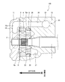
- FIG. 1 is a cross-sectional view of a vane pump according to an embodiment of the present invention.
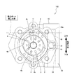
- FIG. 2 is a plan view of the vane pump according to the embodiment of the present invention, and shows a state in which the pump cover is removed.
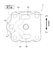
- FIG. 3 is a plan view showing a pump cover of the vane pump according to the embodiment of the present invention.
- the vane pump 100 is used as a fluid pressure supply source for a fluid pressure device mounted on a vehicle, for example, a continuously variable transmission.
- a fixed displacement vane pump 100 using hydraulic oil as a working fluid will be described.
- the vane pump 100 may be a variable displacement vane pump.
- the vane pump 100 is configured such that the power of an engine (not shown) is transmitted to the end of the drive shaft 1 and the rotor 2 connected to the drive shaft 1 rotates.
- the rotor 2 rotates counterclockwise as indicated by an arrow in FIG.
- the vane pump 100 includes a plurality of vanes 3 provided so as to be capable of reciprocating in the radial direction with respect to the rotor 2, the rotor 2 being housed, and the rotation of the rotor 2.
- a cam ring 4 having a cam surface 4a which is an inner peripheral surface on which the tip slides, a pump body 10 having an accommodating recess 10a for accommodating the cam ring 4, and a pump cover 11 fastened to the pump body 10 and sealing the accommodating recess 10a. And comprising.
- the drive shaft 1 is rotatably supported by the pump body 10.
- the rotor 2 is formed with slits 7 opening in the outer peripheral surface in a radial pattern at predetermined intervals.
- the vane 3 is inserted into the slit 7 so as to be reciprocally movable.
- a back pressure chamber 8 into which discharge pressure is guided is defined by the base end portion of the vane 3.
- Adjacent back pressure chambers 8 communicate with each other by a back pressure groove 8 a (see FIG. 1) formed in the pump cover 11. In FIG. 3, the back pressure groove 8a is not shown.
- the vane 3 is pressed in the direction of coming out of the slit 7 by the pressure of the hydraulic oil guided to the back pressure chamber 8, and the tip part comes into contact with the cam surface 4 a of the cam ring 4.
- a plurality of pump chambers 6 are defined inside the cam ring 4 by the outer peripheral surface of the rotor 2, the cam surface 4 a of the cam ring 4, and the adjacent vanes 3.
- the cam ring 4 is an annular member whose inner peripheral cam surface 4a has a substantially oval shape.
- the cam ring 4 includes a suction region 4 b that expands the volume of the pump chamber 6 defined between the vanes 3 that slide on the cam surface 4 a as the rotor 2 rotates, and a discharge region 4 c that contracts the volume of the pump chamber 6. And having.
- each pump chamber 6 expands and contracts as the rotor 2 rotates.
- the cam ring 4 has two suction areas 4b and two discharge areas 4c.
- the side plate 5 is disposed in contact with one side (the right side in FIG. 1) of the rotor 2 and the cam ring 4, and the pump cover 11 is placed on the other side (the left side in FIG. 1). Arranged in contact.
- the side plate 5 and the pump cover 11 are disposed with both side surfaces of the rotor 2 and the cam ring 4 being sandwiched, and seal the pump chamber 6.
- the side plate 5 is formed with two arc-shaped discharge ports 20 that open corresponding to the discharge region 4 c of the cam ring 4.
- a high-pressure chamber 21 into which hydraulic oil discharged from the pump chamber 6 in the discharge region 4c is guided is formed.
- the hydraulic oil discharged from the pump chamber 6 is guided to the high pressure chamber 21 through the discharge port 20 of the side plate 5.
- the hydraulic oil guided to the high pressure chamber 21 is supplied to an external hydraulic device through a discharge passage (not shown) formed in the pump body 10 and communicating with the high pressure chamber 21.
- each back pressure port 22 communicates with the back pressure chamber 8.
- the hydraulic oil in the high pressure chamber 21 is guided to the back pressure chamber 8 through the back pressure port 22.
- the pump body 10 and the pump cover 11 are formed with a suction passage 30 that communicates with a tank (not shown) and guides the hydraulic oil in the tank to the pump chamber 6.
- the pump cover 11 is opened corresponding to the two suction regions 4 b (see FIG. 2) of the cam ring 4, and has two arc-shaped suction ports 30 a that guide the hydraulic oil to the pump chamber 6. 30b is formed.
- a specific configuration of the suction passage 30 will be described in detail later.
- the vane pump 100 As the rotor 2 rotates, the vane pump 100 sucks hydraulic oil from the tank into the pump chambers 6 in the suction region 4b of the cam ring 4 through the suction ports 30a and 30b and the suction passage 30 and also in the discharge region 4c of the cam ring 4. The hydraulic oil is discharged from the pump chamber 6 to the outside through the discharge port 20 and the discharge passage. In this way, the vane pump 100 supplies and discharges hydraulic oil by the expansion and contraction of each pump chamber 6 accompanying the rotation of the rotor 2.
- the vane pump 100 is attached to a vehicle or the like so that the drive shaft 1 extends in parallel with the ground, in other words, the axial direction of the drive shaft 1 is a horizontal direction.
- the specific structure of the suction passage 30 in the state in which the vane pump 100 was attached to the vehicle etc. is demonstrated.
- the direction perpendicular to the paper surface corresponds to the vertical direction.
- the vertical direction corresponds to the vertical direction.
- the vane pump 100 includes a suction passage 30 that is formed over the pump body 10 and the pump cover 11 and guides the working oil of the tank to the pump chamber 6 in the suction region 4b.
- the suction passage 30 has a first passage 31 formed in the pump body 10 so as to extend in the vertical direction, and a pump body so as to branch from the first passage 31 and extend in the horizontal direction.
- the first passage 31 is formed in the pump body 10 so as to extend in a direction perpendicular to the drive shaft 1 (vertical direction).
- a hydraulic pipe (not shown) that communicates with the tank is connected to the first passage 31.
- the second passage 32 is provided linearly along the axial direction (horizontal direction) of the drive shaft 1 so as to extend from the first passage 31 toward the pump cover 11.
- the two suction ports 30 a and 30 b open in correspondence with the two suction regions 4 b (see FIG. 2) of the cam ring 4, and are formed in an arc shape that guides hydraulic oil to the pump chamber 6.
- the suction ports 30 a and 30 b are formed in the pump cover 11 and constitute a part of the suction passage 30.
- a side plate hereinafter referred to as a “second side plate” that abuts on the other side surface (the left side surface in FIG. 1) of the rotor 2 and the cam ring 4 is further provided, and the second side plate is provided.
- Suction ports 30a and 30b may be formed.
- the opening of the communication passage 33 on the end face of the pump cover 11 communicates with the pump chamber 6 through the suction ports 30a and 30b formed in the second side plate, so that the operation from the suction passage 30 is performed. Oil is sucked into the pump chamber 6.
- the communication path 33 includes a merging path 33c communicating with the second path 32, and two branch paths 33a branched from the merging path 33c and connected to the suction ports 30a and 30b, respectively. 33b.
- the hydraulic fluid guided from the tank through the hydraulic piping is guided to the suction ports 30a and 30b through the first passage 31, the second passage 32, and the communication passage 33, and is sucked into the pump chamber 6 in the suction region 4b.
- the vane pump 100 further includes an air pocket 40 that has a bottom 40a and opens to the suction passage 30 to store air.
- the air pocket 40 is formed so as to open to a branch portion (connecting portion) between the first passage 31 and the second passage 32 and extend upward in the vertical direction (upward in FIG. 2). More specifically, the air pocket 40 is a non-through hole formed vertically on the first passage 31 and the second passage 32 and coaxially with the first passage 31, and sandwiches the second passage 32 therebetween.
- the first passage 31 is provided on the opposite side. The air pocket 40 can be easily processed by being provided coaxially with the first passage 31.
- the air pocket 40 has a dead end by the bottom 40a, and is formed to open from the upper side in the vertical direction with respect to the suction passage 30. 2 and 3 indicates the uppermost position of the suction port.
- the bottom 40a of the air pocket 40 is provided so as to be at the uppermost position of the suction port, that is, at a position higher than the suction port 30a (upward in the vertical direction) of the two suction ports 30a and 30b. (See FIG. 2).
- the air pocket 40 has a value obtained by adding the volume of the suction passage 30 formed in the pump body 10 and the pump cover 11 and the volume of a strainer (not shown) provided in the hydraulic piping connecting the vane pump 100 and the tank. It is formed to have a volume equal to or greater than the value obtained by multiplying the air content of the hydraulic oil.
- the hydraulic oil that operates the vane pump 100 may contain air.
- air moves upward in the vertical direction along the flow path wall section that defines the suction passage 30. That is, the air in the hydraulic oil tends to accumulate at the uppermost portion where the vertical height position is highest in the flow path through which the hydraulic oil passes.
- the air pocket 40 is positioned above the suction port 30a which is the uppermost position in the suction passage 30 in the vertical direction. That is, the air pocket 40 is provided at a position higher than any part of the suction passage 30. Therefore, the air contained in the working oil in the suction passage 30 and the working oil in the strainer provided between the vane pump 100 and the tank or in the hydraulic piping passes through the wall portion and is located at the uppermost portion in the vertical direction. Led to.
- the air pocket 40 has a dead end having a bottom portion 40a, and the hydraulic oil sucked from the tank does not actively pass during operation of the vane pump 100.
- the air pocket 40 does not constitute the suction passage 30 for guiding the hydraulic oil, the air accumulated in the air pocket 40 is hardly sucked into the pump chamber 6 immediately after starting.
- the vane pump 100 used under a low temperature condition the viscosity of the hydraulic oil is high and the viscous resistance is increased, so that the sliding of the vane 3 is hindered and the startability is particularly lowered. Since the vane pump 100 can quickly increase the discharge pressure by storing air in the air pocket 40, startability can be ensured even when the vane pump 100 is used under a low temperature condition.
- the air pocket 40 is formed to have a volume equal to or larger than a value obtained by multiplying the volume of the suction passage 30 and the volume of the strainer by the air content rate of the hydraulic oil. It is possible to prevent air from remaining in the suction passage 30.
- the air pocket 40 is formed coaxially with the first passage 31 and opens into the first passage 31 from above in the vertical direction.
- the air pocket 40 can be formed in any position and shape as long as the air in the hydraulic oil can be stored.
- the air pocket 40 may be a straight non-through hole extending upward in the vertical direction so as to be inclined from the first passage 31. Moreover, as long as it is formed so as to extend upward in the vertical direction, the first passage 31 may be opened from a substantially horizontal direction. Further, the air pocket 40 may be opened to any one of the second passage 32, the communication passage 33, and the suction ports 30a and 30b.
- the number of air pockets 40 is not limited to one, and a plurality of air pockets 40 may be provided.
- the bottom 40a of the air pocket 40 is provided at a position higher than the suction port 30a located above the vertical direction, and is provided so as to be above the vertical direction above any part in the suction passage 30. Since air gathers at a high part, it is desirable to provide the air pocket 40 at the top, but the present invention is not limited to this and may be formed at an arbitrary position. Even if the air pocket 40 is not provided at the uppermost part, a part of the air in the suction passage 30 that is lower than the air pocket 40 is likely to be stored in the air pocket 40, and therefore the air pocket 40 is not provided. Compared with, startability can be improved.
- the vane pump 100 is attached to a vehicle so that the drive shaft 1 may become parallel to the ground, and the suction passage 30 has the 1st channel
- the vane pump 100 is not limited to this, and the attachment to a vehicle or the like and the configuration of the suction passage 30 may be other.
- the air pocket 40 opens to the suction passage 30 and is formed so as to extend vertically upward in a state where the vane pump 100 is attached, thereby storing air in the hydraulic oil. It is possible to prevent air from being sucked into the pump chamber 6 at the time of starting.
- the vane pump 100 since the air pocket 40 having the bottom portion 40a and extending vertically upward opens in the first passage 31 of the suction passage 30, the air contained in the hydraulic oil is stored in the air pocket 40, The occurrence of air accumulation in the suction passage 30 is suppressed. Therefore, the suction of air into the pump chamber 6 is suppressed, and the discharge pressure can be quickly increased at the start. Therefore, the startability of the vane pump 100 can be improved.
- the bottom 40a of the air pocket 40 is provided vertically above the suction port 30a at the higher position of the two suction ports 30a and 30b.
- the air pocket 40 is configured as the uppermost portion at a position higher than any portion of the suction passage 30, so that air can be stored more reliably. Therefore, the startability of the vane pump 100 can be improved more effectively.
- the vane pump 100 includes a rotor 2 connected to a drive shaft 1, a plurality of vanes 3 provided so as to freely reciprocate with respect to the rotor 2, and a cam surface 4 a on which the tip of the vane 3 slides as the rotor 2 rotates.
- a pump chamber 6 defined by the rotor 2, the cam ring 4, and a pair of adjacent vanes 3, a pump body 10 that houses the cam ring 4, and a pump cover 11 that seals the pump body 10.
- a suction passage 30 formed over the pump body 10 and the pump cover 11 to guide hydraulic oil to the pump chamber 6, and an air pocket 40 having a bottom portion 40a and being open to the suction passage 30 and extending upward in the vertical direction; .
- the vane pump 100 further includes a suction port (30a, 30b) that opens into the pump chamber 6 and guides hydraulic oil to the pump chamber 6.
- the bottom 40a of the air pocket 40 is the uppermost portion of the suction port (30a, 30b). It is provided in a higher position.
- the vane pump 100 includes two suction ports 30a and 30b, and the bottom portion 40a of the air pocket 40 is provided at a position higher than the suction port 30a positioned vertically above the two suction ports 30a and 30b.
- the air pocket 40 is provided at a position where air easily collects. Accordingly, it is possible to more reliably prevent air from being sucked into the pump chamber 6 and further improve the startability.
- the suction passage 30 includes a first passage 31 formed in the pump body 10 and extending in the vertical direction, and a second passage 32 formed in the pump body 10 and branched from the first passage 31 and extending in the horizontal direction.
- a communication passage 33 that is formed in the pump cover 11 and communicates the second passage 32 and the suction ports 30a and 30b.
- the air pocket 40 is connected to the first passage 31 vertically above the first passage 31. It is provided on the same axis.
Landscapes
- Engineering & Computer Science (AREA)
- Mechanical Engineering (AREA)
- General Engineering & Computer Science (AREA)
- Rotary Pumps (AREA)
- Details And Applications Of Rotary Liquid Pumps (AREA)
Abstract
ベーンポンプ(100)は、ロータ(2)と、ロータ(2)に対して往復動自在に設けられる複数のベーン(3)と、ロータ(2)の回転に伴ってベーン(3)の先端が摺動する内周面(4a)を有するカムリング(4)と、ロータ(2)とカムリング(4)と一対の隣り合うベーン(3)とによって区画されるポンプ室(6)と、カムリング(4)を収容するポンプボディ(10)と、ポンプボディ(10)を封止するポンプカバー11と、ポンプボディ(10)とポンプカバー(11)とにわたって形成されポンプ室(6)に作動油を導く吸込通路(30)と、底部(40a)を有すると共に吸込通路(30)に開口し鉛直方向の上方に延びるように形成されるエアポケット(40)と、を備える。
Description
本発明は、ベーンポンプに関するものである。
JP1999-230057Aには、ハウジング内に収納されて回転駆動されるロータと、ロータのスリット内で摺動運動をするベーンと、ベーンの外側にあってロータ、ベーン等とポンプ室を形成するカムリングと、を備えるベーンポンプが開示されている。
このようなベーンポンプでは、停止状態が続くと、作動油に含有されるエアが、ポンプ室に吸い込まれる作動油を導く吸込通路内に溜まることがある。このようなエア溜りが生じると、始動時においてポンプ室にエアが吸い込まれ、吐出圧の立ち上がりが遅れるおそれがある。
本発明は、ベーンポンプの始動性を向上させることを目的とする。
本発明のある態様によれば、駆動軸に連結されたロータと、ロータに対して径方向に往復動自在に設けられる複数のベーンと、ロータの回転に伴ってベーンの先端が摺動する内周面を有するカムリングと、ロータとカムリングと一対の隣り合うベーンとによって区画されるポンプ室と、カムリングを収容するポンプボディと、ポンプボディを封止するポンプカバーと、ポンプボディとポンプカバーとにわたって形成されポンプ室に作動流体を導く吸込通路と、底部を有すると共に吸込通路に開口し鉛直方向の上方に延びるように形成されるエアポケットと、を備える。
以下、添付図面を参照しながら本発明の実施形態について説明する。
まず、図1から図3を参照して、本発明の実施形態に係るベーンポンプ100の全体構成について説明する。
ベーンポンプ100は、車両に搭載される流体圧機器、例えば、無段変速機等の流体圧供給源として用いられる。本実施形態では、作動油を作動流体とする固定容量型のベーンポンプ100について説明する。なお、ベーンポンプ100は、可変容量型のベーンポンプであってもよい。
ベーンポンプ100は、駆動軸1の端部にエンジン(図示省略)の動力が伝達され、駆動軸1に連結されたロータ2が回転するものである。ロータ2は、図2において矢印で示すように反時計回りに回転する。
図1及び図2に示すように、ベーンポンプ100は、ロータ2に対して径方向に往復動自在に設けられる複数のベーン3と、ロータ2を収容すると共にロータ2の回転に伴ってベーン3の先端が摺動する内周面であるカム面4aを有するカムリング4と、カムリング4を収容する収容凹部10aを有するポンプボディ10と、ポンプボディ10に締結され収容凹部10aを封止するポンプカバー11と、を備える。駆動軸1は、図2に示すように、ポンプボディ10に回転自在に支持される。
図2に示すように、ロータ2には、外周面に開口するスリット7が所定間隔をおいて放射状に形成される。スリット7には、ベーン3が往復動自在に挿入される。スリット7内には、吐出圧が導かれる背圧室8がベーン3の基端部によって区画される。また、隣り合う背圧室8は、ポンプカバー11に形成される背圧溝8a(図1参照)によって互いに連通される。なお、図3では、背圧溝8aの図示を省略している。
ベーン3は、背圧室8に導かれる作動油の圧力によって、スリット7から抜け出る方向に押圧され、先端部がカムリング4のカム面4aに当接する。これにより、カムリング4の内部には、ロータ2の外周面、カムリング4のカム面4a、及び隣り合うベーン3によって複数のポンプ室6が区画される。
カムリング4は、内周のカム面4aが略長円形状をした環状の部材である。カムリング4は、ロータ2の回転に伴ってカム面4aを摺動する各ベーン3間に区画されるポンプ室6の容積を拡張する吸込領域4bと、ポンプ室6の容積を収縮する吐出領域4cと、を有する。このように、各ポンプ室6は、ロータ2の回転に伴って拡縮する。本実施形態では、カムリング4は、2つの吸込領域4b及び2つの吐出領域4cを有する。
図1に示すように、ロータ2及びカムリング4の一側面(図1では右側面)にはサイドプレート5が当接して配置され、他側面(図1では左側面)にはポンプカバー11が当接して配置される。サイドプレート5とポンプカバー11とは、ロータ2及びカムリング4の両側面を挟んだ状態で配置され、ポンプ室6を密閉する。
サイドプレート5には、カムリング4の吐出領域4cに対応して開口する円弧状の2つの吐出ポート20が貫通して形成される。
ポンプボディ10には、吐出領域4cにあるポンプ室6から吐出される作動油が導かれる高圧室21が形成される。ポンプ室6から吐出される作動油は、サイドプレート5の吐出ポート20を通じて高圧室21に導かれる。高圧室21に導かれた作動油は、ポンプボディ10に形成され高圧室21に連通する吐出通路(図示省略)を通じて外部の油圧機器へと供給される。
また、サイドプレート5には、高圧室21に連通する円弧状の2つの背圧ポート22が形成される。各背圧ポート22は、背圧室8に連通する。これにより、高圧室21の作動油が背圧ポート22を通じて背圧室8に導かれる。
ポンプボディ10とポンプカバー11には、タンク(図示省略)と連通し、タンクの作動油をポンプ室6へと導く吸込通路30が両者にわたって形成される。ポンプカバー11には、図3に示すように、カムリング4の2つの吸込領域4b(図2参照)に対応して開口し、ポンプ室6に作動油を導く円弧状の2つの吸込ポート30a,30bが形成される。吸込通路30の具体的構成については、後に詳しく説明する。
ベーンポンプ100は、ロータ2の回転に伴って、カムリング4の吸込領域4bにおける各ポンプ室6に吸込ポート30a,30b及び吸込通路30を通じてタンクから作動油を吸込むと共に、カムリング4の吐出領域4cにおける各ポンプ室6から吐出ポート20及び吐出通路を通じて作動油を外部へ吐出する。このように、ベーンポンプ100は、ロータ2の回転に伴う各ポンプ室6の拡縮によって作動油を給排する。
次に、図1から3を参照して、吸込通路30及び吸込ポート30a,30bの具体的構成について、詳しく説明する。
本実施形態では、駆動軸1が地面と平行に延びるように、言い換えれば駆動軸1の軸方向が水平方向となるようにベーンポンプ100が車両等に取り付けられる。以下では、ベーンポンプ100が車両等に取り付けられた状態における吸込通路30の具体的構成について説明する。なお、図1では、紙面に対して垂直方向が鉛直方向に相当する。図2及び図3では、上下方向が鉛直方向に相当する。
図1に示すように、ベーンポンプ100は、ポンプボディ10及びポンプカバー11にわたって形成され、タンクの作動油を吸込領域4bにあるポンプ室6へと導く吸込通路30を備える。
吸込通路30は、図1から図3に示すように、鉛直方向に延びるようにポンプボディ10に形成される第1通路31と、第1通路31から分岐して水平方向に延びるようにポンプボディに形成される第2通路32と、ポンプカバー11に形成され第2通路32と2つの吸込ポート30a,30bとを連通して2つの吸込ポート30a,30bへと作動油を導く連通路33と、を備える。
第1通路31は、図2に示すように、駆動軸1に対して垂直方向(鉛直方向)に延在するようにポンプボディ10に形成される。第1通路31には、タンクと連通する油圧配管(図示省略)が接続される。
第2通路32は、図1に示すように、第1通路31からポンプカバー11に向かって延びるように駆動軸1の軸方向(水平方向)に沿って直線状に設けられる。
2つの吸込ポート30a,30bは、図3に示すように、それぞれカムリング4の2つの吸込領域4b(図2参照)に対応して開口し、ポンプ室6に作動油を導く円弧状に形成される。吸込ポート30a,30bは、ポンプカバー11に形成されて吸込通路30の一部を構成する。なお、図示を省略するが、ロータ2及びカムリング4の他側面(図1の左側面)に当接するサイドプレート(以下、「第2サイドプレート」と称する。)をさらに設け、第2サイドプレートに吸込ポート30a,30bが形成されてもよい。このような場合には、ポンプカバー11の端面における連通路33の開口部が、第2サイドプレートに形成された吸込ポート30a,30bを通じてポンプ室6に連通することにより、吸込通路30からの作動油がポンプ室6に吸い込まれる。
連通路33は、図1及び図3に示すように、第2通路32に連通する合流通路33cと、合流通路33cから分岐してそれぞれ吸込ポート30a,30bに接続される2つの分岐通路33a,33bと、を有する。
油圧配管を通じてタンクから導かれる作動油は、第1通路31、第2通路32、及び連通路33を通じて吸込ポート30a,30bに導かれ、吸込領域4bにあるポンプ室6に吸い込まれる。
ベーンポンプ100は、図2に示すように、底部40aを有すると共に吸込通路30に開口してエアを貯留するエアポケット40をさらに備える。
エアポケット40は、図2に示すように、第1通路31と第2通路32との分岐部分(接続部分)に開口し、鉛直方向上方(図2中上方)に延びるように形成される。より具体的には、エアポケット40は、第1通路31及び第2通路32の鉛直方向上方であって第1通路31と同軸上に形成される非貫通孔であり、第2通路32を挟んで第1通路31とは反対側に設けられる。エアポケット40は、第1通路31と同軸上に設けられることにより、容易に加工することができる。
エアポケット40は、底部40aによって行き止まりとなっており、吸込通路30に対して鉛直方向上方から開口するように形成される。図2及び図3における二点鎖線は、吸込ポートの最上位置を示すものである。エアポケット40の底部40aは、吸込ポートの最上位置、即ち2つの吸込ポート30a,30bのうち鉛直方向の上方に位置する吸込ポート30aよりも高い位置(鉛直方向上方)となるように設けられる(図2参照)。
エアポケット40は、ポンプボディ10及びポンプカバー11に形成される吸込通路30の容積と、ベーンポンプ100とタンクとを接続する油圧配管に設けられるストレーナ(図示省略)の容積と、を加算した値に作動油のエア含有率を乗算した値以上の容積となるように形成される。
ここで、ベーンポンプ100を作動する作動油には、エアが含有されていることがある。このようなエアは、ベーンポンプ100の停止状態が継続すると、吸込通路30を区画する流路壁部を伝って鉛直方向上方へ移動する。つまり、作動油内のエアは、作動油が通過する流路内において、鉛直方向の高さ位置が最も高い最上部に溜まり易い。
ベーンポンプ100では、エアポケット40が、吸込通路30において最上位置となる吸込ポート30aよりも鉛直方向の上方に位置する。つまり、エアポケット40は、吸込通路30のいずれの部位よりも高い位置に設けられる。よって、吸込通路30内の作動油及びベーンポンプ100とタンクとの間に設けられるストレーナや油圧配管内の作動油に含有されたエアは、壁部を伝い鉛直方向の最上部に位置するエアポケット40に導かれる。
また、エアポケット40は、底部40aを有する行き止まりとなっており、ベーンポンプ100の作動中においては、タンクから吸い込まれる作動油が積極的に通過するものではない。言い換えれば、エアポケット40は、作動油を導く吸込通路30を構成するものではないため、エアポケット40内に溜まるエアが始動直後にポンプ室6に吸い込まれることはほとんどない。
よって、停止状態が長時間継続した場合であっても、吸込通路30内におけるエア溜りの発生が抑制され、ポンプ室6へのエアの吸い込みを抑制することができる。したがって、ポンプ室6からの吐出圧を速やかに上昇させることができ、ベーンポンプ100の始動性を向上させることができる。
また、低温状況下で使用されるベーンポンプ100では、作動油の粘度が高く粘性抵抗が大きくなるため、ベーン3の摺動が妨げられ始動性が特に低下する。ベーンポンプ100は、エアポケット40にエアを貯留することで吐出圧を速やかに上昇することができるため、低温状況下で使用される場合であっても、始動性を確保することができる。
また、エアポケット40は、吸込通路30の容積とストレーナの容積とを加算した値に作動油のエア含有率を乗算した値以上の容積となるように形成されるため、エアポケット40内にエアを貯留しきれず、吸込通路30内にエアが残留することを防止できる。
次に、本実施形態の変形例について説明する。
上記実施形態では、エアポケット40は、第1通路31と同軸上に形成され、鉛直方向の上方から第1通路31に開口する。これに対し、エアポケット40は、作動油内のエアを貯留可能であれば、任意の位置及び形状に形成することができる。
例えば、エアポケット40は、第1通路31から傾斜するように鉛直方向の上方へ延びる直線状の非貫通孔でもよい。また、鉛直方向上方へ延びるように形成されるものであれば、略水平方向から第1通路31に開口するものでもよい。また、エアポケット40は、第2通路32、連通路33、及び吸込ポート30a,30bにいずれかに開口するものでもよい。エアポケット40の数は、一つに限らず、複数設けてもよい。
また、上記実施形態では、エアポケット40の底部40aは、鉛直方向上方にある吸込ポート30aよりも高い位置に設けられ、吸込通路30におけるどの部位よりも鉛直方向の上方となるように設けられる。エアは、高さが高い部位に集まるため、最上部にエアポケット40を設けることが望ましいが、これに限らず、任意の位置に形成してもよい。エアポケット40を最上部に設けなくても、吸込通路30のうちエアポケット40よりも低い位置にある一部のエアはエアポケット40内に貯留されやすくなるため、エアポケット40が設けられない場合と比較して、始動性を向上させることができる。
また、上記実施形態では、ベーンポンプ100は、駆動軸1が地面と平行となるように車両に取り付けられ、吸込通路30は、鉛直方向に延びる第1通路31及び水平方向に延びる第2通路32を有する。ベーンポンプ100は、これに限らず、車両等への取付や、吸込通路30の構成は、その他のものであってもよい。いずれの場合であっても、エアポケット40は、吸込通路30に開口し、ベーンポンプ100が取り付けられた状態において鉛直方向上方に延びるように形成されることにより、作動油内のエアを貯留して、始動時でのポンプ室6へのエアの吸込みを防止することができる。
以上の実施形態によれば、以下に示す効果を奏する。
ベーンポンプ100は、底部40aを有して鉛直方向上方へ延びるエアポケット40が吸込通路30の第1通路31に開口するため、作動油に含有されるエアは、エアポケット40内に貯留されて、吸込通路30内でのエア溜りの発生が抑制される。よって、ポンプ室6へのエアの吸い込みが抑制され、始動時において吐出圧を速やかに上昇させることができる。したがって、ベーンポンプ100の始動性を向上させることができる。
また、エアポケット40の底部40aは、2つの吸込ポート30a,30bのうち高い位置にある吸込ポート30aよりも鉛直方向上方に設けられる。このように、エアポケット40が、吸込通路30のどの部位よりも高い位置にある最上部として構成されることにより、より確実にエアを貯留することができる。よって、ベーンポンプ100の始動性をより効果的に向上させることができる。
以下、本発明の実施形態の構成、作用、及び効果をまとめて説明する。
ベーンポンプ100は、駆動軸1に連結されたロータ2と、ロータ2に対して往復動自在に設けられる複数のベーン3と、ロータ2の回転に伴ってベーン3の先端が摺動するカム面4aを有するカムリング4と、ロータ2とカムリング4と一対の隣り合うベーン3とによって区画されるポンプ室6と、カムリング4を収容するポンプボディ10と、ポンプボディ10を封止するポンプカバー11と、ポンプボディ10とポンプカバー11とにわたって形成されポンプ室6に作動油を導く吸込通路30と、底部40aを有すると共に吸込通路30に開口し鉛直方向の上方に延びるように形成されるエアポケット40と、を備える。
この構成では、底部40aを有して鉛直方向上方へ延びるエアポケット40が吸込通路30に連通するため、作動油に含有されるエアは、エアポケット40内に貯留される。このため、吸込通路30内でのエア溜りの発生が抑制される。よって、始動時において、ポンプ室6へのエアの吸い込みを抑制することができ、吐出圧を速やかに上昇させることができる。したがって、ベーンポンプ100の始動性が向上する。
また、ベーンポンプ100は、ポンプ室6に開口して作動油をポンプ室6に導く吸込ポート(30a,30b)をさらに備え、エアポケット40の底部40aは、吸込ポート(30a,30b)の最上部よりも高い位置に設けられる。
また、ベーンポンプ100は、2つの吸込ポート30a,30bを備え、エアポケット40の底部40aは、2つの吸込ポート30a,30bのうち鉛直方向上方に位置する吸込ポート30aよりも高い位置に設けられる。
これらの構成では、エアが溜まりやすい位置にエアポケット40が設けられる。したがって、ポンプ室6へのエアの吸い込みをより確実に防止して、始動性をさらに向上させることができる。
また、ベーンポンプ100では、吸込通路30は、ポンプボディ10に形成され鉛直方向に延びる第1通路31と、ポンプボディ10に形成され第1通路31から分岐して水平方向に延びる第2通路32と、ポンプカバー11に形成され、第2通路32と吸込ポート30a,30bとを連通する連通路33と、を有し、エアポケット40は、第1通路31の鉛直方向上方に第1通路31と同軸上に設けられる。
以上、本発明の実施形態について説明したが、上記実施形態は本発明の適用例の一部を示したに過ぎず、本発明の技術的範囲を上記実施形態の具体的構成に限定する趣旨ではない。
本願は2016年6月13日に日本国特許庁に出願された特願2016-117251に基づく優先権を主張し、この出願の全ての内容は参照により本明細書に組み込まれる。
Claims (4)
- ベーンポンプであって、
駆動軸に連結されたロータと、
前記ロータに対して径方向に往復動自在に設けられる複数のベーンと、
前記ロータの回転に伴って前記ベーンの先端が摺動する内周面を有するカムリングと、
前記ロータと前記カムリングと一対の隣り合う前記ベーンとによって区画されるポンプ室と、
前記カムリングを収容するポンプボディと、
前記ポンプボディを封止するポンプカバーと、
前記ポンプボディと前記ポンプカバーとにわたって形成され前記ポンプ室に作動流体を導く吸込通路と、
底部を有すると共に前記吸込通路に開口し鉛直方向の上方に延びるように形成されるエアポケットと、を備えるベーンポンプ。 - 請求項1に記載のベーンポンプであって、
前記ポンプ室に開口して作動流体を前記ポンプ室に導く吸込ポートをさらに備え、
前記エアポケットの前記底部は、前記吸込ポートの最上部よりも高い位置に設けられるベーンポンプ。 - 請求項2に記載のベーンポンプであって、
2つの前記吸込ポートを備え、
前記エアポケットの前記底部は、2つの前記吸込ポートのうち鉛直方向上方に位置する前記吸込ポートよりも高い位置に設けられるベーンポンプ。 - 請求項2に記載のベーンポンプであって、
前記吸込通路は、
前記ポンプボディに形成され鉛直方向に延びる第1通路と、
前記ポンプボディに形成され前記第1通路から分岐して水平方向に延びる第2通路と、
前記ポンプカバーに形成され、前記第2通路と前記吸込ポートとを連通する連通路と、を有し、
前記エアポケットは、前記第1通路の鉛直方向上方に前記第1通路と同軸上に設けられるベーンポンプ。
Applications Claiming Priority (2)
| Application Number | Priority Date | Filing Date | Title |
|---|---|---|---|
| JP2016117251A JP6700994B2 (ja) | 2016-06-13 | 2016-06-13 | ベーンポンプ |
| JP2016-117251 | 2016-06-13 |
Publications (1)
| Publication Number | Publication Date |
|---|---|
| WO2017217224A1 true WO2017217224A1 (ja) | 2017-12-21 |
Family
ID=60663140
Family Applications (1)
| Application Number | Title | Priority Date | Filing Date |
|---|---|---|---|
| PCT/JP2017/019940 Ceased WO2017217224A1 (ja) | 2016-06-13 | 2017-05-29 | ベーンポンプ |
Country Status (2)
| Country | Link |
|---|---|
| JP (1) | JP6700994B2 (ja) |
| WO (1) | WO2017217224A1 (ja) |
Cited By (1)
| Publication number | Priority date | Publication date | Assignee | Title |
|---|---|---|---|---|
| CN109882410A (zh) * | 2019-04-12 | 2019-06-14 | 重庆工商大学 | 一种旋片电子抽气泵 |
Citations (3)
| Publication number | Priority date | Publication date | Assignee | Title |
|---|---|---|---|---|
| JPH0431681A (ja) * | 1990-05-24 | 1992-02-03 | Toyoda Mach Works Ltd | ベーンポンプ |
| JP2001032782A (ja) * | 1999-07-22 | 2001-02-06 | Honda Motor Co Ltd | ベーンポンプ |
| JP2013060847A (ja) * | 2011-09-13 | 2013-04-04 | Kyb Co Ltd | ベーンポンプ |
-
2016
- 2016-06-13 JP JP2016117251A patent/JP6700994B2/ja active Active
-
2017
- 2017-05-29 WO PCT/JP2017/019940 patent/WO2017217224A1/ja not_active Ceased
Patent Citations (3)
| Publication number | Priority date | Publication date | Assignee | Title |
|---|---|---|---|---|
| JPH0431681A (ja) * | 1990-05-24 | 1992-02-03 | Toyoda Mach Works Ltd | ベーンポンプ |
| JP2001032782A (ja) * | 1999-07-22 | 2001-02-06 | Honda Motor Co Ltd | ベーンポンプ |
| JP2013060847A (ja) * | 2011-09-13 | 2013-04-04 | Kyb Co Ltd | ベーンポンプ |
Cited By (2)
| Publication number | Priority date | Publication date | Assignee | Title |
|---|---|---|---|---|
| CN109882410A (zh) * | 2019-04-12 | 2019-06-14 | 重庆工商大学 | 一种旋片电子抽气泵 |
| CN109882410B (zh) * | 2019-04-12 | 2024-01-30 | 重庆工商大学 | 一种旋片电子抽气泵 |
Also Published As
| Publication number | Publication date |
|---|---|
| JP2017223125A (ja) | 2017-12-21 |
| JP6700994B2 (ja) | 2020-05-27 |
Similar Documents
| Publication | Publication Date | Title |
|---|---|---|
| JP5877976B2 (ja) | ベーンポンプ | |
| US9239050B2 (en) | Vane pump | |
| JP2013079592A (ja) | ベーンポンプ | |
| IT201800020389A1 (it) | Dispositivo di pompaggio. | |
| CN102224344A (zh) | 滑片泵 | |
| JP6375212B2 (ja) | 可変容量型ベーンポンプ | |
| JP6111093B2 (ja) | ベーンポンプ | |
| WO2017217224A1 (ja) | ベーンポンプ | |
| JP6633901B2 (ja) | オイルポンプシステム | |
| WO2017068901A1 (ja) | ベーンポンプ | |
| JP5372582B2 (ja) | ベーンポンプ | |
| CN108026921A (zh) | 叶片泵 | |
| WO2017217223A1 (ja) | ベーンポンプ | |
| US20180223841A1 (en) | Vane pump | |
| JP2011085100A (ja) | ベーンポンプ | |
| JP2018035773A (ja) | ベーンポンプ | |
| JP2017145699A (ja) | ベーンポンプ | |
| WO2017051729A1 (ja) | 可変オイルポンプ | |
| CN113994094B (zh) | 可变排量润滑剂泵 | |
| JP2011132868A (ja) | ベーンポンプ | |
| JP6454247B2 (ja) | ベーンポンプ | |
| JP2017057793A (ja) | ベーンポンプ | |
| WO2024195481A1 (ja) | ベーンポンプ | |
| JP2010196682A (ja) | ベーンポンプ | |
| JP2019138281A (ja) | ベーンポンプ |
Legal Events
| Date | Code | Title | Description |
|---|---|---|---|
| 121 | Ep: the epo has been informed by wipo that ep was designated in this application |
Ref document number: 17813126 Country of ref document: EP Kind code of ref document: A1 |
|
| NENP | Non-entry into the national phase |
Ref country code: DE |
|
| 122 | Ep: pct application non-entry in european phase |
Ref document number: 17813126 Country of ref document: EP Kind code of ref document: A1 |